WO2016011618A1 - 一种风机电机测量风量的方法 - Google Patents
一种风机电机测量风量的方法 Download PDFInfo
- Publication number
- WO2016011618A1 WO2016011618A1 PCT/CN2014/082814 CN2014082814W WO2016011618A1 WO 2016011618 A1 WO2016011618 A1 WO 2016011618A1 CN 2014082814 W CN2014082814 W CN 2014082814W WO 2016011618 A1 WO2016011618 A1 WO 2016011618A1
- Authority
- WO
- WIPO (PCT)
- Prior art keywords
- air volume
- motor
- speed
- fan motor
- cfmi
- Prior art date
- Legal status (The legal status is an assumption and is not a legal conclusion. Google has not performed a legal analysis and makes no representation as to the accuracy of the status listed.)
- Ceased
Links
Classifications
-
- F—MECHANICAL ENGINEERING; LIGHTING; HEATING; WEAPONS; BLASTING
- F04—POSITIVE - DISPLACEMENT MACHINES FOR LIQUIDS; PUMPS FOR LIQUIDS OR ELASTIC FLUIDS
- F04D—NON-POSITIVE-DISPLACEMENT PUMPS
- F04D27/00—Control, e.g. regulation, of pumps, pumping installations or pumping systems specially adapted for elastic fluids
- F04D27/001—Testing thereof; Determination or simulation of flow characteristics; Stall or surge detection, e.g. condition monitoring
-
- F—MECHANICAL ENGINEERING; LIGHTING; HEATING; WEAPONS; BLASTING
- F04—POSITIVE - DISPLACEMENT MACHINES FOR LIQUIDS; PUMPS FOR LIQUIDS OR ELASTIC FLUIDS
- F04D—NON-POSITIVE-DISPLACEMENT PUMPS
- F04D25/00—Pumping installations or systems
- F04D25/02—Units comprising pumps and their driving means
- F04D25/06—Units comprising pumps and their driving means the pump being electrically driven
-
- G—PHYSICS
- G01—MEASURING; TESTING
- G01P—MEASURING LINEAR OR ANGULAR SPEED, ACCELERATION, DECELERATION, OR SHOCK; INDICATING PRESENCE, ABSENCE, OR DIRECTION, OF MOVEMENT
- G01P5/00—Measuring speed of fluids, e.g. of air stream; Measuring speed of bodies relative to fluids, e.g. of ship, of aircraft
-
- F—MECHANICAL ENGINEERING; LIGHTING; HEATING; WEAPONS; BLASTING
- F05—INDEXING SCHEMES RELATING TO ENGINES OR PUMPS IN VARIOUS SUBCLASSES OF CLASSES F01-F04
- F05D—INDEXING SCHEME FOR ASPECTS RELATING TO NON-POSITIVE-DISPLACEMENT MACHINES OR ENGINES, GAS-TURBINES OR JET-PROPULSION PLANTS
- F05D2270/00—Control
- F05D2270/30—Control parameters, e.g. input parameters
- F05D2270/304—Spool rotational speed
-
- F—MECHANICAL ENGINEERING; LIGHTING; HEATING; WEAPONS; BLASTING
- F05—INDEXING SCHEMES RELATING TO ENGINES OR PUMPS IN VARIOUS SUBCLASSES OF CLASSES F01-F04
- F05D—INDEXING SCHEME FOR ASPECTS RELATING TO NON-POSITIVE-DISPLACEMENT MACHINES OR ENGINES, GAS-TURBINES OR JET-PROPULSION PLANTS
- F05D2270/00—Control
- F05D2270/30—Control parameters, e.g. input parameters
- F05D2270/335—Output power or torque
-
- Y—GENERAL TAGGING OF NEW TECHNOLOGICAL DEVELOPMENTS; GENERAL TAGGING OF CROSS-SECTIONAL TECHNOLOGIES SPANNING OVER SEVERAL SECTIONS OF THE IPC; TECHNICAL SUBJECTS COVERED BY FORMER USPC CROSS-REFERENCE ART COLLECTIONS [XRACs] AND DIGESTS
- Y02—TECHNOLOGIES OR APPLICATIONS FOR MITIGATION OR ADAPTATION AGAINST CLIMATE CHANGE
- Y02B—CLIMATE CHANGE MITIGATION TECHNOLOGIES RELATED TO BUILDINGS, e.g. HOUSING, HOUSE APPLIANCES OR RELATED END-USER APPLICATIONS
- Y02B30/00—Energy efficient heating, ventilation or air conditioning [HVAC]
- Y02B30/70—Efficient control or regulation technologies, e.g. for control of refrigerant flow, motor or heating
Definitions
- the invention relates to a method for measuring the air volume of a fan motor.
- the motor in the traditional household air conditioner generally adopts single-phase AC motor PSC, single-phase AC motor, low efficiency, relatively energy consumption, high noise, and controllable intelligence. The degree is low.
- DC motors have gradually replaced AC motors.
- DC motors have motor controllers, which use motor controllers to achieve the purpose of electronic commutation of currents.
- ECM electrostatic clutched motor
- BLDC MOTOR Brushless DC motor
- the DC motor control board is connected to the air conditioner main board.
- the interface of the air-conditioning main board inputs the target speed to the DC motor control board through the output VSP voltage port, and the motor feeds back the actual speed of the motor through the FG port to realize the closed-loop control of the speed of the DC motor.
- the air inlet and outlet air filter or air duct is blocked, the air outlet of the air conditioner will decrease, which will affect the air conditioning cooling or heating effect. This is not desirable for air conditioning systems. For this reason, it is necessary to implement a constant air volume or air volume monitoring/alarm function on a conventional BLDC motor.
- the object of the present invention is to provide a method for measuring the air volume of a fan motor, which can accurately determine the air filter network. It blocks and outputs a signal alarm, and the mathematical model is simple, the control is reliable, and the precision is high.
- a method for measuring air volume by a fan motor characterized in that: it comprises the following steps:
- CFM0 CFMi+ (CFMi- 1-CFMi) X (ni-no) ⁇ (ni- ni- 1).
- the several air volume points CFMi described above include the maximum output air volume and the minimum output air volume.
- the fan motor described above adopts a BLDC motor or an ECM motor, including a motor unit and a motor controller, and the motor unit includes a rotating shaft, a permanent magnet rotor assembly, a stator assembly and a casing assembly, a permanent magnet rotor assembly and a stator assembly.
- the stator assembly includes a stator core and a coil winding wound on the stator core
- the motor controller includes a tantalum processor, an inverter circuit, and an operating parameter detecting circuit.
- the output end of the inverter circuit is connected to the coil winding, the operating parameter detecting circuit inputs the detected signal to the ⁇ processor, the output end of the ⁇ processor controls the inverter circuit, and the ⁇ processor inputs the set target air volume, and detects the air volume in real time.
- CFM0 is lower than the set target air volume, and the output signal is alarmed.
- the fan motor described above operates in a constant air volume control mode, and the ⁇ processor first measures whether the actual power reaches the rated power. If the measured actual power reaches the rated power, and the deviation between the detected air volume and the set air volume reaches a certain value, Alarm; When it is detected that the air volume deviates from the set air volume within the allowable range, choose not to alarm.
- the fan motor described above operates in the constant torque control mode. When the deviation between the detected air volume and the set air volume reaches a certain value, it is determined that the air filter is clogged and alarmed.
- the fan motor described above operates in the constant speed control mode. When the deviation between the detected air volume and the set air volume reaches a certain value, it is determined that the air filter is clogged and alarmed.
- the invention has the following effects:
- the mathematical model is simple, the control is reliable, and the accuracy is high.
- the fan motor works in the constant air volume control mode.
- the ⁇ processor first measures whether the actual power reaches the rated power. If the measured actual power reaches the rated power, then the deviation between the detected air volume Q1 and the set air volume Q0 is determined.
- the scheme is simple, ⁇ processing The amount of calculation is small and the feasibility is high.
- FIG. 1 is a schematic structural view of a conventional air conditioning fan system
- Figure 2 is a schematic view showing the installation of the fan motor of the present invention
- Figure 3 is a perspective view of the fan motor of the present invention.
- Figure 4 is a perspective view of the motor controller of the fan motor of the present invention.
- Figure 5 is a cross-sectional view of the fan motor of the present invention.
- Figure 6 is a block diagram showing an implementation circuit of a motor controller of the fan motor of the present invention.
- Figure 7 is a circuit diagram corresponding to Figure 6;
- Figure 10 is a graph showing the experimental data fitting of the direct power control constant air volume of the fan motor of the present invention.
- Figure 11 is a graph showing the fitting curve of the experimental data of the arbitrary input air volume by using the interpolation method of the fan motor of the present invention.
- Figure 12 is a control logic diagram of a constant air volume control method of the fan motor of the present invention.
- FIG. 13 is a schematic diagram of a control process of the constant air volume control method of the fan motor of the present invention
- Figure 14 is a schematic diagram of another control process of the constant air volume control method of the fan motor of the present invention
- Figure 15 is a constant air volume control of the fan motor of the present invention
- Fig. 16 is a schematic diagram of the wind volume measurement of the fan motor of the present invention.
- the present invention is shown in Fig. 1.
- a typical air conditioning ventilation duct referred to as a duct
- an air blowing system such as a gas stove or an air handler
- the figure is replaced by "motor + wind wheel”.
- the motor starts, the air blows. Since the number of air outlets and air inlets is related to the number of rooms, there is no uniform standard for the design of the pipeline, and the air filter may have different pressure drops. As a result, the actual air volume will vary depending on the blast system of the conventional single-phase AC motor-PSC motor in different pipes.
- the fan motor used in the invention is a BLDC motor or an ECM motor.
- the control of the product is an air conditioning system controller that controls all product operating devices and sends peripheral circuit and protocol setting information through a customized interface to the motor controller.
- the motor controller includes a ⁇ processor MCU or DSP electronic board for motor control. It has a power supply section that supplies power to each part of the controller circuit. The power supply is to set a DC bus voltage and current. Therefore, the control of the motor will perform power transfer.
- Low-cost and mass-produced motor controllers typically use shunt resistors as current and voltage sensing hardware, as system feedback to control motor drive to perform motor control, such as vector control, direct torque control, and other types of sensors or none. Sensor control. It is well known that any change in the operating period of an electronic component is the cause of the accuracy and durability of the test.
- Air filter The air filter should be replaced and repaired regularly. But this may be lost tracking for a long time. This will increase the frictional influence on the airflow pressure.
- Tube Road Control The piping system may change the cause of pressure changes due to dust and pipe rupture, zone control and on/off wind port system. According to the above situation, if the constant air volume control will produce a lot of instability factors.
- the fan motor is generally composed of a motor controller 2 and a motor unit 1, and the motor unit 1 includes a stator assembly 12, a rotor assembly 13 and a casing assembly 11, and the stator assembly 13 Mounted on the casing assembly 11, the motor unit 1 is mounted with a Hall sensor 14 for detecting the position of the rotor, the rotor assembly 13 is assembled inside or outside the stator assembly 12, and the motor controller 2 includes a control box 22 and is mounted on the control box.
- the control circuit board 21 inside 22, the control circuit board 21 generally includes a power supply circuit, a chirp processor, a bus current detecting circuit, an inverter circuit, and a rotor position measuring circuit 14 (ie, a Hall sensor), and the power circuit supplies power to each part of the circuit.
- the rotor position measuring circuit detects the rotor position signal and inputs it to the ⁇ processor.
- the bus current detecting circuit inputs the detected bus circuit to the ⁇ processor, and the bus voltage detecting circuit inputs the DC bus voltage to the ⁇ processor, and the ⁇ processor controls the inverse.
- the variable circuit controls the on and off of the coil windings of the respective phases of the stator assembly 12.
- the fan motor is a 3-phase brushless DC permanent magnet synchronous motor
- the rotor position measuring circuit 14 generally adopts three Hall sensors, and three Hall sensors respectively detect a 360-degree electrical angle cycle.
- the rotor position changes the energization of each phase coil winding of the stator assembly 12 every 120 degrees of electrical angle to form a 3-phase 6-step control mode.
- AC INPUT After the full-wave rectification circuit consisting of diodes D7, D8, D9, and D10, DC bus voltage Vbus is output at one end of capacitor C1.
- the inverter circuit is composed of electronic switch tubes Ql, Q2, Q3, Q4, Q5, Q6, and the control terminals of the electronic switch tubes Ql, Q2, Q3, Q4, Q5, Q6 are respectively processed by the processor
- the output 6 PWM signals (Pl, P2, P3, P4, P5, P6) are controlled
- the inverter circuit is also connected with a resistor R1 for detecting the bus current Ibus, and the bus current detecting circuit converts the detected bus current Ibus of the resistor R1 and transmits Go to the processor.
- the motor input power control is controlled by the electronic switch tube Q7, and the 1-channel P! signal output by the ⁇ processor is P0 to control the electronic switch tube. Q7's on-time to control motor input power.
- a constant air volume control method for direct power control of a fan motor in an air conditioning system the fan motor driving a wind wheel and having a stator assembly, a permanent magnet rotor assembly, and a motor controller
- the motor controller includes ⁇ processor, inverter circuit, rotor position measuring circuit, bus current detecting circuit, bus voltage detecting circuit and motor input power control circuit (not shown), rotor position measuring circuit detects rotor position signal and inputs to ⁇ processor
- the ⁇ processor calculates the real-time speed n of the motor according to the rotor position signal, the bus current detecting circuit inputs the bus current to the ⁇ processor, the bus voltage detecting circuit inputs the DC bus voltage to the ⁇ processor, and the ⁇ processor controls the inverter circuit.
- the inverter circuit controls the on and off of the coil windings of the stator components of the stator assembly, and the ⁇ processor controls the motor input power control circuit, and the following features:
- Step A) Start the motor controller, receive or preset the target air volume value IN-CFM;
- the interpolation function may be used to calculate a function corresponding to any external input target air volume value IN-CFM. f (n). The constant air volume control of the arbitrary target air volume is realized.
- Equation P f (n).
- the function relation P f (n) is a second-order function: .
- a control model is developed that, when product control determines the air volume requirement, provides a constant air volume CFM at a specific static pressure by controlling power and speed.
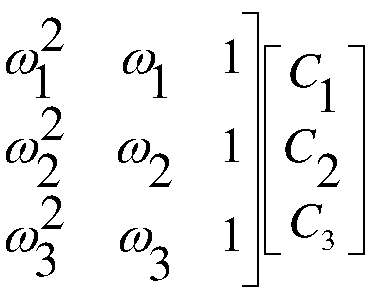
- the characteristic curve represents the constant wind volume physical characteristics that maintain control power and speed, based on the rated power range of all motors, for any type of air conditioning system designed for air conditioning systems, based on Power test results and speed curves, it can be concluded that a typical quadratic function can be well used to develop modeling as a typical function, P + xn + C ⁇ n 2 , by selecting on the curve
- the three to-be-determined points (A, B and C), the corresponding coordinates on the data are ( ⁇ , ⁇ ), ( ⁇ 2, ⁇ 2), ( ⁇ 3, ⁇ 3) take the coefficients Cl, C2, C3, see the following formula :
- the process of curve fitting is to select a polynomial to describe the curve, and the coefficients of the polynomial can be obtained by the least squares method.
- P C 1 + C 2 x n + C 3 x n 2 + ... + Cmxn m - 1
- P f(n) is a second order function: + ⁇ 2 , where Cl , ⁇ and ⁇ are coefficients, n is the motor speed value, and any one of the target air volumes tested corresponds to a set, C ⁇ PC 3 coefficient and stored, and the processor is based on the input.
- each target air volume corresponds to a group, ⁇ and ⁇ coefficients. The details are as shown in Table 1 below:
- Figure 10 is a plot of the experimental data of the direct power control of a 1 / 3 HP fan motor in a small pipe air conditioning system. For a given target airflow, the system selects some typical wind CFM as a test point to build a The database is used to build mathematical models. These typical points include the most Small and maximum air volume values, with some intermediate points added according to product specifications, typical air volume CFM as test points are 5, 150 I 300 I 450 / 600 and 750 CFM respectively
- Table 2 shows an example of the test data results.
- the speed of the motor ranges from 200 to 1400 rpm; the static pressure of the system ranges from 0.1 to 1 H 2 6». Maintain the preset constant air volume CCFM output and obtain a value corresponding to the motor input power of Figure 10 to form a database.
- each predetermined CFM wind volume corresponds to a quadratic function of power and speed, obtained in a standard calculation method:
- These equations define the power and the speed of the operating point of any system at a particular static pressure.
- the motor system defines a function corresponding to it, and the trajectory of its working point follows the function definition. Equations (3) through (7) can be expressed as a standard equation, and Cl C2 C3 is a constant.
- the modeling curve provides the trajectory of five selected operating points for several constant air volume CFM requirements, Power is power and n is speed.
- the matrix data is listed below.
- this direct power control DPC uses speed control for power control.
- the function of the power/speed control logic is to coordinate the power/speed loop time constant to ensure system stability. Control can be controlled by controlling the precise control of the motor and torque control. Whether in scalar or vector control, speed control is more effective than torque control. Improve control accuracy.
- DPC control is speed controlled through unique power and fan load speed characteristics.
- the motor rotates from zero to high speed, and the power is also increased from zero to increasing.
- the speed of the motor will rise until it reaches a pair of operating points A (power, speed), which is the static pressure point.
- A power, speed
- the algorithm will know if this is at a constant CFM trajectory curve operating point, thus determining a pair of power / Speed point "C;”. But point C is not a stable working point, due to the high power requirement, then go to the "D" point, repeat, and so on to converge to a new stable working point "G", ending.
- Figure 12 is a logic block diagram of the algorithm in the scalar control application of the fan motor.
- the input power is calculated from the DC bus voltage and current.
- the power and speed will be limited to the maximum power ⁇ and the speed /7.
- the real-time input power value Pi of the motor is calculated by the feedback DC bus current/voltage.
- the calculated value Pt of the motor input power is obtained, and the calculated value Pt of the motor input power is compared with
- the real-time output power Pi of the motor obtains the power difference ⁇ , and the power difference ⁇ is limited to avoid the power difference ⁇ being too large, and the adjustment power fluctuation is large.
- the power difference ⁇ is output through the power/speed control logic, and the speed loop is controlled.
- the PWM inverter performs the speed control.
- the principle of air volume measurement of fan motor is as follows:
- Figure 10 is the experimental data fitting curve of the direct power control constant air volume of the 1 / 3HP fan motor in the small pipe air conditioning system, the air volume CFM as the test point has 5, respectively 150, 300, At 450, 600, and 750 CFM, equations (3) through (7) are obtained.
- Table 2 shows an example of the test data results.
- the motor's speed range is from 200 to 1400 rpm; the system's static pressure is from 0.1 to 1H 2 6», and the preset constant air volume CCFM output is maintained to obtain a value corresponding to the motor input power of Figure 10.
- any air volume data that is no longer the above five working points.
- the matrix equation and calculate the Cl, C2, and C3 coefficients. Therefore, the power equation can be obtained for any required input air volume IN-CFM. That is, any input target air volume can get the constant air volume control letter corresponding to the target air volume.
- the speeds corresponding to the lines CFMI and CFM2 are respectively nl, n2, and the constant air volume value CFM0-CFM2+ (CFM1-CFM2) X (n2- no) ⁇ (n2-nl) of the point M (Po, no), where CFMK CFM2 is One of the air volumes 150, n (300), 450, 600, 750. From the above derivation, it can be known that the real-time power Po and the rotational speed no of the motor are known to obtain the air volume value CFM0 output by the air-conditioning system. When the deviation of the detected air volume is less than the set air volume, it is determined that the air filter is clogged and Output signal alarm.
- Embodiment 2 is a diagrammatic representation of Embodiment 1:
- a method for measuring air volume by a fan motor characterized in that: it comprises the following steps:
- CFM0 CFMi+ (CFMi- 1-CFMi) X (ni-no) ⁇ (ni- ni- 1). .
- F (n ) is obtained by: collecting the original data first, in the air duct equipment, for the M target air volume, from the low static pressure to the high static pressure, the static pressure can cover The actual static pressure range of the application, in the process of adjusting the static pressure, let the motor be
- the fan motor works in the constant speed control mode. When the deviation between the detected air volume and the set air volume reaches a certain value, it is judged that the air filter is clogged and alarmed. There are at least five M air volume points to ensure that the real-time detection air volume CFM0 is calculated. Precision.
- Embodiment 3 is a certain value.
- a method for measuring air volume by a fan motor characterized in that: it comprises the following steps:
- CFM0 CFMi+ (CFMi- 1-CFMi) X (ni-no) ⁇ (ni- ni- 1). .
- F (n ) The motor output torque Q is proportional to the operating current of the motor, so the motor output torque Q can be calculated by detecting the operating current of the motor.
- the fan motor works in the constant torque control mode. When the deviation between the detected air volume and the set air volume reaches a certain value, it is judged that the air filter is clogged and alarmed, and at least 5 M air volume points are used to ensure the meter.
Landscapes
- Engineering & Computer Science (AREA)
- Mechanical Engineering (AREA)
- General Engineering & Computer Science (AREA)
- Aviation & Aerospace Engineering (AREA)
- Physics & Mathematics (AREA)
- General Physics & Mathematics (AREA)
- Control Of Motors That Do Not Use Commutators (AREA)
- Control Of Positive-Displacement Air Blowers (AREA)
- Control Of Electric Motors In General (AREA)
Abstract
Description



Claims
Priority Applications (6)
| Application Number | Priority Date | Filing Date | Title |
|---|---|---|---|
| JP2016530183A JP6254276B2 (ja) | 2014-07-23 | 2014-07-23 | ファン・モータ風量の検出法 |
| CA2934585A CA2934585C (en) | 2014-07-23 | 2014-07-23 | Air volume measurement method for fan motor |
| MX2016007013A MX351652B (es) | 2014-07-23 | 2014-07-23 | Método de medición de volumen de aire para motor de ventilador. |
| KR1020167018552A KR101815408B1 (ko) | 2014-07-23 | 2014-07-23 | 팬 모터의 풍량 측정 방법 |
| PCT/CN2014/082814 WO2016011618A1 (zh) | 2014-07-23 | 2014-07-23 | 一种风机电机测量风量的方法 |
| US14/886,118 US10233933B2 (en) | 2014-07-23 | 2015-10-19 | Method for measuring air volume of blower motor |
Applications Claiming Priority (1)
| Application Number | Priority Date | Filing Date | Title |
|---|---|---|---|
| PCT/CN2014/082814 WO2016011618A1 (zh) | 2014-07-23 | 2014-07-23 | 一种风机电机测量风量的方法 |
Related Child Applications (1)
| Application Number | Title | Priority Date | Filing Date |
|---|---|---|---|
| US14/886,118 Continuation-In-Part US10233933B2 (en) | 2014-07-23 | 2015-10-19 | Method for measuring air volume of blower motor |
Publications (1)
| Publication Number | Publication Date |
|---|---|
| WO2016011618A1 true WO2016011618A1 (zh) | 2016-01-28 |
Family
ID=55162421
Family Applications (1)
| Application Number | Title | Priority Date | Filing Date |
|---|---|---|---|
| PCT/CN2014/082814 Ceased WO2016011618A1 (zh) | 2014-07-23 | 2014-07-23 | 一种风机电机测量风量的方法 |
Country Status (6)
| Country | Link |
|---|---|
| US (1) | US10233933B2 (zh) |
| JP (1) | JP6254276B2 (zh) |
| KR (1) | KR101815408B1 (zh) |
| CA (1) | CA2934585C (zh) |
| MX (1) | MX351652B (zh) |
| WO (1) | WO2016011618A1 (zh) |
Cited By (5)
| Publication number | Priority date | Publication date | Assignee | Title |
|---|---|---|---|---|
| CN108836628A (zh) * | 2018-04-23 | 2018-11-20 | 常州迅安科技股份有限公司 | 一种无传感器呼吸机及其恒定出风量控制方法 |
| CN111237980A (zh) * | 2020-01-09 | 2020-06-05 | 峰岹科技(深圳)有限公司 | 风机滤网堵塞的检测方法、装置及计算机可读存储介质 |
| TWI713988B (zh) * | 2019-02-01 | 2020-12-21 | 台灣日立江森自控股份有限公司 | 用於空調設備之馬達控制裝置及其馬達控制方法 |
| CN112985530A (zh) * | 2021-02-01 | 2021-06-18 | 南京航空航天大学 | 一种基于特征方程根轨迹的燃油计量装置设计参数调整方法 |
| WO2022193799A1 (zh) * | 2021-03-16 | 2022-09-22 | 合肥美的暖通设备有限公司 | 一种风机控制方法、装置及风机设备 |
Families Citing this family (10)
| Publication number | Priority date | Publication date | Assignee | Title |
|---|---|---|---|---|
| WO2018199928A1 (en) * | 2017-04-25 | 2018-11-01 | Hewlett-Packard Development Company, L.P. | Fluid impeller controller |
| CN107166671B (zh) * | 2017-06-15 | 2020-04-10 | 广东美的暖通设备有限公司 | 空调及其室内风机恒风量控制方法和控制装置及控制系统 |
| CN108870642A (zh) * | 2018-04-27 | 2018-11-23 | 苏州倍安电子科技有限公司 | 新风净化器滤网状态自校验方法 |
| US11143427B2 (en) | 2018-10-26 | 2021-10-12 | Johnson Controls Technology Company | Fan motor control |
| CN110469530B (zh) * | 2019-07-30 | 2024-06-14 | 广西电网有限责任公司电力科学研究院 | 电站锅炉轴流式引风机性能测试系统及其效率测试方法 |
| CN111426032B (zh) * | 2020-04-07 | 2022-02-11 | 广东美的暖通设备有限公司 | 运行控制方法、多联机空调器和存储介质 |
| DE102021202255A1 (de) * | 2021-03-09 | 2022-09-15 | BSH Hausgeräte GmbH | Verfahren und System zur Handhabung eines Lüfters einer Dunstabzugsvorrichtung |
| US11969679B2 (en) | 2021-03-19 | 2024-04-30 | Matthew Mashburn | Surface-enhanced copper filter for air purification and system and method for using |
| CN113486953B (zh) * | 2021-07-06 | 2024-10-15 | 茵梦达(上海)电气传动设备有限公司 | 变频器滤网更换时间的预测方法、装置及计算机可读介质 |
| CN119103670A (zh) * | 2024-08-28 | 2024-12-10 | 中山大洋电机股份有限公司 | 风量控制方法、装置、目标电机、存储介质及程序产品 |
Citations (6)
| Publication number | Priority date | Publication date | Assignee | Title |
|---|---|---|---|---|
| US5447414A (en) * | 1994-05-27 | 1995-09-05 | Emerson Electric Co. | Constant air flow control apparatus and method |
| US7567049B2 (en) * | 2006-04-21 | 2009-07-28 | Emerson Electric Co. | Fluid flow control for fluid handling systems |
| CN202013212U (zh) * | 2011-03-29 | 2011-10-19 | 东北电力科学研究院有限公司 | 变速或定速风机风量计算系统 |
| CN103376743A (zh) * | 2012-04-26 | 2013-10-30 | 中山大洋电机股份有限公司 | 一种电机及空调风机系统的恒风量控制方法 |
| WO2014024359A1 (ja) * | 2012-08-09 | 2014-02-13 | パナソニック株式会社 | モータ制御装置、モータ制御方法および送風装置 |
| CN104180858A (zh) * | 2014-07-23 | 2014-12-03 | 中山大洋电机股份有限公司 | 一种风机电机测量风量的方法 |
Family Cites Families (4)
| Publication number | Priority date | Publication date | Assignee | Title |
|---|---|---|---|---|
| JP3738685B2 (ja) | 2000-11-21 | 2006-01-25 | 三菱電機株式会社 | インバータ装置および送風装置 |
| US6504338B1 (en) * | 2001-07-12 | 2003-01-07 | Varidigm Corporation | Constant CFM control algorithm for an air moving system utilizing a centrifugal blower driven by an induction motor |
| JP5821565B2 (ja) * | 2011-11-21 | 2015-11-24 | 富士通株式会社 | 送風機制御装置、送風機制御方法および送風機制御プログラム |
| CN104521136B (zh) * | 2012-08-09 | 2017-03-29 | 松下知识产权经营株式会社 | 电动机控制装置、电动机控制方法以及送风装置 |
-
2014
- 2014-07-23 JP JP2016530183A patent/JP6254276B2/ja active Active
- 2014-07-23 KR KR1020167018552A patent/KR101815408B1/ko active Active
- 2014-07-23 CA CA2934585A patent/CA2934585C/en active Active
- 2014-07-23 WO PCT/CN2014/082814 patent/WO2016011618A1/zh not_active Ceased
- 2014-07-23 MX MX2016007013A patent/MX351652B/es active IP Right Grant
-
2015
- 2015-10-19 US US14/886,118 patent/US10233933B2/en active Active
Patent Citations (6)
| Publication number | Priority date | Publication date | Assignee | Title |
|---|---|---|---|---|
| US5447414A (en) * | 1994-05-27 | 1995-09-05 | Emerson Electric Co. | Constant air flow control apparatus and method |
| US7567049B2 (en) * | 2006-04-21 | 2009-07-28 | Emerson Electric Co. | Fluid flow control for fluid handling systems |
| CN202013212U (zh) * | 2011-03-29 | 2011-10-19 | 东北电力科学研究院有限公司 | 变速或定速风机风量计算系统 |
| CN103376743A (zh) * | 2012-04-26 | 2013-10-30 | 中山大洋电机股份有限公司 | 一种电机及空调风机系统的恒风量控制方法 |
| WO2014024359A1 (ja) * | 2012-08-09 | 2014-02-13 | パナソニック株式会社 | モータ制御装置、モータ制御方法および送風装置 |
| CN104180858A (zh) * | 2014-07-23 | 2014-12-03 | 中山大洋电机股份有限公司 | 一种风机电机测量风量的方法 |
Cited By (7)
| Publication number | Priority date | Publication date | Assignee | Title |
|---|---|---|---|---|
| CN108836628A (zh) * | 2018-04-23 | 2018-11-20 | 常州迅安科技股份有限公司 | 一种无传感器呼吸机及其恒定出风量控制方法 |
| CN108836628B (zh) * | 2018-04-23 | 2020-07-28 | 常州迅安科技股份有限公司 | 一种无传感器呼吸机及其恒定出风量控制方法 |
| TWI713988B (zh) * | 2019-02-01 | 2020-12-21 | 台灣日立江森自控股份有限公司 | 用於空調設備之馬達控制裝置及其馬達控制方法 |
| CN111237980A (zh) * | 2020-01-09 | 2020-06-05 | 峰岹科技(深圳)有限公司 | 风机滤网堵塞的检测方法、装置及计算机可读存储介质 |
| CN112985530A (zh) * | 2021-02-01 | 2021-06-18 | 南京航空航天大学 | 一种基于特征方程根轨迹的燃油计量装置设计参数调整方法 |
| WO2022193799A1 (zh) * | 2021-03-16 | 2022-09-22 | 合肥美的暖通设备有限公司 | 一种风机控制方法、装置及风机设备 |
| US12410807B2 (en) | 2021-03-16 | 2025-09-09 | Hefei Midea Heating & Ventilating Equipment Co., Ltd. | Method for controlling draught fan, and draught fan device |
Also Published As
| Publication number | Publication date |
|---|---|
| US10233933B2 (en) | 2019-03-19 |
| JP6254276B2 (ja) | 2017-12-27 |
| KR20160098345A (ko) | 2016-08-18 |
| CA2934585C (en) | 2017-10-17 |
| MX351652B (es) | 2017-10-24 |
| US20160040679A1 (en) | 2016-02-11 |
| JP2017500470A (ja) | 2017-01-05 |
| MX2016007013A (es) | 2016-09-07 |
| KR101815408B1 (ko) | 2018-01-30 |
| CA2934585A1 (en) | 2016-01-28 |
Similar Documents
| Publication | Publication Date | Title |
|---|---|---|
| WO2016011618A1 (zh) | 一种风机电机测量风量的方法 | |
| CN105444340B (zh) | 一种带滤网堵塞检测功能的电器设备 | |
| CN104180858B (zh) | 一种风机电机测量风量的方法 | |
| US10066631B2 (en) | Direct power control for constant airflow control | |
| CN104174238B (zh) | 一种送风设备的滤网堵塞检测方法及其应用的送风设备 | |
| CN105629814B (zh) | 一种具有抽风或者送风功能的电器设备的恒风量控制方法 | |
| CN104807152B (zh) | Pm电机直接功率控制的恒风量控制方法及其应用的hvac系统 | |
| US9732976B2 (en) | Direct power control for constant airflow control with advanced motor system modeling | |
| JP2017500470A5 (zh) | ||
| CN105378390B (zh) | 一种应用在hvac系统中的ecm电机的恒风量控制方法 | |
| WO2016155270A1 (zh) | 一种电器设备的通风管道堵塞程度实时显示控制方法 | |
| CN106160587B (zh) | 一种电机的控制方法及应用其的带有风道的电器设备的控制方法 | |
| WO2016011617A1 (zh) | 一种送风设备的滤网堵塞检测方法及其应用的送风设备 | |
| WO2016029532A1 (zh) | 一种空调系统 | |
| CN106152385B (zh) | 一种风机电机的控制方法及一种空调的控制方法 |
Legal Events
| Date | Code | Title | Description |
|---|---|---|---|
| 121 | Ep: the epo has been informed by wipo that ep was designated in this application |
Ref document number: 14898080 Country of ref document: EP Kind code of ref document: A1 |
|
| ENP | Entry into the national phase |
Ref document number: 2016530183 Country of ref document: JP Kind code of ref document: A |
|
| WWE | Wipo information: entry into national phase |
Ref document number: MX/A/2016/007013 Country of ref document: MX |
|
| ENP | Entry into the national phase |
Ref document number: 2934585 Country of ref document: CA |
|
| ENP | Entry into the national phase |
Ref document number: 20167018552 Country of ref document: KR Kind code of ref document: A |
|
| NENP | Non-entry into the national phase |
Ref country code: DE |
|
| 122 | Ep: pct application non-entry in european phase |
Ref document number: 14898080 Country of ref document: EP Kind code of ref document: A1 |