WO2016010034A1 - Micro-needle and micro-needle assembly - Google Patents
Micro-needle and micro-needle assembly Download PDFInfo
- Publication number
- WO2016010034A1 WO2016010034A1 PCT/JP2015/070157 JP2015070157W WO2016010034A1 WO 2016010034 A1 WO2016010034 A1 WO 2016010034A1 JP 2015070157 W JP2015070157 W JP 2015070157W WO 2016010034 A1 WO2016010034 A1 WO 2016010034A1
- Authority
- WO
- WIPO (PCT)
- Prior art keywords
- puncture
- surface defining
- protrusion
- microneedle
- puncture protrusion
- Prior art date
Links
Images


Classifications
-
- A—HUMAN NECESSITIES
- A61—MEDICAL OR VETERINARY SCIENCE; HYGIENE
- A61M—DEVICES FOR INTRODUCING MEDIA INTO, OR ONTO, THE BODY; DEVICES FOR TRANSDUCING BODY MEDIA OR FOR TAKING MEDIA FROM THE BODY; DEVICES FOR PRODUCING OR ENDING SLEEP OR STUPOR
- A61M37/00—Other apparatus for introducing media into the body; Percutany, i.e. introducing medicines into the body by diffusion through the skin
- A61M37/0015—Other apparatus for introducing media into the body; Percutany, i.e. introducing medicines into the body by diffusion through the skin by using microneedles
- A61M2037/0023—Drug applicators using microneedles
-
- A—HUMAN NECESSITIES
- A61—MEDICAL OR VETERINARY SCIENCE; HYGIENE
- A61M—DEVICES FOR INTRODUCING MEDIA INTO, OR ONTO, THE BODY; DEVICES FOR TRANSDUCING BODY MEDIA OR FOR TAKING MEDIA FROM THE BODY; DEVICES FOR PRODUCING OR ENDING SLEEP OR STUPOR
- A61M37/00—Other apparatus for introducing media into the body; Percutany, i.e. introducing medicines into the body by diffusion through the skin
- A61M37/0015—Other apparatus for introducing media into the body; Percutany, i.e. introducing medicines into the body by diffusion through the skin by using microneedles
- A61M2037/0053—Methods for producing microneedles
Definitions
- the present invention relates to a microneedle used for drug administration and a microneedle assembly including a microneedle and an applicator.
- a method using a microneedle As a method for administering a drug such as a vaccine into the body, a method using a microneedle is known (see, for example, Patent Documents 1 and 2).
- the microneedle has a plurality of puncture protrusions having a needle shape on the surface of the substrate.
- the puncture protrusion pierces the skin by pressing the substrate against the skin, and the drug is fed into the skin from the hole formed by the puncture protrusion. Since the length of the puncture protrusion is such that the tip of the puncture protrusion does not reach the nerve cells of the dermis layer in the skin, the administration method using microneedles is less than the administration method using injection needles. Pain is reduced when the is perforated.
- the administration method using microneedles since the drug is administered into the skin in which antigen-presenting cells are abundant, there is a possibility that the dose of the drug can be reduced as compared with subcutaneous injection.
- a microneedle assembly including a microneedle and an applicator that assists perforation of the skin by a puncture protrusion is used.
- the applicator supports the outer peripheral portion of the surface, which is the surface on which the puncture protrusion is formed, of the two surfaces of the base, and the puncture protrusion exposed from the applicator is used to pierce the skin through the applicator. A biasing force is given.
- the surface of the base described above may not be completely flat, for example, having a slight waviness or a slight curvature. Therefore, the length of the puncture protrusion exposed from the applicator can vary depending on which part of the surface of the substrate is supported by the applicator. As a result, for example, even if the length from the surface of the substrate to the tip of the puncture protrusion is measured in advance, the length of the puncture protrusion exposed from the applicator is not determined as one value with respect to the measured value.
- the stability of the puncture function of the puncture protrusion such as the length and quantity of the puncture protrusion that pierces the skin, the size of the hole formed by the perforation, and the like.
- improving the stability of the puncture function of the puncture protrusion is not limited to the microneedle used with the applicator, but is also a common requirement for microneedles in which the puncture protrusion is formed on the surface of the substrate.
- An object of the present invention is to provide a microneedle and a microneedle assembly that enhance the stability of a puncture function of a puncture protrusion when a drug is administered.
- a microneedle that solves the above problem includes a base having a first surface and a second surface that is opposite to the first surface, and a puncture protrusion protruding from the first surface of the base;
- a surface defining structure group including three or more surface defining structures each having a surface defining portion, wherein the surface defining structure is a surface defining projection protruding from the first surface and functioning as the surface defining portion
- the surface defining protrusion having a portion and the surface defining recess recessed from the first surface, the surface defining recess having a bottom functioning as the surface defining portion, and facing the first surface
- the surface defining structure has the surface defining structure group located on an outer peripheral portion that is a portion surrounding the puncture protrusion in the base, and the tip of the puncture protrusion is Any three of the surface defining structures in the surface defining structure group It protrudes beyond the plane containing the surface defining portion.
- the tip of the puncture protrusion protrudes from the plane including the surface defining portion of any three surface defining structures, and the length of the puncture protrusion protruding from the plane is determined with respect to the plane. Therefore, for example, since it is possible to determine the position of the applicator with respect to such a plane, the stability of the puncture function of the puncture protrusion portion is enhanced when a drug is administered.
- the surface defining structure may be the surface defining protrusion.
- regulation structure is a surface prescription
- regulated by a surface prescription structure is easy.
- the said structure WHEREIN It is preferable that the said surface prescription
- the said structure WHEREIN It is preferable that the said surface prescription
- the said structure WHEREIN It is preferable that the number of the said surface prescription
- the length of the surface defining structure in the thickness direction of the base body is preferably 1 ⁇ 4 or less of the length of the puncture protrusion in the thickness direction of the base body. According to the above configuration, the length of the portion of the puncture protrusion that protrudes beyond the plane defined by the surface defining structure can be ensured, and the portion that functions when the drug is administered in the puncture protrusion It is easy to ensure a large length.
- the microneedle includes a plurality of the puncture protrusions, and is in a region surrounded by a straight line connecting the surface defining structures adjacent to each other at the outer peripheral portion when viewed from the direction facing the first surface.
- the figure having the center of gravity is a target figure
- the plurality of puncture protrusions include the puncture protrusions arranged at the vertices of the target figure.
- the surface defining structure it is possible to prevent the surface defining structure from being disposed at a position deviated from the arrangement of the puncture protrusion. Therefore, since the position of the puncture protrusion is prevented from being biased with respect to the plane defined by the surface defining structure, the stability of the puncture function of the puncture protrusion is further improved when the drug is administered.
- the surface defining structure may be the surface defining recess. According to the above configuration, compared to the case where the surface defining structure is the surface defining protrusion, it is possible to ensure a large length of the portion of the puncture protrusion that protrudes beyond the plane defined by the surface defining structure. Yes, it is easy to ensure a large length of the portion that functions in the administration of the drug in the puncture protrusion.
- the said structure WHEREIN It is preferable that the said surface prescription
- the said structure WHEREIN It is preferable that the said surface prescription
- the said structure WHEREIN It is preferable that the number of the said surface prescription
- the microneedle includes a plurality of the puncture protrusions, and is in a region surrounded by a straight line connecting the surface defining structures adjacent to each other at the outer peripheral portion when viewed from the direction facing the first surface.
- the figure having the center of gravity is a target figure
- the plurality of puncture protrusions include the puncture protrusions arranged at the vertices of the target figure.
- the surface defining structure it is possible to prevent the surface defining structure from being disposed at a position deviated from the arrangement of the puncture protrusion. Therefore, since the position of the puncture protrusion is prevented from being biased with respect to the plane defined by the surface defining structure, the stability of the puncture function of the puncture protrusion is further improved when the drug is administered.
- a microneedle assembly that solves the above problems includes the microneedle and an applicator that includes a cylindrical portion, and the cylindrical portion includes two open ends and an in-cylinder space provided between the open ends.
- a support portion having a shape in which the base of the microneedle is accommodated in the in-cylinder space, and one of the two opening ends protrudes radially inward of the cylinder portion.
- the three surface defining portions included in the plane come into contact with the support portion, and the puncture protrusion protrudes from the opening end that is the support portion to the outside of the cylinder portion. To do.
- the tip of the puncture protrusion protrudes from the plane including the surface defining portion of any three surface defining structures, and the length of the puncture protrusion protruding from the plane is determined with respect to the plane. . And since the position of an applicator is defined with respect to such a plane, the stability of the puncture function which a puncture protrusion part has at the time of administration of a chemical
- the stability of the puncture function of the puncture protrusion of the microneedle can be improved during drug administration.
- FIG. 1 It is sectional drawing which shows the cross-section of the microneedle of one Embodiment. It is a top view which shows the planar structure of the microneedle of one Embodiment. It is a figure which shows the manufacturing process of the microneedle of one Embodiment, Comprising: It is a figure which shows the process in which an intaglio is produced from an original plate. It is a figure which shows the manufacturing process of the microneedle of one Embodiment, Comprising: It is a figure which shows the produced intaglio.
- microneedle and microneedle assembly will be described with reference to FIGS. [Configuration of microneedle]
- the configuration of the microneedle 10 will be described with reference to FIGS. 1 and 2.
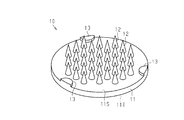
- the microneedle 10 includes a base 11 having a plate shape, a puncture protrusion 12 protruding from the base 11, and a non-puncture protrusion 13 that is an example of a surface defining protrusion protruding from the base 11. And.
- the surface defining protrusion is an example of a surface defining structure.
- the base 11, the puncture protrusion 12, and the non-puncture protrusion 13 are integrally formed.
- the base body 11 has, for example, a disk shape, and includes a first surface 11S that is a surface on which the puncture protrusion 12 is formed, and a second surface 11T that is a surface opposite to the first surface 11S. Yes.
- the non-puncture protrusion 13 is formed on the first surface 11S, and the first surface 11S supports the proximal end of the puncture protrusion 12 and the proximal end of the non-puncture protrusion 13. That is, the puncture protrusion 12 and the non-puncture protrusion 13 protrude in the same direction with respect to the base body 11.
- the 1st surface 11S and the 2nd surface 11T may not be a plane, and may have a level
- the first surface 11S is a surface constituting one end of the base 11 in the thickness direction
- the second surface 11T is a surface constituting the other end of the base 11 in the thickness direction. Good.
- the puncture protrusion 12 has a sufficient fineness and a tip angle for piercing the skin to which the drug is administered, and preferably has a sufficient length for allowing the drug to penetrate into the skin. . Therefore, it is preferable that the puncture protrusion 12 has a shape in which the cross-sectional area decreases toward the tip.
- the puncture protrusion 12 is formed in a conical shape or a pyramid shape.
- the puncture protrusion 12 may have a shape in which two or more solids are combined, such as a shape in which a cone is stacked on a cylinder. Note that a constriction or a step may be formed on the side wall of the puncture protrusion 12.
- the length Hn of the puncture protrusion 12 is the length from the first surface 11S to the tip of the puncture protrusion 12 in the thickness direction of the base 11, that is, in the direction orthogonal to the first surface 11S of the base 11.
- the length Hn of the puncture protrusion 12 is preferably a length that penetrates the stratum corneum, which is the outermost layer of the skin, and does not reach the nerve layer, and is specifically within a range of 0.05 mm or more and 3 mm or less. It is preferable that
- the width D of the puncture protrusion 12 in the direction along the first surface 11S is preferably in the range of 0.005 mm to 2 mm.
- the width D is the maximum length of the joint portion between the base body 11 and the puncture protrusion 12 in the cross section in the thickness direction of the base body 11, that is, the maximum of the bottom surface of the puncture protrusion 12 located in the first surface 11S. Length.
- the number of puncture protrusions 12 is arbitrary and may be one or more.
- the shape of the non-puncture protrusion 13 is not particularly limited, and the non-puncture protrusion 13 may be a cylindrical shape or a prismatic shape, or may be a cone shape or a pyramid shape.
- the tip of the non-puncture protrusion 13 preferably has higher flatness than the tip of the puncture protrusion 12, and the tip surface of the non-puncture protrusion 13 is more preferably flat. From such a viewpoint, it is preferable that the non-puncture protrusion 13 has a cylindrical shape or a prismatic shape.
- the length Ht of the non-puncture protrusion 13 is the length from the first surface 11S to the tip of the non-puncture protrusion 13 in the thickness direction of the base 11.
- the length Ht of the non-puncture protrusion 13 is smaller than the length Hn of the puncture protrusion 12.
- the length Ht of the non-puncture projection portion 13 is 1 ⁇ 4 or less of the length Hn of the puncture projection portion 12 in order to ensure a large portion of the puncture projection portion 12 that functions at the time of drug administration. It is preferable that
- the lower limit of the length Ht of the non-puncture protrusion 13 is not particularly limited, but the length Ht of the non-puncture protrusion 13 is greater than the bulge of the first surface 11S due to the undulation and unevenness that occur in the manufacturing process of the microneedle 10. Larger is preferred. From such a viewpoint, the length Ht of the non-puncture protrusion 13 is preferably 50 ⁇ m or more.
- variety of the non-puncture projection part 13 in the direction along the 1st surface 11S is not specifically limited.
- each of the plurality of puncture protrusions 12 may be regularly arranged on the first surface 11S of the base body 11, You may line up irregularly.
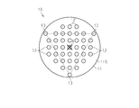
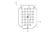
- the plurality of puncture protrusions 12 are arranged in a lattice shape or a concentric shape when viewed from the direction facing the first surface 11S.
- the puncture protrusions 12 are arranged in a lattice pattern within the octagonal region.
- the non-puncture protrusion 13 is disposed on the outer peripheral portion that is the portion surrounding the puncture protrusion 12 on the first surface 11S of the base 11. That is, the non-puncture protrusion 13 is disposed outside the region where the puncture protrusion 12 is disposed.
- the microneedle 10 has three non-puncture protrusions 13, and the puncture protrusion 12 protrudes from a plane including the tips of the three non-puncture protrusions 13. That is, the puncture protrusion 12 protrudes beyond the plane including the tips of the three non-puncture protrusions 13.
- the three non-puncture protrusions 13 constitute a non-puncture protrusion group which is an example of a surface defining structure group.
- the region surrounded by these straight lines is the target region.
- the center of gravity of the figure formed by linking the puncture protrusion 12 arranged on the outermost side in the area where the puncture protrusion 12 is arranged in the target area as viewed from the direction facing the first surface 11S Is preferably arranged.
- the puncture protrusion 12 is arranged at the vertex of the target figure.
- an octagonal center of gravity A formed by connecting the outermost puncture protrusions 12 is arranged in a triangular region consisting of a straight line connecting three non-puncture protrusions 13. ing.
- the plurality of non-puncture protrusions 13 are preferably arranged uniformly in the circumferential direction of the base body 11 on the outer peripheral portion of the first surface 11S.
- the administration method of the drug performed using the microneedle 10 is not particularly limited.
- the liquid drug is applied to the skin before or after the microneedle 10 is stabbed into the skin, and is formed by the puncture protrusion 12. From the hole, the drug may be fed into the skin.
- the drug when the drug is applied to the surface of the puncture protrusion 12 and the puncture protrusion 12 punctures the skin, the drug may be sent into the skin, or the puncture protrusion 12 includes the drug, and the puncture protrusion The drug may be fed into the skin by dissolving the puncture protrusion 12 in a state where 12 is stuck in the skin.
- a liquid medicine may be supplied from the outside of the microneedle 10 and the medicine may be sent into the skin through the puncture protrusion 12.
- the microneedle 10 is formed with a through-hole penetrating from the tip of the puncture protrusion 12 to the second surface 11T of the base 11, and the drug is fed into the skin from the through-hole.
- the kind of the drug is not particularly limited as long as it is a substance that functions by being administered intradermally.
- a pharmacologically active substance such as a vaccine or a cosmetic composition having a cosmetic effect is used.
- the administration target of a medicine is not specifically limited, What is necessary is just an animal including a person.
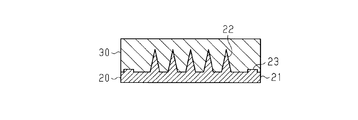
- FIG. 3 First, an original 20 of the microneedle 10 is manufactured.
- the original 20 includes a base 21 having the same outer shape as the base 11 of the microneedle 10 to be finally produced, and a first original protrusion 22 having the same shape and the same arrangement as the puncture protrusion 12 of the microneedle 10.
- a second original plate projection 23 having the same shape and the same arrangement as the non-puncture projection 13 of the microneedle 10.
- a large number of microneedles 10 having the same shape are produced from the original plate 20.
- the original plate 20 may also be used as a microneedle as a final product, like the microneedle 10 produced from the original plate 20.
- the original 20 is formed by cutting out or stacking the forming material of the original 20.
- the forming material may be ground by operating the inclined blade a plurality of times to form the first original plate protrusion 22 and the second original plate protrusion 23, or a precision machine using a 5-axis processing machine or the like.
- the master 20 may be produced by processing.
- the original material 20 may be manufactured by etching the forming material by etching such as dry etching or wet etching.
- the material for forming the original plate 20 is not particularly limited, and for example, metal, ceramics, silicon, glass, or the like is preferably used.
- the master 20 is preferably formed from a material having strength and biocompatibility necessary for skin perforation.
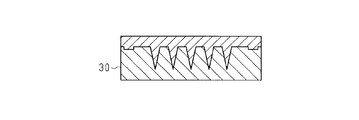
- the 2nd original projection part 23 may be produced separately from base 21 and the 1st original projection part 22, and the 2nd original projection part 23 may be fixed to base 21 by welding, adhesion, etc. Subsequently, the original plate 20 is molded and the intaglio plate 30 is produced.
- the intaglio 30 has a shape in which the unevenness of the original 20 is inverted.
- the material for forming the intaglio 30 is not particularly limited, and for example, a metal such as Ni or a resin such as silicon rubber is preferably used.
- the intaglio 30 is filled with the material for forming the microneedles 10.
- the material for forming the microneedles 10 is preferably a biocompatible material.
- the microneedle 10 is formed of a resin, the surface of the substrate 11 is likely to be undulated. Therefore, when the configuration of this embodiment is applied to such a microneedle 10, a high effect can be obtained.
- the resin material having biocompatibility include medical silicone, polylactic acid, polyglycolic acid, polycarbonate, PEEK material, and the like.
- the forming material is melted and filled in the intaglio 30.
- the forming material is a thermoplastic resin
- molding can be performed quickly by appropriately managing the temperature rise and temperature fall. At this time, the resin may be pressurized and pushed into the intaglio 30. As a result, molding can be performed in a shorter time.
- the microneedle 10 is obtained by peeling the filled molding from the intaglio 30.
- the surface of the molded product exposed from the intaglio 30 is sucked by a vacuum device, or an adhesive substance is adhered to the surface of the molded product exposed from the intaglio 30 to remove the molded product from the intaglio 30. It is done by tearing off. Or you may extrude a molding from the intaglio 30 using an ejector pin.
- the forming material and the manufacturing method of the microneedle 10 are not limited to the above-described examples.
- the forming material may be a metal such as stainless steel, titanium, manganese, or silicon, or a ceramic such as alumina, zirconia, silicon carbide, or silicon nitride, or the puncture protrusion 12 may contain a drug.
- a water-soluble polymer may be used as a forming material.
- the microneedle 10 should just be produced with the manufacturing method according to such formation material.
- the microneedle assembly 60 includes the microneedle 10 and the applicator 50 described above.
- the applicator 50 is a cylindrical portion 51 having two open ends, and includes a cylindrical portion 51 formed with an in-cylinder space sandwiched between the open ends, and the cylindrical portion 51 is arranged in the radial direction of the cylindrical portion 51.
- a support portion 52 that protrudes inward and forms one of the two open ends of the cylindrical portion 51 is provided.
- the base body 11 When the microneedle 10 and the applicator 50 are assembled, the base body 11 is accommodated in the in-cylinder space of the cylindrical part 51 with the first surface 11S of the base body 11 facing the support part 52. And the puncture projection part 12 protrudes outside the applicator 50 from the opening end which is the support part 52.
- the applicator 50 has a function of assisting skin perforation by the puncture protrusion 12.
- the applicator 50 may have a portion that functions as a handle when a person punctures the microneedle 10 into the skin, or a mechanism that applies a biasing force to the puncture protrusion 12 to pierce the skin. You may have.
- the outer shape of the region surrounded by the inner peripheral edge of the support portion 52 is smaller than the outer shape of the base body 11. And larger than the outer shape of the region where the puncture protrusion 12 is formed.
- the outer shape of the substrate 11 is circular
- the outer shape of the region surrounded by the inner peripheral edge of the support portion 52 is concentric with the outer circle of the substrate 11 and has a slightly smaller circle.
- substrate 11 in which the non-puncture protrusion part 13 is formed is covered with the support part 52.
- the puncture protrusion 12 protrudes from the region surrounded by the inner peripheral edge of the support portion 52 to the outside of the tube portion 51, and the tip of the non-puncture protrusion portion 13 is supported by the in-cylinder space of the tube portion 51.
- the part 52 is contacted. That is, the support part 52 is necessarily arranged on one plane including the tips of the three non-puncture protrusions 13.
- the plane including the tips of the three non-puncture projections 13 is defined as one, and this plane is the reference plane. Function as. The length from the reference plane to the tip of each puncture protrusion 12 is determined to be one value for each puncture protrusion 12.
- the position of the applicator 50 is determined with respect to the reference plane. Therefore, even when undulation or curvature is generated in the base body 11, the length of the puncture protrusion 12 protruding outside the applicator 50 does not change every time the microneedle 10 and the applicator 50 are assembled. Each part 12 is kept constant.
- the stability of the puncture function of the puncture protrusion 12 when the drug is administered is improved as a result of increasing the stability of the length and quantity of the puncture protrusion 12 that pierces the skin, the size of the hole formed by the perforation, and the like. .
- a reference length that is a length from the reference surface to the tip of the puncture protrusion 12 is obtained based on the length Hn of the puncture protrusion 12 and the length Ht of the non-puncture protrusion 13 in advance. Based on the reference length and the elements defined by the applicator such as the thickness of the support portion 52, the length of the puncture protrusion 12 protruding outside the applicator 50 can be obtained.
- the micro-needle 10 is set with the reference plane as a reference in the pre-processing and post-processing apparatus. It is preferable to be installed at a position. According to such a configuration, the length of the puncture protrusion 12 used for pre-processing and post-processing is set so that each puncture protrusion 12 is installed in the apparatus depending on the installation state of the microneedle 10 in the apparatus. Change is suppressed.
- the effects listed below can be obtained.
- the plane including the tips of the three non-puncture protrusions 13 is defined as one, and this reference
- the length of the puncture protrusion 12 protruding from the surface is determined with respect to the reference surface.
- medical agent is improved.
- the reference plane is precisely defined as one.
- the first surface 11S of the base body 11 has a slight swell or a slight curvature, and is not completely flat.
- the length of the puncture protrusion 12 exposed from the applicator 50 can vary depending on which part of the first surface 11S of the base 11 the support portion 52 of the applicator 50 contacts. Therefore, before attaching the microneedle to the applicator 50, an inspection process for inspecting the length and variation of the puncture protrusion 12 exposed from the applicator 50 is performed, and the length and variation of the puncture protrusion 12 become the reference values.
- the length and variation of the puncture protrusion 12 vary depending on the occasion of attaching the microneedle to the applicator 50, and thus such selection is difficult.
- the length of the portion protruding from the reference surface in the puncture protrusion 12 is defined as one.
- the position of the applicator 50 with respect to such a reference surface is determined, and the length of the portion protruding from the reference surface is used for the inspection, so that the puncture protrusion exposed from the applicator 50 before mounting the microneedle on the applicator 50 It is possible to easily select microneedles in which the length of the portion 12 and variations thereof do not satisfy the reference value.
- the microneedle 10 having the non-puncture protrusion 13 can be easily manufactured.
- the tip of the non-puncture protrusion 13 has higher flatness than the tip of the puncture protrusion 12, measuring the position of the tip of the non-puncture protrusion 13 can It is easier than measuring the position of the tip. Therefore, it becomes easy to define a plane including the tips of the three non-puncture protrusions 13.
- the distal end surface of the non-puncture protrusion 13 is a flat surface, it becomes easier to measure the position of the non-puncture protrusion 13. Further, since the non-puncture protrusion 13 is in contact with the support portion 52 of the applicator 50 in a plane, the stability of the position of the microneedle 10 and the applicator 50 when the microneedle 10 is assembled with the applicator 50 is used. Enhanced.
- the non-puncture protrusion 13 and the applicator 50 are disposed outside the region where the puncture protrusion 12 is disposed with respect to the arrangement of the puncture protrusion 12. Therefore, the stability of the position of the puncture protrusion 12 protruding outside the applicator 50 is improved.
- the puncture protrusion part 12 The stability of the position is further increased.
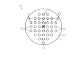
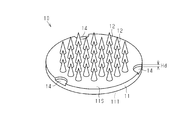
- the plurality of non-puncture protrusions 13 may not be evenly arranged in the circumferential direction of the base body 11 on the outer peripheral portion of the first surface 11S. According to such a configuration, when the microneedle 10 is manufactured or used, the microneedle 10 can be positioned using the arrangement of the plurality of non-puncture protrusions 13 as an alignment mark. Even when the plurality of non-puncture protrusions 13 are not evenly arranged, a straight line connecting the non-puncture protrusions 13 adjacent to each other at the outer peripheral portion of the base body 11 when viewed from the direction facing the first surface 11S.
- the puncture protrusion 12 is arranged at the apex of the target graphic which is a graphic having a center of gravity in the target region.
- the puncture protrusion 12 is not arranged at the vertex of the subject graphic having the center of gravity, the effect (1) can be obtained.
- the plurality of non-puncture protrusions 13 may include a non-puncture protrusion 13 having a shape different from that of the other non-puncture protrusions 13.
- the shapes of 13 may be different from each other.
- one non-puncture protrusion 13 is formed in a column shape having an elliptical cross section, and the two non-puncture protrusions 13 have a cross section. Is formed in a columnar shape having a circular shape. According to such a configuration, when the microneedle 10 is manufactured or used, the microneedle 10 can be positioned using the non-puncture protrusion 13 as an alignment mark.
- the non-puncture protrusion 13 may be in contact with the outer edge of the first surface 11 ⁇ / b> S of the base 11. That is, a part of the outer edge of the non-puncture protrusion 13 and a part of the outer edge of the base body 11 may overlap each other when viewed from the direction facing the first surface 11S.
- the support portion 52 of the applicator 50 is disposed so as to come into contact with the tip of the non-puncture protrusion 13 and not into the first surface 11S of the base body 11.
- the non-puncture protrusion 13 may include a non-puncture protrusion 13 having a length Ht different from that of the other non-puncture protrusion 13, and the length Ht of the plurality of non-puncture protrusions 13 may be May be different from each other.
- the length Hn of the plurality of puncture protrusions 12 tends to be smaller as it is closer to a predetermined portion, the closer to the predetermined portion is, the closer to the length Ht of the plurality of non-puncture protrusions 13 is. A small tendency may be given. With such a configuration, it is possible to adjust the distribution of the length of the puncture protrusion 12 that functions when the drug is administered.
- the tip surface of the non-puncture protrusion 13 may be a curved surface.
- the non-puncture protrusion 13 may have a conical shape, and at this time, the tip of the non-puncture protrusion 13 preferably has a larger radius of curvature than the tip of the puncture protrusion 12.
- one reference plane is defined by the tips of the three non-puncture protrusions 13. Even if the tip of the non-puncture protrusion 13 does not have higher flatness than the tip of the puncture protrusion 12, one reference plane is defined by the tips of the three non-puncture protrusions 13.
- the outer shape of the base body 11 is not limited to a circle, but may be a polygonal shape.
- the cylindrical portion 51 of the applicator 50 has a cylindrical shape in which the inner peripheral edge of the cross section is similar to the outer shape of the base body 11.
- the support portion 52 covers the outer peripheral portion of the base body 11, that is, the outside of the region where the puncture projection portion 12 is formed, and contacts the non-puncture projection portion 13.
- the number of non-puncture protrusions 13 constituting the non-puncture protrusion group may be 4 or more, and is preferably 3 or more and 5 or less. At this time, it is preferable that 3 or more and 5 or less non-puncture protrusions 13 are dispersed over the entire outer peripheral portion of the first surface 11S. However, it is most preferable that the number of the non-puncture protrusions 13 distributed over the entire outer peripheral portion of the first surface 11S is three as in the above embodiment.
- any three non-puncture protrusions 13 among the plurality of non-puncture protrusions 13 are set, and each of the plurality of planes It is sufficient that the puncture protrusion 12 protrudes.
- the number of non-puncture protrusions 13 constituting the non-puncture protrusion group is 3 or more and 5 or less, any three of the non-puncture protrusions 13 can be compared with the configuration having more than five. Since the number of planes including the tip of the non-puncture protrusion 13 is small, it is easy to define such planes.
- the non-puncture protrusion 13 constituting the non-puncture protrusion group is configured to be distributed and arranged over the entire outer peripheral portion of the first surface 11S, the non-puncture protrusion 13 is biased to a part of the outer peripheral portion. Compared to the configuration, it is also possible to reflect the overall shape of the outer peripheral portion with respect to the defined plane.
- one plane is selected as the reference plane from these planes.
- a plane in which the length of the puncture protrusion 12 that functions during drug administration is closest to the desired length is selected as the reference plane, and the three non-puncture protrusions 13 constituting this plane constitute the reference plane.
- the non-puncture protrusion 13 is selected.
- the support portion 52 of the applicator 50 is provided at a position in contact with the three non-puncture protrusions 13 arranged at a predetermined position on the outer peripheral portion of the base 11, and the non-puncture is at a position other than the predetermined position.
- the protrusion 13 may be configured not to contact the support portion 52.
- one plane is selected as a reference plane from among a plurality of planes defined by the plurality of non-puncture protrusions 13.
- the position of the support portion 52 may be changed depending on the type of the applicator 50, and the three non-puncture protrusions 13 constituting the reference surface may be changed for each type of the applicator 50.
- the base body 11 is pressed against the support portion 52 and is relatively long among the plurality of non-puncture protrusion portions 13.
- Non-puncture projections 13 other than the three non-puncture projections 13 having a long length Ht also contact the support portion 52.
- the area that receives the load applied to the microneedles 10 from the support 52 is increased by the microneedles 10 due to pressing, so It is possible to prevent deformation such as deflection from occurring in the microneedle 10.
- the non-puncture protrusion 13 may be arranged at a position different from the outer peripheral portion of the base body 11 in addition to the outer peripheral portion of the base body 11.
- the base 11, the puncture protrusion 12 and the non-puncture protrusion 13 are integrally formed.
- the non-puncture protrusion 13 is formed separately from the base 11 and the puncture protrusion 12, and the base 11 may be fixed to the first surface 11S.
- the non-puncture protrusion 13 is formed of a material conforming to the base 11 and the puncture protrusion 12 such as a biocompatible metal or resin, and is fixed to the first surface 11S by adhesion or the like. According to such a configuration, since it becomes easy to change the shape and arrangement of the non-puncture protrusion 13 for each microneedle 10, the shape and arrangement of the non-puncture protrusion 13 can be easily adjusted.
- the surface defining structure is a protrusion protruding from the first surface 11S of the base body 11, that is, the non-puncture protrusion 13, and the tip of the non-puncture protrusion 13 defines a plane.
- the surface defining structure constituting the surface defining structure group is a structure having a height difference with respect to the first surface 11S, and one plane is defined by points included in the respective surfaces of the three surface defining structures. Any structure can be used as long as it can be defined.
- the surface defining structure may be a recess 14 that is a surface defining recess recessed from the first surface 11 ⁇ / b> S of the base 11.
- the bottom part of the recessed part 14 functions as a surface defining part.
- the support part 52 of the applicator 50 assembled with the microneedle 10 having such a configuration is, for example, a protrusion part that protrudes toward the first surface 11S from the surface of the support member 52 that faces the first surface 11S.
- a protrusion part and the bottom part of the recessed part 14 will contact.
- the support part 52 is necessarily arranged on one plane including the bottoms of the three recesses 14. Also with such a configuration, the length of the puncture protrusion 12 protruding beyond the reference plane defined by the bottoms of the three recesses 14 is determined with respect to the reference plane. For this reason, the stability of the puncture function of the puncture protrusion 12 at the time of drug administration is enhanced.
- the bottom of the recess 14 preferably has higher flatness than the tip of the puncture protrusion 12, as shown in FIG.
- the bottom of the recess 14 is preferably a flat surface.
- the arrangement of the recesses 14 may be the same arrangement as in the case where the surface defining structure is the non-puncture protrusion 13 as exemplified in the embodiment and the modification, but the following arrangement is particularly preferable.
- the recess 14 is disposed at a position along the outer edge of the base 11, and a part of the outer edge of the recess 14 and the outer edge of the base 11 are viewed from the direction facing the first surface 11 ⁇ / b> S. It overlaps with a part of.
- the support portion 52 of the applicator 50 needs to be disposed so as to be in contact with the bottom of the recess 14 and not in contact with the first surface 11S of the base body 11.
- the depth Hd of the concave portion 14 that is the length from the first surface 11S to the bottom of the concave portion 14 in the thickness direction of the base 11 is that of the first surface 11S due to the undulations and irregularities that occur in the manufacturing process of the microneedle 10. It is preferably larger than the dent. From such a viewpoint, the depth Hd of the recess 14 is preferably 50 ⁇ m or more.
- the number of recesses 14 constituting the surface defining structure group is preferably 3 or more and 5 or less, as in the case where the surface defining structure is the non-puncture protrusion 13. At this time, it is preferable that three or more and five or less recesses 14 are dispersed over the entire outer peripheral portion of the base 11. Furthermore, it is preferable that the number of the concave portions 14 dispersedly arranged on the entire outer peripheral portion of the base 11 is three.
- the surface defining structure is the non-puncture protrusion 13, as viewed from the direction facing the first surface 11 ⁇ / b> S of the base body 11, the region surrounded by a straight line connecting the concave portions 14 adjacent to each other at the outer peripheral portion.
- the puncture protrusion 12 is arranged at the vertex of the target figure.
- the surface defining structure is the non-puncture protrusion 13 protruding from the first surface 11S of the base body 11
- the surface defining structure is the recess 14 recessed from the first surface 11S
- the surface defining structure is compared. Is the non-puncture protrusion 13 because it is easy to measure the length of the puncture protrusion 12 protruding from the reference surface, and it is easy to form the surface defining portion flat.
- the surface defining structure is the concave portion 14 it is possible to ensure a large portion of the puncture protrusion 12 that protrudes beyond the reference surface, and it is easy to ensure a large length of the portion that functions when the drug is administered. .
- the original plate 20 of the microneedle 10 was produced. Quartz was used as a forming material of the original plate 20, and the original plate 20 was produced by cutting out from the base material using a 5-axis processing machine.
- the first original plate protrusions 22 are arranged in a total of 37 pieces of 5 rows ⁇ 5 rows and three on each of the upper, lower, left and right sides of the 5 rows ⁇ 5 rows square. ing. That is, as shown in FIG. 2, the first original plate protrusions 22 are arranged in a lattice pattern in an octagonal region.
- the first original projection 22 has a conical shape, the length of the first original projection 22 is 900 ⁇ m, and the width of the first original projection 22 is 400 ⁇ m.
- the pitch between the first original plate protrusions 22 adjacent to each other is 700 ⁇ m, the outer shape of the base 21 is a circle having a diameter of 6.2 mm, and the thickness of the base 21 is 1000 ⁇ m.
- the shape of the second original projection 23 in the original 20 is a columnar shape, and the second original projection 23 has a flat surface at the tip.
- the length of the second original projection 23 is 100 ⁇ m, and the width of the second original projection 23 is 400 ⁇ m.
- the number of the second original projections 23 is three. As shown in FIG. 2, the three second original projections 23 are evenly arranged in the circumferential direction of the base 21 on the outer periphery of the base 21. Is arranged.
- the shapes of the three second original plate projections 23 are all the same.
- an intaglio 30 was produced from the original 20. Specifically, a Ni layer was formed on the surface of the original plate 20 by Ni electroforming, and the original plate 20 was removed by hydrofluoric acid to produce an intaglio plate 30 made of Ni.
- PGA which is one of biodegradable resins for medical use was placed on the intaglio plate 30 as a material for forming the microneedle 10 and heated to 250 ° C. to melt the PGA.
- the amount of PGA was adjusted according to the shape of the microneedle 10 and the thickness of the substrate 11 that were the purpose of production.
- PGA was pressurized from above with a silicon rubber roller, and the PGA was pushed into the intaglio 30.
- the intaglio 30 filled with PGA was cooled from above and below, and after the temperature of the intaglio 30 dropped to near room temperature, vacuum tweezers were attached to the back of the molding, and the molding was peeled off from the intaglio 30. At this time, it is preferable to peel off the molded product perpendicularly to the intaglio plate 30 in order to suppress the bending or bending of the tip of the puncture protrusion 12.
- the puncture protrusion 12 is disposed at a position corresponding to the first original protrusion 22 of the original 20 described above, the length Hn of the puncture protrusion 12 is 900 ⁇ m, the width D of the puncture protrusion 12 is 400 ⁇ m, and the base 11 A microneedle having a thickness of 400 ⁇ m was obtained.
- Three columnar non-puncture projections 13 are arranged on the outer peripheral portion of the first surface 11S of the base 11 at positions corresponding to the second master projections 23 in the master 20, and these three non-puncture projections are arranged. The portions 13 were evenly arranged in the circumferential direction of the base 11, and the length Ht of the non-puncture protrusion 13 was 100 ⁇ m.
- the microneedle 10 of the example was assembled to the applicator 50 to obtain the microneedle assembly 60 of the example.
- the applicator 50 includes a cylindrical tube portion 51 and a support portion 52.
- the tube portion 51 has an inner diameter of 6.2 mm
- the support portion 52 has an inner diameter of 5 mm
- the support portion 52 has an inner diameter.
- the thickness was 300 ⁇ m.
- the non-puncture protrusion 13 comes into contact with the support portion 52 inside the cylindrical portion 51, and the support portion is formed on one plane including the tips of the three non-puncture protrusion portions 13. 52 was placed.
- the distribution of the length of the puncture protrusion 12 protruding from the applicator 50 can be calculated based on the distribution of the length Hn of the puncture protrusion 12 and the length Ht of the non-puncture protrusion 13 measured in advance. did it.
- the length of the puncture protrusion 12 protruding from the applicator 50 was 500 ⁇ m.
Abstract
Description
上記構成によれば、面規定構造が面規定凹部である場合と比較して、面規定構造によって規定される上記平面から突き出た穿刺突起部の長さの計測が容易である。 In the above configuration, the surface defining structure may be the surface defining protrusion.
According to the said structure, compared with the case where a surface prescription | regulation structure is a surface prescription | regulation recessed part, the measurement of the length of the puncture protrusion part which protruded from the said plane prescribed | regulated by a surface prescription structure is easy.
上記構成によれば、面規定部の位置を計測することが、穿刺突起部の先端の位置を計測することよりも容易である。それゆえに、任意の3つの面規定構造の面規定部を含む平面を規定することが容易になる。 The said structure WHEREIN: It is preferable that the said surface prescription | regulation part has flatness higher than the front-end | tip of the said puncture protrusion part.
According to the above configuration, measuring the position of the surface defining part is easier than measuring the position of the tip of the puncture protrusion. Therefore, it becomes easy to define a plane including the surface defining portions of any three surface defining structures.
上記構成によれば、面規定構造の数量が5つよりも多い構成と比べて、任意の3つの面規定構造の面規定部を含む平面を規定することが容易であり、また、面規定構造群を構成する面規定構造が外周部の一部に偏る構成と比較して、規定される平面に対して外周部の全体形状を反映させることが可能でもある。それゆえに、薬剤の投与に際して、穿刺突起部が有する穿刺機能の安定性がさらに高められる。 The said structure WHEREIN: It is preferable that the said surface prescription | regulation structure group contains the said surface prescription | regulation structure of 3-5 below distributed over the said outer peripheral part.
According to the above configuration, it is easier to define a plane including the surface defining portions of any three surface defining structures, compared to a configuration having more than five surface defining structures, and the surface defining structure Compared with a configuration in which the surface defining structure constituting the group is biased to a part of the outer peripheral portion, it is possible to reflect the entire shape of the outer peripheral portion on the defined plane. Therefore, the stability of the puncture function of the puncture protrusion is further enhanced when the drug is administered.
上記構成によれば、面規定構造による平面の規定が容易であり、こうした平面が的確に1つに規定される。 The said structure WHEREIN: It is preferable that the number of the said surface prescription | regulation structure distributed over the said outer peripheral part is three.
According to the above configuration, it is easy to define a plane by the surface defining structure, and such a plane is precisely defined as one.
上記構成によれば、穿刺突起部のなかで、面規定構造によって規定される平面を超えて突き出る部分の長さを大きく確保可能であり、穿刺突起部のなかで、薬剤の投与に際して機能する部分の長さを大きく確保しやすい。 In the above configuration, the length of the surface defining structure in the thickness direction of the base body is preferably ¼ or less of the length of the puncture protrusion in the thickness direction of the base body.
According to the above configuration, the length of the portion of the puncture protrusion that protrudes beyond the plane defined by the surface defining structure can be ensured, and the portion that functions when the drug is administered in the puncture protrusion It is easy to ensure a large length.
上記構成によれば、面規定構造が面規定突起部である場合と比較して、穿刺突起部のなかで、面規定構造によって規定される平面を超えて突き出る部分の長さを大きく確保可能であり、穿刺突起部のなかで、薬剤の投与に際して機能する部分の長さを大きく確保しやすい。 In the above configuration, the surface defining structure may be the surface defining recess.
According to the above configuration, compared to the case where the surface defining structure is the surface defining protrusion, it is possible to ensure a large length of the portion of the puncture protrusion that protrudes beyond the plane defined by the surface defining structure. Yes, it is easy to ensure a large length of the portion that functions in the administration of the drug in the puncture protrusion.
上記構成によれば、面規定部が平面であるため、面規定部の位置を計測することが容易である。また、面規定構造によって規定される平面上にアプリケーターが配置される場合には、マイクロニードルとアプリケーターとの位置の安定性が高められる。 The said structure WHEREIN: It is preferable that the said surface prescription | regulation part is a plane.
According to the above configuration, since the surface defining portion is a flat surface, it is easy to measure the position of the surface defining portion. In addition, when the applicator is arranged on a plane defined by the surface defining structure, the stability of the positions of the microneedle and the applicator is enhanced.
上記構成によれば、面規定構造の数量が5つよりも多い構成と比べて、任意の3つの面規定構造の面規定部を含む平面を規定することが容易であり、また、面規定構造群を構成する面規定構造が外周部の一部に偏る構成と比較して、規定される平面に対して外周部の全体形状を反映させることが可能でもある。それゆえに、薬剤の投与に際して、穿刺突起部が有する穿刺機能の安定性がさらに高められる。 The said structure WHEREIN: It is preferable that the said surface prescription | regulation structure group contains the said surface prescription | regulation structure of 3-5 below distributed over the said outer peripheral part.
According to the above configuration, it is easier to define a plane including the surface defining portions of any three surface defining structures, compared to a configuration having more than five surface defining structures, and the surface defining structure Compared with a configuration in which the surface defining structure constituting the group is biased to a part of the outer peripheral portion, it is possible to reflect the entire shape of the outer peripheral portion on the defined plane. Therefore, the stability of the puncture function of the puncture protrusion is further enhanced when the drug is administered.
上記構成によれば、面規定構造による平面の規定が容易であり、こうした平面が的確に1つに規定される。 The said structure WHEREIN: It is preferable that the number of the said surface prescription | regulation structure distributed over the said outer peripheral part is three.
According to the above configuration, it is easy to define a plane by the surface defining structure, and such a plane is precisely defined as one.
[マイクロニードルの構成]
図1および図2を参照して、マイクロニードル10の構成について説明する。 One embodiment of a microneedle and microneedle assembly will be described with reference to FIGS.
[Configuration of microneedle]
The configuration of the microneedle 10 will be described with reference to FIGS. 1 and 2.
図2に示されるように、マイクロニードル10が複数の穿刺突起部12を有する場合、複数の穿刺突起部12の各々は、基体11の第1面11Sに規則的に並んでいてもよいし、不規則に並んでいてもよい。例えば、複数の穿刺突起部12は、第1面11Sと対向する方向から見て、格子状や同心円状に配列される。図2では、八角形状の領域内に、穿刺突起部12は格子状に配列されている。 In addition, the magnitude | size of the width | variety of the
As shown in FIG. 2, when the microneedle 10 has a plurality of
こうしたマイクロニードル10を用いて行われる薬剤の投与方式は特に限定されず、例えば、マイクロニードル10が皮膚に刺される前あるいは後に、液状の薬剤が皮膚に塗布され、穿刺突起部12によって形成された孔から、薬剤が皮内に送り込まれてもよい。あるいは、穿刺突起部12の表面に薬剤が塗布され、穿刺突起部12が皮膚を刺したときに、薬剤が皮内に送り込まれてもよいし、穿刺突起部12が薬剤を含み、穿刺突起部12が皮膚に刺さった状態で穿刺突起部12が溶解することにより、薬剤が皮内に送り込まれてもよい。またあるいは、マイクロニードル10の外部から、液状の薬剤が供給され、穿刺突起部12を通じて薬剤が皮内に送り込まれる方式であってもよい。この場合、マイクロニードル10には、穿刺突起部12の先端から基体11の第2面11Tまでを貫通する貫通孔が形成され、貫通孔から薬剤が皮内に送り込まれる。 In particular, when the
The administration method of the drug performed using the
図3~図6を参照して、上述のマイクロニードル10の製造方法について説明する。
図3に示されるように、まず、マイクロニードル10の原版20が作製される。原版20は、最終的に作製されるマイクロニードル10の基体11と同一の外形を有する基体21と、上記マイクロニードル10の穿刺突起部12と同一の形状および同一の配置の第1原版突起部22と、上記マイクロニードル10の非穿刺突起部13と同一の形状および同一の配置の第2原版突起部23とを有している。この原版20から、互いに同一な形状を有するマイクロニードル10が大量に作製される。 [Manufacturing method of microneedle]
With reference to FIG. 3 to FIG. 6, a manufacturing method of the above-described
As shown in FIG. 3, first, an original 20 of the microneedle 10 is manufactured. The original 20 includes a base 21 having the same outer shape as the
原版20は、原版20の形成材料の削り出しや積み上げによって形成される。例えば、傾斜ブレードが複数回操作されることにより形成材料が研削されて、第1原版突起部22や第2原版突起部23が形成されてもよいし、5軸加工機等を用いた精密機械加工によって、原版20が作製されてもよい。あるいは、ドライエッチングやウェットエッチング等のエッチングによって形成材料がエッチングされて、原版20が作製されてもよい。 The
The original 20 is formed by cutting out or stacking the forming material of the original 20. For example, the forming material may be ground by operating the inclined blade a plurality of times to form the first
続いて、原版20の型取りが行われ、凹版30が作製される。 In addition, the 2nd
Subsequently, the
マイクロニードル10の形成材料は、生体適合性を有する材料であることが好ましい。特に、マイクロニードル10が樹脂から形成される場合、基体11の表面にうねりが生じやすいため、こうしたマイクロニードル10に本実施形態の構成が適用されると、高い効果が得られる。生体適合性を有する樹脂材料としては、医療用シリコーン、ポリ乳酸、ポリグリコール酸、ポリカーボネート、あるいは、PEEK材等が挙げられる。 As shown in FIG. 5, subsequently, the
The material for forming the
図7および図8を参照して、マイクロニードルアセンブリーの構成を説明しつつ、本実施形態のマイクロニードルおよびマイクロニードルアセンブリーがもたらす作用について説明する。 [Configuration of microneedle assembly]
With reference to FIGS. 7 and 8, the configuration of the microneedle assembly will be described, and the effects of the microneedle and the microneedle assembly of this embodiment will be described.
(1)基体11の第1面11Sにおける外周部に、3つの非穿刺突起部13が配置されているため、3つの非穿刺突起部13の先端を含む平面が1つに規定され、この基準面から突き出た穿刺突起部12の長さが、当該基準面に対して定まる。そして、こうした基準面に対してアプリケーター50の位置を定めることが可能となるため、薬剤の投与に際して穿刺突起部12が有する穿刺機能の安定性が高められる。特に、非穿刺突起部13の数が3つであるため、基準面が的確に1つに規定される。 As described above, according to the microneedle and the microneedle assembly of the present embodiment, the effects listed below can be obtained.
(1) Since the three
(2)非穿刺突起部13の先端は、穿刺突起部12の先端よりも高い平坦性を有しているため、非穿刺突起部13の先端の位置を計測することが、穿刺突起部12の先端の位置を計測することよりも容易である。それゆえに、3つの非穿刺突起部13の先端を含む平面を規定することが容易になる。 Moreover, since the
(2) Since the tip of the
上記実施形態は、以下のように変更して実施することが可能である。
・図9に示されるように、複数の非穿刺突起部13は、第1面11Sにおける外周部上にて、基体11の周方向に均等に配置されていなくてもよい。こうした構成によれば、マイクロニードル10の製造時や使用時に、複数の非穿刺突起部13の配置をアライメントマークとして用いて、マイクロニードル10の位置決めを行うこともできる。複数の非穿刺突起部13が均等に配置されていない場合であっても、第1面11Sと対向する方向から見て、基体11の外周部にて互いに隣接する非穿刺突起部13を結ぶ直線で囲まれる領域を対象領域とするとき、対象領域内に重心を有した図形である対象図形の頂点には穿刺突起部12が配置されていることが好ましい。なお、上記重心を有した対象図形の頂点に穿刺突起部12が配置されていなくても、上記(1)の効果は得ることができる。 [Modification]
The above embodiment can be implemented with the following modifications.
As shown in FIG. 9, the plurality of
・上記実施形態では、基体11と穿刺突起部12と非穿刺突起部13とが一体に形成されたが、非穿刺突起部13は、基体11および穿刺突起部12とは別に形成されて、基体11の第1面11Sに固定されてもよい。非穿刺突起部13は、生体適合性を有する金属や樹脂等の、基体11および穿刺突起部12に準じた材料から形成され、接着等によって、第1面11Sに固定される。こうした構成によれば、マイクロニードル10ごとに、非穿刺突起部13の形状や配置を変更することが容易となるため、非穿刺突起部13の形状や配置の調整を容易に行うことができる。 The
In the above embodiment, the
上述したマイクロニードルおよびマイクロニードルアセンブリーについて、具体的な実施例を用いて説明する。 [Example]
The above-described microneedle and microneedle assembly will be described using specific examples.
まず、マイクロニードル10の原版20を作製した。原版20の形成材料としては、石英を用い、5軸加工機を用いて基材から削り出すことによって、原版20を作製した。 [Production of microneedles]
First, the
実施例のマイクロニードル10を、アプリケーター50に組み付けて、実施例のマイクロニードルアセンブリー60を得た。アプリケーター50は、先の図7に示されるように、円筒状の筒部51と支持部52とを備え、筒部51の内径は6.2mm、支持部52の内径は5mm、支持部52の厚みは300μmであった。 [Production of microneedle assembly]
The
Claims (13)
- 第1面と、前記第1面とは反対側の面である第2面とを有する基体と、
前記基体の前記第1面から突き出た穿刺突起部と、
面規定部をそれぞれ有する3以上の面規定構造を含む面規定構造群であって、前記面規定構造は、前記第1面から突き出た面規定突起部であって前記面規定部として機能する先端部を有する前記面規定突起部、および、前記第1面から窪んだ面規定凹部であって前記面規定部として機能する底部を有する前記面規定凹部のいずれかであり、前記第1面と対向する方向から見て、前記面規定構造は、前記基体にて前記穿刺突起部を囲う部分である外周部に位置する、前記面規定構造群と、を有し、
前記穿刺突起部の先端は、前記面規定構造群における任意の3つの前記面規定構造の前記面規定部を含む平面を越えて突き出ている
マイクロニードル。 A base body having a first surface and a second surface opposite to the first surface;
A puncture protrusion protruding from the first surface of the substrate;
A surface defining structure group including three or more surface defining structures each having a surface defining portion, wherein the surface defining structure is a surface defining projection protruding from the first surface and functioning as the surface defining portion The surface defining protrusion having a portion and the surface defining recess recessed from the first surface, the surface defining recess having a bottom functioning as the surface defining portion, and facing the first surface When viewed from the direction, the surface defining structure has the surface defining structure group located on an outer peripheral portion that is a portion surrounding the puncture protrusion in the base body,
The tip of the puncture protrusion protrudes beyond a plane including the surface defining portion of any three of the surface defining structures in the surface defining structure group. - 前記面規定構造は、前記面規定突起部である
請求項1に記載のマイクロニードル。 The microneedle according to claim 1, wherein the surface defining structure is the surface defining protrusion. - 前記面規定部は、前記穿刺突起部の先端よりも高い平坦性を有している
請求項2に記載のマイクロニードル。 The microneedle according to claim 2, wherein the surface defining portion has higher flatness than a tip of the puncture protrusion. - 前記面規定構造群は、前記外周部の全体に分散配置された3以上5以下の前記面規定構造を含む
請求項2または3に記載のマイクロニードル。 The microneedle according to claim 2 or 3, wherein the surface defining structure group includes 3 or more and 5 or less of the surface defining structures distributed over the entire outer peripheral portion. - 前記外周部の全体に分散配置された前記面規定構造の数は3である
請求項4に記載のマイクロニードル。 The microneedle according to claim 4, wherein the number of the surface defining structures distributed and arranged over the entire outer peripheral portion is three. - 前記基体の厚さ方向における前記面規定構造の長さは、前記基体の厚さ方向における前記穿刺突起部の長さの1/4以下である
請求項2~5のいずれか一項に記載のマイクロニードル。 The length of the surface defining structure in the thickness direction of the base body is ¼ or less of the length of the puncture protrusion in the thickness direction of the base body. Microneedle. - 複数の前記穿刺突起部を備え、
前記第1面と対向する方向から見て、前記外周部にて互いに隣接する前記面規定構造を結ぶ直線で囲まれる領域内に重心を有する図形が対象図形であって、前記複数の穿刺突起部は、前記対象図形の頂点に配置された前記穿刺突起部を含む
請求項2~6のいずれか一項に記載のマイクロニードル。 A plurality of puncture protrusions,
A figure having a center of gravity in a region surrounded by a straight line connecting the surface defining structures adjacent to each other at the outer peripheral part when viewed from the direction facing the first surface is a target figure, and the plurality of puncture protrusions The microneedle according to any one of claims 2 to 6, wherein the microneedle includes the puncture protrusion disposed at a vertex of the target graphic. - 前記面規定構造は、前記面規定凹部である
請求項1に記載のマイクロニードル。 The microneedle according to claim 1, wherein the surface defining structure is the surface defining recess. - 前記面規定部は平面である
請求項8に記載のマイクロニードル。 The microneedle according to claim 8, wherein the surface defining portion is a flat surface. - 前記面規定構造群は、前記外周部の全体に分散配置された3以上5以下の前記面規定構造を含む
請求項8または9に記載のマイクロニードル。 10. The microneedle according to claim 8, wherein the surface defining structure group includes 3 or more and 5 or less of the surface defining structures distributed over the entire outer peripheral portion. - 前記外周部の全体に分散配置された前記面規定構造の数は3である
請求項10に記載のマイクロニードル。 The microneedle according to claim 10, wherein the number of the surface defining structures distributed and arranged over the entire outer peripheral portion is three. - 複数の前記穿刺突起部を備え、
前記第1面と対向する方向から見て、前記外周部にて互いに隣接する前記面規定構造を結ぶ直線で囲まれる領域内に重心を有する図形が対象図形であって、前記複数の穿刺突起部は、前記対象図形の頂点に配置された前記穿刺突起部を含む
請求項8~11のいずれか一項に記載のマイクロニードル。 A plurality of puncture protrusions,
A figure having a center of gravity in a region surrounded by a straight line connecting the surface defining structures adjacent to each other at the outer peripheral part when viewed from the direction facing the first surface is a target figure, and the plurality of puncture protrusions The microneedle according to any one of claims 8 to 11, including the puncture protrusion disposed at the apex of the target graphic. - 請求項1~12のいずれか一項に記載のマイクロニードルと、
筒部を備えるアプリケーターと、
を備え、
前記筒部は、2つの開口端と、これらの開口端の間に設けられる筒内空間とを有し、
前記マイクロニードルの前記基体は前記筒内空間に収容され、前記2つの開口端のうちの一方の開口端は、前記筒部の径方向内側に向かって張り出した形状を有する支持部であり、前記筒内空間において、前記平面に含まれる前記3つの面規定部は前記支持部に接触し、前記穿刺突起部は、前記支持部である前記開口端から前記筒部の外側に突出する
マイクロニードルアセンブリー。 The microneedle according to any one of claims 1 to 12,
An applicator comprising a tubular portion;
With
The cylindrical portion has two open ends and an in-cylinder space provided between the open ends,
The base body of the microneedle is accommodated in the in-cylinder space, and one of the two opening ends is a support portion having a shape projecting radially inward of the cylinder portion, In the in-cylinder space, the three surface defining parts included in the flat surface are in contact with the support part, and the puncture protrusion part protrudes outside the cylinder part from the opening end that is the support part. Lee.
Priority Applications (4)
| Application Number | Priority Date | Filing Date | Title |
|---|---|---|---|
| EP15821366.0A EP3170528A4 (en) | 2014-07-15 | 2015-07-14 | Micro-needle and micro-needle assembly |
| JP2016534445A JP6658524B2 (en) | 2014-07-15 | 2015-07-14 | Microneedle and microneedle assembly |
| CN201580037386.6A CN106535980A (en) | 2014-07-15 | 2015-07-14 | Micro-needle and micro-needle assembly |
| US15/404,345 US10537722B2 (en) | 2014-07-15 | 2017-01-12 | Microneedle and microneedle assembly |
Applications Claiming Priority (2)
| Application Number | Priority Date | Filing Date | Title |
|---|---|---|---|
| JP2014145140 | 2014-07-15 | ||
| JP2014-145140 | 2014-07-15 |
Related Child Applications (1)
| Application Number | Title | Priority Date | Filing Date |
|---|---|---|---|
| US15/404,345 Continuation US10537722B2 (en) | 2014-07-15 | 2017-01-12 | Microneedle and microneedle assembly |
Publications (1)
| Publication Number | Publication Date |
|---|---|
| WO2016010034A1 true WO2016010034A1 (en) | 2016-01-21 |
Family
ID=55078524
Family Applications (1)
| Application Number | Title | Priority Date | Filing Date |
|---|---|---|---|
| PCT/JP2015/070157 WO2016010034A1 (en) | 2014-07-15 | 2015-07-14 | Micro-needle and micro-needle assembly |
Country Status (5)
| Country | Link |
|---|---|
| US (1) | US10537722B2 (en) |
| EP (1) | EP3170528A4 (en) |
| JP (1) | JP6658524B2 (en) |
| CN (1) | CN106535980A (en) |
| WO (1) | WO2016010034A1 (en) |
Cited By (3)
| Publication number | Priority date | Publication date | Assignee | Title |
|---|---|---|---|---|
| JP2018042856A (en) * | 2016-09-15 | 2018-03-22 | 凸版印刷株式会社 | Transdermal administration device manufacturing method and transdermal administration device |
| EP3366345A1 (en) * | 2017-02-28 | 2018-08-29 | FUJIFILM Corporation | Manufacturing method of sheet having needle-like protrusions |
| CN109152914A (en) * | 2016-05-31 | 2019-01-04 | 日写株式会社 | Microneedle array and its manufacturing method |
Families Citing this family (4)
| Publication number | Priority date | Publication date | Assignee | Title |
|---|---|---|---|---|
| EP3603508A1 (en) * | 2018-08-03 | 2020-02-05 | PKvitality | Multi-position capsule |
| CN111298281A (en) * | 2018-12-11 | 2020-06-19 | 尹忠 | Drug delivery microneedle and special production template for drug delivery microneedle |
| CN111298280B (en) * | 2018-12-11 | 2024-04-12 | 尹忠 | Soft back microneedle and manufacturing method thereof |
| CN117295535A (en) * | 2021-06-09 | 2023-12-26 | 花王株式会社 | injection needle |
Citations (5)
| Publication number | Priority date | Publication date | Assignee | Title |
|---|---|---|---|---|
| JP2009061144A (en) * | 2007-09-07 | 2009-03-26 | Toppan Printing Co Ltd | Acicular body chip and its manufacturing method |
| JP2012055343A (en) * | 2010-09-03 | 2012-03-22 | Toray Eng Co Ltd | Microneedle sheet and method for manufacturing the same |
| JP2013094224A (en) * | 2011-10-28 | 2013-05-20 | Toppan Printing Co Ltd | Microneedle device and method of manufacturing the same |
| JP3185527U (en) * | 2013-05-27 | 2013-08-22 | コスメディ製薬株式会社 | Board end face shape |
| WO2013151044A1 (en) * | 2012-04-05 | 2013-10-10 | 久光製薬株式会社 | Puncture device and method for manufacturing same |
Family Cites Families (13)
| Publication number | Priority date | Publication date | Assignee | Title |
|---|---|---|---|---|
| DK1432466T3 (en) * | 2001-09-12 | 2012-12-03 | Becton Dickinson Co | Micro needle-based pen dispenser for drug delivery and method of use thereof |
| US20050203575A1 (en) * | 2004-03-15 | 2005-09-15 | Unilever Home & Personal Care Usa, Division Of Conopco, Inc. | Skin microactivation system and method |
| JP2006341089A (en) | 2005-05-13 | 2006-12-21 | Fujikura Ltd | Instrument for carrying medicinal material and manufacturing method of the same |
| JP2006345983A (en) | 2005-06-14 | 2006-12-28 | Nabtesco Corp | Needle assembly for skin |
| US20070004989A1 (en) * | 2005-06-29 | 2007-01-04 | Parvinder Dhillon | Device for transdermal sampling |
| CN101267896A (en) * | 2005-09-12 | 2008-09-17 | 阿尔扎公司 | Coatable transdermal delivery microprojection assembly |
| JP4978245B2 (en) * | 2007-03-08 | 2012-07-18 | 凸版印刷株式会社 | Needle-shaped body, needle-shaped body manufacturing method, and drug transport device |
| JP5285943B2 (en) * | 2008-03-28 | 2013-09-11 | 凸版印刷株式会社 | Needle-shaped body array and method for manufacturing needle-shaped body array |
| US8888757B2 (en) * | 2009-05-27 | 2014-11-18 | Wisconsin Alumni Research Foundation | Active microneedle array |
| US20120184916A1 (en) * | 2009-08-07 | 2012-07-19 | Medrx Co., Ltd. | Applicator device of pinholder type microneedle |
| DE102011089723A1 (en) * | 2011-12-23 | 2013-06-27 | Robert Bosch Gmbh | Microneedle array applicator and method of applying a microneedle array |
| JP2013236865A (en) * | 2012-05-17 | 2013-11-28 | Tss Co Ltd | Hypodermic injection device and method for manufacturing the same |
| WO2017064870A1 (en) * | 2015-10-15 | 2017-04-20 | 凸版印刷株式会社 | Administration instrument |
-
2015
- 2015-07-14 JP JP2016534445A patent/JP6658524B2/en active Active
- 2015-07-14 CN CN201580037386.6A patent/CN106535980A/en active Pending
- 2015-07-14 EP EP15821366.0A patent/EP3170528A4/en active Pending
- 2015-07-14 WO PCT/JP2015/070157 patent/WO2016010034A1/en active Application Filing
-
2017
- 2017-01-12 US US15/404,345 patent/US10537722B2/en not_active Expired - Fee Related
Patent Citations (5)
| Publication number | Priority date | Publication date | Assignee | Title |
|---|---|---|---|---|
| JP2009061144A (en) * | 2007-09-07 | 2009-03-26 | Toppan Printing Co Ltd | Acicular body chip and its manufacturing method |
| JP2012055343A (en) * | 2010-09-03 | 2012-03-22 | Toray Eng Co Ltd | Microneedle sheet and method for manufacturing the same |
| JP2013094224A (en) * | 2011-10-28 | 2013-05-20 | Toppan Printing Co Ltd | Microneedle device and method of manufacturing the same |
| WO2013151044A1 (en) * | 2012-04-05 | 2013-10-10 | 久光製薬株式会社 | Puncture device and method for manufacturing same |
| JP3185527U (en) * | 2013-05-27 | 2013-08-22 | コスメディ製薬株式会社 | Board end face shape |
Non-Patent Citations (1)
| Title |
|---|
| See also references of EP3170528A4 * |
Cited By (3)
| Publication number | Priority date | Publication date | Assignee | Title |
|---|---|---|---|---|
| CN109152914A (en) * | 2016-05-31 | 2019-01-04 | 日写株式会社 | Microneedle array and its manufacturing method |
| JP2018042856A (en) * | 2016-09-15 | 2018-03-22 | 凸版印刷株式会社 | Transdermal administration device manufacturing method and transdermal administration device |
| EP3366345A1 (en) * | 2017-02-28 | 2018-08-29 | FUJIFILM Corporation | Manufacturing method of sheet having needle-like protrusions |
Also Published As
| Publication number | Publication date |
|---|---|
| EP3170528A1 (en) | 2017-05-24 |
| JP6658524B2 (en) | 2020-03-04 |
| US20170120027A1 (en) | 2017-05-04 |
| EP3170528A4 (en) | 2018-03-21 |
| JPWO2016010034A1 (en) | 2017-04-27 |
| CN106535980A (en) | 2017-03-22 |
| US10537722B2 (en) | 2020-01-21 |
Similar Documents
| Publication | Publication Date | Title |
|---|---|---|
| JP6658524B2 (en) | Microneedle and microneedle assembly | |
| JP5839603B2 (en) | Transdermal delivery device | |
| JP6074889B2 (en) | Micro needle tip | |
| JP6724792B2 (en) | Transdermal administration device | |
| US10086183B2 (en) | Applicator | |
| Lee | Fabrication of microneedle array using inclined LIGA process | |
| US10245354B2 (en) | Method for manufacturing hollow needle-shaped body, and hollow needle-shaped body | |
| JP7020399B2 (en) | Transdermal administration device | |
| US10596040B2 (en) | Transdermal administration device | |
| JP7394576B2 (en) | fine protrusions | |
| JP2019218318A (en) | Micro needle sheet | |
| US20180200495A1 (en) | Administration device | |
| JP6581010B2 (en) | Microneedle array | |
| JP6662177B2 (en) | Transdermal administration device container | |
| JP6476799B2 (en) | Method of manufacturing needle-like body | |
| JP2015231476A (en) | Needle-like body pad | |
| JP5931130B2 (en) | Microneedle array manufacturing method and injection mold used therefor | |
| JP2021007449A (en) | Microneedle | |
| CN116474254A (en) | Hierarchical microneedle patch and processing method | |
| JP2018042856A (en) | Transdermal administration device manufacturing method and transdermal administration device | |
| KR20110121244A (en) | Hollow type microneedle for easy mass production and manufacturing method thereof | |
| JP2018121842A (en) | Method for manufacturing needle-like body |
Legal Events
| Date | Code | Title | Description |
|---|---|---|---|
| 121 | Ep: the epo has been informed by wipo that ep was designated in this application |
Ref document number: 15821366 Country of ref document: EP Kind code of ref document: A1 |
|
| REEP | Request for entry into the european phase |
Ref document number: 2015821366 Country of ref document: EP |
|
| WWE | Wipo information: entry into national phase |
Ref document number: 2015821366 Country of ref document: EP |
|
| ENP | Entry into the national phase |
Ref document number: 2016534445 Country of ref document: JP Kind code of ref document: A |
|
| NENP | Non-entry into the national phase |
Ref country code: DE |