WO2016009729A1 - 撮像制御装置、撮像装置および撮像制御方法 - Google Patents
撮像制御装置、撮像装置および撮像制御方法 Download PDFInfo
- Publication number
- WO2016009729A1 WO2016009729A1 PCT/JP2015/065576 JP2015065576W WO2016009729A1 WO 2016009729 A1 WO2016009729 A1 WO 2016009729A1 JP 2015065576 W JP2015065576 W JP 2015065576W WO 2016009729 A1 WO2016009729 A1 WO 2016009729A1
- Authority
- WO
- WIPO (PCT)
- Prior art keywords
- image signal
- sensitivity
- low
- short
- pixel
- Prior art date
- Legal status (The legal status is an assumption and is not a legal conclusion. Google has not performed a legal analysis and makes no representation as to the accuracy of the status listed.)
- Ceased
Links
Images





Classifications
-
- G—PHYSICS
- G03—PHOTOGRAPHY; CINEMATOGRAPHY; ANALOGOUS TECHNIQUES USING WAVES OTHER THAN OPTICAL WAVES; ELECTROGRAPHY; HOLOGRAPHY
- G03B—APPARATUS OR ARRANGEMENTS FOR TAKING PHOTOGRAPHS OR FOR PROJECTING OR VIEWING THEM; APPARATUS OR ARRANGEMENTS EMPLOYING ANALOGOUS TECHNIQUES USING WAVES OTHER THAN OPTICAL WAVES; ACCESSORIES THEREFOR
- G03B15/00—Special procedures for taking photographs; Apparatus therefor
-
- H—ELECTRICITY
- H04—ELECTRIC COMMUNICATION TECHNIQUE
- H04N—PICTORIAL COMMUNICATION, e.g. TELEVISION
- H04N23/00—Cameras or camera modules comprising electronic image sensors; Control thereof
- H04N23/70—Circuitry for compensating brightness variation in the scene
- H04N23/72—Combination of two or more compensation controls
-
- H—ELECTRICITY
- H04—ELECTRIC COMMUNICATION TECHNIQUE
- H04N—PICTORIAL COMMUNICATION, e.g. TELEVISION
- H04N23/00—Cameras or camera modules comprising electronic image sensors; Control thereof
- H04N23/10—Cameras or camera modules comprising electronic image sensors; Control thereof for generating image signals from different wavelengths
- H04N23/11—Cameras or camera modules comprising electronic image sensors; Control thereof for generating image signals from different wavelengths for generating image signals from visible and infrared light wavelengths
-
- H—ELECTRICITY
- H04—ELECTRIC COMMUNICATION TECHNIQUE
- H04N—PICTORIAL COMMUNICATION, e.g. TELEVISION
- H04N23/00—Cameras or camera modules comprising electronic image sensors; Control thereof
- H04N23/70—Circuitry for compensating brightness variation in the scene
- H04N23/71—Circuitry for evaluating the brightness variation
-
- H—ELECTRICITY
- H04—ELECTRIC COMMUNICATION TECHNIQUE
- H04N—PICTORIAL COMMUNICATION, e.g. TELEVISION
- H04N23/00—Cameras or camera modules comprising electronic image sensors; Control thereof
- H04N23/70—Circuitry for compensating brightness variation in the scene
- H04N23/73—Circuitry for compensating brightness variation in the scene by influencing the exposure time
-
- H—ELECTRICITY
- H04—ELECTRIC COMMUNICATION TECHNIQUE
- H04N—PICTORIAL COMMUNICATION, e.g. TELEVISION
- H04N23/00—Cameras or camera modules comprising electronic image sensors; Control thereof
- H04N23/70—Circuitry for compensating brightness variation in the scene
- H04N23/741—Circuitry for compensating brightness variation in the scene by increasing the dynamic range of the image compared to the dynamic range of the electronic image sensors
-
- H—ELECTRICITY
- H04—ELECTRIC COMMUNICATION TECHNIQUE
- H04N—PICTORIAL COMMUNICATION, e.g. TELEVISION
- H04N25/00—Circuitry of solid-state image sensors [SSIS]; Control thereof
- H04N25/50—Control of the SSIS exposure
- H04N25/57—Control of the dynamic range
- H04N25/58—Control of the dynamic range involving two or more exposures
- H04N25/587—Control of the dynamic range involving two or more exposures acquired sequentially, e.g. using the combination of odd and even image fields
- H04N25/589—Control of the dynamic range involving two or more exposures acquired sequentially, e.g. using the combination of odd and even image fields with different integration times, e.g. short and long exposures
-
- H—ELECTRICITY
- H04—ELECTRIC COMMUNICATION TECHNIQUE
- H04N—PICTORIAL COMMUNICATION, e.g. TELEVISION
- H04N5/00—Details of television systems
- H04N5/222—Studio circuitry; Studio devices; Studio equipment
- H04N5/262—Studio circuits, e.g. for mixing, switching-over, change of character of image, other special effects ; Cameras specially adapted for the electronic generation of special effects
- H04N5/265—Mixing
-
- H—ELECTRICITY
- H04—ELECTRIC COMMUNICATION TECHNIQUE
- H04N—PICTORIAL COMMUNICATION, e.g. TELEVISION
- H04N2209/00—Details of colour television systems
- H04N2209/04—Picture signal generators
- H04N2209/041—Picture signal generators using solid-state devices
- H04N2209/042—Picture signal generators using solid-state devices having a single pick-up sensor
- H04N2209/047—Picture signal generators using solid-state devices having a single pick-up sensor using multispectral pick-up elements
Definitions
- the present technology relates to an imaging control device, an imaging device, and an imaging control method. Specifically, an imaging control device, an imaging device, and an imaging control method for generating an image with an expanded dynamic range by combining two images obtained by two shootings, and a program for causing a computer to execute the method About.
- the imaging device when shooting an object with a large luminance difference between a bright part and a dark part in an imaging device such as a camera, the imaging device is configured by performing multiple shootings with different exposure conditions and combining the obtained images.
- a system has been proposed in which an exposure condition is obtained from a histogram obtained by the first shooting and shooting is performed (see, for example, Patent Document 1).
- the above-described conventional technique has a problem that an appropriate exposure condition cannot be obtained in the second shooting.
- the image signal corresponding to the region where the luminance of the subject is high is often saturated at the time of the first shooting, the histogram obtained from such an image signal is completely different from the luminance distribution in the subject. Does not match. Therefore, when the second shooting is performed under the exposure conditions obtained from such a histogram, the obtained image is unnecessarily exposed.
- the present technology has been created in view of such a situation, and when generating an image with an expanded dynamic range by combining a plurality of images obtained by two shootings, the technique is also appropriate for the second shooting.
- An object is to obtain an appropriate exposure condition.
- the present technology has been made in order to solve the above-described problems.
- the first aspect of the present technology is that a normal pixel that generates an image signal and a low-sensitivity image signal are generated and visible light is generated more than the normal pixel.
- an exposure control unit that controls an image sensor having low-sensitivity pixels with low photoelectric conversion sensitivity under predetermined exposure conditions to output the image signal and the low-sensitivity image signal to the image sensor.
- a low-sensitivity histogram generation unit that generates a low-sensitivity histogram representing the appearance frequency distribution of the low-sensitivity image signal, and calculates a short-time exposure condition having an exposure time shorter than the exposure condition based on the generated low-sensitivity histogram And a short-time exposure that is an image signal generated by the normal pixel by controlling the imaging element according to the calculated short-time exposure condition.
- the short exposure control unit for outputting an image signal to the image pickup device, an image pickup control apparatus for and a synthesizing unit for synthesizing the image signal and the short-exposure image signal. This brings about the effect of calculating short-time exposure conditions with a short exposure time based on the low sensitivity histogram based on the low sensitivity image signal.
- a normal sensitivity histogram generation unit that generates a normal sensitivity histogram representing an appearance frequency distribution of the image signal based on the image signal, and the shortness based on the generated normal sensitivity histogram.
- You may further comprise the control part which makes a time exposure control part perform the said control.
- the second aspect of the present technology provides an imaging element including a normal pixel that generates an image signal and a low-sensitivity pixel that generates a low-sensitivity image signal and has a lower photoelectric conversion sensitivity to visible light than the normal pixel;
- An image pickup control device for controlling the image pickup device, wherein the image pickup control device controls the image pickup device according to a predetermined exposure condition to output the image signal and the low-sensitivity image signal to the image pickup device.
- a low-sensitivity histogram generation unit that generates a low-sensitivity histogram representing an appearance frequency distribution of the low-sensitivity image signal based on the low-sensitivity image signal, and the exposure condition based on the generated low-sensitivity histogram
- a short-time exposure condition calculation unit for calculating a short-time exposure condition with a short exposure time, and the normal pixel controlled by the image-capturing element according to the calculated short-time exposure condition
- the product short-exposure image signal is an image signal of an image pickup apparatus comprising: a short-time exposure control unit for output to the imaging device, and a synthesizing unit for synthesizing the image signal and the short-exposure image signal.
- an infrared light cut filter for blocking infrared light is further provided, the normal pixel is a visible light pixel corresponding to visible light, and the low-sensitivity pixel is infrared light. Infrared light pixels corresponding to may be used. This brings about the effect
- a predetermined imaging element including a normal pixel that generates an image signal and a low-sensitivity pixel that generates a low-sensitivity image signal and has a lower photoelectric conversion sensitivity to visible light than the normal pixel.
- composition of an imaging device in an embodiment of this art. It is a figure showing an example of composition of an image sensor in an embodiment of this art. It is a figure which shows an example of the spectral characteristic of the color filter of a pixel used for the image pick-up element in embodiment of this technique, and an infrared-light cut filter. It is a figure which shows an example of the characteristic of the pixel in an image pick-up element at the time of using the infrared-light cut filter in embodiment of this technique. It is a figure showing an example of composition of an imaging device in an embodiment of this art. It is a figure explaining the exposure control in the embodiment of this art and the calculation method of short-time exposure conditions. It is a figure which shows an example of the process sequence of the imaging control process in embodiment of this technique. It is a figure showing an example of a processing procedure of dynamic range expansion processing in an embodiment of this art.
- FIG. 1 is a diagram illustrating a configuration example of an imaging device according to an embodiment of the present technology.
- the imaging apparatus 10 in the figure includes a lens 100, an infrared light cut filter 200, an imaging element 300, and an imaging control apparatus 400.
- the lens 100 optically forms a subject on the image sensor 300.
- the infrared light cut filter 200 blocks infrared light included in the light incident on the image sensor 300.
- the image sensor 300 converts an optical image formed by the lens 100 into an image signal and outputs the image signal.
- pixels that generate image signals are two-dimensionally arranged on a surface on which an optical image is formed.
- This pixel includes a photoelectric conversion element that performs photoelectric conversion, and outputs an electrical signal corresponding to the luminance of light incident on the pixel.
- the image sensor includes an A / D converter, which converts this electric signal into a digital signal and outputs it as an image signal.
- the imaging device 300 includes a normal pixel that generates an image signal and a low-sensitivity pixel that generates a low-sensitivity image signal and has a lower photoelectric conversion sensitivity to visible light than the normal pixel. Yes.
- the configuration of the image sensor 300, normal pixels, and low-sensitivity pixels will be described later.
- the imaging control device 400 controls imaging in the imaging element 300.
- the imaging control device 400 also processes the image signal and low-sensitivity image signal output from the imaging element 300. These will be described later.
- the imaging control apparatus 400 also controls the entire imaging apparatus.
- the imaging apparatus 10 also includes a diaphragm (not shown) that changes the amount of light incident on the imaging element 300.
- FIG. 2 is a diagram illustrating a configuration example of the imaging element according to the embodiment of the present technology.
- the figure shows a configuration of a pixel surface, which is a surface on which pixels of the image sensor 300 are arranged. Pixels 301 are arranged in a two-dimensional lattice pattern on this pixel surface.
- R, G, B, and IR attached to the pixel 301 represent the type of the pixel 301.
- R represents a pixel corresponding to red light (R pixel)
- G represents a pixel corresponding to green light (G pixel)
- B represents a pixel corresponding to blue light (B pixel)
- IR represents infrared light Represents a pixel (IR pixel) corresponding to.
- a photoelectric conversion element in a pixel has sensitivity to light having a wide range of wavelengths from visible light to infrared light.
- a color filter having different spectral characteristics is arranged for each pixel. This color filter will be described later.
- these four types of pixels are regularly arranged on the pixel surface.
- the R pixel, the G pixel, and the B pixel are used as normal pixels, and the IR pixel is used as a low sensitivity pixel.
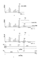
- FIG. 3 is a diagram illustrating an example of spectral characteristics of a color filter and an infrared light cut filter of a pixel used in the image sensor according to the embodiment of the present technology.
- “a” represents the relationship between the wavelength and the transmittance of the color filter arranged in the B pixel.
- B in the figure represents the relationship between the wavelength of the color filter arranged in the G pixel and the transmittance.
- C in the figure represents the relationship between the wavelength and transmittance of the color filter arranged in the R pixel.
- d represents the relationship between the wavelength and transmittance of the color filter arranged in the IR pixel.
- E in the figure represents the relationship between the wavelength and transmittance of the infrared light cut filter.
- the color filter of the IR pixel represented by d in FIG. 3 has a low transmittance in the visible light region and a high transmittance in the infrared light.
- a pixel using such a color filter is a pixel having low sensitivity to visible light and high sensitivity to infrared light, that is, an IR pixel.
- an infrared light cut filter having the spectral characteristics shown in e in FIG. 3 is used for the image sensor 300 having such pixels.
- the spectral characteristic of the infrared light cut filter has high transmittance for visible light and low transmittance for infrared light. Therefore, the R, G, and B pixels have little influence.
- the IR pixel the high transmittance in the infrared light region of the color filter in the pixel is offset and the transmittance becomes low.
- FIG. 4 is a diagram illustrating an example of pixel characteristics in the image sensor when the infrared light cut filter according to the embodiment of the present technology is used.
- a in the figure represents the relationship between the wavelength of the B pixel and the sensitivity.
- B in the figure represents the relationship between the wavelength of the G pixel and the sensitivity.
- C in the figure represents the relationship between the wavelength of the R pixel and the sensitivity.
- d represents the relationship between the wavelength and sensitivity of the IR pixel.
- the R, G, and B pixels have characteristics that have sensitivity to light of corresponding wavelengths without being affected by the infrared light cut filter.
- the sensitivity in the infrared light region becomes substantially zero by the infrared light cut filter.
- it has a low sensitivity for visible light.
- the IR pixel is a pixel corresponding to only visible light, and the sensitivity is low.
- the sensitivity of the low sensitivity pixel is assumed to be 1/10 of the sensitivity of the normal pixel.
- FIG. 5 is a diagram illustrating a configuration example of the imaging device according to the embodiment of the present technology.
- the imaging control apparatus 400 in the figure includes an image signal processing unit 401, a normal sensitivity histogram generation unit 402, and a low sensitivity histogram generation unit 403.
- the imaging control apparatus 400 includes a memory 404, a short exposure condition calculation unit 405, a synthesis unit 406, an exposure control unit 407, a short exposure control unit 408, an image output unit 409, and a control unit 410. Is further provided.
- the image signal processing unit 401 processes the image signal output from the image sensor 300. This process is, for example, a demosaic process. This is a process of generating image signals for other colors that the respective pixels do not have for the R, G, and B pixels.
- the memory 404 is a memory that stores image signals. The memory 404 holds an image signal obtained by the first photographing when generating an image with an expanded dynamic range by photographing twice.
- the synthesizing unit 406 synthesizes and outputs the image signal obtained by the first shooting held in the memory 404 and the image signal obtained by the second shooting output from the image signal processing unit 401. . Depending on the subject, there is a case where the dynamic range cannot be expanded even by two shootings.
- the synthesis unit 406 outputs the image signal held in the memory 404 without performing this synthesis process.
- the image output unit 409 outputs the image signal output from the combining unit 406 to the outside of the imaging apparatus 10.
- the image output unit 409 changes the format of the image signal as necessary and outputs it.
- the normal sensitivity histogram generation unit 402 generates a normal sensitivity histogram representing the appearance frequency distribution of the image signal based on the image signal.
- This normal sensitivity histogram is used for exposure control at the time of the first shooting in the imaging apparatus 10.
- the exposure control unit 407 controls exposure.
- the exposure control unit 407 controls exposure at the time of the first shooting in the imaging apparatus 10.
- This exposure control is to control the signal level of the image signal output by changing the exposure amount in the image sensor at the time of shooting to a predetermined value.
- the exposure amount can be controlled by changing the amount of incident light by the exposure time, which is the time from the start to the end of photoelectric conversion of the image sensor 300, or the stop.
- This exposure control can be performed by controlling the exposure time so that the evaluation value of the image signal, for example, the average value of the image signal becomes a predetermined signal level. This control method will be described later.
- the low sensitivity histogram generation unit 403 generates a low sensitivity histogram representing the appearance frequency distribution of the low sensitivity image signal based on the low sensitivity image signal. This low sensitivity histogram is used for calculating the exposure condition at the time of the second shooting in the imaging apparatus 10.
- the short-time exposure condition calculation unit 405 calculates an exposure condition for the second shooting in the imaging apparatus 10. The calculation of the exposure condition will be described later.
- the short-time exposure control unit 408 controls exposure.
- the short-time exposure control unit 408 controls exposure at the time of the second shooting in the imaging apparatus 10 based on the exposure condition calculated by the short-time exposure condition calculation unit 405.
- the control unit 410 selects a control signal output from the exposure control unit 407 or the short-time exposure control unit 408 and outputs the selected control signal to the image sensor 300.
- the control unit 410 also has a function of causing the short-time exposure control unit 408 to perform exposure control based on the normal sensitivity histogram generated by the normal sensitivity histogram generation unit 402. Further, the control unit 410 also performs overall control of the imaging control apparatus 400.
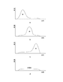
- FIG. 6 is a diagram for explaining the exposure control and the short-time exposure condition calculation method according to the embodiment of the present technology.
- a is an example of the normal sensitivity histogram generated by the normal sensitivity histogram generation unit 402
- the horizontal axis represents the signal level of the image signal output by the normal pixel
- the vertical axis represents the number of corresponding pixels.
- the image signal in the embodiment of the present technology is a 10-bit digital signal, and the signal level changes in the range of the value “0” to the value “1023”.
- the exposure control unit 407 calculates the average value of these image signals, and controls the exposure time so that this average value becomes equal to 20% of the maximum signal level.
- the exposure time is controlled so that the signal level becomes the value “200”.
- the image signal is saturated in the pixels included in the high luminance area. That is, so-called whiteout occurs.
- shooting with an expanded dynamic range is required.
- This determination is made as follows. The number of pixels whose signal level is saturated in the normal sensitivity histogram is calculated. In “a” in the figure, the number of pixels of the graph 501 having a signal level of 1023 is calculated. If this is greater than or equal to a predetermined saturation determination threshold, it is determined that shooting with an expanded dynamic range is necessary.
- the low-sensitivity histogram generation unit 403 generates a low-sensitivity histogram based on the low-sensitivity image signal by the low-sensitivity pixels existing around the pixel whose signal level is saturated.
- the graph 502 represents this low sensitivity histogram.
- the sensitivity of the low-sensitivity pixel is assumed to be 1/10 of that of the normal pixel, correction is performed by multiplying the low-sensitivity image signal by 10 that is the reciprocal of the sensitivity ratio.
- the signal level at which the number of pixels is maximized hereinafter referred to as the peak low-sensitivity pixel number signal level.
- the graph 503 represents a graph of the peak low-sensitivity pixel number signal level. Yes.
- the exposure condition for the second shooting is calculated by the short-time exposure condition calculation unit 405.
- the graph describing the normal sensitivity histogram and the low sensitivity histogram further shows the exposure range 504 for normal exposure in the first shooting and the exposure range 505 for short exposure in the second shooting.
- the average value of the signal level of the image signal that is, the average signal level of the normal histogram in the figure is controlled to be the value “200”.
- the average signal level is controlled to be a value “0”
- the image is blacked out
- the average signal level is controlled to be a value “1023”
- the image is in a whiteout state. It becomes.
- an area that is overexposed in normal exposure is an exposure range.
- the short-time exposure condition is calculated as follows based on the peak low-sensitivity pixel number signal level of the graph 503 described above.
- this signal level is a value “6000”
- an exposure condition is calculated such that the value is “200”, which is an average signal level in normal exposure.
- the exposure time is set to 1/30 of the exposure time for normal exposure.
- the exposure condition in the second shooting is estimated based on the low-sensitivity image signal, and shooting is performed.
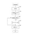
- FIG. 7 is a diagram illustrating an example of a processing procedure of imaging control processing according to the embodiment of the present technology.
- the imaging control apparatus 400 performs normal shooting, which is the first shooting (step S901). Specifically, exposure of the image sensor 300 is controlled by the exposure control unit 407, and photographing is performed. As a result, the image signal and the low-sensitivity image signal are output from the image sensor 300 to the imaging control device 400. The image signal is held in the memory 404.
- the imaging control apparatus 400 generates a normal sensitivity histogram from the image signal (step S902).
- the imaging control apparatus 400 determines whether or not the number of saturated pixels is equal to or greater than the saturation determination threshold value based on the normal sensitivity histogram (step S903). As a result, when it is less than the saturation determination threshold value (step S903: No), the process proceeds to S907. On the other hand, if it is equal to or greater than the saturation determination threshold (step S903: Yes), dynamic range expansion processing is performed (step S910). Thereafter, the obtained image signal is output (step S907). Note that when shooting is performed with the dynamic range expanded in the dynamic range expansion processing, an image signal obtained by synthesizing the image signal obtained by the shooting and the image signal obtained by the normal shooting is output. On the other hand, when shooting with an expanded dynamic range is not performed, an image signal obtained from normal shooting is output.
- FIG. 8 is a diagram illustrating an example of a processing procedure of dynamic range expansion processing according to the embodiment of the present technology.
- the imaging control apparatus 400 acquires a low-sensitivity image signal of low-sensitivity pixels around a saturated pixel (step S911).
- the imaging control apparatus 400 performs correction based on the sensitivity ratio (step S912). In the embodiment of the present technology, correction is performed by increasing the signal level of the low-sensitivity image signal by 10 times.
- the imaging control apparatus 400 generates a low sensitivity histogram (step S913).
- the imaging control apparatus 400 calculates the peak low-sensitivity pixel number signal level and the number of pixels corresponding thereto (Step S914).
- the dynamic range expansion process is terminated without performing shooting with the dynamic range expanded.
- step S915: Yes and step S916: Yes the imaging control device 400 calculates short-time exposure conditions (step S917).
- the imaging control apparatus 400 performs the second imaging under the short-time exposure condition (step S918).
- exposure of the image sensor 300 is controlled by the short-time exposure control unit 408, and photographing is performed.
- the imaging control apparatus 400 combines the image signal obtained by the second shooting and the image signal in the first shooting held in the memory 404 (step S919), and ends the dynamic range expansion process.
- an appropriate exposure condition is set based on the low-sensitivity image signal from the low-sensitivity pixel even in the second shooting. Can do.
- the processing procedure described in the above embodiment may be regarded as a method having a series of these procedures, and a program for causing a computer to execute these series of procedures or a recording medium storing the program. You may catch it.
- a recording medium for example, a CD (Compact Disc), an MD (MiniDisc), a DVD (Digital Versatile Disc), a memory card, a Blu-ray disc (Blu-ray (registered trademark) Disc), or the like can be used.
- this technique can also take the following structures.
- An image sensor that generates a normal pixel that generates an image signal and a low-sensitivity pixel that generates a low-sensitivity image signal and has a lower photoelectric conversion sensitivity to visible light than the normal pixel is controlled according to a predetermined exposure condition.
- An exposure control unit that causes the image sensor to output an image signal and the low-sensitivity image signal;
- a low sensitivity histogram generation unit that generates a low sensitivity histogram representing an appearance frequency distribution of the low sensitivity image signal based on the low sensitivity image signal;
- a short-time exposure condition calculation unit for calculating a short-time exposure condition having an exposure time shorter than the exposure condition based on the generated low sensitivity histogram;
- a short-time exposure control unit that controls the image sensor according to the calculated short-time exposure condition and outputs a short-time exposure image signal that is an image signal generated by the normal pixel to the image sensor;
- An imaging control apparatus comprising: a combining unit that combines the image signal and the short-exposure image signal.
- the imaging control apparatus further including a control unit that causes the short-time exposure control unit to perform the control based on the generated normal sensitivity histogram.
- an imaging device having a normal pixel that generates an image signal and a low-sensitivity pixel that generates a low-sensitivity image signal and has a lower photoelectric conversion sensitivity to visible light than the normal pixel;
- An imaging control device that controls the imaging element;
- the imaging control device includes: An exposure control unit that controls the image sensor according to a predetermined exposure condition to output the image signal and the low-sensitivity image signal to the image sensor;
- a low sensitivity histogram generation unit that generates a low sensitivity histogram representing an appearance frequency distribution of the low sensitivity image signal based on the low sensitivity image signal;
- a short-time exposure condition calculation unit for calculating a short-time exposure condition having an exposure time shorter than the exposure condition based on the generated low sensitivity histogram;
- a short-time exposure control unit that controls the image sensor according to the calculated short-time exposure condition and outputs a short-time exposure image signal that is an image signal generated by the normal pixel to the image sensor;
- An imaging apparatus comprising: a combining unit
- the normal pixel is a visible light pixel corresponding to visible light
- An image sensor that generates a normal pixel that generates an image signal and a low-sensitivity pixel that generates a low-sensitivity image signal and has a lower photoelectric conversion sensitivity to visible light than the normal pixel is controlled by a predetermined exposure condition.
- An exposure control procedure for causing the image sensor to output an image signal and the low-sensitivity image signal;
- a low sensitivity histogram generation procedure for generating a low sensitivity histogram representing an appearance frequency distribution of the low sensitivity image signal based on the low sensitivity image signal;
- a short-time exposure condition calculation procedure for calculating a short-time exposure condition having an exposure time shorter than the exposure condition based on the generated low sensitivity histogram;
- An imaging control method comprising: a synthesis procedure for synthesizing the image signal and the short-time exposure image signal.
- Imaging device 100 Lens 200 Infrared light cut filter 300 Imaging element 301 Pixel 400 Imaging control device 401 Image signal processing unit 402 Normal sensitivity histogram generation unit 403 Low sensitivity histogram generation unit 404 Memory 405 Short exposure condition calculation unit 406 Synthesis unit 407 Exposure control unit 408 Short-time exposure control unit 409 Image output unit 410 Control unit 501 to 503 Graph 504 Exposure range for normal exposure 505 Exposure range for short-time exposure
Landscapes
- Engineering & Computer Science (AREA)
- Multimedia (AREA)
- Signal Processing (AREA)
- Physics & Mathematics (AREA)
- General Physics & Mathematics (AREA)
- Studio Devices (AREA)
- Transforming Light Signals Into Electric Signals (AREA)
Abstract
Description
1.実施の形態の構成
2.実施の形態の動作
[撮像装置の構成]
図1は、本技術の実施の形態における撮像装置の構成例を示す図である。同図における撮像装置10は、レンズ100と、赤外光カットフィルタ200と、撮像素子300と、撮像制御装置400とを備える。
図2は、本技術の実施の形態における撮像素子の構成例を示す図である。同図は、撮像素子300の画素が配置された面である画素面の構成を表したものである。この画素面には画素301が2次元格子状に配置されている。この画素301に付されたR、G、BおよびIRは画素301の種類を表すものである。Rは赤色光に対応する画素(R画素)を表し、Gは緑色光に対応する画素(G画素)を表し、Bは青色光に対応する画素(B画素)を表し、IRは赤外光に対応する画素(IR画素)を表す。画素における光電変換素子は、可視光から赤外光に亘る広い範囲の波長の光に対し感度を有している。これを特定の波長の光にのみ対応する画素とするため、画素ごとに異なる分光特性を有するカラーフィルタを配置している。このカラーフィルタについては後述する。撮像素子300には、これら4種類の画素が画素面に規則的に配置されている。本技術の実施の形態においては、R画素、G画素およびB画素を通常画素とし、IR画素を低感度画素として使用する。
図3は、本技術の実施の形態における撮像素子に使用される画素のカラーフィルタおよび赤外光カットフィルタの分光特性の一例を示す図である。同図におけるaは、B画素に配置されたカラーフィルタの波長と透過率の関係を表したものである。同図におけるbは、G画素に配置されたカラーフィルタの波長と透過率の関係を表したものである。同図におけるcは、R画素に配置されたカラーフィルタの波長と透過率の関係を表したものである。同図におけるdは、IR画素に配置されたカラーフィルタの波長と透過率の関係を表したものである。同図におけるeは、赤外光カットフィルタの波長と透過率の関係を表したものである。このような各画素に対応する光に対する透過率が高いカラーフィルタを配置することにより、これらの画素を所望の特性としている。例えば、図3におけるdに表したIR画素のカラーフィルタは可視光領域における透過率が低く、赤外光における透過率が高い。
図4は、本技術の実施の形態における赤外光カットフィルタを使用した場合の撮像素子における画素の特性の一例を示す図である。同図におけるaは、B画素の波長と感度の関係を表したものである。同図におけるbは、G画素の波長と感度の関係を表したものである。同図におけるcは、R画素の波長と感度の関係を表したものである。同図におけるdは、IR画素の波長と感度の関係を表したものである。R、GおよびB画素においては、赤外光カットフィルタの影響を受けることなく、それぞれ対応する波長の光に対して感度を有する特性となっている。一方、IR画素においては、赤外光カットフィルタにより、赤外光領域の感度が略ゼロとなる。また、可視光に対しては、低い感度を有する特性となる。このように本技術の実施の形態では、赤外光カットフィルタを使用することにより、IR画素を可視光にのみ対応する画素とするとともに、感度が低い低感度画素としている。なお、本技術の実施の形態においては、この低感度画素の感度を通常画素の感度の10分の1と想定する。
図5は、本技術の実施の形態における撮像装置の構成例を示す図である。同図における撮像制御装置400は、画像信号処理部401と、通常感度ヒストグラム生成部402と、低感度ヒストグラム生成部403とを備える。また、撮像制御装置400は、メモリ404と、短時間露光条件算出部405と、合成部406と、露光制御部407と、短時間露光制御部408と、画像出力部409と、制御部410とをさらに備える。
図6は、本技術の実施の形態における露光制御と短時間露光条件の算出方法を説明する図である。同図におけるaは、通常感度ヒストグラム生成部402により生成された通常感度ヒストグラムの一例であり、横軸は通常画素が出力した画像信号の信号レベルを表し、縦軸は対応する画素の個数を表している。なお、本技術の実施の形態における画像信号は10ビットデジタル信号であり、信号レベルは値「0」から値「1023」の範囲で変化する。露光制御部407は、これら画像信号の平均値を算出し、この平均値が最大信号レベルの20%の値に等しくなるように露光時間を制御する。同図におけるaでは、信号レベルが値「200」となるように露光時間を制御する。被写体が高輝度の領域を含む場合、この高輝度の領域に含まれる画素は画像信号が飽和する。つまり、いわゆる白飛びが発生する。このような場合、ダイナミックレンジを拡大した撮影が必要となる。この判断は、次のように行う。通常感度ヒストグラムにおいて信号レベルが飽和状態にある画素の画素数を算出する。同図におけるaでは、信号レベルが1023であるグラフ501の画素数を算出する。これが所定の飽和判定閾値以上である場合には、ダイナミックレンジを拡大した撮影が必要と判断する。この場合、信号レベルが飽和状態にある画素の周囲に存在する低感度画素による低感度画像信号に基づいて、低感度ヒストグラム生成部403が低感度ヒストグラムを生成する。
次に、2度の撮影によりダイナミックレンジを拡大した画像を生成する撮像装置における動作について説明する。
図7は、本技術の実施の形態における撮像制御処理の処理手順の一例を示す図である。まず、撮像制御装置400は、1回目の撮影である通常撮影を行う(ステップS901)。具体的には、露光制御部407により撮像素子300の露光が制御され、撮影が行われる。これにより、画像信号と低感度画像信号が、撮像素子300から撮像制御装置400に出力される。また、画像信号はメモリ404に保持される。次に、撮像制御装置400は、画像信号から通常感度ヒストグラムを生成する(ステップS902)。次に、撮像制御装置400は、通常感度ヒストグラムに基づいて、飽和画素数が飽和判定閾値以上であるか否かを判断する(ステップS903)。その結果、飽和判定閾値未満である場合は(ステップS903:No)、S907の処理に移行する。一方、飽和判定閾値以上である場合は(ステップS903:Yes)、ダイナミックレンジ拡大処理を行う(ステップS910)。その後、得られた画像信号を出力する(ステップS907)。なお、ダイナミックレンジ拡大処理においてダイナミックレンジを拡大した撮影を行った場合には、この撮影により得られた画像信号と通常撮影により得られた画像信号とを合成した画像信号を出力する。一方、ダイナミックレンジを拡大した撮影を行わなかった場合には、通常撮影より得られた画像信号を出力する。
図8は、本技術の実施の形態におけるダイナミックレンジ拡大処理の処理手順の一例を示す図である。まず、撮像制御装置400は、飽和した画素の周囲の低感度画素の低感度画像信号を取得する(ステップS911)。次に、撮像制御装置400は、感度比に基づく補正を行う(ステップS912)。本技術の実施の形態においては、低感度画像信号の信号レベルを10倍にすることにより、補正を行う。次に、撮像制御装置400は、低感度ヒストグラムを生成する(ステップS913)。次に、撮像制御装置400は、ピーク低感度画素数信号レベルおよびこれに該当する画素数を算出する(ステップS914)。この画素数が飽和判定閾値以上または不飽和判定閾値未満である場合は(ステップS915:NoまたはステップS916:No)、ダイナミックレンジを拡大した撮影を行わずにダイナミックレンジ拡大処理を終了する。
(1)画像信号を生成する通常画素と低感度画像信号を生成して前記通常画素よりも可視光に対する光電変換感度が低い低感度画素とを有する撮像素子を所定の露光条件により制御して前記画像信号および前記低感度画像信号を前記撮像素子に出力させる露光制御部と、
前記低感度画像信号に基づいて前記低感度画像信号の出現頻度分布を表す低感度ヒストグラムを生成する低感度ヒストグラム生成部と、
前記生成された前記低感度ヒストグラムに基づいて前記露光条件より露光時間が短い短時間露光条件を算出する短時間露光条件算出部と、
前記撮像素子を前記算出された前記短時間露光条件により制御して前記通常画素が生成する画像信号である短時間露光画像信号を前記撮像素子に出力させる短時間露光制御部と、
前記画像信号および前記短時間露光画像信号を合成する合成部と
を具備する撮像制御装置。
(2)前記画像信号に基づいて前記画像信号の出現頻度分布を表す通常感度ヒストグラムを生成する通常感度ヒストグラム生成部と、
前記生成された前記通常感度ヒストグラムに基づいて前記短時間露光制御部に前記制御を行わせる制御部と
をさらに具備する前記(1)に記載の撮像制御装置。
(3)画像信号を生成する通常画素と低感度画像信号を生成して前記通常画素よりも可視光に対する光電変換感度が低い低感度画素とを有する撮像素子と、
前記撮像素子を制御する撮像制御装置と
を具備し、
前記撮像制御装置は、
前記撮像素子を所定の露光条件により制御して前記画像信号および前記低感度画像信号を前記撮像素子に出力させる露光制御部と、
前記低感度画像信号に基づいて前記低感度画像信号の出現頻度分布を表す低感度ヒストグラムを生成する低感度ヒストグラム生成部と、
前記生成された前記低感度ヒストグラムに基づいて前記露光条件より露光時間が短い短時間露光条件を算出する短時間露光条件算出部と、
前記撮像素子を前記算出された前記短時間露光条件により制御して前記通常画素が生成する画像信号である短時間露光画像信号を前記撮像素子に出力させる短時間露光制御部と、
前記画像信号および前記短時間露光画像信号を合成する合成部と
を備える
撮像装置。
(4)赤外光を遮断する赤外光カットフィルタをさらに具備し、
前記通常画素は、可視光に対応する可視光画素であり、
前記低感度画素は、赤外光に対応する赤外光画素である
前記(3)に記載の撮像装置。
(5)画像信号を生成する通常画素と低感度画像信号を生成して前記通常画素よりも可視光に対する光電変換感度が低い低感度画素とを有する撮像素子を所定の露光条件により制御して前記画像信号および前記低感度画像信号を前記撮像素子に出力させる露光制御手順と、
前記低感度画像信号に基づいて前記低感度画像信号の出現頻度分布を表す低感度ヒストグラムを生成する低感度ヒストグラム生成手順と、
前記生成された前記低感度ヒストグラムに基づいて前記露光条件より露光時間が短い短時間露光条件を算出する短時間露光条件算出手順と、
前記撮像素子を前記算出された前記短時間露光条件により制御して前記通常画素が生成する画像信号である短時間露光画像信号を前記撮像素子に出力させる短時間露光制御手順と、
前記画像信号および前記短時間露光画像信号を合成する合成手順と
を具備する撮像制御方法。
100 レンズ
200 赤外光カットフィルタ
300 撮像素子
301 画素
400 撮像制御装置
401 画像信号処理部
402 通常感度ヒストグラム生成部
403 低感度ヒストグラム生成部
404 メモリ
405 短時間露光条件算出部
406 合成部
407 露光制御部
408 短時間露光制御部
409 画像出力部
410 制御部
501~503 グラフ
504 通常露光の露光範囲
505 短時間露光の露光範囲
Claims (5)
- 画像信号を生成する通常画素と低感度画像信号を生成して前記通常画素よりも可視光に対する光電変換感度が低い低感度画素とを有する撮像素子を所定の露光条件により制御して前記画像信号および前記低感度画像信号を前記撮像素子に出力させる露光制御部と、
前記低感度画像信号に基づいて前記低感度画像信号の出現頻度分布を表す低感度ヒストグラムを生成する低感度ヒストグラム生成部と、
前記生成された前記低感度ヒストグラムに基づいて前記露光条件より露光時間が短い短時間露光条件を算出する短時間露光条件算出部と、
前記撮像素子を前記算出された前記短時間露光条件により制御して前記通常画素が生成する画像信号である短時間露光画像信号を前記撮像素子に出力させる短時間露光制御部と、
前記画像信号および前記短時間露光画像信号を合成する合成部と
を具備する撮像制御装置。 - 前記画像信号に基づいて前記画像信号の出現頻度分布を表す通常感度ヒストグラムを生成する通常感度ヒストグラム生成部と、
前記生成された前記通常感度ヒストグラムに基づいて前記短時間露光制御部に前記制御を行わせる制御部と
をさらに具備する請求項1記載の撮像制御装置。 - 画像信号を生成する通常画素と低感度画像信号を生成して前記通常画素よりも可視光に対する光電変換感度が低い低感度画素とを有する撮像素子と、
前記撮像素子を制御する撮像制御装置と
を具備し、
前記撮像制御装置は、
前記撮像素子を所定の露光条件により制御して前記画像信号および前記低感度画像信号を前記撮像素子に出力させる露光制御部と、
前記低感度画像信号に基づいて前記低感度画像信号の出現頻度分布を表す低感度ヒストグラムを生成する低感度ヒストグラム生成部と、
前記生成された前記低感度ヒストグラムに基づいて前記露光条件より露光時間が短い短時間露光条件を算出する短時間露光条件算出部と、
前記撮像素子を前記算出された前記短時間露光条件により制御して前記通常画素が生成する画像信号である短時間露光画像信号を前記撮像素子に出力させる短時間露光制御部と、
前記画像信号および前記短時間露光画像信号を合成する合成部と
を備える
撮像装置。 - 赤外光を遮断する赤外光カットフィルタをさらに具備し、
前記通常画素は、可視光に対応する可視光画素であり、
前記低感度画素は、赤外光に対応する赤外光画素である
請求項3記載の撮像装置。 - 画像信号を生成する通常画素と低感度画像信号を生成して前記通常画素よりも可視光に対する光電変換感度が低い低感度画素とを有する撮像素子を所定の露光条件により制御して前記画像信号および前記低感度画像信号を前記撮像素子に出力させる露光制御手順と、
前記低感度画像信号に基づいて前記低感度画像信号の出現頻度分布を表す低感度ヒストグラムを生成する低感度ヒストグラム生成手順と、
前記生成された前記低感度ヒストグラムに基づいて前記露光条件より露光時間が短い短時間露光条件を算出する短時間露光条件算出手順と、
前記撮像素子を前記算出された前記短時間露光条件により制御して前記通常画素が生成する画像信号である短時間露光画像信号を前記撮像素子に出力させる短時間露光制御手順と、
前記画像信号および前記短時間露光画像信号を合成する合成手順と
を具備する撮像制御方法。
Priority Applications (3)
| Application Number | Priority Date | Filing Date | Title |
|---|---|---|---|
| CN201580038563.2A CN106537896B (zh) | 2014-07-18 | 2015-05-29 | 成像控制器件、成像装置和成像控制方法 |
| US15/323,208 US9894284B2 (en) | 2014-07-18 | 2015-05-29 | Imaging control device, imaging apparatus, and imaging control method |
| JP2016534315A JP6564368B2 (ja) | 2014-07-18 | 2015-05-29 | 撮像制御装置、撮像装置および撮像制御方法 |
Applications Claiming Priority (2)
| Application Number | Priority Date | Filing Date | Title |
|---|---|---|---|
| JP2014-147583 | 2014-07-18 | ||
| JP2014147583 | 2014-07-18 |
Publications (1)
| Publication Number | Publication Date |
|---|---|
| WO2016009729A1 true WO2016009729A1 (ja) | 2016-01-21 |
Family
ID=55078232
Family Applications (1)
| Application Number | Title | Priority Date | Filing Date |
|---|---|---|---|
| PCT/JP2015/065576 Ceased WO2016009729A1 (ja) | 2014-07-18 | 2015-05-29 | 撮像制御装置、撮像装置および撮像制御方法 |
Country Status (4)
| Country | Link |
|---|---|
| US (1) | US9894284B2 (ja) |
| JP (1) | JP6564368B2 (ja) |
| CN (1) | CN106537896B (ja) |
| WO (1) | WO2016009729A1 (ja) |
Families Citing this family (2)
| Publication number | Priority date | Publication date | Assignee | Title |
|---|---|---|---|---|
| US10965894B2 (en) * | 2017-11-20 | 2021-03-30 | Flir Commercial Systems, Inc. | Short wave infrared image sensor with automatic exposure and dynamic range control |
| KR20240116480A (ko) * | 2021-12-06 | 2024-07-29 | 소니 세미컨덕터 솔루션즈 가부시키가이샤 | 센서 노출 모드 컨트롤 및 센서 노출 모드 제어 방법 |
Citations (3)
| Publication number | Priority date | Publication date | Assignee | Title |
|---|---|---|---|---|
| JP2005072965A (ja) * | 2003-08-25 | 2005-03-17 | Fuji Photo Film Co Ltd | 画像合成方法及び固体撮像装置並びにデジタルカメラ |
| JP2008270832A (ja) * | 2008-06-10 | 2008-11-06 | Fujifilm Corp | 固体撮像素子及び撮像装置 |
| JP2012205030A (ja) * | 2011-03-25 | 2012-10-22 | Hitachi Consumer Electronics Co Ltd | 画像信号処理装置 |
Family Cites Families (9)
| Publication number | Priority date | Publication date | Assignee | Title |
|---|---|---|---|---|
| JP3639627B2 (ja) | 1995-02-03 | 2005-04-20 | キヤノン株式会社 | 画像合成装置 |
| JP2005051695A (ja) * | 2003-07-31 | 2005-02-24 | Fuji Photo Film Co Ltd | 画像合成方法及び固体撮像装置並びにデジタルカメラ |
| US8446480B2 (en) * | 2006-12-20 | 2013-05-21 | Nokia Corporation | Exposure control based on image sensor cost function |
| US7825966B2 (en) * | 2007-06-29 | 2010-11-02 | Omnivision Technologies, Inc. | High dynamic range sensor with blooming drain |
| CN101394487B (zh) * | 2008-10-27 | 2011-09-14 | 华为技术有限公司 | 一种合成图像的方法与系统 |
| CN102158653B (zh) * | 2011-05-03 | 2013-01-16 | 东华大学 | 一种实时高动态范围数字图像获取装置及方法 |
| JP2013021660A (ja) * | 2011-07-14 | 2013-01-31 | Sony Corp | 画像処理装置、撮像装置、および画像処理方法、並びにプログラム |
| EP2709350B1 (en) * | 2012-09-14 | 2015-06-03 | Axis AB | Configuration of image capturing settings |
| EP2946249B1 (en) * | 2013-01-15 | 2018-05-23 | Avigilon Corporation | Imaging apparatus with scene adaptive auto exposure compensation |
-
2015
- 2015-05-29 CN CN201580038563.2A patent/CN106537896B/zh active Active
- 2015-05-29 WO PCT/JP2015/065576 patent/WO2016009729A1/ja not_active Ceased
- 2015-05-29 US US15/323,208 patent/US9894284B2/en not_active Expired - Fee Related
- 2015-05-29 JP JP2016534315A patent/JP6564368B2/ja not_active Expired - Fee Related
Patent Citations (3)
| Publication number | Priority date | Publication date | Assignee | Title |
|---|---|---|---|---|
| JP2005072965A (ja) * | 2003-08-25 | 2005-03-17 | Fuji Photo Film Co Ltd | 画像合成方法及び固体撮像装置並びにデジタルカメラ |
| JP2008270832A (ja) * | 2008-06-10 | 2008-11-06 | Fujifilm Corp | 固体撮像素子及び撮像装置 |
| JP2012205030A (ja) * | 2011-03-25 | 2012-10-22 | Hitachi Consumer Electronics Co Ltd | 画像信号処理装置 |
Also Published As
| Publication number | Publication date |
|---|---|
| JP6564368B2 (ja) | 2019-08-21 |
| JPWO2016009729A1 (ja) | 2017-04-27 |
| CN106537896A (zh) | 2017-03-22 |
| CN106537896B (zh) | 2019-10-22 |
| US20170142311A1 (en) | 2017-05-18 |
| US9894284B2 (en) | 2018-02-13 |
Similar Documents
| Publication | Publication Date | Title |
|---|---|---|
| JP4479457B2 (ja) | 画像処理装置、および画像処理方法、並びにコンピュータ・プログラム | |
| WO2016056279A1 (ja) | 画像処理装置、撮像装置および撮像方法 | |
| JP6460653B2 (ja) | 画像処理装置、それを備えた撮像装置、画像処理方法、及び画像処理プログラム | |
| WO2016047240A1 (ja) | 画像処理装置、撮像素子、撮像装置および画像処理方法 | |
| WO2019146226A1 (ja) | 画像処理装置、および出力情報制御方法、並びにプログラム | |
| WO2016111072A1 (ja) | 画像処理装置、撮像装置および画像処理方法 | |
| JP2011091570A (ja) | 撮像装置 | |
| US20170230571A1 (en) | Image processing apparatus, image-pickup apparatus, image processing method, non-transitory computer-readable storage medium | |
| WO2017149854A1 (ja) | 信号処理装置、撮像装置および信号処理方法 | |
| JP2007174277A (ja) | 画像信号処理装置、撮像装置、および画像信号処理方法、並びにコンピュータ・プログラム | |
| JPWO2016143134A1 (ja) | 画像処理装置、画像処理方法およびプログラム | |
| WO2016117137A1 (ja) | 撮像装置、撮像方法、および画像表示装置 | |
| US20180197282A1 (en) | Method and device for producing a digital image | |
| JP5826901B2 (ja) | 撮像装置及び光軸位置算出方法 | |
| JP5047055B2 (ja) | 画像処理装置、撮像装置及び画像処理方法 | |
| JP5159715B2 (ja) | 画像処理装置 | |
| JP6564368B2 (ja) | 撮像制御装置、撮像装置および撮像制御方法 | |
| JP2013171257A (ja) | 撮像装置およびその制御方法 | |
| JP6742231B2 (ja) | 画像処理装置及び方法、及び撮像装置 | |
| JP5419749B2 (ja) | 画像処理装置、画像処理方法およびプログラム | |
| JP6091311B2 (ja) | 撮像装置 | |
| JP2015179968A (ja) | 装置、方法、及びプログラム | |
| JP6536000B2 (ja) | 撮影装置 | |
| JP2016082390A (ja) | 信号処理装置 | |
| US10341556B2 (en) | Image capturing apparatus and control method therefor |
Legal Events
| Date | Code | Title | Description |
|---|---|---|---|
| 121 | Ep: the epo has been informed by wipo that ep was designated in this application |
Ref document number: 15821819 Country of ref document: EP Kind code of ref document: A1 |
|
| ENP | Entry into the national phase |
Ref document number: 2016534315 Country of ref document: JP Kind code of ref document: A |
|
| WWE | Wipo information: entry into national phase |
Ref document number: 15323208 Country of ref document: US |
|
| NENP | Non-entry into the national phase |
Ref country code: DE |
|
| 122 | Ep: pct application non-entry in european phase |
Ref document number: 15821819 Country of ref document: EP Kind code of ref document: A1 |