WO2016009678A1 - Dispositif d'alimentation en liquide et dispositif d'enregistrement d'image - Google Patents
Dispositif d'alimentation en liquide et dispositif d'enregistrement d'image Download PDFInfo
- Publication number
- WO2016009678A1 WO2016009678A1 PCT/JP2015/058327 JP2015058327W WO2016009678A1 WO 2016009678 A1 WO2016009678 A1 WO 2016009678A1 JP 2015058327 W JP2015058327 W JP 2015058327W WO 2016009678 A1 WO2016009678 A1 WO 2016009678A1
- Authority
- WO
- WIPO (PCT)
- Prior art keywords
- liquid
- storage tank
- supply
- time
- liquid feeding
- Prior art date
Links
Images


Classifications
-
- A—HUMAN NECESSITIES
- A61—MEDICAL OR VETERINARY SCIENCE; HYGIENE
- A61B—DIAGNOSIS; SURGERY; IDENTIFICATION
- A61B1/00—Instruments for performing medical examinations of the interior of cavities or tubes of the body by visual or photographical inspection, e.g. endoscopes; Illuminating arrangements therefor
- A61B1/12—Instruments for performing medical examinations of the interior of cavities or tubes of the body by visual or photographical inspection, e.g. endoscopes; Illuminating arrangements therefor with cooling or rinsing arrangements
- A61B1/121—Instruments for performing medical examinations of the interior of cavities or tubes of the body by visual or photographical inspection, e.g. endoscopes; Illuminating arrangements therefor with cooling or rinsing arrangements provided with means for cleaning post-use
- A61B1/123—Instruments for performing medical examinations of the interior of cavities or tubes of the body by visual or photographical inspection, e.g. endoscopes; Illuminating arrangements therefor with cooling or rinsing arrangements provided with means for cleaning post-use using washing machines
-
- A—HUMAN NECESSITIES
- A61—MEDICAL OR VETERINARY SCIENCE; HYGIENE
- A61B—DIAGNOSIS; SURGERY; IDENTIFICATION
- A61B1/00—Instruments for performing medical examinations of the interior of cavities or tubes of the body by visual or photographical inspection, e.g. endoscopes; Illuminating arrangements therefor
- A61B1/12—Instruments for performing medical examinations of the interior of cavities or tubes of the body by visual or photographical inspection, e.g. endoscopes; Illuminating arrangements therefor with cooling or rinsing arrangements
-
- A—HUMAN NECESSITIES
- A61—MEDICAL OR VETERINARY SCIENCE; HYGIENE
- A61L—METHODS OR APPARATUS FOR STERILISING MATERIALS OR OBJECTS IN GENERAL; DISINFECTION, STERILISATION OR DEODORISATION OF AIR; CHEMICAL ASPECTS OF BANDAGES, DRESSINGS, ABSORBENT PADS OR SURGICAL ARTICLES; MATERIALS FOR BANDAGES, DRESSINGS, ABSORBENT PADS OR SURGICAL ARTICLES
- A61L2/00—Methods or apparatus for disinfecting or sterilising materials or objects other than foodstuffs or contact lenses; Accessories therefor
- A61L2/16—Methods or apparatus for disinfecting or sterilising materials or objects other than foodstuffs or contact lenses; Accessories therefor using chemical substances
- A61L2/18—Liquid substances or solutions comprising solids or dissolved gases
-
- B—PERFORMING OPERATIONS; TRANSPORTING
- B08—CLEANING
- B08B—CLEANING IN GENERAL; PREVENTION OF FOULING IN GENERAL
- B08B3/00—Cleaning by methods involving the use or presence of liquid or steam
- B08B3/04—Cleaning involving contact with liquid
-
- B—PERFORMING OPERATIONS; TRANSPORTING
- B08—CLEANING
- B08B—CLEANING IN GENERAL; PREVENTION OF FOULING IN GENERAL
- B08B3/00—Cleaning by methods involving the use or presence of liquid or steam
- B08B3/04—Cleaning involving contact with liquid
- B08B3/08—Cleaning involving contact with liquid the liquid having chemical or dissolving effect
-
- B—PERFORMING OPERATIONS; TRANSPORTING
- B67—OPENING, CLOSING OR CLEANING BOTTLES, JARS OR SIMILAR CONTAINERS; LIQUID HANDLING
- B67D—DISPENSING, DELIVERING OR TRANSFERRING LIQUIDS, NOT OTHERWISE PROVIDED FOR
- B67D7/00—Apparatus or devices for transferring liquids from bulk storage containers or reservoirs into vehicles or into portable containers, e.g. for retail sale purposes
- B67D7/06—Details or accessories
- B67D7/58—Arrangements of pumps
- B67D7/62—Arrangements of pumps power operated
-
- B—PERFORMING OPERATIONS; TRANSPORTING
- B67—OPENING, CLOSING OR CLEANING BOTTLES, JARS OR SIMILAR CONTAINERS; LIQUID HANDLING
- B67D—DISPENSING, DELIVERING OR TRANSFERRING LIQUIDS, NOT OTHERWISE PROVIDED FOR
- B67D7/00—Apparatus or devices for transferring liquids from bulk storage containers or reservoirs into vehicles or into portable containers, e.g. for retail sale purposes
- B67D7/06—Details or accessories
- B67D7/76—Arrangements of devices for purifying liquids to be transferred, e.g. of filters, of air or water separators
- B67D7/763—Arrangements of devices for purifying liquids to be transferred, e.g. of filters, of air or water separators of air separators
-
- G—PHYSICS
- G05—CONTROLLING; REGULATING
- G05D—SYSTEMS FOR CONTROLLING OR REGULATING NON-ELECTRIC VARIABLES
- G05D7/00—Control of flow
- G05D7/06—Control of flow characterised by the use of electric means
- G05D7/0617—Control of flow characterised by the use of electric means specially adapted for fluid materials
- G05D7/0629—Control of flow characterised by the use of electric means specially adapted for fluid materials characterised by the type of regulator means
- G05D7/0676—Control of flow characterised by the use of electric means specially adapted for fluid materials characterised by the type of regulator means by action on flow sources
-
- A—HUMAN NECESSITIES
- A61—MEDICAL OR VETERINARY SCIENCE; HYGIENE
- A61L—METHODS OR APPARATUS FOR STERILISING MATERIALS OR OBJECTS IN GENERAL; DISINFECTION, STERILISATION OR DEODORISATION OF AIR; CHEMICAL ASPECTS OF BANDAGES, DRESSINGS, ABSORBENT PADS OR SURGICAL ARTICLES; MATERIALS FOR BANDAGES, DRESSINGS, ABSORBENT PADS OR SURGICAL ARTICLES
- A61L2202/00—Aspects relating to methods or apparatus for disinfecting or sterilising materials or objects
- A61L2202/20—Targets to be treated
- A61L2202/24—Medical instruments, e.g. endoscopes, catheters, sharps
-
- B—PERFORMING OPERATIONS; TRANSPORTING
- B01—PHYSICAL OR CHEMICAL PROCESSES OR APPARATUS IN GENERAL
- B01J—CHEMICAL OR PHYSICAL PROCESSES, e.g. CATALYSIS OR COLLOID CHEMISTRY; THEIR RELEVANT APPARATUS
- B01J4/00—Feed or outlet devices; Feed or outlet control devices
Definitions
- the present invention relates to a liquid supply apparatus and an endoscope reprocessing apparatus provided with a liquid supply pipe for discharging a liquid in a storage tank.
- Endoscopes used in the medical field are subjected to processing using fluids such as cleaning and disinfection after use.
- an apparatus that automatically performs a cleaning process, a disinfection process, and the like on an endoscope an endoscope reprocessing apparatus as disclosed in, for example, Japanese Patent Application Laid-Open No. 2010-57752 is known.
- the endoscope reprocessing apparatus includes a liquid supply apparatus that stores liquids such as a cleaning liquid and a disinfecting liquid and discharges a predetermined amount of liquid as the processing process proceeds.
- a liquid supply apparatus includes a storage tank that stores liquid, a first end that opens in the storage tank, and a second end that stores the storage tank. And a liquid supply section such as a pump provided in the supply pipe.
- the liquid in the supply pipe returns to the storage tank, so that air enters the supply pipe. If air is present in the supply pipe line, it causes a variation in the volume of the liquid discharged from the liquid supply device. Therefore, in the conventional liquid supply apparatus, prior to the discharge of the liquid, an air venting process is performed in which the liquid feeding unit is operated for a predetermined time and air that has entered the supply pipe is extracted.
- the liquid stored in the liquid supply device is consumed. Moreover, time is also required for performing the air venting process.
- This invention solves the above-mentioned point, and it aims at providing the liquid supply apparatus and endoscope reprocessing apparatus which suppressed the liquid consumed in the air venting process, and time.
- a liquid supply apparatus includes a storage tank for storing a liquid, a first end connected to the storage tank, extending from the storage tank, and the liquid remaining inside the storage tank over time.
- a liquid supply section that is disposed in a fixed amount, a supply pipe that flows back to the storage tank, the storage tank, or the supply pipe, and that sends the liquid from the storage tank to a second end of the supply pipe;
- a time measuring unit that measures an elapsed time from the stop of the liquid feeding by the liquid feeding unit, and is connected to the liquid feeding unit and the time measuring unit, and drives the liquid feeding unit for a predetermined time based on the length of the elapsed time.
- a control unit that measures an elapsed time from the stop of the liquid feeding by the liquid feeding unit, and is connected to the liquid feeding unit and the time measuring unit, and drives the liquid feeding unit for a predetermined time based on the length of the elapsed time.
- An endoscope reprocessing apparatus includes the liquid supply device, a treatment tank in which the endoscope can be disposed, and the liquid supplied from the liquid supply device is introduced; including.
- a liquid supply apparatus 1 of the present embodiment shown in FIG. 1 includes a storage tank 2 that stores liquid F, a supply line 3 having a first end 3 a connected to the storage tank 2, and the storage tank 2.
- the liquid supply apparatus 1 includes a liquid flow detection unit 5, a time measuring unit 6, and a control unit 7.
- the liquid supply apparatus 1 is an apparatus that discharges the liquid F in the storage tank 2 from the second end 3 b of the supply pipe 3 by operating the liquid feeding section 4.
- the liquid supply apparatus 1 is incorporated in an apparatus that handles the liquid F.
- the liquid supply apparatus 1 is provided in an endoscope reprocessing apparatus 20 that handles the liquid F, as shown in FIG.
- the directions of up and down are used, which is in a state where the liquid supply device 1 and the endoscope reprocessing device 20 are arranged in a usable posture. It is above and below the direction of gravity. Above the direction of gravity is a direction away from the gravity source, and below the direction of gravity is a direction approaching the gravity source.
- the liquid supply apparatus 1 includes a power supply unit for supplying power to each part that requires power.
- the power supply unit may be configured to obtain power from the outside such as a commercial power supply, or may be configured to include a power generation device and a battery to obtain power from these.
- the control unit 7 includes an arithmetic device (CPU), a storage device (RAM), an auxiliary storage device, an input / output device, a power control device, and the like, and operates each part constituting the liquid supply device 1.
- the control is based on a predetermined program.
- the control unit 7 includes a time measuring unit 6 that recognizes an elapsed time from a predetermined time.
- the timer 6 may be a timer that counts the elapsed time from the predetermined time, or recognizes the elapsed time from the predetermined time by comparing the stored predetermined time (date and time) with the current time. Form may be sufficient.
- the timekeeping unit 6 may have a configuration independent of the control unit 7.
- the control unit 7 may have a configuration for controlling the operation of each part of the endoscope reprocessing device 20 based on a predetermined program in addition to the liquid supply device 1.
- the power supply unit may have a configuration for supplying power to each part of the endoscope reprocessing device 20.
- the storage tank 2 is a part for storing the liquid F.
- the storage tank 2 has a container-like form with the top closed in the illustrated embodiment, but the storage tank 2 may be a member having a space for holding the liquid F therein.
- the storage tank 2 may have a bowl-like shape whose upper part is open to the atmosphere.
- the storage tank 2 may be in a removable form.
- the storage tank 2 is not limited to a form made of a member having a predetermined rigidity, and may be a bag-like form made of a soft member.
- the supply pipeline 3 is a pipeline that is connected to the storage tank 2 at the first end 3 a and extends outside the storage tank 2.
- the first end 3 a of the supply pipe 3 is opened inside the storage tank 2, and the second end 3 b is opened outside the storage tank 2.
- the second end 3b of the supply pipeline 3 is connected to a processing tank 22 provided in an endoscope reprocessing device 20 described later.
- the first end 3 a of the supply pipe 3 is open at the bottom surface of the storage tank 2.
- the first end 3a of the supply pipe 3 is not limited to a form opening at the bottom surface of the storage tank 2 as shown in the figure, and is disposed at a predetermined distance from the lowest point on the bottom surface of the storage tank 2. It may be. Further, the first end 3 a of the supply pipeline 3 may be open on the side surface of the storage tank 2. Further, the first end portion 3 a of the supply pipe line 3 may be opened at a plurality of locations in the storage tank 2.
- the other end (second end) 3 b of the supply pipe 3 is disposed above the maximum liquid level of the storage tank 2.
- the maximum liquid level is the highest level at which the liquid level of the liquid F can reach in the storage tank 2, for example, the full water level of the storage tank 2 or the arrangement water level of the water level sensor provided in the storage tank. Can be mentioned. Since the second end 3b of the supply pipe 3 is located above the maximum liquid level of the storage tank 2, the liquid F in the storage tank 2 is siphoned while the liquid feeding section 4 is stopped. In principle, it does not flow out of the second end 3b through the conduit 3. In the illustrated embodiment, the second end 3b of the supply pipe 3 opens downward, but the direction of the opening of the second end 3b is not particularly limited.
- the second end portion 3b of the supply pipe line 3 is located above the maximum liquid level height of the storage tank 2, it remains inside the supply pipe line 3 while the liquid feeding part 4 is stopped.
- the liquid F that has been returned returns to the storage tank 2 by a predetermined amount over time.
- the flow of the liquid F in the supply pipe 3 while the liquid feeding section 4 is stopped is opposite to the direction in which the liquid F flows in the supply pipe 3 by the operation of the liquid feeding section 4. Can be called.
- the supply pipeline 3 of the present embodiment includes two sections, a first pipeline 3c on the first end portion 3a side and a second pipeline 3d on the second end portion 3b side.
- the first pipe line 3 c is a section having a first connection part 3 e connected to the storage tank 2 and being lower than the storage tank 2.
- the 2nd pipe line 3d is the area between the 1st pipe line 3c arrange
- the supply pipe 3 is provided with a liquid feeding section 4 and a liquid flow detecting section 5 which will be described later.
- the supply pipeline 3 may be branched on the second end 3 b side from the liquid feeding unit 4. That is, the second end 3b of the supply pipeline 3 may be plural.
- the liquid feeding unit 4 is a pump that transfers the fluid in the supply pipeline 3 from the first end 3a toward the second end 3b.
- the liquid feeding unit 4 is disposed in the first pipeline 3c.
- the liquid feeding unit 4 is electrically connected to the control unit 7, and the operation of the liquid feeding unit 4 is controlled by the control unit 7.
- the liquid feeding unit 4 does not have a configuration such as a check valve that completely stops the flow of the fluid in the supply pipeline 3 from the second end 3b side to the first end 3a side. That is, when the liquid feeding part 4 is stopped, the liquid feeding part 4 acts as a constriction part for narrowing the cross-sectional area of the supply pipe line 3, and the flow resistance of the fluid in the supply pipe line 3 is reduced. Cause, but do not block flow. Such pumps are common.
- the configuration can be simplified by adopting a configuration in which the liquid feeding section 4 does not prevent backflow when stopped.
- the liquid feeding section 4 may be provided with a loose check valve that does not completely block the flow of the fluid in the supply pipe 3 from the second end 3b side to the first end 3a side. Good.
- the liquid F since the first pipeline 3c is located below the storage tank 2, the liquid F always exists in the first pipeline 3c. That is, the liquid F always exists in the liquid feeding unit 4, and the fluctuation in the height of the liquid level in the pipe 3 when the liquid F in the pipe 3 flows backward due to the stop of the liquid feeding unit 4 is It occurs only in the section of the second pipeline 3d.
- the liquid feeding section 4 becomes a constricted section that causes resistance to the flow of the liquid F during the stop. Therefore, the flow rate of the liquid F in the case where the liquid F remaining in the supply pipe line 3 flows back into the storage tank 2 while the liquid feeding unit 4 is stopped is always a flow resistance caused by the presence of the liquid feeding unit 4. Determined by.
- the flow rate is the volume of the liquid F that passes through the liquid feeding unit 4 per unit time.
- the supply pipe 3 When the liquid level of the liquid F remaining in the supply pipe 3 is located above the liquid level in the storage tank 2 and the liquid feeding unit 4 is stopped, the supply pipe 3 The liquid F inside flows back into the storage tank 2, and the liquid level in the supply pipe line 3 falls with time. When the liquid level in the supply pipe line 3 is lowered, air enters the supply pipe line 3 from the second end 3b.
- the flow rate of the liquid F that flows back through the supply pipe 3 is limited by the liquid feeding section 4 that is a constriction, the rate of decrease of the liquid level in the supply pipe 3 is relatively moderate. If the elapsed time after the liquid feeding unit 4 stops is sufficiently long, the liquid level in the supply pipe 3 is the same height as the liquid level in the storage tank 2.
- the liquid flow detection unit 5 detects the flow of liquid at the location where the liquid flow detection unit 5 of the supply pipe 3 is disposed.
- the liquid flow detection unit 5 is electrically connected to the control unit 7.
- the liquid flow detection unit 5 is disposed in the first pipeline 3c.
- the configuration of the liquid flow detection unit 5 is not particularly limited as long as it detects the flow of liquid, but in the present embodiment, as an example, the liquid flow detection unit 5 has the form of a flow meter. Since the liquid flow detection unit 5 has the form of a flow meter, the liquid supply device 1 can control the volume of the liquid F to be discharged.
- the liquid flow detection part 5 measures the flow volume of the supply pipe line 3 is not specifically limited, in this embodiment, the liquid flow detection part 5 is the liquid F in the supply pipe line 3 as an example. It is a so-called impeller-type flow meter having an impeller that rotates with flow.
- the liquid flow detection unit 5 is disposed on the first end 3a side of the liquid supply unit 4 in the supply pipe 3, but the liquid flow detection unit 5 is You may be arrange
- the endoscope reprocessing apparatus 20 uses water, a cleaning liquid, a disinfecting liquid, or the like for at least one of the endoscope and the endoscope accessory (both not shown), and performs a rinsing process, a cleaning process, and a disinfecting process. It is a device that applies.
- the endoscope reprocessing apparatus 20 includes a processing tank 22 and a liquid supply apparatus 1 for arranging at least one of an endoscope and an endoscope accessory.
- the operation of the endoscope reprocessing apparatus 20 is controlled by the same configuration as the control unit 7 of the liquid supply apparatus 1.
- the endoscope reprocessing apparatus 20 may have a control unit different from the control unit 7 of the liquid supply apparatus 1.
- the treatment tank 22 has a concave shape having an opening that opens upward, and can accommodate at least one of an endoscope and an endoscope accessory.
- the processing tank 22 is configured to be able to store a liquid therein.
- the storage tank 2 of the liquid supply apparatus 1 is disposed below the processing tank 22.
- the second end 3 b of the supply pipe 3 of the liquid supply apparatus 1 is disposed at a position where the liquid F discharged from the other end is poured into the processing tank 22. That is, the second end 3 b of the supply pipeline 3 is opened above the processing tank 22.
- the liquid supply apparatus 1 stores the liquid F, which is a cleaning liquid, in the storage tank 2, and throws a predetermined amount of the liquid F into the processing tank 22 during the cleaning process.
- the endoscope reprocessing apparatus 20 may include a plurality of liquid supply apparatuses 1 that handle different types of liquids.
- a circulation nozzle 25 is disposed in the treatment tank 22.
- a circulation port 22b and a drainage port 22c are provided in the lower part of the processing tank 22.
- the circulation nozzle 25 communicates with the circulation port 22b through the circulation line 26.
- the circulation pipe 26 is provided with a circulation pump 27.
- the endoscope reprocessing device 20 accommodates at least one of an endoscope and an endoscope accessory in a treatment tank 22 and circulates water, a cleaning solution, and the like, thereby allowing the endoscope and the endoscope accessory to be circulated. At least one of them is rinsed or disinfected.
- the drainage port 22 c communicates with the drainage conduit 29.
- a valve 30 is provided in the drainage conduit 29. By opening the valve 30, the liquid stored in the processing tank 22 is discharged out of the processing tank 22 through the drainage conduit 29 by gravity.
- the endoscope reprocessing apparatus 20 stores a disinfectant solution, and supplies the disinfectant solution into the treatment tank 22 and feeds water and air into the treatment tank 22.
- the configuration and the like are provided, these configurations are the same as those of a known endoscope reprocessing apparatus, and thus description thereof will be omitted.
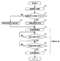
- FIG. 3 shows a liquid feeding processing routine in which the liquid supply apparatus 1 puts a predetermined volume of the liquid F into the processing tank 22 during the operation of the endoscope reprocessing apparatus 20.
- the liquid F is a cleaning liquid. Therefore, the liquid feeding process illustrated in FIG. 3 is performed during the cleaning process performed by the endoscope reprocessing apparatus 20. Each process described below is executed based on the control of the control unit 7.
- step S01 an air venting process is performed as shown in step S01.
- the air venting process is executed based on the flowchart shown in FIG. 4, and details thereof will be described later.
- the liquid supply section 4 is operated until the liquid F is discharged from the second end 3 b of the supply pipe 3, thereby filling the entire supply pipe 3 with the liquid F.
- air is extracted from the supply pipe 3.
- the liquid feeding unit 4 is operated until a specified volume of liquid F is discharged from the second end 3b of the supply pipe 3.
- the designated volume may be a fixed value set in advance or a value calculated by the control unit 7 based on a predetermined program.
- the volume of the liquid F ejected from the second end 3b of the supply pipe 3 is calculated by integrating the detection result of the liquid flow detector 5 which is a flowmeter in this embodiment. Note that the volume of the liquid F ejected from the second end 3 b of the supply pipe 3 may be estimated from the operation duration time of the liquid feeding unit 4.
- step S01 Since the air venting process of step S01 is performed prior to the main liquid feeding process, the supply line 3 at the start of the main liquid feeding process is entirely filled with the liquid F and no air is present. is there. For this reason, bubbles are not mixed with the liquid F discharged from the second end 3b of the supply conduit 3 during the main liquid supply step, and the specified volume of the liquid F is accurately supplied in the main liquid supply step. 3 can be discharged from the second end 3b.
- the time measuring unit 6 stores the time T1 at which liquid feeding in the last liquid feeding process performed immediately before was stopped.
- the time T1 may be the time when the control unit 7 outputs an instruction to stop the operation of the liquid feeding unit 4, or the flow of the liquid F in the supply pipeline 3 is stopped by the liquid flow detection unit 5. It may be the time when this is detected.
- the time when the liquid flow detection unit 5 detects that the flow of the liquid F in the supply pipeline 3 has stopped is defined as time T1.
- the time at which it is detected that the flow of the liquid F in the supply pipe 3 has stopped is set as time T1, so that the preliminary liquid feeding time Tp in step S10 described later can be calculated more accurately. It can be carried out.
- step S01 details of the air venting process of step S01 will be described with reference to the flowchart of FIG.
- step S10 the time measuring unit 6 recognizes the elapsed time Ts from the time when the liquid feeding by the liquid feeding unit 4 was stopped last time to the current time. Specifically, the time measuring unit 6 calculates the elapsed time Ts from the difference between the current time and the time T1 at which it is detected that the flow of the liquid F in the supply supply line 3 is stopped.
- step S10 when the elapsed time Ts can be recognized (YES in step S11), the process proceeds to step S12.
- step S12 the preliminary liquid feeding time Tp is calculated based on the elapsed time Ts.
- the preliminary liquid feeding time Tp becomes longer as the elapsed time Ts becomes longer.
- the preliminary liquid feeding time Tp is determined based on, for example, a reference table as shown in FIG. In the example shown in FIG. 5, the elapsed time Ts and the preliminary liquid feeding time Tp have a linear relationship. However, the preliminary liquid feeding time Tp changes stepwise so as to increase as the elapsed time Ts increases. It may be.
- the preliminary liquid feeding time Tp is a value used in the preliminary liquid feeding process shown in steps S14 to S16 to be executed next.
- the preliminary liquid feeding process of steps S14 to S16 is a process of operating the liquid feeding unit 4 for the preliminary liquid feeding time Tp.
- the liquid feeding unit 4 is configured not to prevent the backflow of the liquid F while the liquid feeding unit 4 is stopped. At the same time, the air falls into the supply pipe 3. Therefore, in the present embodiment, in the preliminary liquid feeding step, the liquid feeding unit 4 is operated for the preliminary liquid feeding time Tp, whereby the air in the supply pipe 3 is extracted and the entire supply pipe 3 is filled with the liquid F. As described above, the specified volume of liquid F can be accurately discharged in the main liquid feeding process from step S02 to step S04 by removing the air from the supply pipe 3.
- the preliminary liquid feeding time Tp is set such that all the air that has entered the supply pipe line 3 by operating the liquid feeding unit 4 is discharged from the supply pipe line 3. Since the relationship between the elapsed time Ts and the preliminary liquid feeding time Tp varies depending on the configuration of the supply pipe 3 and the liquid feeding part 4 that is the constriction part, it is determined by, for example, an experiment performed in advance.
- the preliminary liquid feeding time Tp is set to a constant maximum value Tpmax regardless of the length of the elapsed time Ts.
- Tsmax is the time required for the liquid level of the liquid F in the supply pipe 3 to be lowered to the lowest level.
- the height at which the level of the liquid F in the supply pipeline 3 in the present embodiment is the lowest is the height of the lower end of the second pipeline 3d, that is, the same as the height of the first connection portion 3e. It is.
- the value of Tsmax also varies depending on the configuration of the supply conduit 3 and the liquid delivery unit 4 that is the constriction, and thus is determined, for example, by an experiment performed in advance.
- step S10 If the elapsed time Ts cannot be recognized in step S10 (NO in step S11), the process proceeds to step S13, the preliminary liquid feeding time Tp is set to the maximum value Tpmax, and the preliminary steps in steps S14 to S16 are performed. The liquid feeding process is executed.
- the preliminary liquid feeding time Tp for operating the liquid feeding part 4 in the air venting process is shortened as the elapsed time Ts during which the liquid feeding part 4 is stopped is shorter. To do.
- the amount of the liquid F discharged in the execution of the air venting process can be reduced as the elapsed time Ts during which the liquid feeding unit 4 is stopped is shorter.
- backup liquid feeding time Tp is shortened, so that the elapsed time Ts when the liquid feeding part 4 is a stop state is short, time required for execution of an air venting process can be shortened.
- the liquid supply device 1 and the endoscope reprocessing device 20 according to the present embodiment can reduce the consumption amount of the liquid F in the air venting process and can reduce the time required for the air venting process.
- the liquid feeding unit 4 is described as being stopped between the air venting step of step S01 and the subsequent main liquid feeding steps of step S02 to step S04. Between the liquid feeding process, the liquid feeding section 4 may be continuously operated without stopping.
- control unit 7 changes the preliminary liquid feeding time Tp for operating the liquid feeding unit 4 in the preliminary liquid feeding process based on the elapsed time Ts, but the control unit 7 uses the preliminary time based on the elapsed time Ts.
- the volume Vp of the liquid F fed by the liquid feeding unit 4 may be changed.
- FIG. 6 shows a flowchart of the air venting process of the liquid supply apparatus 1 of the present modification.
- step S12a a preliminary liquid supply volume Vp that is a target value of the volume of the liquid F to be supplied by the liquid supply unit 4 in the preliminary liquid supply process is calculated.
- the preliminary liquid supply volume Vp is set to a value necessary for extracting the air in the supply pipe line 3 and filling the entire supply pipe line 3 with the liquid F in the preliminary liquid supply process to be executed next.
- the preliminary liquid supply volume Vp increases as the elapsed time Ts increases.
- the preliminary liquid supply volume Vp is determined based on, for example, a reference table as shown in FIG.
- the preliminary liquid supply volume Vp is set to a constant maximum value Vpmax regardless of the length of the elapsed time Ts.
- step S15a the volume of the liquid F fed is calculated from the detection result of the liquid flow detection unit 5 that is a flow meter, and the preliminary liquid feeding volume whose volume is the target value. After confirming that Vp has been reached, the process proceeds to step S16 where the liquid feeding unit 4 is stopped.
- the liquid flow detection unit 5 is disposed in the first pipeline 3c. In the present embodiment, as shown in FIG. It arrange
- the liquid flow detection unit 5 When the liquid flow detection unit 5 is arranged in the second pipe 3d as in the present embodiment, depending on the elapsed time Ts after the liquid feeding in the main liquid feeding process is stopped, In some cases, the liquid level of the liquid F falls below the liquid flow detector 5. Therefore, in the preliminary liquid feeding step of the liquid supply apparatus 1 of the present embodiment, as shown in the flowchart of FIG. 9, after the operation of the liquid feeding unit 4 is started in step S20, the liquid feeding unit as shown in step S21. 4 waits until the flow of the liquid F is detected.
- step S21 When the liquid level is above the liquid flow detector 5 at the start of step S21, the flow of the liquid F is immediately detected, and the process proceeds to step S22.
- the liquid level When the liquid level is lower than the liquid flow detection unit 5 at the start of step S21, the liquid level rises to the height of the liquid flow detection unit 5 and the liquid flow detection unit 5 After the flow is detected, the process proceeds to step S22.
- step S22 the operation of the liquid feeding unit 4 is continued for a predetermined preliminary liquid feeding time Tp.
- the liquid level in the supply pipe 3 is always located above the liquid flow detector 5.
- the liquid supply time Tp of the present embodiment is required to remove air existing in the section from the second end 3b of the supply pipe 3 to the place where the liquid flow detector 5 is disposed. It is the operation time of the liquid part 4.
- the elapsed time Ts when the preliminary liquid feeding time Tp reaches the maximum value Tpmax is such that the liquid level of the liquid F remaining in the supply pipe 3 is from the second end 3b to the liquid flow detector 5. Is the time required to drop to the height at which it was placed.
- the liquid feeding in the air venting process may be performed based on the volume of the liquid F detected by the liquid flow detection unit 5. Good.
- the preliminary liquid feeding time Tp is shortened, so that the consumption of the liquid F by the air venting process is reduced.
- the time required for the air venting process can be shortened.
- the liquid supply apparatus 1 according to the first embodiment described above has the first pipeline 3c, which is a section in which the supply pipeline 3 is disposed below the storage tank 2.
- the liquid supply apparatus 1 of the present embodiment shown in FIG. 10 is arranged so that the supply pipeline 3 does not pass below the storage tank 2.
- the entire supply pipeline 3 of the present embodiment is disposed above the bottom surface of the storage tank 3.
- the first end 3 a of the supply pipe 3 is opened inside the storage tank 2, and the second end 3 b is opened outside the storage tank 2.
- the second end 3 b of the supply pipe 3 is disposed above the maximum liquid level of the storage tank 2.
- the supply pipeline 3 is connected to the storage tank 2 at the third connection portion 3f, and has a third pipeline 3g arranged above the third connection portion 3f.
- the 3rd connection part 3f is provided in the upper surface of the storage tank 2, and the area arrange
- the liquid feeding section 4 is arranged at a predetermined distance from the third connection section 3f to the second end section 3b of the third pipeline 3g. When the liquid feeding unit 4 is stopped, the liquid feeding unit 4 becomes a constricted portion that constricts the cross-sectional area of the third conduit 3g.
- the liquid feeding section 4 may be provided with a loose check valve that does not completely block the flow of the fluid in the supply pipe 3 from the second end 3b side to the first end 3a side. Good.
- the liquid flow detection unit 5 is disposed above the liquid supply unit 4, that is, on the second end 3b side of the liquid supply unit 4 of the third pipeline 3g.
- the liquid level of the liquid F in the liquid supply conduit 3 may drop below the liquid flow detection unit 5 depending on the length of the elapsed time Ts. For this reason, in the preliminary liquid feeding process of the liquid supply apparatus 1 of the present embodiment, after starting the operation of the liquid feeding unit 4 in step S20, as in the flowchart shown in FIG. 9 similar to the second embodiment, As shown in step S21, the process waits until the flow of the liquid F is detected in the liquid feeding section 4.
- step S21 When the liquid level is above the liquid flow detector 5 at the start of step S21, the flow of the liquid F is immediately detected, and the process proceeds to step S22.
- the liquid level When the liquid level is lower than the liquid flow detection unit 5 at the start of step S21, the liquid level rises to the height of the liquid flow detection unit 5 and the liquid flow detection unit 5 After the flow is detected, the process proceeds to step S22.
- step S22 the operation of the liquid feeding unit 4 is continued for a predetermined preliminary liquid feeding time Tp.
- the liquid level in the supply pipe 3 is always located above the liquid flow detector 5.
- the liquid supply time Tp of the present embodiment is required to remove air existing in the section from the second end 3b of the supply pipe 3 to the place where the liquid flow detector 5 is disposed. It is the operation time of the liquid part 4.
- the elapsed time Ts when the preliminary liquid feeding time Tp reaches the maximum value Tpmax is such that the liquid level of the liquid F remaining in the supply pipe 3 is from the second end 3b to the liquid flow detector 5. Is the time required to drop to the height at which it was placed.
- the liquid feeding in the air venting process may be performed based on the volume of the liquid F detected by the liquid flow detection unit 5. Good.
- the amount of consumption of the liquid F by the air venting process is shortened because the preliminary liquid feeding time Tp is shortened as the elapsed time Ts during which the liquid feeding unit 4 is stopped is shorter. And the time required for the air venting process can be shortened.
- the liquid supply apparatus 1 is provided in the endoscope reprocessing apparatus 20, but the liquid supply apparatus 1 can also be applied to other apparatuses that handle the liquid F. is there.
- the liquid supply apparatus 1 is provided in a washing machine 40 as shown in FIG.
- the washing machine 40 is a device that cleans clothes and the like disposed in the treatment tank 41 using the liquid F and water that are cleaning liquids.
- the washing machine 40 includes a drum 42 that rotates in the treatment tank 41.
- the drum 42 is rotationally driven by the electric motor 43 and agitates the inside of the processing tank 41.
- the liquid supply apparatus 1 puts the liquid F, which is a cleaning liquid, into the processing tank 41 by a predetermined amount at a predetermined time.
- the configuration and operation of the liquid supply apparatus 1 are the same as those in the first embodiment. Therefore, the liquid supply apparatus 1 according to the present embodiment can reduce the consumption amount of the liquid F consumed in the air venting process and reduce the time required for the air venting process.
- washing machine 40 shown in FIG. 11 includes the liquid supply apparatus 1 similar to that of the first embodiment, the washing machine 40 includes the liquid supply apparatus 1 similar to those of the second and third embodiments. You may have.
- the liquid supply apparatus 1 is provided in a dishwasher 50 as shown in FIG.
- the dishwasher 50 is an apparatus that cleans tableware and the like disposed in the processing tank 51 using the liquid F and water that are cleaning liquids.
- the dishwasher 50 includes a holding shelf 51 a for holding tableware in the treatment tank 51.
- a nozzle 52 for ejecting liquid toward the tableware arranged on the holding shelf 51a is provided.
- a circulation port 51 b connected to the nozzle 52 via a circulation line 53 is provided at the lower part of the treatment tank 51.
- a circulation pump 54 is provided in the circulation line 53. By the operation of the circulation pump 54, the liquid in the processing tank 51 is sucked out from the circulation port 51 b and then ejected from the nozzle 52 through the circulation pipe 53.
- the liquid supply device 1 puts the liquid F, which is a cleaning liquid, into the processing tank 51 by a predetermined amount at a predetermined time.
- the configuration and operation of the liquid supply apparatus 1 are the same as those in the first embodiment. Therefore, the liquid supply apparatus 1 according to the present embodiment can reduce the consumption amount of the liquid F consumed in the air venting process and reduce the time required for the air venting process.
- the dishwasher 50 shown in FIG. 12 includes the liquid supply apparatus 1 similar to that of the first embodiment, but the dishwasher 50 is similar to the liquid supply apparatus of the second and third embodiments. 1 may be provided.
- the present invention is not limited to the above-described embodiment, and can be appropriately changed without departing from the gist or concept of the invention that can be read from the claims and the entire specification.
- An apparatus and an endoscope reprocessing apparatus are also included in the technical scope of the present invention.
Landscapes
- Health & Medical Sciences (AREA)
- Life Sciences & Earth Sciences (AREA)
- Engineering & Computer Science (AREA)
- Surgery (AREA)
- Animal Behavior & Ethology (AREA)
- Veterinary Medicine (AREA)
- Public Health (AREA)
- General Health & Medical Sciences (AREA)
- Physics & Mathematics (AREA)
- General Chemical & Material Sciences (AREA)
- Chemical Kinetics & Catalysis (AREA)
- Chemical & Material Sciences (AREA)
- Pathology (AREA)
- Nuclear Medicine, Radiotherapy & Molecular Imaging (AREA)
- Medical Informatics (AREA)
- Heart & Thoracic Surgery (AREA)
- Biomedical Technology (AREA)
- Radiology & Medical Imaging (AREA)
- Optics & Photonics (AREA)
- Molecular Biology (AREA)
- Biophysics (AREA)
- Mechanical Engineering (AREA)
- Epidemiology (AREA)
- General Physics & Mathematics (AREA)
- Automation & Control Theory (AREA)
- Endoscopes (AREA)
Abstract
La présente invention concerne un dispositif d'alimentation en liquide comprenant : un réservoir de stockage qui stocke un liquide ; un conduit d'alimentation, une première partie d'extrémité de celui-ci est reliée à la cuve de stockage, ledit conduit d'alimentation s'étendant depuis le réservoir de stockage et le liquide qui reste à l'intérieur de celui-ci refluant dans le réservoir de stockage au cours du temps dans une quantité prescrite ; une unité de transport de liquide qui est positionnée sur le réservoir de stockage ou le conduit d'alimentation, et qui transporte le liquide depuis le réservoir de stockage à une seconde partie d'extrémité du conduit d'alimentation ; une unité de chronométrage qui mesure le temps écoulé à partir d'une interruption du transport de liquide par l'unité de transport de liquide ; et une unité de commande qui est reliée à l'unité de transport de liquide et l'unité de chronométrage, et qui entraîne l'unité de transport de liquide pour un temps prescrit en fonction de la longueur du temps écoulé.
Priority Applications (2)
| Application Number | Priority Date | Filing Date | Title |
|---|---|---|---|
| JP2015537863A JP5897226B1 (ja) | 2014-07-16 | 2015-03-19 | 液体供給装置及び内視鏡リプロセス装置 |
| US15/171,180 US9603514B2 (en) | 2014-07-16 | 2016-06-02 | Liquid supplying apparatus and endoscope reprocessing apparatus |
Applications Claiming Priority (2)
| Application Number | Priority Date | Filing Date | Title |
|---|---|---|---|
| JP2014-146203 | 2014-07-16 | ||
| JP2014146203 | 2014-07-16 |
Related Child Applications (1)
| Application Number | Title | Priority Date | Filing Date |
|---|---|---|---|
| US15/171,180 Continuation US9603514B2 (en) | 2014-07-16 | 2016-06-02 | Liquid supplying apparatus and endoscope reprocessing apparatus |
Publications (1)
| Publication Number | Publication Date |
|---|---|
| WO2016009678A1 true WO2016009678A1 (fr) | 2016-01-21 |
Family
ID=55078183
Family Applications (1)
| Application Number | Title | Priority Date | Filing Date |
|---|---|---|---|
| PCT/JP2015/058327 WO2016009678A1 (fr) | 2014-07-16 | 2015-03-19 | Dispositif d'alimentation en liquide et dispositif d'enregistrement d'image |
Country Status (3)
| Country | Link |
|---|---|
| US (1) | US9603514B2 (fr) |
| JP (1) | JP5897226B1 (fr) |
| WO (1) | WO2016009678A1 (fr) |
Cited By (1)
| Publication number | Priority date | Publication date | Assignee | Title |
|---|---|---|---|---|
| WO2019230082A1 (fr) * | 2018-05-31 | 2019-12-05 | オリンパス株式会社 | Dispositif de gestion de nettoyage |
Families Citing this family (1)
| Publication number | Priority date | Publication date | Assignee | Title |
|---|---|---|---|---|
| KR102346529B1 (ko) * | 2019-06-24 | 2021-12-31 | 세메스 주식회사 | 액 공급 유닛, 그리고 이를 가지는 기판 처리 장치 및 방법 |
Citations (3)
| Publication number | Priority date | Publication date | Assignee | Title |
|---|---|---|---|---|
| JPS59141930A (ja) * | 1983-02-04 | 1984-08-14 | オリンパス光学工業株式会社 | 内視鏡用洗滌装置 |
| JPH10309254A (ja) * | 1997-05-13 | 1998-11-24 | Olympus Optical Co Ltd | 内視鏡洗滌消毒装置 |
| JP2010057752A (ja) * | 2008-09-04 | 2010-03-18 | Fujifilm Corp | 内視鏡洗浄消毒装置 |
Family Cites Families (1)
| Publication number | Priority date | Publication date | Assignee | Title |
|---|---|---|---|---|
| WO2013031388A1 (fr) * | 2011-08-30 | 2013-03-07 | オリンパスメディカルシステムズ株式会社 | Dispositif de traitement d'endoscope |
-
2015
- 2015-03-19 JP JP2015537863A patent/JP5897226B1/ja active Active
- 2015-03-19 WO PCT/JP2015/058327 patent/WO2016009678A1/fr active Application Filing
-
2016
- 2016-06-02 US US15/171,180 patent/US9603514B2/en active Active
Patent Citations (3)
| Publication number | Priority date | Publication date | Assignee | Title |
|---|---|---|---|---|
| JPS59141930A (ja) * | 1983-02-04 | 1984-08-14 | オリンパス光学工業株式会社 | 内視鏡用洗滌装置 |
| JPH10309254A (ja) * | 1997-05-13 | 1998-11-24 | Olympus Optical Co Ltd | 内視鏡洗滌消毒装置 |
| JP2010057752A (ja) * | 2008-09-04 | 2010-03-18 | Fujifilm Corp | 内視鏡洗浄消毒装置 |
Cited By (3)
| Publication number | Priority date | Publication date | Assignee | Title |
|---|---|---|---|---|
| WO2019230082A1 (fr) * | 2018-05-31 | 2019-12-05 | オリンパス株式会社 | Dispositif de gestion de nettoyage |
| JPWO2019230082A1 (ja) * | 2018-05-31 | 2021-03-11 | オリンパス株式会社 | 洗浄管理装置および洗浄管理方法 |
| US11455509B2 (en) | 2018-05-31 | 2022-09-27 | Olympus Corporation | Cleaning management apparatus and cleaning management method |
Also Published As
| Publication number | Publication date |
|---|---|
| JP5897226B1 (ja) | 2016-03-30 |
| JPWO2016009678A1 (ja) | 2017-04-27 |
| US9603514B2 (en) | 2017-03-28 |
| US20160270646A1 (en) | 2016-09-22 |
Similar Documents
| Publication | Publication Date | Title |
|---|---|---|
| US8763516B2 (en) | Device for feeding milk | |
| JP7385793B2 (ja) | 内視鏡のチャネルを反復的に充填及びパージするための機器及び方法 | |
| KR101287745B1 (ko) | 자동 계량공급 시스템을 구비한 물 사용 가전 기기 및 자동 계량공급 방법 | |
| JP5885894B1 (ja) | 内視鏡リプロセッサ | |
| US20090044845A1 (en) | Endoscope reprocessor | |
| CA2571077A1 (fr) | Lave-vaisselle et procede de fonctionnement d'un lave-vaisselle | |
| TWI755554B (zh) | 洗衣機 | |
| JP5897226B1 (ja) | 液体供給装置及び内視鏡リプロセス装置 | |
| US9968973B2 (en) | Endoscope reprocessor | |
| CN108430298A (zh) | 判定在用于洗涤和冲洗物品的器具运行中断间期是否向器具的集水槽中添加了处理用水 | |
| JP5191225B2 (ja) | 内視鏡洗浄消毒装置 | |
| WO2015132998A1 (fr) | Procédé de nettoyage et de stérilisation utilisant un dispositif de nettoyage et de stérilisation d'endoscope | |
| WO2016027520A1 (fr) | Dispositif de retraitement d'endoscope | |
| JP5289782B2 (ja) | 内視鏡洗滌消毒装置 | |
| JP5966097B1 (ja) | 内視鏡リプロセッサ | |
| JP2022174294A (ja) | 内視鏡のチャネルの充填およびパージを非同期的に同時に行う器械および方法 | |
| JP2008142420A (ja) | 内視鏡洗浄消毒装置 | |
| CN108430296A (zh) | 确定用于洗涤和冲洗物品的器具的循环泵中是否存在处理用水的方法以及用于洗涤和冲洗物品的器具 | |
| JP6138398B1 (ja) | 流体供給装置および内視鏡リプロセッサ | |
| JP3848644B2 (ja) | 食材洗浄装置 | |
| JP5885635B2 (ja) | 内視鏡洗浄消毒装置 | |
| WO2017134891A1 (fr) | Dispositif de distribution de fluide et dispositif de retraitement d'endoscope | |
| JP6472114B1 (ja) | 内視鏡リプロセッサ | |
| JP5753332B1 (ja) | 内視鏡洗浄消毒装置を用いた洗浄消毒方法 | |
| DE202005017252U1 (de) | Reinigungssystem für einen Ofen |
Legal Events
| Date | Code | Title | Description |
|---|---|---|---|
| ENP | Entry into the national phase |
Ref document number: 2015537863 Country of ref document: JP Kind code of ref document: A |
|
| 121 | Ep: the epo has been informed by wipo that ep was designated in this application |
Ref document number: 15821613 Country of ref document: EP Kind code of ref document: A1 |
|
| NENP | Non-entry into the national phase |
Ref country code: DE |
|
| 122 | Ep: pct application non-entry in european phase |
Ref document number: 15821613 Country of ref document: EP Kind code of ref document: A1 |