WO2016009534A1 - 撮像センサおよびそれを用いたデジタルカメラおよびその制御方法 - Google Patents
撮像センサおよびそれを用いたデジタルカメラおよびその制御方法 Download PDFInfo
- Publication number
- WO2016009534A1 WO2016009534A1 PCT/JP2014/069075 JP2014069075W WO2016009534A1 WO 2016009534 A1 WO2016009534 A1 WO 2016009534A1 JP 2014069075 W JP2014069075 W JP 2014069075W WO 2016009534 A1 WO2016009534 A1 WO 2016009534A1
- Authority
- WO
- WIPO (PCT)
- Prior art keywords
- pixels
- pixel group
- image
- pixel
- imaging sensor
- Prior art date
- Legal status (The legal status is an assumption and is not a legal conclusion. Google has not performed a legal analysis and makes no representation as to the accuracy of the status listed.)
- Ceased
Links
Images




Classifications
-
- H—ELECTRICITY
- H04—ELECTRIC COMMUNICATION TECHNIQUE
- H04N—PICTORIAL COMMUNICATION, e.g. TELEVISION
- H04N25/00—Circuitry of solid-state image sensors [SSIS]; Control thereof
- H04N25/40—Extracting pixel data from image sensors by controlling scanning circuits, e.g. by modifying the number of pixels sampled or to be sampled
- H04N25/42—Extracting pixel data from image sensors by controlling scanning circuits, e.g. by modifying the number of pixels sampled or to be sampled by switching between different modes of operation using different resolutions or aspect ratios, e.g. switching between interlaced and non-interlaced mode
Definitions
- the present invention relates to display of a digital camera, and more particularly to display of a subject during still image shooting.
- a digital camera that obtains a two-dimensional captured image by projecting an image of an object through an imaging sensor, which is an aggregate of a plurality of pixels, and measuring the amount of light irradiated to each pixel. It is popular.
- optical viewfinders are used in the age of film cameras as a viewfinder for tracking the subject at the time of shooting, and the type of optical viewfinder is provided at a position different from the shooting lens used in compact cameras.
- There is a method and a method such as a single-lens reflex camera in which an image actually reflected on a film can be seen in advance by projecting light incident from a photographing lens onto a focus glass.
- the light directly incident on the image sensor before photographing can be used as a viewfinder.
- the image signal input from the image sensor is installed on the back of the digital camera (hereinafter referred to as LCD: Liquid Crystal Display) or a position corresponding to the single lens reflex focusing glass using a liquid crystal display.
- the image can be viewed with an electronic viewfinder (hereinafter referred to as EVF: Electronic View Finder) that displays a large screen image 1 m ahead of the naked eye using a lens.
- EVF Electronic View Finder
- the current digital still camera is capable of capturing moving images, and generally requires a still image to be captured having a considerably larger number of pixels than the number of displayable pixels of the liquid crystal display. It is a specification.
- the moving image displayed on the liquid crystal display is, for example, 1920 ⁇ 1080 pixels corresponding to a high-vision camera
- the shootable still image is, for example, 4000 ⁇ 3000 pixels, which is several times as many pixels as the moving image. Get an image.
- the time required to read out a color image of 4600 ⁇ 3400 pixels with an image sensor of 16 million pixels is approximately 0. It takes 1 second, and during that time, you cannot see the viewfinder image using the image sensor. Therefore, the screen is blacked out for about 0.1 seconds after shooting by pressing the shutter button.
- cellular phones, smartphones, and some compact digital cameras are designed to continue displaying still images on a liquid crystal display for a predetermined time after shooting.
- the time of 0.1 seconds described above is about 10 frames / second for the continuous shooting function of the digital camera of this example, and the total time for shooting one frame and reading from the sensor is about 1/10 seconds. It is gained from being.
- Patent Document 1 Japanese Patent Application Laid-Open No. 2011-259102
- Patent Document 1 the entire pixel screen of the solid-state imaging device has a four-block configuration in units of one line in the vertical direction, and the blocks are arranged, and each of them is f-1 (field 1), f-2, f- 3 and f-4, and when reading all pixels, after reading f-1, when reading f-2 to f-4, f-1 performs a new shooting
- f-2 Disclosed is a technology that can update a moving image captured in 1/4 of the time required to read the full screen of the solid-state imaging device, although the resolution in the vertical direction is 1/4 during the time to read f-4.
- the frame rate of a moving image handled in the current television is 60 fps. Further, in the future 4K digital television standard, it is required to display a moving image at a speed of 120 fps, and the speed of 40 fps belongs to the slower one that does not hinder visual recognition. Further, even in the method of Patent Document 1, when the number of pixels of the sensor further increases, the frame rate tends to decrease.
- An object of the present invention is to provide an apparatus that allows a user to visually recognize an object to be photographed with a finder at a high frame rate, and can continue to visually recognize a subject with the finder even when taking a still image. .
- the present invention includes a plurality of means for solving the above problems.
- a method of controlling a digital camera that acquires an image obtained by converting an optical image into an electrical signal by an image sensor,
- the pixels constituting the image sensor are configured by first and second pixel groups having different drive timings and readout paths, and the first pixel group has light incident and readout speeds in the second pixel group.
- the pixels of the first pixel group are arranged at a ratio of one for n pixels in the horizontal direction of the pixels constituting the image sensor, and one for m pixels in the vertical direction.
- the pixel group is composed of pixels excluding the first pixel group of the pixels constituting the image sensor, and the image information acquired from the first pixel group is displayed as a continuous moving image on the display device, and the shutter When the button is pressed down, the image information acquired from the second pixel group is read out, the signal processing is performed, and the display of the moving image is continued.
- an object to be photographed by a user can be visually recognized with a finder at a high frame rate, and the subject can be visually recognized with a finder even when a still image is captured.
- FIG. 1 is a configuration diagram illustrating the configuration and operation of a digital camera in Embodiment 1.
- FIG. It is explanatory drawing explaining the structure of the imaging sensor in Example 1.
- FIG. FIG. 6 is an explanatory diagram illustrating a method for extracting information for a still image and information for EVF from information acquired by the imaging sensor according to the first embodiment.
- FIG. 3 is an explanatory diagram illustrating a method for generating still image data from information acquired by the imaging sensor according to the first embodiment.
- FIG. 3 is an explanatory diagram illustrating time-series data of light incident on a sensor and signal output when EVF information and still image information are extracted from the imaging sensor according to the first embodiment.
- FIG. 6 is a configuration diagram illustrating the configuration and operation of a digital camera according to a second embodiment.
- FIG. 10 is a configuration diagram illustrating the configuration and operation of a digital camera in Embodiment 3. It is explanatory drawing which showed the time series data of the light-incidence to a sensor when taking out the information for EVF, and the information for still images from the imaging sensor in Example 3, and a signal output.
- FIG. 1 is a configuration diagram illustrating the configuration and operation of a digital camera in the present embodiment.
- a digital camera is a device that projects an image of a subject through a lens on an imaging sensor that is an assembly of a plurality of pixels arranged in a two-dimensional manner on an imaging surface, and converts an optical image into an electrical signal to acquire a captured image. .
- the digital camera performs shooting using a subject 1040, which is a moving object such as a bird flying at high speed, as a subject to be photographed.
- the user can view the subject image formed on the image sensor 1010 through the objective lens 1020 having a triplet structure while viewing the image displayed on the EVF 1030 or the LCD 1000 so that the subject image is within the range of the image sensor 1010.
- the subject is tracked while changing the direction of the digital camera.
- the objective lens 1020 moves to focus on the subject 1040 (autofocus, hereinafter referred to as AF), and the image sensor 1010 moves the subject.
- AF autofocus
- a video is captured and a captured image is recorded in an external memory described later.
- the number of pixels of the image sensor 1010 is 16000 ⁇ 12000 ⁇ 3 pixels.
- the data of all the pixels is read by the signal processing circuit DSP-B1050, and the data is compressed by the encoder 1070 in a still image compression format such as JPEG, and the memory 1080 such as a detachable SD memory is used. It is assumed that it takes about 1/10 second to read from the image sensor. In this case, when continuous shooting is performed with this digital camera, continuous shooting at a considerably high speed of 10 frames per second is possible. In this case, the image sensor 1010 acquires an image and outputs it as data in a normal method.
- the finder image output to the EVF 1030 or the LCD 1000 is 10 frames per second (10 fps). This speed is about the same speed as the finder of a digital camera installed in an early mobile phone. Further, since a new subject image cannot be obtained from the image sensor after reading from the image sensor 1010 after the still image is captured and stored in the memory 1080, the screen of the EVF 1030 or the LCD 1000 is blacked out. In particular, when shooting while tracking a fast-moving subject, the subject may escape from the viewfinder, making it impossible to continue shooting.
- the image sensor 1010 has a high-speed reading mode.
- the frame rate is higher (for example, 30 fps). It is possible to see.
- the frame rate drops to 10 fps.
- the method described later in FIG. 2 is used to display a moving image as a viewfinder on the EVF 1030 or the LCD 1000 at a high frame rate.
- the image sensor 1010 has pixels, which are read out by the signal processing circuit DSP-A 1060 and sent to the EVF 1030 or the LCD 1000 so that the subject can be tracked at a high frame rate even during still image shooting.
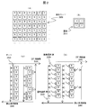
- FIG. 2 is an explanatory diagram for explaining the structure of the image sensor in the present embodiment.
- 2A shows a pixel configuration of the image sensor 2000.
- FIG. Pixel A is a pixel that is output toward the viewfinder, and B is a pixel that is used when shooting a still image.
- the two types of pixels have a structure in which the sensor drive timing and readout path are all different systems, and two independent types of sensors are mixed on the same sensor surface.
- the pixels A are distributed in a ratio of one to four pixels of the image sensor pixels in both the horizontal and vertical directions.
- FIG. 2B shows details of the pixel A and the pixel B.
- These pixels are color sensors, and one pixel 2010 is actually composed of four light receiving sensors.
- the sensor is provided with three color filters of R, G, and B, and the three primary colors of light can be simultaneously captured by one pixel.
- FIG. 2C shows an example in which the present imaging sensor is a CCD, and the output from each pixel is read out in the order of the pixels through the gate 2020.
- the output from the pixel A reads image information as an EVF image 2030
- the output from the pixel B reads image information as a still image pixel 2040.
- the still image pixel 2040 is read out at a rate of 10 frames per second.
- the EVF image 2030 is read out at a high speed regardless of the readout speed of the pixel B, and is read into the above-described EVF or LCD.
- a moving image can be displayed at high speed.
- FIG. 2D shows an example in which the imaging sensor is a MOS.
- the MOS can read an arbitrary pixel by selecting the timing of reading from each pixel using the pixel selection SW 2020 for each pixel. Normally, this selection is read out in the order of pixels as in the case of the CCD.
- the pixel A is read at a high speed regardless of the reading of the pixel B, so that a moving image can be displayed on the EVF or the LCD at a high speed as in the above description.
- the number of pixels of the image acquired by the pixel A on the image sensor conforms to the current image format of high-definition digital television, and may be, for example, 1920 ⁇ 1080 pixels ⁇ 60 fps or 1440 ⁇ 1080 pixels ⁇ 60 fps. Good.
- FIG. 3 is an explanatory diagram showing a method for extracting information for a still image and information for EVF from information acquired by the image sensor in the present embodiment.
- 3A is the same as FIG. 2A.
- FIG. 3B shows the still image pixel 3010 on the acquired image sensor, and the portion corresponding to the pixel A is in a state where the pixel is missing.
- FIG. 3C shows an EVF pixel on the image sensor, which is composed of only the pixel A, so that the number of pixels is smaller than all the pixels on the sensor. Specifically, in the case where all the pixels are 16000 ⁇ 12000, if they are arranged in a ratio of one to four of all the sensor pixels both horizontally and vertically, it is 4000 ⁇ 3000 pixels (the same as the number of pixels of 4K television). Since this small number of pixels is read, the pixel A can be read at a high speed.
- 4K digital television broadcasting has a standard of displaying a 4000 ⁇ 3000 image at 120 fps, and in this method, a moving image of a digital television can be taken using the pixel A, and much more than the number of pixels of the digital television. High-resolution still images can be acquired simultaneously.
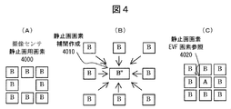
- FIG. 4 is an explanatory diagram showing a method of generating still image data from information acquired by the image sensor in the present embodiment. 4A is the same as FIG. 3B.
- FIG. 4B shows a method of constructing all the pixels of the high-definition still image by interpolating the part where the position of the pixel A is missing from the surrounding pixels to generate the pixel B ′′. Because the part is interpolated, the resolution of the high-definition still image decreases at a rate of 1 in 4 pixels both horizontally and vertically, but the captured image is JPEG compressed by discrete cosine transform, so the frequency component of the captured image is maximum. Except for extremely high cases, image quality is unlikely to deteriorate even when this interpolation calculation is used.
- the current general digital still camera covers even if pixels of the image sensor are mixed to some extent by interpolating them to create a still image, thereby improving the mass production efficiency of the image sensor. Therefore, even if the pixel interpolation is performed by the method as in this embodiment, the influence is small.
- FIG. 4C shows a method of constructing all pixels of a high-definition still image using the pixel A read out for EVF from the portion where the position of the pixel A is missing.
- the shutter speed of the pixel B is also high, so both shutter speeds are close to each other and a high-definition still image can be constructed.
- FIG. 5 is an explanatory diagram showing time series data of light incident on the image sensor and signal output as drive timing when the EVF information and the still image information are extracted from the image sensor in the present embodiment. .
- FIG. 5A is a timing diagram in the time axis direction showing the relationship between the received light and the transfer of the captured video as the drive timing of the EVF pixel A.
- the pixel is read according to the EVF image transfer timing 5020.
- the light of the next frame is acquired by the pixel A. By continuing this continuously, a moving image with a high frame rate of 120 fps can be acquired.
- FIG. 5B illustrates the acquisition of a still image.
- the pixel B starts to receive light as a driving timing, and after receiving light of an appropriate exposure level at a predetermined shutter speed 5060, that is, at a still image pixel incident light timing 5030, Reading is performed according to the pixel image transfer timing 5040. Since the shutter opening time and transfer timing operate independently of the pixel A that outputs a moving image to the EVF, the image for EVF operates at 120 fps even during shooting of a still image, and the subject is continued in the EVF. Observe and track.
- the pixel A is described as being disposed at a ratio of one to four of the imaging sensor pixels in both the horizontal and vertical directions, but the present invention is not limited to this.
- the ratio of one to n pixels in the horizontal direction is provided.
- Arrangement that is, 1 / n pixels in the horizontal direction of the image sensor, and 1 in m pixels in the vertical direction, that is, 1 / m pixel in the vertical direction of the image sensor may be used.
- the digital camera has been described.
- this embodiment can also be applied to devices having a digital camera function such as a mobile phone, a smartphone, and a tablet.
- the present embodiment for example, even when a bird flying at high speed is used as a subject, it is possible to achieve optimum focus on the subject by tracking the bird and continuing to recognize it as a subject.
- tracking can be continued even when the subject is removed from the viewfinder of the digital camera, shooting can be performed without losing sight of the subject. That is, it is possible to provide an apparatus that allows a user to visually recognize an object to be photographed with a viewfinder at a high frame rate, and can continue to visually recognize a subject with the viewfinder even when a still image is photographed.
- FIG. 6 is a configuration diagram illustrating the configuration and operation of the digital camera in the present embodiment.
- the basic configuration is the same as in FIG.
- the moving image output to the EVF or LCD has the number of pixels and the frame rate in conformity with the moving image format of the digital television. Therefore, the moving image acquired by the pixel A is obtained by the encoder 6090.
- the encoder 6090 For example, MPEG4 and H.264.
- the present embodiment is characterized in that it is compressed in accordance with a moving image compression format such as H.264 and stored in the memory 6100.
- the memory 6100 is separated from the memory 6070 for recording a still image, but these may be the same removable memory, the still image is a removable SD memory card, and the moving image is built in the digital camera. It may be stored on the hard disk.
- a video during still image shooting can be stored in a memory as a moving image.
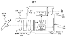
- FIG. 7 is a configuration diagram illustrating the configuration and operation of the digital camera in the present embodiment.
- FIG. 7 the basic configuration is the same as in FIG. This embodiment is characterized in that a mechanical shutter 7090 such as a focal plane shutter is provided in front of the image sensor 7010.
- a mechanical shutter 7090 such as a focal plane shutter is provided in front of the image sensor 7010.
- the timing at which each pixel receives light differs according to the order in which the pixels are read. Therefore, when a moving object is photographed, the acquired still image may be distorted.
- a mechanical shutter is used to simultaneously give light to all the pixels of the MOS sensor, and then outside light is prevented by the mechanical shutter, so that even if the pixels are read sequentially, the image is taken. The image is not distorted.
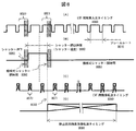
- FIG. 8 is an explanatory diagram showing time-series data of light incident on the image sensor and signal output when the EVF information and the still image information are extracted from the image sensor 7010 in the present embodiment.
- the timings (B) and (D) are the same as the timing for acquiring the still image in FIG.
- the mechanical shutter 7090 is once closed to completely block the light entering the image sensor, and the light acquired by the image sensor is reset before the shutter.
- Light is given to the image sensor according to the shutter opening time 5060 corresponding to the speed, and then the mechanical shutter is closed again.
- the amount of light accumulated by the sensor is fixed to the amount of light received during the time by the mechanical shutter, and is read out at the time of the still image pixel image transfer timing in FIG. Note that the second closing period of the mechanical shutter may be omitted.
- FIG. 8A shows the acquisition of a high-speed frame rate image to be output to the EVF
- FIG. 8C shows the readout timing.
- the pixel A cannot receive light (8020, 8021), and a continuous moving image cannot be sent to the EVF (8070, 8071).
- the shutter curtain of the mechanical shutter captures images at a high speed of about 1/250.
- the sensor can be completely covered and opened completely. Therefore, the time for blocking the pixel A with the mechanical shutter is 1/250 seconds, and even when a moving image is acquired at a frame rate of 120 fps, the time for blocking with the mechanical shutter is one frame or less.
- the frame rate of the current general high-definition television (maximum number of pixels 1920 ⁇ 1080) is 60 fps, and there is no problem in observing and tracking the subject even if 120 fps drops to 60 fps for a moment during shooting.
Landscapes
- Engineering & Computer Science (AREA)
- Multimedia (AREA)
- Signal Processing (AREA)
- Studio Devices (AREA)
Abstract
ユーザーが撮影しようとしている対象物を、高速フレームレートにてファインダーで視認し、さらに静止画像の撮影時もファインダーで被写体を視認し続けることが出来る装置を提供する。 そのために、デジタルカメラに用いられる撮像センサとして、撮像センサを構成する画素は、駆動タイミング、読出し経路が別系統である第1、第2の画素グループにより構成され、第1の画素グループは、入光および読出し速度が、第2の画素グループに比べて速く、第1の画素グループの画素は、撮像センサを構成する画素の横方向にn画素に1つの割合で配置され、縦方向にm画素に1つの割合で配置されており、第2の画素グループは、撮像センサを構成する画素の第1の画素グループを除いた画素で構成する。これにより、第2の画素グループから取得した静止画撮影時にも、第1の画素グループから取得した画像情報を連続した動画像として表示できる。
Description
本発明は、デジタルカメラの表示に係り、特に静止画撮影時の被写体表示に関する。
被写体の映像を、複数画素の集合体である撮像センサに、レンズを通して映像投射させ、各画素に照射された光の量を測定することにより、二次元の撮像画像を取得するデジタル方式のカメラが普及している。
また、撮影時に被写体を追尾するファインダーとして、光学式ファインダーがフィルムカメラの時代には使われており、その種別はコンパクトカメラなどで採用されている撮影レンズとは異なる位置に光学式のファインダーを設ける方法や、一眼レフカメラのように、撮影レンズから入射した光をピントグラスに投射することで、実際にフィルムに写るイメージを事前に見ることが出来るものなどがある。
ここで、デジタルカメラの場合は、フィルムではなく電子式撮像センサを用いるため、撮影前に直接撮像センサに入射した光をファインダーとして利用することが出来る。この撮像センサから入力した画像信号は、液晶ディスプレイを用いて、デジタルカメラの背面液晶ディスプレイ(以下、LCD:Liquid Crystal Displayと呼称)や、前記一眼レフのピントグラスに相当する位置に液晶ディスプレイを設置し、レンズを用いて空間上にて肉眼より例えば1m先に大画面の映像を表示する電子ビューファインダー(以下、EVF:Electronic View Finderと呼称)にて見ることが出来る。
ここで、現状のデジタルスチルカメラは、動画像の撮影も可能になっており、撮影する静止画像の画素数が前記液晶ディスプレイの表示可能画素数に比べてかなり多いものが一般的に要求される仕様となっている。具体的には、液晶ディスプレイに表示する動画像が例えばハイビジョンカメラに相当する1920×1080画素であり、撮影可能な静止画は例えば4000×3000画素と、前記動画像よりも数倍多い画素数の画像を取得する。
ところで、撮像センサから撮影した画像の光情報をデジタル化して読み出すには、ある程度の時間がかかり、例えば1600万画素の撮像センサで、4600x3400画素のカラー画像を読み出すのに必要な時間は、およそ0.1秒かかり、その間、撮像センサを用いてファインダー画像を見ることは出来ない。そのために、シャッターボタンを押して撮影してから約0.1秒間は、画面がブラックアウトする。このブラックアウトを避ける目的もあって、携帯電話やスマートフォンや一部のコンパクトデジタルカメラでは、撮影をしてから所定時間は撮影した静止画像を液晶ディスプレイに表示し続けるような仕様となっている。この場合、撮影をしてからすぐ次の撮影を行うような場合、具体的には野鳥や鉄道などの動くものを撮影するときの連写を行うのに対して、その間にファインダーで被写体を見ることが出来ないため、撮影に大きな支障をきたす。尚、前記した0.1秒という時間は、この例のデジタルカメラの連写機能が約10コマ/秒であり、一コマの撮影とセンサからの読み出し等の時間の総合がおよそ1/10秒であることから得ている。
このような連写におけるブラックアウトを避けるための先行技術として、例えば、特開2011-259102号公報(特許文献1)がある。特許文献1では、固体撮像装置の全画素画面を、垂直方向に1ラインを単位とする4つのブロック構成とし、そのブロックを並べて、各々をf-1(フィールド1)、f-2、f-3、f-4とグループ分類し、全画素を読み出す際に、f-1を読み出した後、f-2~f-4を読み出す際に、f-1は新たな撮影を行い、f-2~f-4を読み出す時間の間、垂直方向は1/4の解像度になるものの、固体撮像装置全画面の読出しにかかる時間の1/4で撮影した動画像を更新することが出来る技術が開示されている。ここで、この方式を前記の具体的な連写速度に当てはめてみると、全画面の読出しに1/10秒かかる場合、その1/4の1/40秒=40fps(frame per sec)の速度で被写体を視認しつつ静止画像の撮影をすることが可能となる。
ところで、現状のテレビジョンで扱っている動画像のフレームレートは60fpsである。さらに将来の4Kディジタルテレビジョンの規格では120fpsの速度で動画像を表示することが求められており、40fpsという速度は視認に支障のない速度としては遅いほうに属する。また、特許文献1の方式でもセンサの画素数がさらに多くなったときは、フレームレートは低下する方向になる。
本発明の目的は、ユーザーが撮影しようとしている対象物を、高速フレームレートにてファインダーで視認し、さらに静止画像の撮影時もファインダーで被写体を視認し続けることが出来る装置を提供することである。
本発明の目的は、ユーザーが撮影しようとしている対象物を、高速フレームレートにてファインダーで視認し、さらに静止画像の撮影時もファインダーで被写体を視認し続けることが出来る装置を提供することである。
上記課題を解決するために、例えば請求の範囲に記載の構成を採用する。本発明は上記課題を解決する手段を複数含んでいるが、その一例を挙げるならば、
撮像センサにより光学像を電気信号に変換して撮像画像を取得するデジタルカメラの制御方法であって、
撮像センサを構成する画素は、駆動タイミング、読出し経路が別系統である第1、第2の画素グループにより構成され、第1の画素グループは、入光および読出し速度が、第2の画素グループに比べて速く、第1の画素グループの画素は、撮像センサを構成する画素の横方向にn画素に1つの割合で配置され、縦方向にm画素に1つの割合で配置されており、第2の画素グループは、撮像センサを構成する画素の第1の画素グループを除いた画素で構成されており、第1の画素グループから取得した画像情報を表示装置に連続した動画像として表示し、シャッターボタンを押し下げた時、動画像の表示を継続しつつ、第2の画素グループから取得した画像情報を読み出して信号処理を行い記録媒体に保存する構成とした。
撮像センサにより光学像を電気信号に変換して撮像画像を取得するデジタルカメラの制御方法であって、
撮像センサを構成する画素は、駆動タイミング、読出し経路が別系統である第1、第2の画素グループにより構成され、第1の画素グループは、入光および読出し速度が、第2の画素グループに比べて速く、第1の画素グループの画素は、撮像センサを構成する画素の横方向にn画素に1つの割合で配置され、縦方向にm画素に1つの割合で配置されており、第2の画素グループは、撮像センサを構成する画素の第1の画素グループを除いた画素で構成されており、第1の画素グループから取得した画像情報を表示装置に連続した動画像として表示し、シャッターボタンを押し下げた時、動画像の表示を継続しつつ、第2の画素グループから取得した画像情報を読み出して信号処理を行い記録媒体に保存する構成とした。
本発明によれば、ユーザーが撮影しようとしている対象物を、高速フレームレートにてファインダーで視認し、さらに静止画像の撮影時もファインダーで被写体を視認し続けることが出来る。
以下、本発明の実施例について図面を用いて説明する。
図1は、本実施例における、デジタルカメラの構成及び動作を説明する構成図である。デジタルカメラは、撮像面に2次元状に配列された複数画素の集合体である撮像センサにレンズを通して被写体の映像を投射させ、光学像を電気信号に変換して撮像画像を取得する装置である。
ここでデジタルカメラは、撮影する対象物として、高速で飛翔する鳥のような移動体である被写体1040を被写体として撮影を行う場合を想定している。
ユーザーは、例えばトリプレット構成の対物レンズ1020を通して、撮像センサ1010に結像された被写体映像を、EVF1030もしくはLCD1000に表示される映像を見つつ、撮像センサ1010の範囲内に被写体映像が入るように、デジタルカメラの方向を変えつつ被写体を追尾していく。
そして適当な時点で、(図示しない)シャッターボタンをユーザーが押し下げることで、対物レンズ1020は、被写体1040にピントが合うように移動し(オートフォーカス。以下、AFと呼称)、撮像センサ1010は被写体映像を取り込んで、後述する外部メモリに、撮像画像を記録する。
ここで、例えば撮像センサ1010の画素数が、16000×12000×3色の画素数を有しているとする。このデジタルカメラは、その全画素のデータを信号処理回路DSP-B1050にて読出し、それをエンコーダ1070によりJPEG等の静止画像圧縮フォーマットにてデータ圧縮し、例えば着脱式のSDメモリのようなメモリ1080に保存するが、その撮像センサからの読み出しにかかる時間が約1/10秒かかるとする。この場合、このデジタルカメラで連写を行う際には毎秒10コマというかなり速い速度での連写が可能となるが、その場合、通常の方法では撮像センサ1010が画像を取得し、データとして出力するのに、一コマあたり1/10秒かかるため、EVF1030やLCD1000に出力されるファインダー映像は毎秒10コマ(10fps)となる。この速度は初期の携帯電話に搭載されたデジタルカメラのファインダーの速度程度で、スムーズに動画をファインダーで見ることが出来ない。また静止画像の撮影後の撮像センサ1010からの読出しからメモリ1080に保存するまでの間は、撮像センサからの新たな被写体画像を得ることが出来ないため、EVF1030もしくはLCD1000の画面がブラックアウトしてしまい、特に高速で動く被写体を追尾しつつ撮影する時には、被写体をファインダーから逃がしてしまい、撮影続行が出来なくなる状況が発生する。
一般には、撮像センサ1010には高速読出しモードがあり、撮像センサ全面ではなくライン単位で間引いた画像を読み出すことで、撮影前に被写体をファインダーで見るときには、もっと速いフレームレート(例えば30fpsなど)で見ることが可能である。しかし実際に撮影をしつつ被写体を追尾する場合には、上記説明のように、撮像センサ1010全面の全画素(この場合、16000×12000画素×3色)を読み出すため、ファインダーで被写体を見るときは、そのフレームレートは10fpsまで低下してしまう。そしてその1/10秒の間、EVF1030もしくはLCD1000の画面がブラックアウトしてしまう問題も同様に発生する。
本実施例では図2以降で後述する方法を用いて、静止画像を撮影するときの撮像センサ1010の画素を読み出す他に、EVF1030もしくはLCD1000にファインダーとしての動画像を速いフレームレートで表示するための画素を撮像センサ1010が有し、それを信号処理回路DSP-A1060にて読出し、EVF1030もしくはLCD1000に送ることで、静止画像の撮影中でも高速フレームレートでの被写体の追尾が可能なようにしている。
図2は、本実施例における、撮像センサの構造を説明する説明図である。図2において、(A)は撮像センサ2000の画素構成を示している。画素Aはファインダーに向けて出力する画素、Bは静止画を撮影するときに使われる画素である。この二種類の画素は、センサの駆動タイミング、読出し経路がすべて別系統であり、独立した二種類のセンサが同一センサ面に混在する構造となっている。ここでは画素Aは水平・垂直共に撮像センサ画素の4画素に1つの割合で分布している。
図2(B)は画素A及び画素Bの詳細である。これらの画素はカラーセンサであり、実際には一つの画素2010が4つの受光センサにより構成されている。そのセンサにはR、G、Bの三色のカラーフィルターがかけられており、光の三原色を一つの画素で同時に取り込むことが出来る。ここでR、G、Bの三色のうち、人間の目がもっとも敏感である明るさは、Y=0.3×R+0.6×G+0.1×Bと、Gがもっとも大きな比率を占めているので、Gのセンサは二つあり、撮影する光の情報をよりよく取得することが出来る。
図2(C)は、本撮像センサがCCDの場合の例であり、各画素からの出力はゲート2020を通して画素の順番に読みだされる。ここで画素Aからの出力はEVF用画像2030として画像情報が読み出され、画素Bからの出力は静止画用画素2040として画像情報が読み出される。静止画用画素2040は図1で前述したように、毎秒10コマの速度で読み出されるが、EVF用画像2030は、画素Bの読み出し速度とは無関係に、高速で読出し、前述のEVFもしくはLCDに高速で動画像を表示することが出来る。
図2(D)は、本撮像センサがMOSの場合の例である。MOSは各画素から読み出すタイミングを画素毎に画素選択SW2020を用いて選択することで、任意の画素を読み出すことが出来る。通常はこの選択を前記CCDと同様に画素の順番に読み出す。本実施例では前記CCDと同様に、画素Aは画素Bの読出しとは無関係に高速で読みだすので、前記説明と同様にEVFもしくはLCDに高速で動画像を表示することが出来る。
尚、撮像センサ上で画素Aにより取得される画像の画素数は、現在のハイビジョンデジタルテレビの画像フォーマットに準拠し、例えば、1920×1080画素×60fpsや、1440×1080画素×60fpsであってもよい。
図3は、本実施例における、撮像センサにより取得した情報から静止画像のための情報とEVFのための情報を取り出す方法を示した説明図である。図3において、(A)は図2(A)と同じである。
図3(B)は取得した撮像センサ上の静止画用画素3010であり、画素Aに相当する部分は、画素が抜けた状態にある。
図3(C)は撮像センサ上のEVF用画素であり、画素Aのみで構成されているので、画素数はセンサ上の全画素に比べて少ない。具体的には全画素が16000×12000の場合、水平・垂直共に全センサ画素の4画素に1つの割合で配置すると、4000×3000画素(4Kテレビの画素数と同じ)である。この少ない画素数を読み出すため、画素Aの読出しは高速で行うことが出来る。4Kデジタルテレビ放送は、4000×3000の画像を120fpsで表示することを規格としており、本方式では画素Aを用いてデジタルテレビの動画像を撮影することが出来るとともに、デジタルテレビの画素数よりはるかに多い高精細静止画像を同時に取得することが出来る。
図4は、本実施例における、撮像センサにより取得した情報から静止画像データを生成する方法を示した説明図である。図4において、(A)は図3(B)と同じである。
図4(B)は、画素Aの位置が抜けた部分を、周辺の画素から補間計算し、画素B”を生成して、高精細静止画像の全画素を構築する方法である。B”の部分は補間計算のため、高精細静止画像の解像度は水平・垂直共に4画素に1つの割合で低下するが、撮影した画像は離散コサイン変換によりJPEG圧縮されるため、撮像画像の周波数成分が最大限に高い場合を除けば、この補間計算を用いても画質が劣化することは少ない。尚、現在の一般的なデジタルスチルカメラは、撮像センサの画素がある程度不良の画素が混入していても、それを補間処理して静止画像を作成することでカバーし、撮像センサの量産効率を上げているため、本実施例のような方法で画素補間を行っても、その影響は少ない。
図4(C)は、画素Aの位置が抜けた部分を、EVF用に読み出した画素Aを用いて高精細静止画像の全画素を構築する方法である。この場合、例えば被写体が暗くて、画素Bはスローシャッターを切った場合でも、画素Aは感度を持ち上げて短いシャッター速度、具体的にはフレームレートである120fps=1/120秒以上の高速シャッター速度で取得しているので、両者のシャッタースピードに開きがあり、高精細静止画像の構築への適用には使えない場合が生じる。しかし、撮影条件が良くて、明るい条件では画素Bのシャッタースピードも高速となるので、両者のシャッタースピードも近く、高精細静止画像の構築が可能となる。
図5は、本実施例における、撮像センサからEVF用の情報と静止画像用の情報を取り出すときの駆動タイミングとして、撮像センサへの入光および信号出力の時系列データを示した説明図である。
図5において、(A)はEVF用画素Aの駆動タイミングとして、受光と撮影した映像の転送の関係を示した時間軸方向のタイミング図である。フレームレート5010=120fpsとして、EVF用画素である画素AへのEVF用画素入光タイミング5000は毎秒120コマである。実際に画素Aが光を受けるシャッター速度は、1/120秒を上限として、外光レベルに応じてさらに高速なシャッター速度で駆動することもある。画素Aが入光を受けた後、直ちにその画素はEVF用画像転送タイミング5020に従って読みだされる。同時に次のフレームの光が画素Aにて取得される。これを連続して続けることで、120fpsの高速フレームレートの動画像を取得することが出来る。
図5(B)は静止画像の取得の説明である。シャッター押下げ5050をデジタルカメラが受け付けると、画素Bは駆動タイミングとして受光を開始し、所定のシャッター速度5060、すなわち静止画画素入光タイミング5030で適正露出レベルの光を受光した後、静止画用画素画像転送タイミング5040に従って読み出す。このシャッター開口時間及び転送タイミングは、EVFに動画を出力する画素Aとは独立して動作するので、前記EVF用画像は静止画像の撮影中も120fpsで動作し、EVFにて被写体を継続して観察、追尾することが出来る。
なお、本実施例では、画素Aは水平・垂直共に撮像センサ画素の4画素に1つの割合で配置するとして説明したが、これに限定されず、例えば、水平方向にn画素に1つの割合で配置、すなわち、撮像センサの横方向画素の1/n画素、垂直方向にm画素に1つの割合で配置、すなわち、撮像センサの縦方向画素の1/m画素としても良い。
また、EVF用と静止画用の信号処理回路を分けて別体として説明したが、これらは処理速度が間に合うならば一体でも良い。
また、本実施例では、デジタルカメラについて説明したが、本実施例は、携帯電話やスマートフォン、タブレット等のデジタルカメラ機能を持つ機器にも適用できる。
以上のように、本実施例によれば、例えば高速で飛翔する鳥を被写体とした時も、その鳥を追尾し、被写体として認識し続けることで、被写体に対する最適なピント合わせを実現することが出来、さらに、被写体がデジタルカメラのファインダーが外れたときも、追尾を続けることが出来るので、被写体を見失うことなく、撮影を行うことができる。すなわち、ユーザーが撮影しようとしている対象物を、高速フレームレートにてファインダーで視認し、さらに静止画像の撮影時もファインダーで被写体を視認し続けることが出来る装置を提供することができる。
図6は、本実施例における、デジタルカメラの構成及び動作を説明する構成図である。
図6において、基本構成は図1と同様である。EVFもしくはLCDに出力する動画像は、図1で説明したように、デジタルテレビの動画像フォーマットに準拠した画素数とフレームレートを持っているので、画素Aで取得した動画像はエンコーダ6090によって、例えばMPEG4やH.264などの動画像圧縮フォーマットに従って圧縮され、メモリ6100に保存される点が本実施例の特徴である。ここで、メモリ6100は静止画像を記録するメモリ6070と別体にしたが、これらは同一の着脱可能なメモリでもよく、また静止画像は着脱可能なSDメモリカード、動画像はデジタルカメラに内蔵したハードディスクに保存してもよい。
本実施例によれば、静止画像の撮影中の映像を動画像としてメモリに保存できるという効果がある。
図7は、本実施例における、デジタルカメラの構成及び動作を説明する構成図である。
図7において、基本構成は図1と同じである。本実施例では、撮像センサ7010の前にフォーカルプレーンシャッターのような機械式シャッター7090を設ける点が特徴である。
前述した図2(D)に示したようなMOSの場合、画素を読み出す順序に従って各画素が受光するタイミングが異なるため、動くものを撮影した場合、取得した静止画像が歪むケースが発生する。これを防ぐために、本実施例では、機械式シャッターを用いてMOSセンサの全画素に同時に光を与えて、そのあと外光を機械式シャッターにて防ぐことにより、画素順次で読み出しても、撮影した画像が歪まないようにした。
図8は、本実施例における、撮像センサ7010からEVF用の情報と静止画像用の情報を取り出すときの撮像センサへの入光および信号出力の時系列データを示した説明図である。
図8において、(B)と(D)のタイミングは、図5の静止画像を取得するタイミングと同一である。但し、静止画像の撮影の前にシャッター押下げ5050の後、一度機械式シャッター7090を閉じて撮像センサに入る光を完全に遮断し、それまでに撮像センサが取得した光をリセットした後、シャッター速度に応じたシャッター開口時間5060に従って撮像センサに光を与え、その後機械式シャッターを再び閉じる。ここでセンサが蓄積した光の量を、機械式シャッターによる時間の間だけの受光量に固定し、図8(D)の静止画用画素画像転送タイミングの時間に読み出す。なお、機械式シャッターの2度目の閉期間は無くてもよい。
図8(A)はEVFに出力する高速フレームレートの画像の取得、図8(C)はその読出しのタイミングを示す図である。機械式シャッターがなければ、図5のように連続した動画像を取得することが出来るが、静止画像の撮影時は、一度機械式シャッターが閉じて、再び開き、所定時間=静止画像撮影のシャッター速度の後、再度機械式シャッターは閉じて、その後再び開く。この機械式シャッターが閉じている時間8050には、画素Aも受光をすることが出来ず(8020、8021)、EVFに連続した動画像を送ることが出来なくなる(8070、8071)。
しかし、ここで一般的な機械式シャッター、特にシャッター機構部が完全に撮像センサを覆うための時間がもっともかかるフォーカルプレーンシャッターの場合でも、1/250ぐらいの高速で機械式シャッターのシャッター幕は撮像センサを完全に覆い、また完全に開くことが出来る。従って、機械式シャッターにより画素Aをふさぐ時間は1/250秒であり、120fpsのフレームレートで動画像を取得する場合でも、機械式シャッターによりふさがれる時間は一コマ以下である。現在の一般的なハイビジョンテレビ(最大画素数1920×1080)のフレームレートは60fpsが最大であり、撮影中に一瞬120fpsが60fpsに落ちても、被写体の観察、追尾には問題はない。この場合、図1に示したように画素Aが光を受光出来なかったコマをブラックアウトさせずに、一コマ前の画素Aの画像を連続して表示することで、ファインダーとしてEVFを覗くときの違和感を無くすことが出来る。
以上のように、本実施例では、機械式シャッターを用いてMOSセンサの全画素に同時に光を与えて、そのあと外光を機械式シャッターにて防ぐことにより、画素順次で読みだしても、撮影した画像が歪まないようにした。
以上のように、本実施例では、機械式シャッターを用いてMOSセンサの全画素に同時に光を与えて、そのあと外光を機械式シャッターにて防ぐことにより、画素順次で読みだしても、撮影した画像が歪まないようにした。
なお、上記した実施例は本発明を分かりやすく説明するために詳細に説明したものであり、必ずしも説明した全ての構成を備えるものに限定されるものではない。また、ある実施例の構成の一部を他の実施例の構成に置き換えることが可能であり、また、ある実施例の構成に他の実施例の構成を加えることも可能である。また、各実施例の構成の一部について、他の構成の追加・削除・置換をすることが可能である。
1000、6000、7000:LCD
1010、2000、6010、7010:撮像センサ
1030、6030、7030:EVF
1050、6050、7050:DSP-B
1060、6080、7080:DSP-A
3010:撮像センサ静止画用画素
3020:撮像センサEVF用画素
7090:機械式シャッター
1010、2000、6010、7010:撮像センサ
1030、6030、7030:EVF
1050、6050、7050:DSP-B
1060、6080、7080:DSP-A
3010:撮像センサ静止画用画素
3020:撮像センサEVF用画素
7090:機械式シャッター
Claims (7)
- 撮像面に2次元状に配列された複数画素の集合体である撮像センサにレンズを通して被写体の映像を投射させ、光学像を電気信号に変換して撮像画像を取得するデジタルカメラであって、
前記撮像センサを構成する画素は、駆動タイミング、読出し経路が別系統である第1、第2の画素グループにより構成され、前記第1の画素グループは、入光および読出し速度が、前記第2の画素グループに比べて速く、前記第1の画素グループの画素は、前記撮像センサを構成する画素の横方向にn画素に1つの割合で配置され、縦方向にm画素に1つの割合で配置されており、前記第2の画素グループは、前記撮像センサを構成する画素の前記第1の画素グループを除いた画素で構成されており、
前記第1の画素グループから信号を読み出す第1の信号処理回路と、
前記第2の画素グループから信号を読み出す第2の信号処理回路と、
前記第1の信号処理回路からの信号を表示する表示装置と、
前記第2の信号処理回路からの信号をデータ圧縮するエンコーダと、
前記エンコーダの出力を保存する記録媒体と、
静止画像を撮影するシャッターボタンを有し、
前記第1の信号処理回路により前記第1の画素グループから取得した画像情報を前記表示装置に送り連続した動画像を前記表示装置に表示し、前記シャッターボタンを押し下げた時、前記動画像の表示を継続しつつ、前記第2の信号処理回路により前記第2の画素グループから取得した画像情報を読み出して前記エンコーダによりデータ圧縮を行い前記記録媒体に保存することを特徴とするデジタルカメラ。 - 請求項1に記載のデジタルカメラであって、
前記第1の画素グループの画素数は、デジタルテレビの動画像フォーマットにて規定されるいずれかのフォーマットに一致する画素数を有することを特徴とするデジタルカメラ。 - 請求項2に記載のデジタルカメラであって、
前記第1の画素グループの画素数は、1920×1080画素で構成されることを特徴とするデジタルカメラ。 - 撮像面に2次元状に配列された複数画素の集合体である撮像センサであって、
前記画素は、駆動タイミング、読出し経路が別系統である第1、第2の画素グループにより構成され、
前記第1の画素グループは、受光および読出し速度が、前記第2の画素グループに比べて速く、
前記第1の画素グループの画素は、前記撮像センサを構成する画素の横方向にn画素に1つの割合で配置され、縦方向にm画素に1つの割合で配置されており、
前記第2の画素グループは、前記撮像センサを構成する画素の前記第1の画素グループを除いた画素で構成されている、ことを特徴とする撮像センサ。 - 請求項4に記載の撮像センサであって、
前記第1の画素グループの画素数は、デジタルテレビの動画像フォーマットにて規定されるいずれかのフォーマットに一致する画素数を有することを特徴とする撮像センサ。 - 請求項5に記載の撮像センサであって、
前記第1の画素グループの画素数は、1920×1080画素で構成されることを特徴とする撮像センサ。 - 撮像センサにより光学像を電気信号に変換して撮像画像を取得するデジタルカメラの制御方法であって、
前記撮像センサを構成する画素は、駆動タイミング、読出し経路が別系統である第1、第2の画素グループにより構成され、前記第1の画素グループは、入光および読出し速度が、前記第2の画素グループに比べて速く、前記第1の画素グループの画素は、前記撮像センサを構成する画素の横方向にn画素に1つの割合で配置され、縦方向にm画素に1つの割合で配置されており、前記第2の画素グループは、前記撮像センサを構成する画素の前記第1の画素グループを除いた画素で構成されており、
前記第1の画素グループから取得した画像情報を表示装置に連続した動画像として表示し、シャッターボタンを押し下げた時、前記動画像の表示を継続しつつ、前記第2の画素グループから取得した画像情報を読み出して信号処理を行い記録媒体に保存することを特徴とするデジタルカメラの制御方法。
Priority Applications (1)
| Application Number | Priority Date | Filing Date | Title |
|---|---|---|---|
| PCT/JP2014/069075 WO2016009534A1 (ja) | 2014-07-17 | 2014-07-17 | 撮像センサおよびそれを用いたデジタルカメラおよびその制御方法 |
Applications Claiming Priority (1)
| Application Number | Priority Date | Filing Date | Title |
|---|---|---|---|
| PCT/JP2014/069075 WO2016009534A1 (ja) | 2014-07-17 | 2014-07-17 | 撮像センサおよびそれを用いたデジタルカメラおよびその制御方法 |
Publications (1)
| Publication Number | Publication Date |
|---|---|
| WO2016009534A1 true WO2016009534A1 (ja) | 2016-01-21 |
Family
ID=55078051
Family Applications (1)
| Application Number | Title | Priority Date | Filing Date |
|---|---|---|---|
| PCT/JP2014/069075 Ceased WO2016009534A1 (ja) | 2014-07-17 | 2014-07-17 | 撮像センサおよびそれを用いたデジタルカメラおよびその制御方法 |
Country Status (1)
| Country | Link |
|---|---|
| WO (1) | WO2016009534A1 (ja) |
Citations (4)
| Publication number | Priority date | Publication date | Assignee | Title |
|---|---|---|---|---|
| JP2003250080A (ja) * | 2002-02-22 | 2003-09-05 | Canon Inc | 撮影装置および撮影システム |
| JP2004112423A (ja) * | 2002-09-19 | 2004-04-08 | Canon Inc | 撮像装置 |
| JP2007043386A (ja) * | 2005-08-02 | 2007-02-15 | Olympus Corp | 電子撮像装置、電子撮像装置の制御方法及び画像処理装置 |
| JP2013223208A (ja) * | 2012-04-19 | 2013-10-28 | Panasonic Corp | 撮像処理装置 |
-
2014
- 2014-07-17 WO PCT/JP2014/069075 patent/WO2016009534A1/ja not_active Ceased
Patent Citations (4)
| Publication number | Priority date | Publication date | Assignee | Title |
|---|---|---|---|---|
| JP2003250080A (ja) * | 2002-02-22 | 2003-09-05 | Canon Inc | 撮影装置および撮影システム |
| JP2004112423A (ja) * | 2002-09-19 | 2004-04-08 | Canon Inc | 撮像装置 |
| JP2007043386A (ja) * | 2005-08-02 | 2007-02-15 | Olympus Corp | 電子撮像装置、電子撮像装置の制御方法及び画像処理装置 |
| JP2013223208A (ja) * | 2012-04-19 | 2013-10-28 | Panasonic Corp | 撮像処理装置 |
Similar Documents
| Publication | Publication Date | Title |
|---|---|---|
| US11206353B2 (en) | Electronic apparatus, method for controlling electronic apparatus, and control program for setting image-capture conditions of image sensor | |
| KR101756839B1 (ko) | 디지털 촬영 장치 및 이의 제어 방법 | |
| JP5739640B2 (ja) | 撮像素子及び撮像装置 | |
| US8081220B2 (en) | Digital still camera and method of controlling image combination | |
| TWI422219B (zh) | 攝影裝置及攝影方法以及電腦可讀取的記錄媒體 | |
| US20120056997A1 (en) | Digital photographing apparatus for generating three-dimensional image having appropriate brightness, and method of controlling the same | |
| KR101889932B1 (ko) | 촬영 장치 및 이에 적용되는 촬영 방법 | |
| US11290648B2 (en) | Image capture apparatus and control method thereof | |
| CN105516582A (zh) | 摄像装置以及摄像装置的控制方法 | |
| JP2020053771A (ja) | 画像処理装置、撮像装置 | |
| CN102630381A (zh) | 电子相机 | |
| JP2012004819A (ja) | 読出制御装置、読出制御方法、撮像装置、固体撮像装置およびプログラム | |
| TWI420899B (zh) | 影像處理裝置和方法及記錄媒體 | |
| JP6300076B2 (ja) | 撮像装置、撮像方法及びプログラム | |
| JP4187512B2 (ja) | 撮像装置 | |
| JP5452269B2 (ja) | 撮像装置 | |
| JP2006148550A (ja) | 画像処理装置及び撮像装置 | |
| JP5123826B2 (ja) | 撮像装置 | |
| JP2018006828A (ja) | 撮像装置、その制御方法とプログラム | |
| JP2004343363A (ja) | 撮像装置 | |
| WO2016009534A1 (ja) | 撮像センサおよびそれを用いたデジタルカメラおよびその制御方法 | |
| US20150085172A1 (en) | Image capturing apparatus and control method thereof | |
| JP2022018906A (ja) | 撮像装置およびその制御方法 | |
| JP2015139018A (ja) | 電子機器及び制御プログラム | |
| KR101825147B1 (ko) | 디지털 촬영이미지의 흔들림 보정 촬영방법 |
Legal Events
| Date | Code | Title | Description |
|---|---|---|---|
| 121 | Ep: the epo has been informed by wipo that ep was designated in this application |
Ref document number: 14897720 Country of ref document: EP Kind code of ref document: A1 |
|
| NENP | Non-entry into the national phase |
Ref country code: DE |
|
| NENP | Non-entry into the national phase |
Ref country code: JP |
|
| 122 | Ep: pct application non-entry in european phase |
Ref document number: 14897720 Country of ref document: EP Kind code of ref document: A1 |