WO2016006587A1 - マーキング装置 - Google Patents
マーキング装置 Download PDFInfo
- Publication number
- WO2016006587A1 WO2016006587A1 PCT/JP2015/069470 JP2015069470W WO2016006587A1 WO 2016006587 A1 WO2016006587 A1 WO 2016006587A1 JP 2015069470 W JP2015069470 W JP 2015069470W WO 2016006587 A1 WO2016006587 A1 WO 2016006587A1
- Authority
- WO
- WIPO (PCT)
- Prior art keywords
- marking
- unit
- pattern
- workpiece
- correction calculation
- Prior art date
- Legal status (The legal status is an assumption and is not a legal conclusion. Google has not performed a legal analysis and makes no representation as to the accuracy of the status listed.)
- Ceased
Links
Images

Classifications
-
- B—PERFORMING OPERATIONS; TRANSPORTING
- B05—SPRAYING OR ATOMISING IN GENERAL; APPLYING FLUENT MATERIALS TO SURFACES, IN GENERAL
- B05C—APPARATUS FOR APPLYING FLUENT MATERIALS TO SURFACES, IN GENERAL
- B05C5/00—Apparatus in which liquid or other fluent material is projected, poured or allowed to flow on to the surface of the work
-
- B—PERFORMING OPERATIONS; TRANSPORTING
- B23—MACHINE TOOLS; METAL-WORKING NOT OTHERWISE PROVIDED FOR
- B23K—SOLDERING OR UNSOLDERING; WELDING; CLADDING OR PLATING BY SOLDERING OR WELDING; CUTTING BY APPLYING HEAT LOCALLY, e.g. FLAME CUTTING; WORKING BY LASER BEAM
- B23K26/00—Working by laser beam, e.g. welding, cutting or boring
-
- B—PERFORMING OPERATIONS; TRANSPORTING
- B23—MACHINE TOOLS; METAL-WORKING NOT OTHERWISE PROVIDED FOR
- B23K—SOLDERING OR UNSOLDERING; WELDING; CLADDING OR PLATING BY SOLDERING OR WELDING; CUTTING BY APPLYING HEAT LOCALLY, e.g. FLAME CUTTING; WORKING BY LASER BEAM
- B23K26/00—Working by laser beam, e.g. welding, cutting or boring
- B23K26/02—Positioning or observing the workpiece, e.g. with respect to the point of impact; Aligning, aiming or focusing the laser beam
- B23K26/03—Observing, e.g. monitoring, the workpiece
-
- B—PERFORMING OPERATIONS; TRANSPORTING
- B23—MACHINE TOOLS; METAL-WORKING NOT OTHERWISE PROVIDED FOR
- B23K—SOLDERING OR UNSOLDERING; WELDING; CLADDING OR PLATING BY SOLDERING OR WELDING; CUTTING BY APPLYING HEAT LOCALLY, e.g. FLAME CUTTING; WORKING BY LASER BEAM
- B23K26/00—Working by laser beam, e.g. welding, cutting or boring
- B23K26/02—Positioning or observing the workpiece, e.g. with respect to the point of impact; Aligning, aiming or focusing the laser beam
- B23K26/04—Automatically aligning, aiming or focusing the laser beam, e.g. using the back-scattered light
- B23K26/042—Automatically aligning the laser beam
-
- B—PERFORMING OPERATIONS; TRANSPORTING
- B41—PRINTING; LINING MACHINES; TYPEWRITERS; STAMPS
- B41J—TYPEWRITERS; SELECTIVE PRINTING MECHANISMS, i.e. MECHANISMS PRINTING OTHERWISE THAN FROM A FORME; CORRECTION OF TYPOGRAPHICAL ERRORS
- B41J2/00—Typewriters or selective printing mechanisms characterised by the printing or marking process for which they are designed
- B41J2/435—Typewriters or selective printing mechanisms characterised by the printing or marking process for which they are designed characterised by selective application of radiation to a printing material or impression-transfer material
- B41J2/475—Typewriters or selective printing mechanisms characterised by the printing or marking process for which they are designed characterised by selective application of radiation to a printing material or impression-transfer material for heating selectively by radiation or ultrasonic waves
-
- G—PHYSICS
- G03—PHOTOGRAPHY; CINEMATOGRAPHY; ANALOGOUS TECHNIQUES USING WAVES OTHER THAN OPTICAL WAVES; ELECTROGRAPHY; HOLOGRAPHY
- G03F—PHOTOMECHANICAL PRODUCTION OF TEXTURED OR PATTERNED SURFACES, e.g. FOR PRINTING, FOR PROCESSING OF SEMICONDUCTOR DEVICES; MATERIALS THEREFOR; ORIGINALS THEREFOR; APPARATUS SPECIALLY ADAPTED THEREFOR
- G03F7/00—Photomechanical, e.g. photolithographic, production of textured or patterned surfaces, e.g. printing surfaces; Materials therefor, e.g. comprising photoresists; Apparatus specially adapted therefor
- G03F7/20—Exposure; Apparatus therefor
-
- H—ELECTRICITY
- H10—SEMICONDUCTOR DEVICES; ELECTRIC SOLID-STATE DEVICES NOT OTHERWISE PROVIDED FOR
- H10P—GENERIC PROCESSES OR APPARATUS FOR THE MANUFACTURE OR TREATMENT OF DEVICES COVERED BY CLASS H10
- H10P95/00—Generic processes or apparatus for manufacture or treatments not covered by the other groups of this subclass
Definitions
- the present invention relates to a so-called marking device for marking (or patterning, drawing, or simply processing) characters, figures, predetermined patterns or the like on an object to be processed.
- a laser marking apparatus that scans laser light in a two-dimensional direction and marks characters and figures on a workpiece such as a semiconductor device, a liquid crystal display substrate, or an electronic component is known (for example, Patent Document 1). ).
- marking is performed by irradiating a workpiece with one laser beam in a state where a predetermined spot diameter is set.
- Patent Document 2 a laser processing apparatus that performs processing by distributing one pulsed laser beam emitted from one laser unit to a plurality of optical paths.
- JP 2005-66611 A Japanese Patent Laid-Open No. 2005-74479 JP 2009-285693 A JP 2010-219171 A
- the time is not shortened. Even if the spot diameter irradiated from one laser light source is changed, the time is shortened. There are limits.
- the alignment of the individual marking units changes with time, which causes positional deviation and overlay failure.
- the positional deviation of the pattern marked earlier is significant, the pattern to be marked later cannot be corrected and the desired overlay accuracy cannot be maintained.
- an object of the present invention is to provide a marking device that can perform high-precision patterning in a short time even when a processing range set for a marking object is wide, and prevents occurrence of misalignment and overlay failure. To do.
- the form according to the present invention is: A workpiece holding and conveying unit, a first marking unit, a second marking unit, a pre-marking pattern imaging unit, a pre-marking position detection unit, a pre-marking reference position registration unit, a first marking position deviation correction calculation unit, It is a marking device provided with the 2nd marking position shift correction calculation part.
- a rectangular resin material is illustrated as an example of a marking object (hereinafter simply referred to as a workpiece W).
- the three axes of the orthogonal coordinate system are X, Y, and Z, the XY plane is the horizontal plane, and the Z direction is the vertical direction.
- the direction of the arrow is expressed as the workpiece transfer direction.
- the direction of the arrow is represented as the top, and the opposite direction is represented as the bottom.
- FIG. 1 is a plan view showing each marking pattern defined in advance with respect to the workpiece, and each marking area and its positional relationship.
- FIG. 1 shows a marking pattern PT, a first pre-marking pattern PM1 and a second pre-marking pattern PM2, which are defined in advance for the workpiece W, and a first pre-pattern which is a region defined on the workpiece W indicated by a broken line.
- the positional relationship among the marking area PR1, the second pre-marking area PR2, the marking reference position PF1 of the first pre-marking pattern, and the marking reference position PF2 of the second pre-marking pattern is shown.
- a mode in which two identical marking patterns PT are marked on one workpiece W is shown.
- the two same marking patterns PT are formed by superposing and marking the two marking patterns PT1 and PT2.
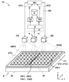
- FIG. 2 is a schematic diagram showing an overall configuration of an example of a form embodying the present invention.
- the first pre-marking pattern PM1 and the second pre-marking pattern PM2 defined in advance toward the workpiece W are marked, the respective marking positions are imaged, the respective positional deviations are corrected, and the workpiece W is corrected.
- a state in which marking is performed by irradiating the workpiece W with a laser beam based on information of the marking pattern PT defined in advance is shown.
- the workpiece W can be exemplified by a transparent PET resin as a base material and a copper foil layer formed on the base material.
- the copper foil layer is removed. That is, a portion remaining after laser irradiation with a predetermined pattern functions as a copper wiring on the substrate.
- FIG. 2 shows a state in which pre-marking, imaging, and marking are performed while the workpiece W is stationary at the second marking position PO2.
- the marking device 1A performs laser marking on the workpiece W using the first marking unit 3A based on the information of the first marking pattern PT1 defined in advance, and the second marking defined in advance. Laser marking is performed using the second marking unit 3B based on the information of the pattern PT2.
- the information of the first marking pattern PT1 and the information of the second marking pattern PT2 are generated in advance based on the information of the marking pattern PT and the information such as the spot diameter of each marking of the first marking unit 3A and the second marking unit 3B.
- a desired marking pattern PT is formed on the workpiece W by superposing and marking the first marking pattern PT1 and the second marking pattern PT2. That is, a portion that is not removed by the first marking pattern PT1 and is not removed by the second marking pattern PT2 remains on the substrate as a copper wiring pattern.
- the marking device 1A includes a workpiece holding and conveying unit 2, a first marking unit 3A, a second marking unit 3B, a pre-marking pattern imaging unit 4, a pre-marking position detecting unit 5, and a pre-marking reference position.
- the registration unit 6 includes a first marking position deviation correction calculation unit 7A, a second marking position deviation correction calculation unit 7B, and a marking controller MC.
- the workpiece holding / conveying unit 2 holds and conveys the workpiece W.
- the work holding and conveying unit 2 includes a table 20 and a table driving unit 25.
- the table 20 has a flat surface (that is, an upper surface) in contact with the workpiece W, and is provided with pores and fine grooves in a part in contact with the workpiece W. These pores and narrow grooves are connected to external negative pressure generating means via a switching valve or the like.
- This negative pressure generating means is for generating a negative pressure in the pores and narrow grooves of the table 20 on which the workpiece W is placed, and examples thereof include a vacuum pump and an ejector. Since the table 20 has such a configuration, the workpiece W that is a marking object can be held in a flat state.
- the table 20 is not limited to the structure having the above-described pores and narrow grooves, and may be configured to be able to suck the workpiece W under a negative pressure using a porous material.
- the table drive unit 25 moves the table 20 in the X direction and stops it.
- the table driving unit 25 can be exemplified by a combination of an electric actuator, a pneumatic cylinder, and a hydraulic cylinder.
- the table driving unit 25 includes a rail extending in the X direction and an X-axis slider that moves on the rail in a predetermined direction and speed and stops at a predetermined location.
- the X-axis slider controls the motor based on a control signal from the outside, or switches the pressure valve based on the control signal from the outside. It can be moved to a third marking position PO1 to PO3) and stopped.
- the first marking unit 3A performs marking with a first spot diameter toward the workpiece W. Specifically, the first marking unit 3A performs a predetermined position in the first marking area MR1, which is an area defined on the workpiece W, based on the marking information of the first marking pattern PT1 defined in advance. Marking a predetermined character or figure, a predetermined pattern, or the like. Further, the first marking unit 3A is predetermined with respect to a predetermined position in the first pre-marking area PR1, which is a region defined on the workpiece, based on the marking information of the first pre-marking pattern PM1 defined in advance. The first pre-marking pattern PM1 such as a character, a figure, or a predetermined pattern is also marked.
- the first marking unit 3A includes a laser light source unit called a laser diode or a laser oscillator and a beam scanner unit called a galvano mirror unit.
- the laser light source unit irradiates the laser beam with pulses or continuously based on a control signal from the outside.
- the beam scanner unit controls to change the angle of the galvanometer mirror based on a control signal from the outside.
- the first marking unit 3A has a configuration including an imaging lens and a mechanism for correcting a focal position shift of a beam spot on a marking processing surface called a Z-axis scanner or an F ⁇ lens.
- the first marking unit 3A may be configured to include a beam expander, an attenuator, or the like between the laser light source unit and the beam scanner unit as necessary. At this time, the first marking unit 3A is arranged to face the workpiece W via an apparatus frame (not shown) or the like.
- the first marking unit 3A marks the workpiece W with the first marking pattern PT1 and the first pre-marking pattern PM1 with a first spot diameter (for example, larger than a second spot diameter described later). It is set to be.
- the second marking unit 3B performs marking with a second spot diameter (in this case, smaller than the first spot diameter) different from the first spot diameter toward the workpiece W.
- the first marking unit 3A marks a large area marking area in a shorter time
- the second marking unit 3B finely marks a minute pattern that could not be marked by the first marking unit 3B. To do.
- the second marking unit 3B is based on information on the second marking pattern PT2 defined in advance with respect to a predetermined position in the second marking area MR2 that is a region defined on the workpiece W. Marks predetermined characters, figures, predetermined patterns, and the like. Further, the second marking unit 3B is predetermined with respect to a predetermined position in the second pre-marking area PR2, which is an area defined on the workpiece, based on the marking information of the second pre-marking pattern PM2 defined in advance.
- the second pre-marking pattern PM2 such as a character, a figure, or a predetermined pattern is also marked.
- the second marking unit 3B is basically the same as the first marking unit 3A in terms of a spot diameter configuration (for example, laser oscillator output, transmission frequency, irradiation pulse frequency, beam expander lens position, curvature, Detailed descriptions are omitted except for the aperture, the size of the galvanometer mirror, the position / curvature / aperture of the F ⁇ lens, the position / curvature of the imaging lens, and the like.
- a spot diameter configuration for example, laser oscillator output, transmission frequency, irradiation pulse frequency, beam expander lens position, curvature, Detailed descriptions are omitted except for the aperture, the size of the galvanometer mirror, the position / curvature / aperture of the F ⁇ lens, the position / curvature of the imaging lens, and the like.
- the first spot diameter is set large and the second spot diameter is set small.
- the reverse state may be set.
- the pre-marking pattern imaging unit 4 images the first pre-marking pattern PM1 and the second pre-marking pattern PM2.
- the pre-marking pattern imaging unit 4 includes an imaging camera 41, a lens (not shown), and observation illumination (not shown).
- the pre-marking pattern imaging unit 4 is configured to capture images of the first pre-marking area PR1 and the second pre-marking area PR2, which are areas defined on the workpiece W, and peripheral portions thereof.
- the imaging camera 41 can output a video signal and video data corresponding to the captured image to an external device.
- the first pre-marking pattern PM1 is marked with the marking reference position PF1 of the first pre-marking pattern registered in the pre-marking reference position registration unit 6 described later as a target.
- the second pre-marking pattern PM2 is marked with the marking reference position PF2 of the second pre-marking pattern registered in the pre-marking reference position registration unit 6 described later as a target.
- the pre-marking position detector 5 detects the marking positions of the first pre-marking pattern PM1 and the second pre-marking pattern PM2.
- the pre-marking position detection unit 5 can be configured by a part of the image processing unit IM.
- the image processing unit IM includes a combination of a computer and an image processing board, hardware called an image processing unit, and an execution program (that is, software).
- the image processing unit IM includes an image input unit VI.
- the image input unit VI is connected to the imaging camera 41 of the pre-marking pattern imaging unit 4, and a video signal corresponding to an image output from the imaging camera 41. And data can be entered.
- the pre-marking position detection unit 5 performs processing for detecting the marking positions of the first pre-marking pattern PM1 and the second pre-marking pattern PM2 based on the video signal and data input to the image input unit VI.
- the pre-marking reference position registration unit 6 registers the marking reference positions of the first pre-marking pattern PM1 and the second pre-marking pattern PM2.
- the pre-marking reference position registration unit 6 can be configured by the memory unit of the image processing unit IM described above.
- Examples of the memory unit of the image processing unit IM include a semiconductor recording medium such as a flash memory and an EEPROM, and a magnetic recording medium such as a hard disk.
- the first marking position deviation correction calculation unit 7A compares the detection result of the marking position of the first pre-marking pattern PM1 with the marking reference position PF1 of the first pre-marking pattern, and the position deviation of the first pre-marking pattern PM1 A quantity correction calculation is performed.
- the first marking position deviation correction calculation unit 7A can be configured by a part of the above-described image processing unit IM.
- the second marking position deviation correction calculation unit 7B compares the detection result of the marking position of the second pre-marking pattern PM2 with the marking reference position PF2 of the second pre-marking pattern to determine the position deviation of the second pre-marking pattern PM2. A quantity correction calculation is performed.
- the second marking position deviation correction calculation unit 7B can be configured by a part of the above-described image processing unit IM.
- the marking controller MC is connected to the first marking unit 3A and the second marking unit 3B, and issues a marking command to these units. Specifically, a command is issued so that marking is performed at a predetermined position on the workpiece W based on the position information of the table 20 conveyed by the workpiece holding and conveying unit 2 (that is, the position information of the workpiece W). Yes. More specifically, the marking controller MC is connected to the first marking misregistration correction calculation unit 7A and the second marking misregistration correction calculation unit 7B, and the misregistration correction amount calculated by the correction calculation units 7A and 7B. The marking position is instructed to the first marking unit 3A and the second marking unit 3B.
- the first marking pattern PT1 and the second marking pattern PT2 described above are registered in the marking controller MC main body or an information recording medium (memory, hard disk, etc.) connected thereto. Alternatively, it may be registered in a main body such as another computer connected to the marking controller MC or an information recording medium (memory, hard disk, etc.) connected thereto, and data may be transmitted to the marking controller MC as appropriate.
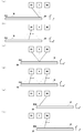
- FIG. 3 is a step diagram showing an operation flow in an example of a form embodying the present invention.
- FIG. 3 shows, for each step, how the marking is performed on the workpiece W using the marking device 1A according to the present invention. That is, each operation is performed in the order of FIGS. 3A, 3B, 3C, 3D, 3E, and 3F.
- the first pre-printing region which is a region defined on the workpiece, based on the marking information of the first pre-marking pattern PM1 defined in advance with the workpiece W at the first marking position PO1.
- a first pre-marking pattern PM1 is irradiated from the first marking unit 3A to a predetermined position in the marking area PR1, and immediately after that, the first pre-marking pattern PM1 marked on the first pre-marking area PR1 is irradiated.
- a state in which the position is imaged by the pre-marking pattern imaging unit 4 is shown.
- FIG. 3B shows a first marking which is a region defined on the workpiece W based on the marking information of the first marking pattern PT1 defined in advance in a state where the workpiece W is at the first marking position PO1.
- a state in which marking is performed on the predetermined position in the area MR1 using the first marking unit 3A is shown.
- the marking unit 3A performs marking at a predetermined position based on the result of the above-described misregistration correction calculation calculated by the first marking misregistration correction calculation unit 7A.
- the first pre-printing region which is a region defined on the workpiece based on the marking information of the first pre-marking pattern PM1 defined in advance with the workpiece W at the second marking position PO2.
- the first pre-marking pattern PM1 is irradiated from the first marking unit 3A to a predetermined position in the marking area PR1, and at the same time, on the workpiece based on the marking information of the second pre-marking pattern PM2 defined in advance.
- the second pre-marking area PR2 is irradiated with the second pre-marking pattern PM2 from the second marking unit 3B to a predetermined position in the second pre-marking area PR2, which is a defined area, and immediately after that, marking the first pre-marking area PR1
- FIG. 3D shows the first marking which is a region defined on the workpiece W based on the marking information of the first marking pattern PT1 defined in advance in a state where the workpiece W is at the second marking position PO2. Marking is performed on the predetermined position in the area MR1 by using the first marking unit 3A. At the same time, the marking is defined on the workpiece W based on the marking information of the second marking pattern PT2 defined in advance. A state is shown in which marking is performed using a second marking unit 3B at a predetermined position in the second marking area MR2, which is an area.
- the marking unit 3A performs marking at a predetermined position based on the result of the above-described misregistration correction calculation calculated by the first marking misregistration correction calculation unit 7A. Further, the marking unit 3B performs marking at a predetermined position based on the result of the above-described misregistration correction calculation calculated by the second marking misregistration correction calculation unit 7B.
- FIG. 3 (e) shows a second pre-prescription that is an area defined on the work based on the pre-defined marking information of the second pre-marking pattern PM2 with the work W at the third marking position PO3.
- the second marking unit 3B, etc. irradiates the second pre-marking pattern PM2 to a predetermined position in the marking area PR2, and immediately after that, the second pre-marking pattern PM2 marked on the second pre-marking area PR2 is irradiated.
- a state in which the position is imaged by the pre-marking pattern imaging unit 4 is shown.
- FIG. 3F shows a second marking that is a region defined on the workpiece W based on the marking information of the second marking pattern PT2 defined in advance in a state where the workpiece W is at the third marking position PO3.
- a state in which marking is performed on the predetermined position in the area MR2 using the second marking unit 3B is shown.
- the marking unit 3B performs marking at a predetermined position based on the result of the above-described misregistration correction calculation calculated by the second marking misregistration correction calculation unit 7B.
- the marking device 1A corrects the amount of positional deviation in advance when marking the workpiece W using the first marking unit and the second marking unit. Marking can be performed. As a result, even if the processing range set for the marking object is wide, high-definition patterning is possible in a short time, and it is possible to prevent the occurrence of misalignment and poor overlay.
- the present invention is not limited to the above-described form, and may be the form shown below.
- the marking device 1B according to the present invention is a modified example of the marking device 1A described above, and does not include the marking controller MC.
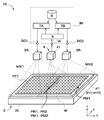
- FIG. 4 is a schematic diagram showing the overall configuration of an example of a form embodying the present invention.
- FIG. 4 shows the overall configuration of the marking device 1B.
- the first marking unit 3A is configured not to use the marking controller MC but to perform marking based on the correction calculation result of the positional deviation amount of the first pre-marking pattern PM1 obtained by the first marking positional deviation correction calculation unit 7A. is doing. Specifically, exchange of the correction calculation result of the positional deviation amount of the first pre-marking pattern PM1 is performed via the data output unit DO1 of the image processing unit IM.
- the second marking unit 3B is configured not to use the marking controller MC, but to perform marking based on the correction calculation result of the positional deviation amount of the second pre-marking pattern PM2 obtained by the second marking positional deviation correction calculation unit 7B. is doing. Specifically, the exchange calculation result of the positional deviation amount of the second pre-marking pattern PM2 is exchanged via the data output unit DO2 of the image processing unit IM.
- the first marking pattern PT1 is registered in advance in the first marking unit 3A
- the second marking pattern PT2 is registered in advance in the second marking unit 3B.
- the first marking pattern PT1 and the second marking pattern PT2 are registered in an information recording medium (such as a memory or a hard disk) or another computer connected to the first marking unit 3A and the second marking unit 3B. May be.
- the marking device 1B corrects the positional deviation amount in advance when marking the workpiece W using the first marking unit 3A and the second marking unit 3B. Marking can be done afterwards. Therefore, even if the processing range set for the marking object is wide, high-definition patterning is possible in a short time, and it is possible to prevent the occurrence of misalignment and poor overlay.
- the marking patterns PT-1 and PT-2 obtained by dividing the marking pattern into two may be defined in advance, and each of the marking patterns may be marked using the first marking unit 3A and the second marking unit 3B.
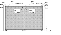
- FIG. 5 is a plan view showing the marking pattern divided into two parts defined in advance with respect to the workpiece and the positional relationship between each marking area.
- marking patterns PT-1 and PT-2, first pre-marking pattern PM1 and second pre-marking pattern PM2, which are defined in advance for the workpiece W, and the workpiece W indicated by a broken line are defined.
- the positional relationships of the first pre-marking area PR1, the second pre-marking area PR2, the marking reference position PF1 of the first pre-marking pattern, and the marking reference position PF2 of the second pre-marking pattern, which are regions, are shown.
- the marking pattern PT-1 is formed by superposing and marking the first marking pattern PT-11 by the first marking unit 3A and the second marking pattern PT-12 by the second marking unit 3B.
- the marking pattern PT-2 is formed by superposing and marking the first marking pattern PT-21 by the first marking unit 3A and the second marking pattern PT-22 by the second marking unit 3B.
- a configuration including a plurality of first marking units and second marking units in the Y direction is used, and a wide range of marking patterns are used for each marking unit.
- it may be in a form of division marking.
- the marking object is not limited to a rectangular shape, and may be a circular shape or other shapes, or may be a form in which marking is performed while intermittently feeding a long sheet. Alternatively, the long sheet may be marked while being continuously fed.
- the workpiece holding / conveying unit 2 is exemplified by the configuration including the table 20 that holds the workpiece W by negative pressure suction and the table driving unit.
- the present invention is not limited to this, and may be embodied by other configurations.
- a configuration using a mechanism called an electrostatic chuck may be used. By doing so, it is possible to apply the present invention not only in the form in which the workpiece W is handled in the atmospheric pressure, but also in the form in which it is handled in the vacuum chamber.
- the workpiece W is preferably held with a flat upper surface like the table 20.
- the workpiece holding and conveying unit 2 is not limited to a form in which the lower surface of the workpiece W is held in close contact with each other, and a mechanism called a grip feeder is used to end the workpiece W. It is good also as a structure conveyed in the workpiece
- the laser marking unit has been described as an example of the first marking unit 3A and the second marking unit 3B.
- a marking unit such as an ink jet method or an exposure transfer method may be provided.
Landscapes
- Physics & Mathematics (AREA)
- Optics & Photonics (AREA)
- Engineering & Computer Science (AREA)
- Plasma & Fusion (AREA)
- Mechanical Engineering (AREA)
- Health & Medical Sciences (AREA)
- General Health & Medical Sciences (AREA)
- Toxicology (AREA)
- General Physics & Mathematics (AREA)
- Laser Beam Processing (AREA)
Abstract
ワーク保持搬送部(2)と、第1マーキングユニット(3A)と、第2マーキングユニット(3B)と、マーキング対象物に設定した第1プリマーキングエリア(PR1)に向けて前記第1マーキングユニット(3A)を用いてマーキングした第1プリマーキングパターン(PM1)及び前記マーキング対象物に設定した第2プリマーキングエリア(PR2)に向けて前記第2マーキングユニット(3B)を用いてマーキングした第2プリマーキングパターン(PM2)を撮像するプリマーキングパターン撮像部(4)と、前記第1プリマーキングパターン(PM1)及び前記第2プリマーキングパターン(PM2)のマーキング位置を検出するプリマーキング位置検出部(5)と、プリマーキング基準位置登録部(6)と、第1マーキング位置ずれ補正計算部(7A)と、第2マーキング位置ずれ補正計算部(7B)とを備えることで、被加工物状に設定した加工範囲が広くても、短時間かつ高精細なパターニングが可能で、位置ずれや重ね合わせ不良の発生を防ぐ。
Description
本発明は、加工対象物に文字や図形、所定パターン等を、マーキング(或いは、パターニング、描画、単に加工とも言う)する、いわゆるマーキング装置に関する。
従来より、レーザ光を2次元方向に走査し、半導体デバイスや液晶ディスプレイ用基板、電子部品などの被加工物上に文字や図形をマーキングするレーザマーキング装置が知られている(例えば、特許文献1)。レーザマーキング装置では、所定のスポット径に設定された状態で、1本のレーザ光を被加工物に照射してマーキングを行っている。
さらに、1台のレーザユニットから放射される1本のパルスレーザ光を、複数の光路に振り分けて加工を行うレーザ加工装置が提案されている(例えば、特許文献2)。
また、レーザ印字をする際にスポット径を小さく変更して、線幅が細くサイズの小さい微小印字が可能なレーザマーキング装置が提案されている(例えば、特許文献3)。
また、薄膜太陽電池のレーザスクライブ装置では、複層の機能膜から構成される加工対象物に対し、各層毎に所定パターンのレーザ加工が行われているが、下層と上層との位置的相関を維持するために、下層パターンのアライメントマークや加工パターンの位置を撮像し、下層パターンの変形や位置ずれ量を考慮し、位置補正して上層にレーザを照射する技術が提案されている(例えば、特許文献4)。
しかし、所定のスポット径に設定された1台のマーキング装置を用いる場合、より微細なパターンを形成するには限界がある。つまり、微細なマーキングパターンに対応すべく、スポット径を小さく設定してしまうと、単位時間あたりに加工できる面積が減少してしまい、微細なパターン描画はできるが、加工時間がかかりすぎてしまう。
また、1つのレーザ光源から複数のレーザ光を複数の光路に振り分けてマーキングしても時間短縮にならず、1つのレーザ光源から照射されるスポット径を変更してマーキングしたとしても、時間短縮には限界がある。
さらに、複数のマーキングユニットを用い、マーキング位置を替えて重ね合わせマーキングを行う形態の場合、個々のマーキングユニットのアライメントが経時的に変化し、位置ずれや、重ね合わせ不良の要因となる。また、先にマーキングされたパターンの位置ずれが著しいと、後でマーキングするパターンが補正しきれず、所望の重ね合わせ精度が維持できなくなる。
そこで、本発明は、マーキング対象物に設定した加工範囲が広くても、短時間かつ高精細なパターニングが可能で、位置ずれや重ね合わせ不良の発生を防ぐ、マーキング装置を提供することを目的とする。
以上の課題を解決するために、本発明に係る形態は、
ワーク保持搬送部と、第1マーキングユニットと、第2マーキングユニットと、プリマーキングパターン撮像部と、プリマーキング位置検出部と、プリマーキング基準位置登録部と、第1マーキング位置ずれ補正計算部と、第2マーキング位置ずれ補正計算部を備えた、マーキング装置である。
ワーク保持搬送部と、第1マーキングユニットと、第2マーキングユニットと、プリマーキングパターン撮像部と、プリマーキング位置検出部と、プリマーキング基準位置登録部と、第1マーキング位置ずれ補正計算部と、第2マーキング位置ずれ補正計算部を備えた、マーキング装置である。
マーキング対象物に設定した加工範囲が広くても、短時間かつ高精細なパターニングが可能で、位置ずれや重ね合わせ不良の発生を防ぐことができる。
以下に、本発明を実施するための具体的な形態について、図を用いながら説明する。
以下の説明では、マーキング対象物の一例として、矩形状の樹脂材料を例示する(以下、単にワークWと呼ぶ)。なお、各図においては、直交座標系の3軸をX、Y、Zとし、XY平面を水平面、Z方向を鉛直方向とする。X方向は、矢印の方向をワーク搬送方向と表現する。Z方向は、矢印の方向を上とし、その逆方向を下と表現する。
以下の説明では、マーキング対象物の一例として、矩形状の樹脂材料を例示する(以下、単にワークWと呼ぶ)。なお、各図においては、直交座標系の3軸をX、Y、Zとし、XY平面を水平面、Z方向を鉛直方向とする。X方向は、矢印の方向をワーク搬送方向と表現する。Z方向は、矢印の方向を上とし、その逆方向を下と表現する。
図1は、ワークに対して予め規定された各マーキングパターンと、各マーキングエリアと位置関係を示す平面図である。
図1には、ワークWに対して予め規定されたマーキングパターンPT、第1プリマーキングパターンPM1及び第2プリマーキングパターンPM2、並びに、破線で示すワークW上に規定された領域である第1プリマーキングエリアPR1、第2プリマーキングエリアPR2、第1プリマーキングパターンのマーキング基準位置PF1及び第2プリマーキングパターンのマーキング基準位置PF2の位置関係が、それぞれ示されている。なお、ここでは、1つのワークW上に、2つの同じマーキングパターンPTをマーキングする形態について示されている。また、この2つの同じマーキングパターンPTは、2つのマーキングパターンPT1,PT2を重ね合わせマーキングすることで形成される。
図1には、ワークWに対して予め規定されたマーキングパターンPT、第1プリマーキングパターンPM1及び第2プリマーキングパターンPM2、並びに、破線で示すワークW上に規定された領域である第1プリマーキングエリアPR1、第2プリマーキングエリアPR2、第1プリマーキングパターンのマーキング基準位置PF1及び第2プリマーキングパターンのマーキング基準位置PF2の位置関係が、それぞれ示されている。なお、ここでは、1つのワークW上に、2つの同じマーキングパターンPTをマーキングする形態について示されている。また、この2つの同じマーキングパターンPTは、2つのマーキングパターンPT1,PT2を重ね合わせマーキングすることで形成される。
図2は、本発明を具現化する形態の一例の全体構成を示す概略図である。
図2には、ワークWに向けて予め規定された第1プリマーキングパターンPM1及び第2プリマーキングパターンPM2をマーキングし、それぞれのマーキング位置を撮像し、それぞれの位置ずれ補正を行ない、ワークWに対して予め規定されたマーキングパターンPTの情報に基づいて、ワークWに向けてレーザビームを照射することによりマーキングを行う様子が示されている。具体的には、ワークWは、透明なPET樹脂を基材とし、その基材の上に銅箔層が形成されたものが例示できる。このワークWに対してレーザビームを照射することで、銅箔層が除去される。つまり、所定のパターンでレーザ照射された後に残った部分が、基材上の銅配線として機能する。
図2には、ワークWに向けて予め規定された第1プリマーキングパターンPM1及び第2プリマーキングパターンPM2をマーキングし、それぞれのマーキング位置を撮像し、それぞれの位置ずれ補正を行ない、ワークWに対して予め規定されたマーキングパターンPTの情報に基づいて、ワークWに向けてレーザビームを照射することによりマーキングを行う様子が示されている。具体的には、ワークWは、透明なPET樹脂を基材とし、その基材の上に銅箔層が形成されたものが例示できる。このワークWに対してレーザビームを照射することで、銅箔層が除去される。つまり、所定のパターンでレーザ照射された後に残った部分が、基材上の銅配線として機能する。
また、詳細は後述するが、マーキングパターンPTを重ね合わせマーキングするために、ワークWを第1~第3マーキング位置PO1~PO3に移動させて、それぞれの位置でマーキングパターンPT1,PT2をマーキングしている。そして、図2には、ワークWが第2マーキング位置PO2にて静止している状態で、プリマーキング・撮像・マーキングされる様子が示されている。
本発明に係るマーキング装置1Aは、ワークWに対して、予め規定された第1マーキングパターンPT1の情報に基づいて第1マーキングユニット3Aを用いてレーザマーキングを行うと共に、予め規定された第2マーキングパターンPT2の情報に基づいて第2マーキングユニット3Bを用いてレーザマーキングを行うものである。第1マーキングパターンPT1の情報及び第2マーキングパターンPT2の情報は、マーキングパターンPTの情報と、第1マーキングユニット3A及び第2マーキングユニット3Bの各マーキングのスポット径などの情報に基づいて、予め生成されている。そして、第1マーキングパターンPT1及び第2マーキングパターンPT2を重ね合わせマーキングすることで、ワークW上には所望のマーキングパターンPTが形成される。つまり、第1マーキングパターンPT1で除去加工されず、第2マーキングパターンPT2でも除去加工がされなかった部分が、銅配線パターンとして基材上に残る。
本発明に係るマーキング装置1Aは、ワーク保持搬送部2と、第1マーキングユニット3Aと、第2マーキングユニット3Bと、プリマーキングパターン撮像部4と、プリマーキング位置検出部5と、プリマーキング基準位置登録部6と、第1マーキング位置ずれ補正計算部7Aと、第2マーキング位置ずれ補正計算部7Bと、マーキングコントローラMCを備えて構成されている。
ワーク保持搬送部2は、ワークWを保持し搬送させるものである。具体的には、ワーク保持搬送部2は、テーブル20と、テーブル駆動部25を備えて構成されている。
テーブル20は、ワークWと接する面(つまり、上面)が平坦あり、ワークWと接する一部分に細孔や細溝が設けられている。そして、これら細孔や細溝は、切り替えバルブなどを介して、外部の負圧発生手段と接続されている。この負圧発生手段は、ワークWが載置されたテーブル20の細孔や細溝に負圧を発生させるためのものであり、真空ポンプやエジェクタなどが例示できる。テーブル20は、この様な構成をしているため、マーキング対象物であるワークWを、平坦な状態で保持することができる。なお、テーブル20は、上述の細孔や細溝を備えた構造に限らず、多孔質材料を用いてワークWを負圧吸引できる構成しても良い。
テーブル駆動部25は、テーブル20をX方向に移動させ静止させるものである。具体的には、テーブル駆動部25は、電動アクチュエータ、空気圧シリンダや油圧シリンダを組み合わせたものが例示できる。より具体的には、テーブル駆動部25は、X方向に延びるレールと、その上を所定の方向・速度で移動し所定の場所で静止するX軸スライダーとで構成されている。そして、X軸スライダーは、外部からの制御信号に基づいてモータの制御を行うことにより、或いは外部からの制御信号に基づいて圧力バルブを切り替えることにより、所定の場所(例えば、後述する第1~第3マーキング位置PO1~PO3など)に移動させ、静止させることができる。
第1マーキングユニット3Aは、ワークWに向けて第1のスポット径でマーキングを行うものである。具体的には、第1マーキングユニット3Aは、予め規定された第1マーキングパターンPT1のマーキング情報に基づいて、ワークW上に規定された領域である第1マーキングエリアMR1内の所定位置に対して、所定の文字や図形、所定パターン等をマーキングするものである。また、第1マーキングユニット3Aは、予め規定された第1プリマーキングパターンPM1のマーキング情報に基づいて、ワーク上に規定された領域である第1プリマーキングエリアPR1内の所定位置に対して、所定の文字や図形、所定パターン等の第1プリマーキングパターンPM1をマーキングするものでもある。
より具体的には、第1マーキングユニット3Aは、レーザ方式の場合、レーザダイオードやレーザ発振器と呼ばれるレーザ光源部と、ガルバノミラーユニットと呼ばれるビームスキャナ部とを備えて構成されている。レーザ光源部は、外部からの制御信号に基づいてレーザ光線をパルス照射又は連続照射するものである。ビームスキャナ部は、外部からの制御信号に基づいて、ガルバノミラーの角度を変更制御するものである。なお、第1マーキングユニット3Aは、上記構成の他、結像レンズと、Z軸スキャナ又はFθレンズと呼ばれるマーキング加工面でのビームスポットの焦点位置ズレを補正する機構を備えた構成としておく。また、第1マーキングユニット3Aは、必要に応じて、レーザ光源部とビームスキャナ部との間に、ビームエキスパンダやアッテネータなどを備えた構成としても良い。このとき、第1マーキングユニット3Aは、装置フレーム(図示せず)等を介してワークWと対向配置させている。
なお、第1マーキングユニット3Aは、第1のスポット径(例えば、後述する第2のスポット径よりも大きい)で、ワークWに対して、第1マーキングパターンPT1と第1プリマーキングパターンPM1をマーキングするように設定されている。
第2マーキングユニット3Bは、ワークWに向けて第1のスポット径とは異なる第2のスポット径(ここでは、第1のスポット径よりも小さい)でマーキングを行うものである。つまり、第1マーキングユニット3Aは、大面積のマーキング領域をより短い時間内でマーキングするのに対し、第2マーキングユニット3Bは、第1マーキングユニット3Bでマーキングできなかった微小なパターンを緻密にマーキングするものである。
具体的には、第2マーキングユニット3Bは、予め規定された第2マーキングパターンPT2の情報に基づいて、ワークW上に規定された領域である第2マーキングエリアMR2内の所定位置に対して、所定の文字や図形、所定パターン等をマーキングするものである。また、第2マーキングユニット3Bは、予め規定された第2プリマーキングパターンPM2のマーキング情報に基づいて、ワーク上に規定された領域である第2プリマーキングエリアPR2内の所定位置に対して、所定の文字や図形、所定パターン等の第2プリマーキングパターンPM2をマーキングするものでもある。
なお、第2マーキングユニット3Bは、第1マーキングユニット3Aと基本的な構成は、スポット径に関する構成(例えば、レーザ発振器の出力・発信周波数・照射パルスの周波数、ビームエキスパンダのレンズ位置・曲率・口径、ガルバノミラーの大きさ、Fθレンズの位置・曲率・口径、結像レンズの位置・曲率など)以外は同じであるため詳細な説明を省略する。
また、上述では、第1のスポット径を大きく、第2のスポット径を小さく設定する形態を例示したが、逆の状態に設定しても良い。
プリマーキングパターン撮像部4は、第1プリマーキングパターンPM1及び第2プリマーキングパターンPM2を撮像するものである。具体的には、プリマーキングパターン撮像部4は、撮像カメラ41と、レンズ(図示せず)と、観察用照明(図示せず)とを備えて構成されている。また、プリマーキングパターン撮像部4は、ワークW上に規定された領域である第1プリマーキングエリアPR1及び第2プリマーキングエリアPR2、並びに、その周辺部の画像を撮像するように構成されている。そして、この撮像カメラ41は、撮像した画像に対応した映像信号や映像データを外部機器へ出力することができる。
なお、第1プリマーキングパターンPM1は、後述するプリマーキング基準位置登録部6に登録された、第1プリマーキングパターンのマーキング基準位置PF1を目標にマーキングされるものである。また、第2プリマーキングパターンPM2は、後述するプリマーキング基準位置登録部6に登録された、第2プリマーキングパターンのマーキング基準位置PF2を目標にマーキングされるものである。
プリマーキング位置検出部5は、第1プリマーキングパターンPM1及び第2プリマーキングパターンPM2のマーキング位置を検出するものである。具体的には、プリマーキング位置検出部5は、画像処理部IMの一部により構成することができる。画像処理部IMは、コンピュータと画像処理ボードを組み合わせたものや画像処理ユニットと呼ばれるハードウェアと、その実行プログラム(つまり、ソフトウェア)により構成されている。画像処理部IMは、画像入力部VIを備え、この画像入力部VIは、プリマーキングパターン撮像部4の撮像カメラ41と接続されており、この撮像カメラ41から出力された画像に対応した映像信号やデータを入力することができる。そして、プリマーキング位置検出部5では、画像入力部VIに入力された映像信号やデータに基づいて、第1プリマーキングパターンPM1及び第2プリマーキングパターンPM2のマーキング位置を検出する処理が行われる。
プリマーキング基準位置登録部6は、第1プリマーキングパターンPM1及び第2プリマーキングパターンPM2のマーキング基準位置を登録するものである。具体的には、プリマーキング基準位置登録部6は、上述の画像処理部IMのメモリー部により構成することができる。この画像処理部IMのメモリー部としては、フラッシュメモリーやEEPROM等の半導体記録媒体の他、ハードディスク等の磁気記録媒体などを例示することができる。
第1マーキング位置ずれ補正計算部7Aは、第1プリマーキングパターンPM1のマーキング位置の検出結果と、第1プリマーキングパターンのマーキング基準位置PF1とを比較して、第1プリマーキングパターンPM1の位置ずれ量の補正計算を行うものである。具体的には、第1マーキング位置ずれ補正計算部7Aは、上述の画像処理部IMの一部により構成することができる。
第2マーキング位置ずれ補正計算部7Bは、第2プリマーキングパターンPM2のマーキング位置の検出結果と、第2プリマーキングパターンのマーキング基準位置PF2とを比較して、第2プリマーキングパターンPM2の位置ずれ量の補正計算を行うものである。具体的には、第2マーキング位置ずれ補正計算部7Bは、上述の画像処理部IMの一部により構成することができる。
マーキングコントローラMCは、第1マーキングユニット3A及び第2マーキングユニット3Bと接続されており、これらのユニットに対してマーキング指令を行うものである。具体的には、ワーク保持搬送部2で搬送されるテーブル20の位置情報(つまり、ワークWの位置情報)に基づいて、ワークW上の所定の位置にマーキングが行われるよう、指令を行っている。より具体的には、マーキングコントローラMCは、第1マーキング位置ずれ補正計算部7A及び第2マーキング位置ずれ補正計算部7Bと接続されており、これら補正計算部7A,7Bで計算した位置ずれ補正量を加減して、第1マーキングユニット3A及び第2マーキングユニット3Bに対してマーキング位置の指令を行っている。
なお、上述の第1マーキングパターンPT1及び第2マーキングパターンPT2は、マーキングコントローラMC本体又はこれに接続された情報記録媒体(メモリーやハードディスクなど)に登録しておく。或いは、マーキングコントローラMCと接続された他のコンピュータ等の本体又はこれに接続された情報記録媒体(メモリーやハードディスクなど)に登録しておき、適宜マーキングコントローラMCにデータを送信しても良い。
[マーキング動作フロー]
図3は、本発明を具現化する形態の一例における動作フローを示すステップ図である。図3には、本発明に係るマーキング装置1Aを用いて、ワークWにマーキングを行う様子が、ステップ毎に示されている。つまり、図3(a)、(b)、(c)、(d)、(e)、(f)の順で各動作が行われる。
図3は、本発明を具現化する形態の一例における動作フローを示すステップ図である。図3には、本発明に係るマーキング装置1Aを用いて、ワークWにマーキングを行う様子が、ステップ毎に示されている。つまり、図3(a)、(b)、(c)、(d)、(e)、(f)の順で各動作が行われる。
図3(a)には、ワークWが第1マーキング位置PO1にある状態で、予め規定された第1プリマーキングパターンPM1のマーキング情報に基づいて、ワーク上に規定された領域である第1プリマーキングエリアPR1内の所定位置に対して、第1マーキングユニット3Aから、第1プリマーキングパターンPM1が照射され、その直後に、当該第1プリマーキングエリアPR1にマーキングされた第1プリマーキングパターンPM1の位置を、プリマーキングパターン撮像部4で撮像している様子が示されている。
図3(b)には、ワークWが第1マーキング位置PO1にある状態で、予め規定された第1マーキングパターンPT1のマーキング情報に基づいて、ワークW上に規定された領域である第1マーキングエリアMR1内の所定位置に対して、第1マーキングユニット3Aを用いてマーキングが行われている様子が示されている。このとき、マーキングユニット3Aは、第1マーキング位置ずれ補正計算部7Aで計算された上述の位置ずれ補正計算の結果に基づいて、予め規定された位置にマーキングを行う。
図3(c)には、ワークWが第2マーキング位置PO2にある状態で、予め規定された第1プリマーキングパターンPM1のマーキング情報に基づいて、ワーク上に規定された領域である第1プリマーキングエリアPR1内の所定位置に対して、第1マーキングユニット3Aから、第1プリマーキングパターンPM1が照射され、同時に、予め規定された第2プリマーキングパターンPM2のマーキング情報に基づいて、ワーク上に規定された領域である第2プリマーキングエリアPR2内の所定位置に対して、第2マーキングユニット3Bら、第2プリマーキングパターンPM2が照射され、その直後に、当該第1プリマーキングエリアPR1にマーキングされた第1プリマーキングパターンPM1の位置と、当該第2プリマーキングエリアPR2にマーキングされた第2プリマーキングパターンPM2の位置とを、プリマーキングパターン撮像部4で撮像している様子が示されている。
図3(d)には、ワークWが第2マーキング位置PO2にある状態で、予め規定された第1マーキングパターンPT1のマーキング情報に基づいて、ワークW上に規定された領域である第1マーキングエリアMR1内の所定位置に対して、第1マーキングユニット3Aを用いてマーキングが行われており、同時に、予め規定された第2マーキングパターンPT2のマーキング情報に基づいて、ワークW上に規定された領域である第2マーキングエリアMR2内の所定位置に対して、第2マーキングユニット3Bを用いてマーキングが行われている様子が示されている。このとき、マーキングユニット3Aは、第1マーキング位置ずれ補正計算部7Aで計算された上述の位置ずれ補正計算の結果に基づいて、予め規定された位置にマーキングを行う。さらに、マーキングユニット3Bは、第2マーキング位置ずれ補正計算部7Bで計算された上述の位置ずれ補正計算の結果に基づいて、予め規定された位置にマーキングを行う。
なお、図3(c)(d)に示す第2マーキング位置における撮像及びマーキングの様子は、図2に示した状態に対応している。
図3(e)には、ワークWが第3マーキング位置PO3にある状態で、予め規定された第2プリマーキングパターンPM2のマーキング情報に基づいて、ワーク上に規定された領域である第2プリマーキングエリアPR2内の所定位置に対して、第2マーキングユニット3Bら、第2プリマーキングパターンPM2が照射され、その直後に、当該第2プリマーキングエリアPR2にマーキングされた第2プリマーキングパターンPM2の位置を、プリマーキングパターン撮像部4で撮像している様子が示されている。
図3(f)には、ワークWが第3マーキング位置PO3にある状態で、予め規定された第2マーキングパターンPT2のマーキング情報に基づいて、ワークW上に規定された領域である第2マーキングエリアMR2内の所定位置に対して、第2マーキングユニット3Bを用いてマーキングが行われている様子が示されている。このとき、マーキングユニット3Bは、第2マーキング位置ずれ補正計算部7Bで計算された上述の位置ずれ補正計算の結果に基づいて、予め規定された位置にマーキングを行う。
この様な構成をしているため、本発明に係るマーキング装置1Aは、第1マーキングユニットと第2マーキングユニットとを用いてワークWに対してマーキングする際、予め位置ずれ量を補正してからマーキングを行うことができる。その結果、マーキング対象物に設定した加工範囲が広くても、短時間かつ高精細なパターニングが可能で、位置ずれや重ね合わせ不良の発生を防ぐことができる。
[他の形態]
本発明を具現化する上で、上述の形態に限定されず、以下に示す形態であっても良い。本発明に係るマーキング装置1Bは、上述したマーキング装置1Aの変形例であり、マーキングコントローラMCを備えていない構成をしている。
本発明を具現化する上で、上述の形態に限定されず、以下に示す形態であっても良い。本発明に係るマーキング装置1Bは、上述したマーキング装置1Aの変形例であり、マーキングコントローラMCを備えていない構成をしている。
図4は、本発明を具現化する形態の一例の全体構成を示す概略図である。図4には、マーキング装置1Bの全体構成が示されている。
第1マーキングユニット3Aは、マーキングコントローラMCを用いずに、第1マーキング位置ずれ補正計算部7Aで得られた第1プリマーキングパターンPM1の位置ずれ量の補正計算結果に基づいてマーキングを行う構成をしている。具体的には、画像処理部IMのデータ出力部DO1を介して、第1プリマーキングパターンPM1の位置ずれ量の補正計算結果のやりとりが行われる。
第2マーキングユニット3Bは、マーキングコントローラMCを用いずに、第2マーキング位置ずれ補正計算部7Bで得られた第2プリマーキングパターンPM2の位置ずれ量の補正計算結果に基づいてマーキングを行う構成をしている。具体的には、画像処理部IMのデータ出力部DO2を介して、第2プリマーキングパターンPM2の位置ずれ量の補正計算結果のやりとりが行われる。
なお、この形態の場合、第1マーキングパターンPT1は、第1マーキングユニット3Aに予め登録しておき、第2マーキングパターンPT2は、第2マーキングユニット3Bに予め登録しておく。或いは、第1マーキングパターンPT1及び第2マーキングパターンPT2は、第1マーキングユニット3A及び第2マーキングユニット3Bに接続された、情報記録媒体(メモリーやハードディスクなど)や他のコンピュータ等に登録しておいても良い。
この様な構成をしているため、本発明に係るマーキング装置1Bは、第1マーキングユニット3Aと第2マーキングユニット3Bとを用いてワークWに対してマーキングする際、予め位置ずれ量を補正してからマーキングを行うことができる。そのため、マーキング対象物に設定した加工範囲が広くても、短時間かつ高精細なパターニングが可能で、位置ずれや重ね合わせ不良の発生を防ぐことができる。
[バリエーション形態]
なお、上述では、図1に示す様な、一枚のワークW上に2つの同じマーキングパターンPT1をマーキング形成する形態について説明したが、これに限定されず、1枚のワークW上に1つのマーキングパターンを2分割したマーキングパターンPT-1,PT-2を予め規定し、それぞれを上述の第1マーキングユニット3A及び第2マーキングユニット3Bを用いて、マーキングする形態であっても良い。
なお、上述では、図1に示す様な、一枚のワークW上に2つの同じマーキングパターンPT1をマーキング形成する形態について説明したが、これに限定されず、1枚のワークW上に1つのマーキングパターンを2分割したマーキングパターンPT-1,PT-2を予め規定し、それぞれを上述の第1マーキングユニット3A及び第2マーキングユニット3Bを用いて、マーキングする形態であっても良い。
図5は、ワークに対して予め規定された2分割したマーキングパターンと、各マーキングエリアと位置関係を示す平面図である。図5には、ワークWに対して予め規定されたマーキングパターンPT-1,PT-2、第1プリマーキングパターンPM1及び第2プリマーキングパターンPM2、並びに、破線で示すワークW上に規定された領域である第1プリマーキングエリアPR1、第2プリマーキングエリアPR2、第1プリマーキングパターンのマーキング基準位置PF1及び第2プリマーキングパターンのマーキング基準位置PF2の位置関係が、それぞれ示されている。
この場合、マーキングパターンPT-1は、第1マーキングユニット3Aにより第1マーキングパターンPT-11を、第2マーキングユニット3Bにより第2マーキングパターンPT-12を、それぞれ重ね合わせマーキングすることで形成される。一方、マーキングパターンPT-2は、第1マーキングユニット3Aにより第1マーキングパターンPT-21を、第2マーキングユニット3Bにより第2マーキングパターンPT-22を、それぞれ重ね合わせマーキングすることで形成される。
なお、上述の様にX方向に2分割した構成に限らず、Y方向に複数の第1マーキングユニット及び第2マーキングユニットを備えた構成とし、広い範囲のマーキングパターンを各々のマーキングユニットを用いて、分割マーキングする形態としても良い。
また、上述では、マーキングの一例として、表面に銅箔層が形成された矩形状のPET樹脂材料(ワークW)に対して、不要部分を除去加工する形態を例示して説明した。しかし、本発明を具現化する上では、被加工物は上述以外の例えば金属や紙など、他の材料であっても良い。また、上述の除去加工に限らず、レーザ光により変色や変質をさせる加工形態であっても良い。さらに、マーキング対象物は、矩形状に限定されず、円形や他の形状であっても良いし、長尺シートを間欠送りしながらマーキングする形態であっても良い。或いは、長尺シートを連続送りしながらマーキングする形態であっても良い。
なお、上述では、ワーク保持搬送部2は、ワークWを負圧吸引により保持するテーブル20及びテーブル駆動部を備えた構成を例示した。しかし、これに限定されず、他の構成により具現化しても良い。例えば、静電チャックと呼ばれる機構を用いた構成としても良い。そうすることで、ワークWが大気圧中でハンドリングされる形態のみならず、真空チャンバー中でもハンドリングされる形態であっても、本発明を適用することが得きる。
なお、ワークWが変形しやすい材料・厚みであれば、ワークWをテーブル20の様に上面が平坦なもので保持することが好ましい。しかし、ワークWが変形しにくい材料・厚みであれば、ワーク保持搬送部2は、ワークWの下面を密着保持する形態に限定されず、グリップフィーダと呼ばれる機構を用いて、ワークWの端部(例えば、四隅)を把持しつつ、ワークWX方向へ搬送する構成としても良い。このとき、ワークWが自重でたわまないように、適宜ワークWの外側に向けて張力がはたらく様にしておくことが好ましい。
なお、上述では、第1マーキングユニット3A及び第2マーキングユニット3Bとして、レーザ方式のマーキングユニットを例示して説明した。しかし、本発明を具現化する上では、インクジェット方式や、露光転写方式などマーキングユニットを備えて構成しても良い。
1A マーキング装置
1B マーキング装置
2 ワーク保持搬送部
3A 第1マーキングユニット
3B 第2マーキングユニット
4 プリマーキングパターン撮像部
5 プリマーキング位置検出部
6 プリマーキング基準位置登録部
7A 第1マーキング位置ずれ補正計算部
7B 第2マーキング位置ずれ補正計算部
41 撮像カメラ
PT マーキングパターン
PT1 第1マーキングパターン
PT2 第2マーキングパターン
MR1 第1マーキングエリア
MR2 第2マーキングエリア
PF1 第1プリマーキングパターンのマーキング基準位置
PF2 第2プリマーキングパターンのマーキング基準位置
PM1 第1プリマーキングパターン
PM2 第2プリマーキングパターン
PR1 第1プリマーキングエリア
PR2 第2プリマーキングエリア
MC マーキングコントローラ
IM 画像処理ユニット
VI 画像入力部
PO1 第1マーキング位置
PO2 第2マーキング位置
PO3 第3マーキング位置
1B マーキング装置
2 ワーク保持搬送部
3A 第1マーキングユニット
3B 第2マーキングユニット
4 プリマーキングパターン撮像部
5 プリマーキング位置検出部
6 プリマーキング基準位置登録部
7A 第1マーキング位置ずれ補正計算部
7B 第2マーキング位置ずれ補正計算部
41 撮像カメラ
PT マーキングパターン
PT1 第1マーキングパターン
PT2 第2マーキングパターン
MR1 第1マーキングエリア
MR2 第2マーキングエリア
PF1 第1プリマーキングパターンのマーキング基準位置
PF2 第2プリマーキングパターンのマーキング基準位置
PM1 第1プリマーキングパターン
PM2 第2プリマーキングパターン
PR1 第1プリマーキングエリア
PR2 第2プリマーキングエリア
MC マーキングコントローラ
IM 画像処理ユニット
VI 画像入力部
PO1 第1マーキング位置
PO2 第2マーキング位置
PO3 第3マーキング位置
Claims (5)
- マーキング対象物を保持し搬送させるワーク保持搬送部と、
前記マーキング対象物に向けて第1のスポット径でマーキングを行う第1マーキングユニットと、
前記マーキング対象物に向けて前記第1のスポット径とは異なる第2のスポット径でマーキングを行う第2マーキングユニットと、
前記マーキング対象物に設定した第1プリマーキングエリアに向けて前記第1マーキングユニットを用いてマーキングした第1プリマーキングパターン及び前記マーキング対象物に設定した第2プリマーキングエリアに向けて前記第2マーキングユニットを用いてマーキングした第2プリマーキングパターンを撮像するプリマーキングパターン撮像部と、
前記第1プリマーキングパターン及び前記第2プリマーキングパターンのマーキング位置を検出するプリマーキング位置検出部と、
前記第1プリマーキングパターン及び前記第2プリマーキングパターンのマーキング基準位置を登録するプリマーキング基準位置登録部と、
前記第1プリマーキングパターンのマーキング位置の検出結果と前記第1プリマーキングパターンのマーキング基準位置とを比較して当該第1プリマーキングパターンの位置ずれ量の補正計算を行う、第1マーキング位置ずれ補正計算部と、
前記第2プリマーキングパターンのマーキング位置の検出結果と前記第2プリマーキングパターンのマーキング基準位置とを比較して当該第2プリマーキングパターンの位置ずれ量の補正計算を行う、第2マーキング位置ずれ補正計算部を備えた、
マーキング装置。 - 前記第1マーキングユニットは、前記第1マーキング位置ずれ補正計算部で得られた前記第1プリマーキングパターンの位置ずれ量の補正計算結果に基づいてマーキングを行い、
前記第2マーキングユニットは、前記第2マーキング位置ずれ補正計算部で得られた前記第2プリマーキングパターンの位置ずれ量の補正計算結果に基づいてマーキングを行う
ことを特徴とする、請求項1に記載のマーキング装置。 - 前記第1マーキングユニット及び前記第2マーキングユニットが、レーザ方式のマーキングユニットであることを特徴とする、請求項1又は請求項2に記載のマーキング装置。
- 前記第1マーキングユニット及び前記第2マーキングユニットが、インクジェット方式のマーキングユニットであることを特徴とする、請求項1又は請求項2に記載のマーキング装置。
- 前記第1マーキングユニット及び前記第2マーキングユニットが、露光転写方式のマーキングユニットであることを特徴とする、請求項1又は請求項2に記載のマーキング装置。
Applications Claiming Priority (2)
| Application Number | Priority Date | Filing Date | Title |
|---|---|---|---|
| JP2014-142810 | 2014-07-11 | ||
| JP2014142810A JP6313148B2 (ja) | 2014-07-11 | 2014-07-11 | マーキング装置 |
Publications (1)
| Publication Number | Publication Date |
|---|---|
| WO2016006587A1 true WO2016006587A1 (ja) | 2016-01-14 |
Family
ID=55064218
Family Applications (1)
| Application Number | Title | Priority Date | Filing Date |
|---|---|---|---|
| PCT/JP2015/069470 Ceased WO2016006587A1 (ja) | 2014-07-11 | 2015-07-07 | マーキング装置 |
Country Status (2)
| Country | Link |
|---|---|
| JP (1) | JP6313148B2 (ja) |
| WO (1) | WO2016006587A1 (ja) |
Cited By (1)
| Publication number | Priority date | Publication date | Assignee | Title |
|---|---|---|---|---|
| WO2024234586A1 (zh) * | 2023-05-17 | 2024-11-21 | 上海博动医疗科技股份有限公司 | 血管图像校正方法、装置、系统和介质 |
Families Citing this family (1)
| Publication number | Priority date | Publication date | Assignee | Title |
|---|---|---|---|---|
| JP7600754B2 (ja) * | 2021-02-26 | 2024-12-17 | 株式会社リコー | レーザ照射装置、レーザ照射方法 |
Citations (6)
| Publication number | Priority date | Publication date | Assignee | Title |
|---|---|---|---|---|
| JPS5984515A (ja) * | 1982-11-08 | 1984-05-16 | Toshiba Corp | レ−ザ光による半導体基板へのマ−キング方法 |
| JPH0793828A (ja) * | 1993-09-21 | 1995-04-07 | Seiko Epson Corp | 光ディスク原盤露光方法 |
| JP2002316288A (ja) * | 2001-04-23 | 2002-10-29 | Matsushita Electric Ind Co Ltd | レーザ加工におけるレーザ照射位置の補正方法 |
| US20060023011A1 (en) * | 2004-07-30 | 2006-02-02 | Hawkins Gilbert A | Suppression of artifacts in inkjet printing |
| JP2007144400A (ja) * | 2005-10-28 | 2007-06-14 | Seiko Epson Corp | パターン形成方法及び液滴吐出装置 |
| JP2012245791A (ja) * | 2009-08-21 | 2012-12-13 | Mimaki Engineering Co Ltd | インクジェットプリンタおよびインクジェット印刷方法 |
-
2014
- 2014-07-11 JP JP2014142810A patent/JP6313148B2/ja not_active Expired - Fee Related
-
2015
- 2015-07-07 WO PCT/JP2015/069470 patent/WO2016006587A1/ja not_active Ceased
Patent Citations (6)
| Publication number | Priority date | Publication date | Assignee | Title |
|---|---|---|---|---|
| JPS5984515A (ja) * | 1982-11-08 | 1984-05-16 | Toshiba Corp | レ−ザ光による半導体基板へのマ−キング方法 |
| JPH0793828A (ja) * | 1993-09-21 | 1995-04-07 | Seiko Epson Corp | 光ディスク原盤露光方法 |
| JP2002316288A (ja) * | 2001-04-23 | 2002-10-29 | Matsushita Electric Ind Co Ltd | レーザ加工におけるレーザ照射位置の補正方法 |
| US20060023011A1 (en) * | 2004-07-30 | 2006-02-02 | Hawkins Gilbert A | Suppression of artifacts in inkjet printing |
| JP2007144400A (ja) * | 2005-10-28 | 2007-06-14 | Seiko Epson Corp | パターン形成方法及び液滴吐出装置 |
| JP2012245791A (ja) * | 2009-08-21 | 2012-12-13 | Mimaki Engineering Co Ltd | インクジェットプリンタおよびインクジェット印刷方法 |
Cited By (1)
| Publication number | Priority date | Publication date | Assignee | Title |
|---|---|---|---|---|
| WO2024234586A1 (zh) * | 2023-05-17 | 2024-11-21 | 上海博动医疗科技股份有限公司 | 血管图像校正方法、装置、系统和介质 |
Also Published As
| Publication number | Publication date |
|---|---|
| JP2016016448A (ja) | 2016-02-01 |
| JP6313148B2 (ja) | 2018-04-18 |
Similar Documents
| Publication | Publication Date | Title |
|---|---|---|
| JP6278451B2 (ja) | マーキング装置およびパターン生成装置 | |
| TWI871683B (zh) | 噴墨印表機及用於製造一電子產品的一層的設備 | |
| US9029731B2 (en) | Methods and systems for laser processing continuously moving sheet material | |
| CN101971099B (zh) | 加工多器件板的激光器 | |
| JP5896459B2 (ja) | マーキング装置及び方法 | |
| KR20100107019A (ko) | 면형체의 얼라이먼트 장치, 제조 장치, 면형체의 얼라이먼트 방법 및 제조 방법 | |
| CN114007803A (zh) | 激光加工装置及方法、芯片转印装置及方法 | |
| CN113597356A (zh) | 用于具有移动片材或卷筒的激光加工机器的表征方法及系统 | |
| JP2017113788A (ja) | 光加工装置 | |
| JP6313148B2 (ja) | マーキング装置 | |
| JP2015093300A (ja) | レーザ加工機 | |
| CN108025392B (zh) | 标印装置 | |
| WO2016147977A1 (ja) | 描画装置 | |
| TW201637762A (zh) | 標記裝置及方法、圖案產生裝置、以及被加工物 | |
| JP6723648B2 (ja) | 位置検出装置及び位置検出方法 | |
| JP2004130342A (ja) | 板状体の両面加工装置 | |
| JP4702965B1 (ja) | パターン形成装置 | |
| TWI688487B (zh) | 板處理裝置及板處理方法 | |
| JP4886719B2 (ja) | 加工装置 | |
| CN105216455B (zh) | 一种激光打标装置及打标方法、打标系统 | |
| JP7633045B2 (ja) | 露光方法および露光装置 | |
| JP5253217B2 (ja) | 基板アライメント方法、基板アライメント装置、レーザ加工裝置及びソーラパネル製造方法 | |
| JP2015188027A (ja) | レーザー加工方法 | |
| WO2015177882A1 (ja) | 作業システム | |
| JP2019082373A (ja) | 光学スケール、エンコーダー、ロボット、電子部品搬送装置、プリンターおよびプロジェクター |
Legal Events
| Date | Code | Title | Description |
|---|---|---|---|
| 121 | Ep: the epo has been informed by wipo that ep was designated in this application |
Ref document number: 15818560 Country of ref document: EP Kind code of ref document: A1 |
|
| NENP | Non-entry into the national phase |
Ref country code: DE |
|
| 32PN | Ep: public notification in the ep bulletin as address of the adressee cannot be established |
Free format text: NOTING OF LOSS OF RIGHTS PURSUANT TO RULE 112(1) EPC (EPO FORM 1205A DATED 24.04.2017) |
|
| 122 | Ep: pct application non-entry in european phase |
Ref document number: 15818560 Country of ref document: EP Kind code of ref document: A1 |