WO2016006560A1 - 端末装置、基地局装置、通信システム、通信方法および集積回路 - Google Patents
端末装置、基地局装置、通信システム、通信方法および集積回路 Download PDFInfo
- Publication number
- WO2016006560A1 WO2016006560A1 PCT/JP2015/069343 JP2015069343W WO2016006560A1 WO 2016006560 A1 WO2016006560 A1 WO 2016006560A1 JP 2015069343 W JP2015069343 W JP 2015069343W WO 2016006560 A1 WO2016006560 A1 WO 2016006560A1
- Authority
- WO
- WIPO (PCT)
- Prior art keywords
- frequency
- terminal device
- cell
- information
- transmission
- Prior art date
Links
- 238000004891 communication Methods 0.000 title claims abstract description 135
- 238000000034 method Methods 0.000 title claims abstract description 94
- 238000011156 evaluation Methods 0.000 claims abstract description 8
- 230000002093 peripheral effect Effects 0.000 claims description 6
- 230000005540 biological transmission Effects 0.000 abstract description 176
- 230000006870 function Effects 0.000 description 25
- 238000012545 processing Methods 0.000 description 23
- 230000008859 change Effects 0.000 description 19
- 239000000872 buffer Substances 0.000 description 18
- 238000010586 diagram Methods 0.000 description 8
- 238000005259 measurement Methods 0.000 description 8
- 238000005516 engineering process Methods 0.000 description 7
- 230000008569 process Effects 0.000 description 6
- 238000013468 resource allocation Methods 0.000 description 6
- 230000008054 signal transmission Effects 0.000 description 5
- 239000000470 constituent Substances 0.000 description 3
- 101000741965 Homo sapiens Inactive tyrosine-protein kinase PRAG1 Proteins 0.000 description 2
- 102100038659 Inactive tyrosine-protein kinase PRAG1 Human genes 0.000 description 2
- 238000012937 correction Methods 0.000 description 2
- 238000012544 monitoring process Methods 0.000 description 2
- 230000000737 periodic effect Effects 0.000 description 2
- 238000010187 selection method Methods 0.000 description 2
- 101150096310 SIB1 gene Proteins 0.000 description 1
- 101150039363 SIB2 gene Proteins 0.000 description 1
- 230000002776 aggregation Effects 0.000 description 1
- 238000004220 aggregation Methods 0.000 description 1
- 238000004378 air conditioning Methods 0.000 description 1
- 230000003321 amplification Effects 0.000 description 1
- 230000020411 cell activation Effects 0.000 description 1
- 238000004140 cleaning Methods 0.000 description 1
- 238000004590 computer program Methods 0.000 description 1
- 239000012141 concentrate Substances 0.000 description 1
- 230000009849 deactivation Effects 0.000 description 1
- 238000013461 design Methods 0.000 description 1
- 230000000694 effects Effects 0.000 description 1
- 230000002779 inactivation Effects 0.000 description 1
- 239000004973 liquid crystal related substance Substances 0.000 description 1
- 230000007774 longterm Effects 0.000 description 1
- 238000007726 management method Methods 0.000 description 1
- 239000011159 matrix material Substances 0.000 description 1
- 238000012986 modification Methods 0.000 description 1
- 230000004048 modification Effects 0.000 description 1
- 238000003199 nucleic acid amplification method Methods 0.000 description 1
- 230000003287 optical effect Effects 0.000 description 1
- 239000004065 semiconductor Substances 0.000 description 1
- 238000000926 separation method Methods 0.000 description 1
- 230000011664 signaling Effects 0.000 description 1
- 238000012546 transfer Methods 0.000 description 1
- 238000005406 washing Methods 0.000 description 1
Images


Classifications
-
- H—ELECTRICITY
- H04—ELECTRIC COMMUNICATION TECHNIQUE
- H04W—WIRELESS COMMUNICATION NETWORKS
- H04W36/00—Hand-off or reselection arrangements
- H04W36/24—Reselection being triggered by specific parameters
- H04W36/26—Reselection being triggered by specific parameters by agreed or negotiated communication parameters
-
- H—ELECTRICITY
- H04—ELECTRIC COMMUNICATION TECHNIQUE
- H04W—WIRELESS COMMUNICATION NETWORKS
- H04W36/00—Hand-off or reselection arrangements
- H04W36/08—Reselecting an access point
-
- H—ELECTRICITY
- H04—ELECTRIC COMMUNICATION TECHNIQUE
- H04W—WIRELESS COMMUNICATION NETWORKS
- H04W4/00—Services specially adapted for wireless communication networks; Facilities therefor
- H04W4/70—Services for machine-to-machine communication [M2M] or machine type communication [MTC]
-
- H—ELECTRICITY
- H04—ELECTRIC COMMUNICATION TECHNIQUE
- H04W—WIRELESS COMMUNICATION NETWORKS
- H04W48/00—Access restriction; Network selection; Access point selection
- H04W48/16—Discovering, processing access restriction or access information
-
- H—ELECTRICITY
- H04—ELECTRIC COMMUNICATION TECHNIQUE
- H04W—WIRELESS COMMUNICATION NETWORKS
- H04W48/00—Access restriction; Network selection; Access point selection
- H04W48/20—Selecting an access point
-
- H—ELECTRICITY
- H04—ELECTRIC COMMUNICATION TECHNIQUE
- H04W—WIRELESS COMMUNICATION NETWORKS
- H04W72/00—Local resource management
- H04W72/02—Selection of wireless resources by user or terminal
-
- H—ELECTRICITY
- H04—ELECTRIC COMMUNICATION TECHNIQUE
- H04W—WIRELESS COMMUNICATION NETWORKS
- H04W72/00—Local resource management
- H04W72/04—Wireless resource allocation
- H04W72/044—Wireless resource allocation based on the type of the allocated resource
- H04W72/0453—Resources in frequency domain, e.g. a carrier in FDMA
-
- H—ELECTRICITY
- H04—ELECTRIC COMMUNICATION TECHNIQUE
- H04W—WIRELESS COMMUNICATION NETWORKS
- H04W92/00—Interfaces specially adapted for wireless communication networks
- H04W92/16—Interfaces between hierarchically similar devices
- H04W92/18—Interfaces between hierarchically similar devices between terminal devices
-
- H—ELECTRICITY
- H04—ELECTRIC COMMUNICATION TECHNIQUE
- H04W—WIRELESS COMMUNICATION NETWORKS
- H04W48/00—Access restriction; Network selection; Access point selection
- H04W48/08—Access restriction or access information delivery, e.g. discovery data delivery
- H04W48/12—Access restriction or access information delivery, e.g. discovery data delivery using downlink control channel
-
- H—ELECTRICITY
- H04—ELECTRIC COMMUNICATION TECHNIQUE
- H04W—WIRELESS COMMUNICATION NETWORKS
- H04W76/00—Connection management
- H04W76/10—Connection setup
- H04W76/14—Direct-mode setup
-
- H—ELECTRICITY
- H04—ELECTRIC COMMUNICATION TECHNIQUE
- H04W—WIRELESS COMMUNICATION NETWORKS
- H04W76/00—Connection management
- H04W76/20—Manipulation of established connections
- H04W76/23—Manipulation of direct-mode connections
Definitions
- the present invention relates to a terminal device, a base station device, a communication system, a communication method, and an integrated circuit that can efficiently perform communication procedures related to inter-device communication.
- EUTR has achieved high-speed communication by adopting OFDM (Orthogonal Frequency-Division Multiplexing) communication method and flexible scheduling in predetermined frequency and time units called resource blocks.
- OFDM Orthogonal Frequency-Division Multiplexing
- resource blocks predetermined frequency and time units called resource blocks.
- EUTRA may also be referred to as LTE (Long Term Evolution).
- LTE-A LTE Advanced
- D2D Device to Device
- LTE-Direct LTE-Direct
- Non-Patent Document 1 In D2D, in order to realize a service between proximity terminal devices (Proximity based Services: ProSe), a method for discovering nearby terminal devices (Discovery), or communication between terminal devices directly (Direct communication) A method for making this possible has been studied by 3GPP (Non-Patent Document 1).
- Non-Patent Document 2 only when an idle terminal device interested in MBMS (Multimedia Broadcast and Multicast Service) is camping on a frequency providing an MBMS-related service (MBMS service), the MBMS In the cell reselection procedure, the priority of the frequency providing the service related to the MBMS is made highest so that the service related to the MBMS can be continued. Has been.
- MBMS Multimedia Broadcast and Multicast Service
- Non-Patent Document 3 by using the same technology as Non-Patent Document 2, an idle terminal device interested in D2D can use a frequency (D2D service) that allows D2D transmission and reception in the cell reselection procedure.
- a frequency D2D service
- a method for enabling transmission or reception of a service related to D2D by making the priority of (providable frequency) the highest is described.
- Non-Patent Document 3 When the terminal device in an idle state interested in D2D is interested in transmission or reception of a service related to D2D by using the method of Non-Patent Document 3, a frequency that allows transmission or reception of D2D is given priority. You can choose. However, when there are many terminal devices that are interested in D2D, the terminal devices concentrate on the frequency (cell) where D2D transmission or reception is possible, and the base station device of such frequency (cell) There is a problem of exceeding capacity (overload).
- D2D is performed using uplink resources, particularly in the case of FDD, a priority is not set for a frequency at which D2D can be transmitted or received, and a method of changing the priority of a conventional frequency There is another problem that cannot be applied.
- the present invention provides a technology related to a terminal device, a base station device, a communication system, a communication method, and an integrated circuit that can efficiently perform communication procedures related to inter-device communication.
- the terminal device when interested in direct communication, cannot transmit / receive data related to direct communication at the frequency of the serving cell, and can transmit data related to direct communication at the frequency of the neighboring cell. Judgment is made on whether or not transmission / reception is possible, and evaluation for selecting a neighboring cell is started at the frequency of the neighboring cell that can send and receive data related to direct communication.
- the terminal device is capable of direct communication with the terminal device, which is performed based on the capability information regarding the combination, the frequency of the serving cell, and the frequency of the neighboring cell.
- the terminal device evaluates neighboring cells by regarding the frequency priority of neighboring cells supporting direct communication as the highest priority.
- the terminal device when the terminal device according to another embodiment of the present invention can transmit and receive data related to direct communication at the frequency of the serving cell, the terminal device directly performs communication in the serving cell.
- the terminal device can efficiently perform communication procedures related to inter-device communication.
- the communication method of the terminal device when interested in direct communication, data related to direct communication cannot be transmitted / received at the frequency of the serving cell, and at the frequency of the neighboring cell. Determining whether it is possible to send and receive data related to direct communication; and starting evaluation for selecting a neighboring cell at a frequency of a neighboring cell capable of sending and receiving data related to direct communication. Such determination includes at least a step performed based on the capability information regarding the combination of frequency bands supported by the terminal device, the frequency of the serving cell, and the frequency of the neighboring cell, and direct communication with the terminal device. This is a communication method of a terminal device capable of
- the communication method of the terminal device further includes the step of evaluating the neighboring cell by regarding the frequency priority of the neighboring cell supporting direct communication as the highest.
- the communication method of the terminal device in other embodiment of this invention further includes the step which performs direct communication in a serving cell, when the transmission / reception of the data regarding direct communication is possible at the frequency of a serving cell. .
- the terminal device can be provided with a communication method for efficiently performing communication procedures related to inter-device communication.
- the integrated circuit of the terminal device is not capable of transmitting / receiving data related to direct communication at the frequency of the serving cell and interested in the frequency of the neighboring cell when interested in direct communication. At least one of a function for determining whether data transmission / reception related to direct communication is possible and a function for starting evaluation for selecting a peripheral cell at a frequency of a peripheral cell capable of data transmission / reception related to direct communication. It is an integrated circuit mounted on a terminal device that allows a terminal device to perform one function and enables direct communication with the terminal device.
- the integrated circuit of the terminal device can cause the terminal device to exhibit a function of efficiently performing a communication procedure related to inter-device communication.
- each embodiment is disclosed in terms of a technique related to a terminal device, a base station device, a communication system, a communication method, and an integrated circuit that perform an efficient communication procedure.
- the system is not limited to the communication system used in EUTRA (LTE, LTE-A).
- CDMA code division multiple access
- TDMA time division multiple access
- FDMA frequency division multiple access
- OFDMA orthogonal FDMA
- SC-FDMA single carrier FDMA
- the embodiment of the present invention it is possible to provide a technology related to a terminal device, a base station device, a communication system, a communication method, and an integrated circuit that perform an efficient communication procedure.
- a channel means a medium used for signal transmission / reception
- a physical channel means a physical medium used for signal transmission / reception.
- a physical channel can be used synonymously with a signal.
- a physical channel may be added to a channel type, or its structure or format may be changed or added. However, this does not affect the description of each embodiment of the present invention.
- Radio frames In EUTRA, scheduling of physical channels or physical signals is managed using radio frames.
- One radio frame is 10 ms, and one radio frame is composed of 10 subframes. Further, one subframe is composed of two slots (that is, one subframe is 1 ms, and one slot is 0.5 ms).
- resource blocks are used as a minimum scheduling unit in which physical channels are allocated.
- a resource block is defined by a constant frequency region composed of a set of a plurality of subcarriers (for example, 12 subcarriers) and a region composed of a constant transmission time interval (1 slot) on the frequency axis.
- the synchronization signal (Synchronization Signals) is composed of three types of primary synchronization signals and secondary synchronization signals composed of 31 types of codes arranged alternately in the frequency domain. 504 kinds of cell identifiers (physical cell ID (Physical Cell Identity; PCI)) for identifying the base station apparatus and frame timing for radio synchronization are shown by the combination.
- the terminal device specifies the physical cell ID of the synchronization signal received by the cell search.
- the physical broadcast information channel (PBCH: Physical Broadcast Channel) is transmitted for the purpose of notifying (setting) master control information commonly used by terminal devices in the cell.
- the base station apparatus notifies (transmits) a master information block (MIB) message via a physical broadcast information channel.
- MIB master information block
- Information notified (set) to the terminal device by the master information block message is setting information of a downlink frequency bandwidth, a system frame number, and a physical channel (PHICH) related to Hybrid ARQ.
- the base station apparatus transmits cell common information (broadcast information) other than the master information block, a system information block type 1 (SIB1; System information block Type 1) message in which the subframe position and period are fixedly determined, and a layer 3 message (RRC). Message).
- SIB1 System information block Type 1
- RRC layer 3 message
- the system information message is notified using the physical downlink shared channel in the radio resource indicated by the physical downlink control channel, and the system information block type 2 to type n (SIB2 to SIBn (n is a natural number) depending on the application) ) Respectively.
- a cell global identifier (CGI; Cell Global Identifier) indicating a cell-specific identifier, a tracking area identifier (TAI; Tracking Area Identifier) for managing a paging standby area, random access setting information, transmission timing adjustment information, cell Common radio resource setting information for each, neighboring cell information (Neighboring cell list) of the same frequency (different frequency, different RAT), uplink access restriction information, and the like are notified.
- CGI Cell Global Identifier
- TAI Tracking Area Identifier
- Downlink reference signals are classified into multiple types according to their use.
- cell-specific reference signals are pilot signals transmitted at a predetermined power for each cell, and are downlink reference signals that are periodically repeated in the frequency domain and the time domain based on a predetermined rule. It is.
- the terminal device measures the reception quality for each cell by receiving the cell-specific RS.
- the terminal apparatus also uses the cell-specific RS as a reference signal for demodulation of the physical downlink control channel or the physical downlink shared channel transmitted together with the cell-specific RS.
- a sequence used for the cell-specific RS a sequence that can be identified for each cell is used.
- the downlink reference signal is also used for estimation of downlink propagation path fluctuation.
- a downlink reference signal used for estimation of propagation path fluctuation is referred to as a channel state information reference signal (CSI-RS).
- CSI-RS channel state information reference signal
- downlink reference signals individually set for the terminal device are referred to as UE specific reference signals (URS) and Demodulation Reference Signal (DMRS), and are a physical downlink control channel, an extended physical downlink control channel, or Referenced for channel propagation path compensation processing when demodulating a physical downlink shared channel.
- URS UE specific reference signals
- DMRS Demodulation Reference Signal
- a physical downlink control channel (PDCCH; Physical Downlink Control Channel) is transmitted in several OFDM symbols (for example, 1 to 4 OFDM symbols) from the top of each subframe.
- An extended physical downlink control channel (EPDCCH; Enhanced Physical Downlink Control Channel) is a physical downlink control channel arranged in an OFDM symbol in which the physical downlink shared channel PDSCH is arranged.
- the PDCCH or EPDCCH is used for the purpose of notifying the terminal device of radio resource allocation information according to the scheduling of the base station device and control information for instructing an adjustment amount of increase / decrease of transmission power.
- a physical downlink control channel (PDCCH) it means both physical channels of PDCCH and EPDCCH unless otherwise specified.
- the terminal apparatus Before transmitting / receiving a layer 2 message (MAC-CE (MAC control element)) and a layer 3 message (paging, system information, etc.), the terminal apparatus monitors (monitors) the physical downlink control channel addressed to itself. By receiving the physical downlink control channel addressed to the device, it is necessary to acquire radio resource allocation information called an uplink grant at the time of transmission and a downlink grant (downlink assignment) at the time of reception from the physical downlink control channel. When D2D is supported, the physical downlink control channel can notify the D2D grant.
- the physical downlink control channel may be configured to be transmitted in the area of the resource block that is assigned individually (dedicated) from the base station apparatus to the terminal apparatus, in addition to being transmitted by the OFDM symbol described above. Is possible.
- the physical uplink control channel is a downlink acknowledgment of acknowledgment (ACK / NACK; Acknowledgement / Negative Acknowledgment) or a downlink propagation path (channel state) transmitted on the physical downlink shared channel.
- ACK / NACK downlink acknowledgment of acknowledgment
- channel state downlink propagation path
- CSI Channel State Information
- SR uplink radio resource allocation request
- CSI includes CQI (Channel Quality Indicator), PMI (Precoding Matrix Indicator), PTI (Precoding Type Indicator), and RI (Rank Indicator). Each Indicator may be written as Indication.
- the physical downlink shared channel (PDSCH: Physical Downlink Shared Channel) is used to notify the terminal device of layer 3 messages such as paging and system information in addition to downlink data.
- the radio resource allocation information of the physical downlink shared channel is indicated (notified) by the physical downlink control channel.
- the physical downlink shared channel is transmitted after being arranged in an OFDM symbol other than the OFDM symbol through which the physical downlink control channel is transmitted. That is, the physical downlink shared channel and the physical downlink control channel are time-division multiplexed within one subframe.
- the physical uplink shared channel mainly transmits uplink data and uplink control data, and can include control data such as CSI and ACK / NACK.
- uplink control information is also used to notify the base station apparatus from the terminal apparatus as a layer 2 message and a layer 3 message.
- the radio resource allocation information of the physical uplink shared channel is indicated by the physical downlink control channel.
- the uplink reference signal (uplink reference signal; Uplink Reference Signal (also referred to as uplink pilot signal or uplink pilot channel)) is transmitted from the base station apparatus to the physical uplink control channel PUCCH and / or the physical uplink shared channel PUSCH.
- Demodulation reference signal (DMRS: ⁇ ⁇ Demodulation Reference Signal) used for demodulating the signal
- SRS sounding reference signal
- the sounding reference signal includes a periodic sounding reference signal (Periodic SRS) transmitted periodically and an aperiodic sounding reference signal (Aperiodic SRS) transmitted when instructed by the base station apparatus. .
- the Physical Random Access Channel (PRACH; “Physical Random Access Channel”) is a channel used to notify (set) a preamble sequence and has a guard time.
- the preamble sequence is configured to notify information to the base station apparatus by a plurality of sequences. For example, when 64 types of sequences are prepared, 6-bit information can be indicated to the base station apparatus.
- the physical random access channel is used as an access means for the terminal device to the base station device.
- the terminal apparatus transmits transmission timing adjustment information (timing advance (for timing uplink ()) required for an uplink radio resource request when the physical uplink control channel is not set, or for matching the uplink transmission timing with the reception timing window of the base station apparatus.
- the physical random access channel is used for requesting the base station apparatus (also called Timing Advance; TA). Also, the base station apparatus can request the terminal apparatus to start a random access procedure using the physical downlink control channel.
- the layer 3 message is a message handled in the protocol of the control plane (CP (Control-plane, C-Plane)) exchanged between the terminal device and the RRC (Radio Resource Control) layer of the base station device, and RRC signaling or RRC Can be used interchangeably with message.
- CP Control-plane, C-Plane
- RRC Radio Resource Control
- a protocol for handling user data with respect to the control plane is referred to as a user plane (UP (User-plane, U-Plane)).
- a D2D synchronization signal (D2DSS; D2D Synchronization Signal) and a physical D2D synchronization channel (PD2DSCH; Physical D2D Synchronization Channel) are prepared as physical channels related to D2D.
- the D2D synchronization signal includes two synchronization signals of PD2DSS (Primary D2DSS) and SD2DSS (Secondary D2DSS).
- the physical D2D synchronization channel is transmitted from a terminal device that transmits D2D, and includes control information related to D2D (for example, synchronization ID, resource pool, system bandwidth, TDD subframe setting, etc. regarding the terminal device that transmits), and D2D frame It is considered to be transmitted for the purpose of notifying numbers.
- a terminal device that transmits D2D transmits a scheduling assignment (SA) to a terminal device that receives D2D.
- SA includes at least ID information for identifying the content (type) of D2D, and explicitly or implicitly notifies a radio resource pattern (RPT: Resource Patterns for Transmission) of transmission data corresponding to the ID information.
- RPT Radio Resource Patterns for Transmission
- the use of PUSCH is considered for transmission data related to SA and D2D. That is, a terminal device that receives D2D needs to receive PUSCH and perform decoding.
- PCFICH Physical Control Format Indicator Channel
- PHICH Physical Hybrid ARQ Indicator Channel
- PMCH physical multicast channel
- the communicable range (communication area) of each frequency controlled by the base station apparatus is regarded as a cell.
- the communication area covered by the base station apparatus may have a different width and a different shape for each frequency.
- the area to cover may differ for every frequency.
- a wireless network in which cells having different types of base station apparatuses and different cell radii are mixed in areas of the same frequency or different frequencies to form one communication system is referred to as a heterogeneous network.
- the terminal device is a cell determined that access of the terminal device is not prohibited based on broadcast information notified from the base station device, and the downlink reception quality satisfies a predetermined condition, and as a result By camping on such a cell, a cell for which normal service is permitted may be regarded as an appropriate cell (Suitable cell).
- the non-radio resource control connection state Idle mode (Idle mode), non-communication
- the radio resource control connection is established (connect In the Tid state (Connected mode) and in communication)
- the movement is performed by the handover procedure.
- the terminal device may regard a cell that has not been determined as an appropriate cell by the cell selection (cell reselection) procedure as a cell (restricted cell) in which only some services are permitted. Note that the terminal device can camp even if it is a restricted cell. Some services are, for example, emergency call communication.
- the terminal device When a terminal device is camping on a cell (idle state) or is connected in a certain cell, the terminal device is located in an area where it can communicate with the base station device, that is, within the service area of the cell. It may be determined that it is (in-coverage).
- the base station apparatus manages one or more cells for each frequency.
- One base station apparatus may manage a plurality of cells.
- the cells are classified into a plurality of types according to the size (cell size) of the area communicable with the terminal device. For example, the cell is classified into a macro cell and a small cell.
- a small cell is a cell that generally covers a radius of several meters to several tens of meters.
- the small cell may be classified into a femto cell, a pico cell, a nano cell, or the like depending on the size of the area.
- the cell set to be used for communication with the terminal device among the cells of the base station device is a serving cell (Serving cell),
- a cell that is not used for other communications is referred to as a neighbor cell.
- the D2D includes at least a technology for discovering a nearby terminal device (Discovery) and a technology for a terminal device to directly communicate with one or a plurality of terminal devices (Direct communication (also referred to as communication)). Divided.
- resources (radio resources) and settings (configuration) related to D2D used by the terminal device may be set (controlled) by the base station device. That is, when the terminal apparatus is in a non-radio resource control connection state (idle state), radio resources and settings related to D2D may be notified for each cell by broadcast information, and the terminal apparatus is in a radio resource control connection state (connected) In the state), radio resources and settings related to D2D may be notified by an RRC message. That is, D2D is realized by a terminal device capable of direct communication between terminal devices (D2D coupled, D2D supported) and a base station device capable of controlling resources for direct communication between the terminal devices.
- radio resources for transmitting scheduling assignments are provided to the terminal device from among resource pools (SA resource pools) pooled for SA.
- a terminal device that transmits D2D transmits SA using radio resources (time and frequency) included in the resource pool.
- a terminal device that receives D2D receives SA using radio resources (time and frequency) included in the resource pool.
- radio resources for transmitting transmission data related to D2D are provided to a terminal device from a resource pool (D2D data resource pool) pooled for transmission data related to D2D.
- a terminal apparatus that transmits D2D transmits transmission data related to D2D using radio resources (time and frequency) specified from the resource pool.
- a terminal device that receives D2D receives transmission data related to D2D using radio resources (time and frequency) specified from the resource pool.
- the resource pool may be indicated by frequency information, information indicating a range of allocated resource blocks, information on a frame number or subframe number and offset value where the resource pool is started, and the like.
- a resource pool in which radio resources used for SA are pooled (first resource pool) and a resource pool in which radio resources used for transmission data related to D2D are pooled (second resource pool) are broadcast information. May be set (reserved) in advance by the base station apparatus, may be notified (or notified) individually for each terminal apparatus, may be notified (or notified) from other terminal apparatuses, It may be pre-configured or may be assigned semi-static.
- SIM Subscriber Identity Module
- the SIM may be an IC card provided by hardware or may be provided by software.
- the terminal device notifies the base station device that there is transmission data related to D2D, so that the base station
- a method of allocating transmission resources individually from the device to the terminal device also referred to as Mode 1 or Scheduled
- the terminal device may be notified from broadcast information or a preset (reserved) resource pool.
- a method of selecting and using transmission resources also referred to as Mode 2 or Autonomous may be used.
- Mode 1 is used when the terminal apparatus is located in a range considered to be in the coverage, and Mode 2 is not located in a range where the terminal apparatus is considered to be in the coverage (out-of-coverage).
- This is the mode of Direct Communication used for.
- the terminal device temporarily uses the radio resource selected by the terminal device during the RRC radio resource reconnection procedure even when the radio resource allocated from the base station device is used (that is, Mode 1). There is a case (ie Mode 2).
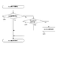
- FIG. 9 is a flowchart illustrating an example in which the terminal apparatus 1-1 (D2D transmission UE) that transmits D2D and the terminal apparatus 1-2 (D2D reception UE) that receives D2D perform D2D communication. is there.
- the terminal apparatus 1-1 when the terminal apparatus 1-1 camps on the cell of the base station apparatus 2, it receives a system information message that is an RRC message (step S100).
- the system information message includes setting information related to D2D (for example, PD2DSS setting information, PD2DSCH setting information, D2D information of neighboring cells, resource pool information for SA, resource pool information for transmission data related to D2D, permission information for Mode1 / Mode2, Etc.) is used for the purpose of notifying the terminal device 1.
- D2D for example, PD2DSS setting information, PD2DSCH setting information, D2D information of neighboring cells, resource pool information for SA, resource pool information for transmission data related to D2D, permission information for Mode1 / Mode2, Etc.
- These pieces of information may be transmitted from the base station apparatus 2 in a certain independent system information block (for example, SIB18). If the terminal apparatus 1-1 (terminal apparatus 1-2) is communicating, individual information may be transmitted. It may be transmitted in an RRC message.
- the terminal apparatus 1-1 performs a cell selection process based on the information of the received system information message (step S101). In this cell selection process, if necessary, the terminal apparatus 1-1 selects a camp cell according to broadcast information indicating whether the RF (Radio Frequency) circuit of the terminal apparatus 1-1 supports D2D in the corresponding uplink band. change.
- RF Radio Frequency
- Step S101 is similarly executed in the terminal device 1-2. That is, if the terminal apparatus 1-2 is interested in D2D, the terminal apparatus 1-2 supports D2D in the uplink band corresponding to the RF (Radio Frequency) circuit of the terminal apparatus 1-2 based on the information of the received system information message. If necessary, cell selection processing is performed according to the broadcast information indicating whether or not.
- RF Radio Frequency
- the terminal device 1-1 starts D2D communication processing (step S102). More specifically, the terminal device 1-1 determines transmission codes and data of PD2DSS and PD2DSCH, and selects a radio resource from a resource pool that can be used for the terminal device 1-1 in an idle state.
- the terminal apparatus 1-1 establishes radio resource control connection (RRC connection establishment, RRC) to the base station apparatus 2 in order to perform D2D in Mode 1.
- RRC connection establishment RRC
- (Connection Establishment) procedure is started and D2D is started in the connected state, which is omitted in the figure.
- the terminal device 1-1 performs PD2DSS transmission (step S103) and PD2DSCH transmission (step S104) using an uplink band (uplink frequency) capable of transmitting D2D. Note that PD2DSCH may not be transmitted.
- the terminal device 1-2 receives the PD2DSS (PD2DSCH) transmitted by the terminal device 1-1 by the D2D synchronization signal processing in step S105, and establishes wireless synchronization with the terminal device 1-1.
- the terminal device 1-1 selects an SA resource from the resources indicated by the SA resource pool information, and transmits the SA using the selected resource to the terminal device 1-2 (step S106). To do. Further, the terminal apparatus 1-1 selects a resource for transmission data from the resource pool information for transmission data based on the selected SA, and uses the selected resource for the terminal apparatus 1-2 to perform data related to D2D. Is transmitted (step S107).
- the terminal device 1-2 receives (monitors) the SA transmitted by the terminal device 1-1 in the resource indicated by the SA resource pool information. Further, the terminal device 1-2 receives (monitors) data related to D2D transmitted by the terminal device 1-1 in the resource indicated by SA in the resource pool information for transmission data.
- FIG. 1 is a block diagram showing an example of a terminal device 1 according to the first embodiment of the present invention.
- the terminal device 1 includes a reception unit 101, a demodulation unit 102, a decoding unit 103, a reception data control unit 104, a physical layer control unit 105, a transmission data control unit 106, a coding unit 107, a modulation unit 108, a transmission unit 109, a radio resource It comprises at least a control unit 110 and a cell selection unit 111.
- the “ ⁇ unit” in the figure is an element that realizes the functions and procedures of the terminal device 1 that are also expressed in terms such as section, circuit, component device, device, and unit.
- the terminal device 1 capable of D2D may be simply abbreviated as the terminal device 1 in some cases.
- the terminal device 1 includes a terminal device 1 that transmits D2D (D2D transmission (terminal device 1-1 in FIG. 9)) and a terminal device 1 that receives D2D (D2D reception (terminal in FIG. 9) in communication related to D2D. It can be any of the devices 1-2)).
- the radio resource control unit 110 executes each function of an RRC (Radio Resource Control) layer that performs radio resource control of the terminal device 1.
- the reception data control unit 104 and the transmission data control unit 106 execute functions in a MAC (Medium Access Control) layer, a RLC (Radio Link Control) layer, and a PDCP (Packet Data Convergence Protocol) layer that manage the data link layer. To do.
- RRC Radio Resource Control
- the reception data control unit 104 and the transmission data control unit 106 execute functions in a MAC (Medium Access Control) layer, a RLC (Radio Link Control) layer, and a PDCP (Packet Data Convergence Protocol) layer that manage the data link layer. To do.
- MAC Medium Access Control
- RLC Radio Link Control
- PDCP Packet Data Convergence Protocol
- the terminal device 1 receives a plurality of frequencies (frequency band, frequency bandwidth) or reception in order to support reception processing and transmission processing in the same subframe of a certain cell in parallel (simultaneously).
- System block reception unit 101, demodulation unit 102, decoding unit 103), a plurality of frequencies (frequency band, frequency bandwidth), and one block of transmission system (encoding unit 107, modulation unit 108, transmission unit 109)
- the structure provided with two or more parts or all may be sufficient.
- reception data control information is input from the radio resource control unit 110 to the reception data control unit 104, and physical layer control information that is a control parameter for controlling each block is input to the physical layer control unit 105. Is entered.
- the physical layer control information is information including parameter settings necessary for wireless communication control of the terminal device 1 configured by reception control information and transmission control information.
- the physical layer control information is set by radio connection resource settings, cell-specific broadcast information, system parameters, or the like transmitted individually (dedicated) from the base station apparatus 2 to the terminal apparatus 1, and the radio resource control unit 110 Input to the physical layer control unit 105 as necessary.
- the physical layer control unit 105 appropriately inputs reception control information that is control information related to reception to the reception unit 101, the demodulation unit 102, and the decoding unit 103.
- the reception control information includes information such as reception frequency band information, reception timing related to physical channels and physical signals, multiplexing method, radio resource control information, SA resource pool information, D2D resource pool information as downlink scheduling information.
- the reception data control information is downlink control information including secondary cell inactivation timer information, DRX control information, multicast data reception information, downlink retransmission control information, SA reception control information, D2D reception control information, and the like.
- Control information regarding each downlink in the MAC layer, the RLC layer, and the PDCP layer is included.
- the received signal is received by the receiving unit 101.
- the received signal may be a transmission signal transmitted by the terminal device 1.
- the receiving unit 101 receives a signal from the base station apparatus 2 according to the frequency and frequency band notified by the reception control information.
- the received signal is input to the demodulation unit 102.
- the demodulator 102 demodulates the signal.
- Demodulation section 102 inputs the demodulated signal to decoding section 103.
- Decoding section 103 decodes the input signal, and inputs the decoded data (also referred to as downlink data, downlink control data, and downlink transport block) to reception data control section 104.
- the MAC control element transmitted from the base station apparatus 2 together with each data is also decoded by the decoding unit 103, and related data is input to the reception data control unit 104.
- the reception data control unit 104 controls the physical layer control unit 105 based on the received MAC control element (for example, cell activation / deactivation, DRX control, transmission timing adjustment, etc.) and buffers each decoded data And error correction control (HARQ) of the retransmitted data. For each data input to the reception data control unit 104, related data is input (transferred) to the radio resource control unit 110.
- the received MAC control element for example, cell activation / deactivation, DRX control, transmission timing adjustment, etc.
- HARQ decoded data And error correction control
- the cell selection unit 111 acquires the received signal and / or channel measurement results (RSRP, RSRQ, etc.) from the output of the demodulation unit 102, the decoding unit 103, etc., and further receives the access restriction information received from the broadcast information, etc. It has a function of performing a cell selection procedure based on a cell selection parameter such as an offset value. In addition, the cell selection unit 111 determines each of the same frequency (Intra-frequency), a different frequency (Inter-frequency), and a different RAT frequency (Inter-RAT) based on the cell reselection parameter related to the cell reselection condition. A function of performing a cell reselection procedure for the neighboring cells.
- RSRP received signal and / or channel measurement results
- RSRQ channel measurement results
- the cell selection unit 111 performs evaluation (assessment, ranking) of neighboring cells by using at least the measurement result of the serving cell currently camping and the measurement result of the neighboring cell.
- the camping cell is changed.
- the cell of the different frequency (RAT) to be measured is determined based on the frequency priority (priority) specified for each frequency (RAT).
- a different frequency (RAT) having a higher priority than the frequency priority of the frequency at which it is camping must always be measured regardless of the measurement result (reception quality) of the serving cell.
- RAT radio access technology
- a cell with a different frequency (RAT) with a priority equal to or lower than the frequency priority of the camping frequency may be measured only when the measurement result of the serving cell is equal to or less than a certain threshold value.
- the measurement result of the serving cell is indicated using, for example, RSRP or RSRQ.
- the cell selection unit 111 can also perform cell reselection using information on neighboring cells when neighboring cell information (neighboring cell list) is notified by broadcast information.
- a plurality of parameters regarding the cell selection procedure and the cell reselection procedure used by the cell selection unit 111 are set from the radio resource control unit 110.
- transmission data control information is input from the radio resource control unit 110 to the transmission data control unit 106, and the physical layer control unit 105 is a physical layer that is a control parameter for controlling each block. Control information is input.
- the physical layer control unit 105 appropriately inputs transmission control information, which is control information related to transmission, to the encoding unit 107, the modulation unit 108, and the transmission unit 109.
- the transmission control information includes, as uplink scheduling information, encoding information, modulation information, transmission frequency band information, transmission timing related to physical channels and physical signals, multiplexing method, radio resource arrangement information, SA resource pool information, D2D resource pool information. Such information is included.
- the transmission data control information includes DTX control information, random access setting information, uplink shared channel information, logical channel priority information, resource request setting information, cell group information, uplink retransmission control information, buffer status report, D2D transmission control.
- the radio resource control unit 110 may set a plurality of random access setting information respectively corresponding to a plurality of cells in the transmission data control unit 106.
- the radio resource control unit 110 manages transmission timing adjustment information and a transmission timing timer used for adjustment of uplink transmission timing, and states of uplink transmission timing (transmission for each cell (or for each cell group and for each TA group)). (Timing adjustment state or transmission timing non-adjustment state).
- the transmission timing adjustment information and the transmission timing timer are included in the transmission data control information.
- the transmission data control unit 106 transmits transmission timing adjustment information corresponding to the uplink transmission timing of each of a plurality of cells (or cell groups, TA groups).
- the resource request setting information includes at least maximum transmission counter setting information and radio resource request prohibition timer information.
- the radio resource control unit 110 may set a plurality of resource request setting information respectively corresponding to a plurality of cells in the transmission data control unit 106.
- Transmission data (uplink data and uplink control data, also referred to as uplink transport block) generated in the terminal device 1 is an upper layer such as a radio resource control unit 110 (or a non-access layer layer unit (not shown)). Input to the transmission data control unit 106 at an arbitrary timing. At this time, the transmission data control unit 106 calculates the amount of input transmission data (uplink buffer amount). The transmission data control unit 106 has a function of determining whether the input transmission data is data belonging to the control plane or data belonging to the user plane.
- the transmission data control unit 106 stores transmission data in an uplink buffer (not shown) in the transmission data control unit 106 when transmission data is input. Also, the transmission data control unit 106 generates a MAC PDU by multiplexing and assembling based on the priority of the transmission data stored in the uplink buffer. Then, the transmission data control unit 106 determines whether radio resources necessary for transmitting the input transmission data are allocated to the terminal device 1. Based on the radio resource allocation, the transmission data control unit 106 receives a radio resource request using a physical uplink shared channel PUSCH, a physical uplink control channel (SR-PUCCH), or a radio resource request using a physical random access channel. Any one is selected, and control processing for transmitting the selected channel is requested to the physical layer control unit 105.
- PUSCH physical uplink shared channel
- SR-PUCCH physical uplink control channel
- the transmission data control unit 106 differs depending on whether the input transmission data is normal transmission data for the base station apparatus 2 or D2D transmission data for another terminal apparatus 1. Generate a buffer status report.
- the transmission data control unit 106 has a buffer status report (normal buffer status report (normal BSR), first buffer status report) based on the buffer amount of normal transmission data, and the buffer amount of D2D transmission data.
- a buffer status report (D2D buffer status report (ProSe BSR), second buffer status report) is generated.
- the encoding unit 107 appropriately encodes each data according to the transmission control information and inputs the data to the modulation unit 108.
- Modulation section 108 performs appropriate modulation processing based on the channel structure for transmitting each encoded data.
- the transmission unit 109 maps each modulated data to the frequency domain, converts the frequency domain signal into a time domain signal, and amplifies the power on a carrier having a predetermined frequency.
- the transmission unit 109 also adjusts the uplink transmission timing according to the transmission timing adjustment information for each cell (also for each cell group and each TA group) input from the radio resource control unit 110.
- the physical uplink shared channel in which the uplink control data is arranged can include, for example, a layer 3 message (radio resource control message; RRC message) in addition to the user data.
- RRC message radio resource control message
- an upper layer of the radio resource control unit 110 includes a non-access stratum (Non Access Stratum) layer unit that performs control with the core network and an application layer unit.
- Non Access Stratum Non Access Stratum
- FIG. 2 is a block diagram showing an example of the base station apparatus 2 according to the first embodiment of the present invention.
- the base station apparatus includes a reception unit 201, a demodulation unit 202, a decoding unit 203, a reception data control unit 204, a physical layer control unit 205, a transmission data control unit 206, a coding unit 207, a modulation unit 208, a transmission unit 209, a radio resource It comprises at least a control unit 210 and a network signal transmission / reception unit 211.
- the “ ⁇ unit” in the figure is an element that realizes the functions and procedures of the base station apparatus 2 that are also expressed in terms such as section, circuit, component device, device, and unit.
- the radio resource control unit 210 executes each function of an RRC (Radio Resource Control) layer that performs radio resource control of the base station apparatus 2.
- RRC Radio Resource Control
- the reception data control unit 204 and the transmission data control unit 206 execute functions in a MAC (Medium Access Control) layer, an RLC (Radio Link Control) layer, and a PDCP (Packet Data Convergence Protocol) layer that manage the data link layer. To do.
- MAC Medium Access Control
- RLC Radio Link Control
- PDCP Packet Data Convergence Protocol
- the base station apparatus 2 uses a reception block (reception unit 201, demodulation) in order to support transmission / reception processing in a plurality of frequencies (frequency bands, frequency bandwidths) or cells within the same subframe by carrier aggregation or the like.
- the radio resource control unit 210 inputs downlink data and downlink control data to the transmission data control unit 206.
- the transmission data control unit 206 inputs the MAC control element and each data (downlink data or downlink control data) to the encoding unit 207.
- the encoding unit 207 encodes the input MAC control element and each data, and inputs the encoded data to the modulation unit 208.
- Modulation section 208 modulates the encoded signal.
- the transmission unit 209 maps the input signal to the frequency domain, converts the frequency domain signal into a time domain signal, and transmits the signal after performing power amplification on a predetermined frequency carrier wave.
- the physical downlink shared channel in which downlink control data is arranged typically constitutes a layer 3 message (RRC message).
- the receiving unit 201 converts the signal received from the terminal device 1 into a baseband digital signal.
- the receiving unit 201 receives signals at different timings for each cell (also for each cell group and each TA group).
- the digital signal converted by the reception unit 201 is input to the demodulation unit 202 and demodulated.
- the signal demodulated by the demodulator 202 is then input to the decoder 203.
- the decoding unit 203 decodes the input signal and inputs each decoded data (uplink data and uplink control data) to the reception data control unit 204.
- the MAC control element transmitted from the terminal device 1 together with each data is also decoded by the decoding unit 203, and related data is input to the reception data control unit 204.
- the received data control unit 204 buffers the physical layer control unit 205 based on the received MAC control element (for example, control related to a power headroom report and control related to a buffer status report) and buffers each decoded data. Then, error correction control (HARQ) of the retransmitted data is performed. Each data input to the reception data control unit 204 is input (transferred) to the radio resource control unit 210 as necessary.
- the received MAC control element for example, control related to a power headroom report and control related to a buffer status report
- HARQ error correction control
- the reception data control unit 204 transmits a transmission resource request for communication with the own base station device or a transmission resource request for inter-device data communication. And a transmission resource to be assigned to the terminal device 1 is set.
- the physical layer control information necessary for control of each block is information including parameter settings necessary for radio communication control of the base station apparatus 2 configured by reception control information and transmission control information.
- the physical layer control information is set by a higher-level network device (MME, gateway device (SGW), OAM, etc.) and system parameters, and the radio resource control unit 210 inputs the control unit 204 as necessary.
- the physical layer control unit 205 inputs physical layer control information related to transmission to each block of the encoding unit 207, modulation unit 208, and transmission unit 209 as transmission control information, and receives physical layer control information related to reception as reception control information. Are appropriately input to each block of the receiving unit 201, the demodulating unit 202, and the decoding unit 203.
- the received data control information includes control information related to the uplink of the terminal device 1 for each of the MAC layer, RLC layer, and PDCP layer of the base station device 2.
- the transmission data control information includes control information related to the downlink of the terminal device 1 for each of the MAC layer, RLC layer, and PDCP layer of the base station device 2. That is, the reception data control information and the transmission data control information are set for each terminal device 1.
- the network signal transmission / reception unit 211 transmits (transfers) or receives a control message or user data between the base station devices 2 or between the upper network device (MME, SGW) and the base station device 2.
- MME mobile phone
- SGW network device
- FIG. 2 the components of other base station apparatus 2 and the transmission path of data (control information) between the components are omitted, but other functions necessary for operating as base station apparatus 2 are omitted. It is clear that it has a plurality of blocks as constituent elements. For example, a radio resource management unit and an application layer unit exist above the radio resource control unit 210.
- FIG. 3 shows an example of a flowchart regarding cell selection (including cell reselection) in the first embodiment of the present invention.
- step S201 the terminal device 1 determines whether or not D2D transmission / reception is possible in the cell that is normally camping.
- the terminal device 1 performs initial camp selection or cell reselection, and normally camps on a certain arbitrary cell (Camped Normal).
- Normal camp means that the cell measurement results satisfy the cell selection criteria (that is, the cell measurement result is greater than a certain value), and the camp and / or normal service is restricted by the access restriction information indicated by the broadcast information.
- the state which the terminal device 1 is located in the area (within a coverage) of no cell is shown.
- step S201 the terminal device 1 determines whether D2D transmission / reception is possible based on the frequency (frequency band) of the camping cell and the frequency at which the terminal device can transmit / receive.
- FIG. 4 is a diagram illustrating an example of a combination of frequency bands (Band Combination) that can be transmitted and received in the terminal device 1 capable of D2D.
- the combination of frequency bands is set for each terminal device 1 as RF capability (RF capability).
- DL # 0 and DL # 1 in the figure indicate downlink frequencies, respectively, and UL # 0 and UL # 1 indicate uplink frequencies, respectively.
- DL # 0 and UL # 0 are some frequencies of Band # 0 which is a certain frequency band
- DL # 1 and UL # 1 are some frequencies of Band # 1 which is another certain frequency band. is there.
- FIG. 4 shows three combinations.
- the RF of the terminal device 1 is tuned to the frequency of DL # 0 and UL # 0 and can be received at the frequency of DL # 0. This indicates that transmission is possible at the frequency of UL # 0.
- D2D when D2D is supported, it indicates that D2D reception (that is, reception of PD2DSS, PD2DSCH, and PUSCH) is possible at the frequency of UL # 0.
- the RF of the terminal device 1 is tuned to the frequencies of DL # 0 and UL # 1, and can be received at the frequency of DL # 0. This indicates that transmission is possible at the frequency of UL # 1. Further, when D2D is supported, it indicates that D2D reception (that is, reception of PD2DSS, PD2DSCH, and PUSCH) is possible at the frequency of UL # 1.
- the RF of the terminal device 1 is tuned to the frequencies of DL # 1 and UL # 1, and can be received at the frequency of DL # 1, This indicates that transmission is possible at the frequency of UL # 1. Further, when D2D is supported, it indicates that D2D reception (that is, reception of PD2DSS, PD2DSCH, and PUSCH) is possible at the frequency of UL # 1.
- the frequency that the terminal device 1 capable of the first combination is normally camping is DL # 0, and the frequency (D2D supported frequency) that supports (permits) D2D transmission / reception is UL # 1.
- the terminal device 1 determines that D2D can be transmitted / received in a state where the terminal device 1 is normally camping on the DL # 0 cell.
- the terminal device 1 determines that D2D cannot be transmitted / received in a state where the terminal device 1 is normally camping on the DL # 0 cell.
- the terminal device 1 supports the combination of the downlink frequency of the cell where the terminal device 1 is currently camping and the uplink frequency that supports D2D transmission / reception by the RF of the terminal device 1. Whether or not there is is determined in step S201.
- the terminal device 1 determines that D2D transmission / reception is possible without changing the current cell (Yes in step S201), and ends the processing of this flow. On the other hand, if it is determined that it is not supported, the terminal device 1 determines that D2D transmission / reception is not possible without changing the current cell (No in step S201).
- step S202 the terminal device 1 determines whether or not frequency priority change in cell selection is permitted.
- the base station apparatus 2 may notify the terminal apparatus 1 for each cell by broadcast information (system information message (SIB18)) whether or not the frequency priority can be changed. You may notify for every terminal device 1 with a RRC message. Alternatively, the terminal device 1 may determine whether or not it is possible to change the frequency priority according to pre-configured in the terminal device itself.
- SIB18 system information message
- the base station apparatus 2 includes, for example, (1) a method for indicating whether or not priority can be changed for each uplink frequency band corresponding to (linked to) a downlink frequency of a certain cell, together with the downlink frequency ( 2) Use a method such as a method for indicating whether or not priority can be changed for each uplink frequency band corresponding to (linked to) the downlink frequency of a cell separately from the downlink frequency. The terminal device 1 is notified whether the change is possible.
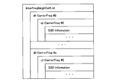
- FIG. 5 and FIG. 6 show examples of data structures of information notified from the base station apparatus 2 to the terminal apparatus 1, respectively.
- FIG. 5 shows an example in which the terminal device 1 is notified of the different frequency neighboring cell list (InterFreqNeighCellList).
- the different frequency neighboring cell list further includes downlink frequency information (dl-CarrierFreq).
- the downlink frequency information further includes uplink frequency information (ul-CarrierFreq) and D2D information (D2D Information).
- the downlink frequency information, the uplink frequency information, and the D2D support information can each include a plurality (# 0 to #n) of information in units of frequencies (or frequency bands).
- the D2D information includes information indicating whether or not D2D is supported by the uplink frequency (ul-CarrierFreq) and / or the frequency priority of the downlink frequency (dl-CarrierFreq) is changed in the cell reselection procedure. Contains information indicating whether or not it is possible. These pieces of information may be shown explicitly or implicitly.
- the change is permitted, “Allowed” is permitted. If not, “Not-Allowed” may be set and notified, or if implicit, “Allowed” is set when the change is permitted, and nothing is notified when the change is not permitted. May be.
- the terminal apparatus 1 supports D2D on the uplink frequency (ul-CarrierFreq) based on the D2D information for a cell having a downlink frequency of dl-CarrierFreq and an uplink frequency of ul-CarrierFreq And / or whether or not the frequency priority of the downlink frequency (dl-CarrierFreq) can be changed in the cell reselection procedure.
- FIG. 6 shows an example in which the terminal device 1 is notified of the uplink frequency neighboring cell list (UL-InterFreqNeighCellList).
- the uplink frequency neighboring cell list further includes uplink frequency information (ul-CarrierFreq) and D2D information (D2D Information).
- Uplink frequency information and D2D support information can include a plurality (# 0 to #n) of information in units of frequencies (or frequency bands).
- the uplink frequency neighboring cell list corresponds to a downlink frequency neighboring cell list that is separately notified to the terminal device 1. That is, the order of the downlink frequencies (dl-CarrierFreq) entered in the downlink frequency neighboring cell list corresponds to the uplink frequencies (ul-CarrierFreq) entered in the uplink frequency neighboring cell list. For example, dl-CarrierFreq # n in the downlink frequency neighboring cell list corresponds (links) to ul-CarrierFreq # n in the uplink frequency neighboring cell list.
- the terminal apparatus 1 supports D2D on the uplink frequency (ul-CarrierFreq) based on the D2D information for a cell having a downlink frequency of dl-CarrierFreq and an uplink frequency of ul-CarrierFreq And / or whether or not the frequency priority of the downlink frequency (dl-CarrierFreq) can be changed in the cell reselection procedure.
- the base station apparatus 2 may not include uplink frequency information (ul-CarrierFreq) in the TDD band. That is, the base station apparatus 2 includes uplink frequency information (ul-CarrierFreq) in addition to D2D information when the frequency included in the different frequency neighboring cell list is the FDD band.
- uplink frequency information ul-CarrierFreq
- the terminal device 1 determines whether or not the change of the frequency priority in the cell reselection procedure is permitted based on the information of the neighboring cell list notified from the base station device 2 in step S202.
- step S202 When it is determined that the change of the frequency priority is permitted (No in step S202), the terminal device 1 determines that D2D transmission / reception is impossible in the current serving cell. On the other hand, when it is determined that the change of the frequency priority is permitted (Yes in step S202), D2D cell selection processing is performed (step S203).
- the terminal device 1 has the highest downlink frequency priority value corresponding to the uplink frequency supporting D2D transmission / reception, regardless of the value notified by the broadcast information (Highest). It is assumed to be a priority value. More specifically, the terminal device 1 regards a value (for example, 8) exceeding the frequency priority value (0 to 7) notified by the broadcast information as the priority of the frequency.
- the frequency at which the terminal device 1 is normally camping is DL # 0
- the frequency (D2D supported frequency) that supports (permits) D2D transmission / reception is UL # 1.
- the RF of the terminal device 1 can be only the first combination and the third combination, it is determined that D2D cannot be transmitted / received in the state where the terminal device 1 is normally camping on the cell of DL # 0.
- the terminal device 1 regards the priority of the frequency of DL # 1 as the highest value. To initiate the cell reselection procedure.
- the base station apparatus 2 may notify the terminal apparatus 1 of a special offset value for cell reselection related to D2D, which is applied only when evaluating a cell having a frequency supporting D2D.
- FIG. 7 shows another example of a flowchart relating to cell selection in the first embodiment of the present invention.
- the terminal device 1 may perform the same processing (determination) in step S301 as the determination of whether or not D2D transmission / reception in step S201 in FIG. 3 is possible. Further, the terminal device 1 may perform the same processing (determination) in step S302 of FIG. 7 as the determination of whether or not the change of the frequency priority in the cell selection in step S202 of FIG. 3 is permitted. . Further, the terminal device 1 may perform the same processing (determination) in step S303 in FIG. 7 as the D2D cell selection processing in step S203 in FIG.
- step S302 determines whether or not the change of the frequency priority is permitted in step S302
- the terminal device 1 determines that the change of the frequency priority is not permitted ( In step S302, No)
- the D2D gap process step S304 is performed.
- the terminal device 1 supports D2D based on the combination of RF that the terminal device 1 can take even when the priority of the frequency (frequency band) supporting D2D is not permitted. If transmission / reception at a frequency is possible, the terminal device 1 may autonomously generate a gap and attempt transmission / reception of D2D at this frequency.
- the terminal device 1 supports the first combination and the third combination as possible combinations of RF. Further, it is assumed that frequency change in cell reselection is not permitted. Assume that the frequency at which the terminal device 1 is normally camping is DL # 0, and the frequency (D2D supported frequency) that supports (permits) D2D transmission / reception is UL # 1.
- the terminal device 1 uses the first combination as a combination of RF. At this time, the terminal device 1 determines that D2D cannot be transmitted / received in a state where the terminal device 1 is normally camping on the DL # 0 cell, and at a timing (D2D gap, idle gap) autonomously determined based on the D2D information of the neighboring cells, The RF is switched from the frequency band Band # 0 to the frequency band Band # 1. That is, the terminal device 1 changes the combination of RF from the first combination to the third combination in order to perform D2D transmission / reception in UL # 1.
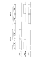
- FIG. 8 is a diagram illustrating that the terminal device 1 performs transmission / reception of a frequency (frequency band) supporting D2D at an autonomous gap timing from a frequency (frequency band) where the terminal device 1 is normally camping.
- the horizontal axis of the figure shows the passage of time, the lower part of the figure shows the operation of the terminal apparatus 1 at the downlink frequency (DL frequency # 0) of the cell in which the terminal apparatus 1 is normally camping, and the upper part of the figure Is different from the uplink frequency (UL frequency # 0 (not shown)) of the cell in which the terminal device 1 is normally camping, and is different from the uplink frequency (UL frequency # 1) of the terminal device 1 that supports D2D.
- the operation is shown.
- the terminal device 1 is in an idle state, and intermittently monitors the transmission signal (PDCCH) from the base station device 2 at a paging reception interval (Paging Period).
- PDCCH transmission signal
- Paging Period paging reception interval
- the terminal device 1 monitors the PDCCH in which the CRC is masked by P-RNTI (Paging-Radio Network Temporary Identity) in the common search area (common search space) at time T0, and tries to receive paging.
- P-RNTI Paging-Radio Network Temporary Identity
- the paging is received in a time length that is required to monitor the PDCCH, which is called an active time.
- the terminal device 1 From the end of the active time until the next attempt to receive paging (time T3), the terminal device 1 regards it as a period during which it is not necessary to perform transmission / reception processing for a cell that is normally camping, and the idle gap (Idle gap) ) Can be generated.
- the terminal device 1 performs D2D transmission / reception on the uplink frequency (UL frequency # 1) in a section (between time T1 and time T2 in the figure) in which a resource pool for SA and D2D data transmission / reception is set. Try.
- the terminal device 1 receives and / or transmits SA in the SA resource pool on the uplink frequency (UL frequency # 1) supporting D2D in the idle gap section, and receives the D2D data resource. Data on D2D is received and / or transmitted in the pool.
- the terminal device 1 may perform only the reception process regarding D2D, when interested only in reception of D2D.
- the terminal device 1 may perform only transmission processing related to D2D.
- the terminal device 1 autonomously determines the gap length of the idle gap.
- the gap length of the idle gap typically only needs to be guaranteed at least as long as the terminal device 1 can receive SA and D2D data related to D2D of interest.
- the SA resource pool and the D2D data resource pool in the figure include a transmission resource pool and a reception resource pool, respectively.
- the resource pool for transmission and the resource pool for reception may be time division multiplexed or frequency multiplexed. Further, even if the set of the SA resource pool for transmission and the D2D data resource pool for transmission, and the set of SA resource pool for reception and D2D data resource pool for reception are time-division multiplexed or frequency multiplexed, Good.
- the processing after time T3 may be repeated from time T0 to time T3 until the terminal apparatus 1 is in the connected state or is in a connected state, or until another cell is selected by cell reselection. .
- the terminal device 1 when the terminal device 1 is authenticated (Authorized) by the network or an external device for (2) transmission / reception of D2D, the terminal device 1 acquires information regarding D2D from the broadcast information of the cell where the terminal device 1 is camping (3) When the start of D2D is notified from an upper layer such as the NAS layer or the application layer, (4) When starting a D2D service having a higher priority than the D2D being executed, (5 ) When the PDCP entity and / or the RLC entity corresponding to D2D are established, it may be considered that the trigger condition is satisfied (the subscription condition is satisfied).
- the terminal device 1 typically determines whether the trigger condition is satisfied before the D2D cell selection process (step S203 in FIG. 3 and step S303 in FIG. 7), but is not limited to this timing. You may judge at the timing of.
- the terminal device 1 may classify the start of D2D as a trigger condition into the start of reception of data related to D2D and the start of transmission of data related to D2D. For example, the terminal device 1 may use only the start of reception of data related to D2D as a trigger condition, and may not use the start of transmission of data related to D2D as a trigger condition, or vice versa.
- the terminal device 1 may use these trigger conditions individually or in combination. There may be a plurality of trigger conditions. Also, which of these trigger conditions is used (or not used) may be notified from the base station device 2 for each cell or each terminal device 1 or may be set in advance. Note that other trigger conditions may be set.
- the terminal device 1 is notified by broadcast information that the cell that is normally camping does not support D2D, or that the cell that is normally camping does not support Mode1 from the base station device 2
- RRC timer related to RRC connection rejection (RRC Connection Reject) in the RRC connection establishment procedure is timed
- the RRC timer related to the restriction of RRC connection establishment is timed
- the individual priority is already set by the base station device 2 If it is necessary to start D2D of Mode2, such as when the RRC timer for the radio resource control connection re-establishment (RRC connection re-establishment, RRC Connection Re-establishment) procedure is timed.
- the Trigger condition or, may be regarded as prerequisites for changing the priority of the frequency.
- the terminal apparatus 1 may start D2D of Mode1 instead of changing the frequency priority value and performing cell reselection.
- the terminal apparatus 1 determines the priority of the related frequency.
- the cell reselection procedure may be performed by changing the value of RRC, or the RRC connection establishment procedure may be started in order to start D2D of Mode1.
- the base station apparatus 2 starts D2D of Mode 1 for the terminal apparatus 1, the base station apparatus 2 can move the terminal apparatus 1 to a cell supporting D2D transmission / reception using a handover procedure.
- the terminal device 1 may start the RRC connection establishment procedure when the terminal device 1 transmits D2D, and may change the frequency priority value when the terminal device 1 receives D2D. Alternatively, the terminal device 1 may change the value of the frequency priority when D2D transmission is not performed.
- the terminal device 1 when the terminal device 1 is not interested in D2D, (2) when shifting to the connected state, (3) when another cell is selected by cell reselection, (4) being executed When starting D2D services with higher priority than D2D, (5) When PDCP entity and / or RLC entity corresponding to D2D is released, (6) Separate for a certain frequency by a separate RRC message When the priority is set, the trigger condition may not be satisfied (the separation condition is satisfied).
- the terminal device 1 may be notified that the D2D is no longer interested from an upper layer such as the NAS layer or the application layer layer.
- the terminal device 1 may be regarded as having lost interest in D2D when a certain period of time has elapsed since the end of D2D transmission / reception.
- the terminal device 1 may determine that the terminal device 1 has shifted to the connected state at the timing when the RRC connection establishment procedure is started or when the timer (T300) related to the RRC connection establishment procedure is started.
- the terminal apparatus 1 when another priority is set (notified) for a certain frequency by an individual RRC message, the terminal apparatus 1 includes a frequency that supports D2D other than the frequency for which the priority is set by the RRC message. All priority values notified by the cell information may be ignored.
- the terminal device 1 may use these trigger conditions individually or in combination. There may be a plurality of trigger conditions. Further, which of these trigger conditions is used or not used may be notified from the base station apparatus 2 for each cell or each terminal apparatus 1 or may be set in advance. Note that other trigger conditions may be set.
- the terminal device 1 when the terminal device 1 is interested in D2D, the terminal device 1 has a combination of RF (RF Capability) implemented in the terminal device, a frequency (frequency band) that supports D2D, and the terminal device 1 itself. Based on the frequency (frequency band) at which the terminal device is camping, it is possible to determine whether transmission / reception at a frequency supporting D2D is possible. In addition, when transmission / reception is not possible at a frequency supporting D2D, the terminal device 1 performs a cell reselection procedure in which the priority of the frequency supporting D2D is changed based on the D2D information notified from the base station device 2. be able to.
- RF RF Capability
- the terminal device 1 supports D2D using an autonomous gap based on neighboring cell information (D2D information) notified from the base station device 2.
- Transmission / reception can be performed at a frequency.
- the base station apparatus 2 can notify the permission of the cell reselection procedure which changed the priority of the frequency which supports D2D with respect to the terminal device 1 by notifying surrounding cell information.
- the terminal device 1 when the terminal device 1 is interested in D2D, as a communication method related to D2D, the terminal device 1 has a frequency that supports D2D based on neighboring cell information (D2D information) from the base station device 2.
- D2D information neighboring cell information
- the base station apparatus 2 permits or disallows a cell reselection procedure in which the priority of the frequency supporting D2D is changed for the terminal apparatus 1 based on the frequency capacity of the own base station apparatus and / or neighboring cells.
- the cell reselection method for setting the priority of the frequency higher than the other frequencies when the terminal device 1 cannot perform transmission / reception of the frequency supporting D2D in the cell where the terminal device 1 is normally camping has been described.
- the terminal device 1 is capable of transmitting and receiving a frequency that supports D2D in a cell that is normally camping, the cell reselection that sets the priority of the frequency higher than other frequencies The method is shown.
- the configurations of the terminal device 1 and the base station device 2 of the second embodiment may be the same as those of the first embodiment, description thereof is omitted.
- the trigger condition used in the second embodiment may be the same as that in the first embodiment.
- the terminal device 1 supports all the first to third combinations as possible combinations of RF. Assume that the frequency at which the terminal device 1 is normally camping is DL # 0, and the frequency (D2D supported frequency) that supports (permits) D2D transmission / reception is UL # 1.
- the base station apparatus 2 notifies the terminal apparatus 1 of a different frequency neighboring cell list (InterFreqNeighCellList) indicating frequencies that support (permit) at least D2D transmission / reception.
- InterFreqNeighCellList a different frequency neighboring cell list
- the terminal apparatus 1 obtains information on frequencies supporting D2D transmission / reception from the different frequency neighboring cell list from the base station apparatus 2, and then uses the second combination to downlink in the DL # 0 cell.
- D2D transmission / reception is performed in UL # 1 while monitoring the link, and / or D2D transmission / reception is performed in UL # 1 while monitoring the downlink in the DL # 1 cell using the third combination. It can be judged that it is possible.
- the terminal apparatus 1 considers both the DL # 0 and DL # 1 frequency priorities as the highest value and starts the cell reselection procedure.
- the terminal device 1 when there are a plurality of RF combinations corresponding to the uplink frequency for which the terminal device 1 supports D2D transmission / reception, the terminal device 1 has the highest frequency priority corresponding to the plurality of RF combinations.
- the cell reselection procedure may be performed by regarding the value.
- a cell reselection procedure in which the priority of the frequency supporting D2D is changed can be performed.
- the terminal device 1 when the terminal device 1 is interested in D2D, the terminal device 1 is based on a combination of RF (RF Capability) implemented in the terminal device and a frequency (frequency band) that supports D2D. Thus, it is possible to determine whether transmission / reception at a frequency supporting D2D is possible. When transmission / reception is possible at a frequency that supports D2D, the terminal device 1 can perform a cell reselection procedure in which the priority of the corresponding frequency is changed in all combinations of RF that can be transmitted / received.
- RF RF Capability
- the base station apparatus 2 notifies the terminal apparatus 1 of permission of the cell reselection procedure by changing the priority of the frequency corresponding to the RF combination by notifying the neighboring cell information (D2D information) of the neighboring cell. can do.
- D2D information neighboring cell information
- the communication method related to D2D is based on the neighboring cell information (D2D information) from the base station device 2, and the RF of the terminal device 1
- D2D information the neighboring cell information
- the base station device 2 permits or disallows the cell reselection procedure in which the priority of the corresponding frequency is changed for the terminal device 1 based on the frequency capacity of the own base station device and / or neighboring cells.
- load balance between frequencies can be adjusted, so that communication corresponding to D2D and communication procedures related to D2D can be performed efficiently.
- the uplink transmission scheme can be applied to both communication systems of the FDD (frequency division duplex) scheme and the TDD (time division duplex) scheme.
- the names of the parameters and events shown in the embodiments are referred to for convenience of explanation, and even if the names actually applied differ from the names of the embodiments of the present invention, It does not affect the gist of the invention claimed in the embodiments of the invention.
- connection used in each embodiment is not limited to a configuration in which a certain device and another certain device are directly connected using a physical line, and is logically connected. And a configuration in which wireless connection is performed using a wireless technology.
- the terminal device 1 is not only a portable or movable mobile station device, but also a stationary or non-movable electronic device installed indoors or outdoors, such as AV equipment, kitchen equipment, cleaning / washing equipment. Including air conditioning equipment, office equipment, vending machines, other daily life equipment and measuring equipment, in-vehicle devices, wearable equipment and healthcare equipment that can be worn, etc.
- the terminal device 1 is used not only for person-to-person or person-to-device communication, but also for device-to-device communication (Machine Type Communication, machine type communication).
- the terminal device 1 is also referred to as a user terminal, a mobile station device, a communication terminal, a mobile device, a terminal, a UE (User Equipment), and an MS (Mobile Station).
- the base station apparatus 2 is also referred to as a radio base station apparatus, a base station, a radio base station, a fixed station, an NB (NodeB), an eNB (evolved NodeB), a BTS (Base Transceiver Station), and a BS (Base Station).
- the base station apparatus 2 is referred to as NB in UMTS defined by 3GPP and is referred to as eNB in EUTRA.
- the terminal device 1 in UMTS and EUTRA defined by 3GPP is referred to as a UE.
- each part of the terminal device 1 and the base station device 2 or a method, means, or algorithm step for realizing a part of these functions will be specifically described using a functional block diagram. However, they can be directly embodied by hardware, software modules executed by a processor, or a combination thereof.
- the terminal device 1 and the base station device 2 have displays other than the configuration of the block diagram described above, such as a power supply device that supplies power to the terminal device 1 and the base station device 2, a battery, a liquid crystal display, etc. It is composed of a device, a display driving device, a memory, an input / output interface and input / output terminal, a speaker, and other peripheral devices.
- Computer-readable media includes both communication media and computer recording media including media that facilitate carrying a computer program from one place to another.
- One or more instructions or codes are recorded on a computer-readable recording medium, and one or more instructions or codes recorded on the recording medium are read into a computer system and executed, thereby executing the terminal device 1 or the base.
- the station device 2 may be controlled.
- the “computer system” includes an OS and hardware such as peripheral devices.
- a program that operates in the terminal device 1 and the base station device 2 according to each embodiment of the present invention is a program that controls a CPU or the like (a computer is installed) so as to realize the functions of the above-described embodiments according to each embodiment of the present invention.
- Program to function Information handled by these devices is temporarily stored in the RAM at the time of processing, then stored in various ROMs and HDDs, read out by the CPU, and corrected and written as necessary.
- the “computer-readable recording medium” refers to a semiconductor medium (eg, RAM, nonvolatile memory card, etc.), an optical recording medium (eg, DVD, MO, MD, CD, BD, etc.), a magnetic recording medium (eg, , A magnetic tape, a flexible disk, etc.) and a storage device such as a disk unit built in a computer system.
- the “computer-readable recording medium” means that a program is dynamically held for a short time, like a communication line when a program is transmitted via a network such as the Internet or a communication line such as a telephone line. In this case, it is intended to include those that hold a program for a certain period of time, such as a volatile memory inside a computer system serving as a server or a client in that case.
- the program may be for realizing a part of the above-described functions, and further, may be realized by combining the above-described functions with a program already recorded in a computer system. good.
- each functional block or various features of the terminal device 1 and the base station device 2 used in each of the above embodiments is a general-purpose processor, a digital signal processor designed to execute the functions described in this specification.
- DSP digital signal processor
- ASIC application specific integrated circuit
- IC general purpose integrated circuit
- FPGA field programmable gate array signal
- DSP digital signal processor
- discrete gate or transistor logic discrete hard It can be implemented or implemented by a wear component, or a combination thereof.
- the general purpose processor may be a microprocessor, but instead the processor may be a conventional processor, controller, microcontroller, or state machine.
- the general-purpose processor or each circuit described above may be configured by a digital circuit or an analog circuit.
- the processor may also be implemented as a combination of computing devices. For example, a DSP and a microprocessor, a plurality of microprocessors, one or more microprocessors connected to a DSP core, or a combination of other such configurations.
- the present invention can be used in the field of terminal devices, communication devices including base station devices, and other electronic devices.
Priority Applications (4)
| Application Number | Priority Date | Filing Date | Title |
|---|---|---|---|
| EP15818205.5A EP3169108B1 (en) | 2014-07-08 | 2015-07-03 | Cell selection using an offset related to direct d2d communication |
| US15/324,285 US10631221B2 (en) | 2014-07-08 | 2015-07-03 | Direct communication by use of frequency of neighboring cell |
| JP2016532917A JP6660879B2 (ja) | 2014-07-08 | 2015-07-03 | 端末装置、通信方法および集積回路 |
| CN201580035894.0A CN106664647B (zh) | 2014-07-08 | 2015-07-03 | 终端装置、基站装置、通信系统、通信方法以及集成电路 |
Applications Claiming Priority (2)
| Application Number | Priority Date | Filing Date | Title |
|---|---|---|---|
| JP2014140102 | 2014-07-08 | ||
| JP2014-140102 | 2014-07-08 |
Publications (1)
| Publication Number | Publication Date |
|---|---|
| WO2016006560A1 true WO2016006560A1 (ja) | 2016-01-14 |
Family
ID=55064196
Family Applications (1)
| Application Number | Title | Priority Date | Filing Date |
|---|---|---|---|
| PCT/JP2015/069343 WO2016006560A1 (ja) | 2014-07-08 | 2015-07-03 | 端末装置、基地局装置、通信システム、通信方法および集積回路 |
Country Status (5)
| Country | Link |
|---|---|
| US (1) | US10631221B2 (zh) |
| EP (1) | EP3169108B1 (zh) |
| JP (1) | JP6660879B2 (zh) |
| CN (1) | CN106664647B (zh) |
| WO (1) | WO2016006560A1 (zh) |
Cited By (1)
| Publication number | Priority date | Publication date | Assignee | Title |
|---|---|---|---|---|
| EP3016439A1 (en) * | 2014-10-30 | 2016-05-04 | Acer Incorporated | Method of cell reselection for device to device communication |
Families Citing this family (9)
| Publication number | Priority date | Publication date | Assignee | Title |
|---|---|---|---|---|
| CN106538008B (zh) | 2014-07-22 | 2019-12-27 | 夏普株式会社 | 终端装置、基站装置、通信系统、通信方法以及集成电路 |
| CN108353420B (zh) * | 2015-11-05 | 2022-04-15 | 富士通株式会社 | 通信装置以及无线通信方法 |
| WO2018027822A1 (zh) * | 2016-08-11 | 2018-02-15 | 华为技术有限公司 | 一种调度分配信息传输方法、设备及系统 |
| EP3496307B1 (en) * | 2016-08-12 | 2023-02-15 | Huawei Technologies Co., Ltd. | Data transmission method and device |
| EP3684133B1 (en) * | 2017-09-15 | 2023-10-25 | Guangdong Oppo Mobile Telecommunications Corp., Ltd. | Method for configuring scheduling request, terminal device, and computer storage medium |
| US11012916B2 (en) * | 2017-12-11 | 2021-05-18 | At&T Mobility Ii Llc | Minimum camping level bypass for limited network communications |
| US10979857B2 (en) * | 2018-05-03 | 2021-04-13 | Curbside Inc. | Content conversion tracking based on location data |
| US20210315032A1 (en) * | 2018-08-10 | 2021-10-07 | Telefonaktiebolaget Lm Ericsson (Publ) | User Equipment Discovery |
| US11452166B2 (en) * | 2019-11-07 | 2022-09-20 | Qualcomm Incorporated | Discontinuous reception operation for new radio multicast communications |
Family Cites Families (38)
| Publication number | Priority date | Publication date | Assignee | Title |
|---|---|---|---|---|
| BRPI0413816B1 (pt) | 2003-08-22 | 2018-04-10 | Samsung Electronics Co., Ltd. | Método de re-seleção de célula para receber dados de pacote em um sistema de comunicação móvel com suporte para mbms |
| KR100725044B1 (ko) * | 2005-09-05 | 2007-06-07 | 삼성전자주식회사 | 이동통신단말기에서 셀 재선택을 위한 방송 제어 채널주파수를 관리하기 위한 방법 |
| US7881722B2 (en) * | 2007-04-02 | 2011-02-01 | Telefonaktiebolaget Lm Ericsson (Publ) | Selection of an uplink carrier frequency corresponding to one of co-sited cells having different coverage areas and supporting different uplink data rates |
| US8996007B2 (en) * | 2009-09-11 | 2015-03-31 | Lg Electronics Inc. | Method and apparatus for reassigning frequency resource in a femto base station during handover |
| US8488514B2 (en) * | 2009-10-02 | 2013-07-16 | Research In Motion Limited | Relay backhaul link quality considerations for mobility procedures |
| WO2011109027A1 (en) * | 2010-03-05 | 2011-09-09 | Nokia Corporation | Handover of direct peer to peer communication |
| US9516686B2 (en) * | 2010-03-17 | 2016-12-06 | Qualcomm Incorporated | Method and apparatus for establishing and maintaining peer-to-peer (P2P) communication on unlicensed spectrum |
| US9198162B2 (en) * | 2010-03-23 | 2015-11-24 | Nokia Solutions And Networks Oy | Resource allocation for direct terminal-to-terminal communication in a cellular system |
| JP5555546B2 (ja) * | 2010-05-27 | 2014-07-23 | 京セラ株式会社 | 無線通信システム、無線基地局、及び基地局パラメータ調整方法 |
| GB2482734A (en) * | 2010-08-13 | 2012-02-15 | Nec Corp | Biased RSRP cell selection for use with overlapping cell operating ranges. |
| WO2012023887A1 (en) * | 2010-08-19 | 2012-02-23 | Telefonaktiebolaget L M Ericsson (Publ) | Assisting cell selection for a user equipment in a wireless communications system |
| JP5277261B2 (ja) * | 2011-01-12 | 2013-08-28 | Kddi株式会社 | ハンドオーバパラメータ調整装置、ハンドオーバパラメータ調整方法およびコンピュータプログラム |
| CN103181231B (zh) * | 2011-02-12 | 2015-11-25 | 富士通株式会社 | 异构网络中的小区选择方法及装置 |
| US9414268B2 (en) * | 2011-10-14 | 2016-08-09 | Telefonaktiebolaget Lm Ericsson (Publ) | User equipment and a radio network node, and methods therein for device-to-device communication |
| US9277539B2 (en) * | 2011-10-26 | 2016-03-01 | Lg Electronics Inc. | Method for performing inter-cell device-to-device (D2D) communication in wireless communication system and device therefor |
| US20140342747A1 (en) * | 2012-01-18 | 2014-11-20 | Lg Electronics Inc. | Device-to-device communication method and a device therefor |
| US8953478B2 (en) * | 2012-01-27 | 2015-02-10 | Intel Corporation | Evolved node B and method for coherent coordinated multipoint transmission with per CSI-RS feedback |
| US9130688B2 (en) * | 2012-05-11 | 2015-09-08 | Intel Corporation | User equipment and methods for handover enhancement using reference signal received quality (RSRQ) |
| CN103581919A (zh) * | 2012-08-02 | 2014-02-12 | 华为技术有限公司 | 频率选择的方法、用户设备和基站 |
| US9838929B2 (en) * | 2012-08-06 | 2017-12-05 | Nec Corporation | Radio communication system and handover control method |
| CN103780530B (zh) * | 2012-10-24 | 2017-12-01 | 华为技术有限公司 | 数据传输方法及终端 |
| US9511988B2 (en) * | 2012-12-27 | 2016-12-06 | Lancer Corporation | Touch screen for a beverage dispensing system |
| US9155036B1 (en) * | 2013-01-15 | 2015-10-06 | Sprint Communications Company L.P. | Cell selection offset used to indicate wireless cell unsuitable for communications |
| JP5781103B2 (ja) * | 2013-02-12 | 2015-09-16 | 株式会社Nttドコモ | 無線基地局、ユーザ端末、セル選択方法及び無線通信システム |
| US9220121B2 (en) * | 2013-11-19 | 2015-12-22 | Nokia Technologies Oy | Device to device interference triggered handover |
| US10123289B2 (en) * | 2014-01-29 | 2018-11-06 | Lg Electronics Inc. | D2D operation method performed by terminal in radio communication system and terminal using same |
| CN105940738B (zh) * | 2014-01-29 | 2020-03-17 | Lg电子株式会社 | 在无线通信系统中由终端执行的d2d操作方法及使用该方法的终端 |
| KR101921729B1 (ko) * | 2014-03-20 | 2018-11-23 | 엘지전자 주식회사 | 무선 통신 시스템에서 단말에 의해 수행되는 d2d(device-to-device) 동작 방법 및 상기 방법을 이용하는 단말 |
| WO2015147531A1 (ko) * | 2014-03-24 | 2015-10-01 | 엘지전자 주식회사 | 무선 통신 시스템에서 단말에 의해 수행되는 d2d(device-to-device) 동작을 위한 셀 커버리지 판단 방법 및 상기 방법을 이용하는 단말 |
| CN110855416A (zh) * | 2014-04-30 | 2020-02-28 | Oppo广东移动通信有限公司 | 设备到设备通信的方法、用户设备、网络节点及存储介质 |
| CN106233785B (zh) * | 2014-05-01 | 2020-02-21 | Lg电子株式会社 | 在无线通信系统中由终端执行的装置对装置(d2d)操作方法及使用该方法的终端 |
| US20170048647A1 (en) * | 2014-05-06 | 2017-02-16 | Lg Electronics Inc. | Method for device-to-device (d2d) operation executed by terminal in wireless communication system and terminal using the method |
| US20170195905A1 (en) * | 2014-05-07 | 2017-07-06 | Lg Electronics Inc. | Terminal-executed method for determining cell coverage in wireless communication system, and terminal using the method |
| CN105101313A (zh) * | 2014-05-22 | 2015-11-25 | 中兴通讯股份有限公司 | 一种终端小区重选方法及装置 |
| US10805926B2 (en) | 2014-08-07 | 2020-10-13 | Apple Inc. | Systems, methods, and devices for proximity services for multi-carrier capable mobile devices |
| US10588007B2 (en) * | 2014-08-08 | 2020-03-10 | Lg Electronics Inc. | Device-to-device (D2D) operation method performed by terminal in wireless communications system and terminal using same |
| US10321425B2 (en) * | 2014-11-03 | 2019-06-11 | Lg Electronics Inc. | Method for transmitting, by terminal, synchronization signal for device-to-device (D2D) operation in wireless communication system, and terminal using method |
| US10419990B2 (en) * | 2015-01-16 | 2019-09-17 | Sharp Kabushiki Kaisha | Wireless terminals, base stations, communication systems, communication methods, and integrated circuits |
-
2015
- 2015-07-03 US US15/324,285 patent/US10631221B2/en active Active
- 2015-07-03 JP JP2016532917A patent/JP6660879B2/ja active Active
- 2015-07-03 WO PCT/JP2015/069343 patent/WO2016006560A1/ja active Application Filing
- 2015-07-03 EP EP15818205.5A patent/EP3169108B1/en active Active
- 2015-07-03 CN CN201580035894.0A patent/CN106664647B/zh active Active
Non-Patent Citations (1)
| Title |
|---|
| "Prioritized reselection of D2D supported frequency", 3GPP TSG-RAN WG2 #86 R2-142631, 19 May 2014 (2014-05-19), XP050790450 * |
Cited By (2)
| Publication number | Priority date | Publication date | Assignee | Title |
|---|---|---|---|---|
| EP3016439A1 (en) * | 2014-10-30 | 2016-05-04 | Acer Incorporated | Method of cell reselection for device to device communication |
| US9655022B2 (en) | 2014-10-30 | 2017-05-16 | Acer Incorporated | Method of cell reselection |
Also Published As
| Publication number | Publication date |
|---|---|
| CN106664647B (zh) | 2021-07-20 |
| CN106664647A (zh) | 2017-05-10 |
| US10631221B2 (en) | 2020-04-21 |
| EP3169108B1 (en) | 2020-09-02 |
| EP3169108A4 (en) | 2017-05-17 |
| JP6660879B2 (ja) | 2020-03-11 |
| JPWO2016006560A1 (ja) | 2017-04-27 |
| US20180184348A1 (en) | 2018-06-28 |
| EP3169108A1 (en) | 2017-05-17 |
Similar Documents
| Publication | Publication Date | Title |
|---|---|---|
| JP6515410B2 (ja) | 端末装置、基地局装置、通信システム、通信方法および集積回路 | |
| CN106797676B (zh) | 终端装置、基站装置、通信方法以及集成电路 | |
| JP6797120B2 (ja) | 端末装置、基地局装置、方法および電気回路 | |
| JP6797121B2 (ja) | 端末装置、基地局装置、方法および電気回路 | |
| JP6660879B2 (ja) | 端末装置、通信方法および集積回路 | |
| CN106797651B (zh) | 终端装置、基站装置、通信系统、通信方法及集成电路 | |
| JP6640077B2 (ja) | 端末装置、および通信方法 | |
| JP6462588B2 (ja) | 端末装置、基地局装置および通信方法 | |
| JP6562922B2 (ja) | 端末装置、制御方法および集積回路 | |
| WO2015141824A1 (ja) | 端末装置、基地局装置、通信システム、通知方法および集積回路 | |
| WO2015115268A1 (ja) | 端末装置、基地局装置、通信システム、通信制御方法および集積回路 | |
| JP2017152753A (ja) | 端末装置、基地局装置、通信システム、制御方法および集積回路 | |
| JP2016019114A (ja) | 端末装置、基地局装置、通信システム、通信方法および集積回路 | |
| JP2017038117A (ja) | 端末装置、基地局装置、通信システム、通知方法および集積回路 | |
| WO2015141823A1 (ja) | 端末装置、基地局装置、通信システム、通知方法および集積回路 |
Legal Events
| Date | Code | Title | Description |
|---|---|---|---|
| 121 | Ep: the epo has been informed by wipo that ep was designated in this application |
Ref document number: 15818205 Country of ref document: EP Kind code of ref document: A1 |
|
| ENP | Entry into the national phase |
Ref document number: 2016532917 Country of ref document: JP Kind code of ref document: A |
|
| WWE | Wipo information: entry into national phase |
Ref document number: 15324285 Country of ref document: US |
|
| NENP | Non-entry into the national phase |
Ref country code: DE |
|
| REEP | Request for entry into the european phase |
Ref document number: 2015818205 Country of ref document: EP |
|
| WWE | Wipo information: entry into national phase |
Ref document number: 2015818205 Country of ref document: EP |