WO2016006162A1 - デブリトラップ装置及び極端紫外光光源装置 - Google Patents
デブリトラップ装置及び極端紫外光光源装置 Download PDFInfo
- Publication number
- WO2016006162A1 WO2016006162A1 PCT/JP2015/002875 JP2015002875W WO2016006162A1 WO 2016006162 A1 WO2016006162 A1 WO 2016006162A1 JP 2015002875 W JP2015002875 W JP 2015002875W WO 2016006162 A1 WO2016006162 A1 WO 2016006162A1
- Authority
- WO
- WIPO (PCT)
- Prior art keywords
- debris
- discharge pipe
- tin
- cover member
- trap
- Prior art date
- Legal status (The legal status is an assumption and is not a legal conclusion. Google has not performed a legal analysis and makes no representation as to the accuracy of the status listed.)
- Ceased
Links
Images






Classifications
-
- G—PHYSICS
- G03—PHOTOGRAPHY; CINEMATOGRAPHY; ANALOGOUS TECHNIQUES USING WAVES OTHER THAN OPTICAL WAVES; ELECTROGRAPHY; HOLOGRAPHY
- G03F—PHOTOMECHANICAL PRODUCTION OF TEXTURED OR PATTERNED SURFACES, e.g. FOR PRINTING, FOR PROCESSING OF SEMICONDUCTOR DEVICES; MATERIALS THEREFOR; ORIGINALS THEREFOR; APPARATUS SPECIALLY ADAPTED THEREFOR
- G03F7/00—Photomechanical, e.g. photolithographic, production of textured or patterned surfaces, e.g. printing surfaces; Materials therefor, e.g. comprising photoresists; Apparatus specially adapted therefor
- G03F7/20—Exposure; Apparatus therefor
-
- H—ELECTRICITY
- H05—ELECTRIC TECHNIQUES NOT OTHERWISE PROVIDED FOR
- H05G—X-RAY TECHNIQUE
- H05G2/00—Apparatus or processes specially adapted for producing X-rays, not involving X-ray tubes, e.g. involving generation of a plasma
-
- H—ELECTRICITY
- H10—SEMICONDUCTOR DEVICES; ELECTRIC SOLID-STATE DEVICES NOT OTHERWISE PROVIDED FOR
- H10P—GENERIC PROCESSES OR APPARATUS FOR THE MANUFACTURE OR TREATMENT OF DEVICES COVERED BY CLASS H10
- H10P76/00—Manufacture or treatment of masks on semiconductor bodies, e.g. by lithography or photolithography
Definitions
- the present invention relates to a debris trap device that captures debris emitted from high-temperature plasma, and an extreme ultraviolet light source device including the debris trap device.
- EUV light source device As a light source for next-generation semiconductor exposure, an extreme ultraviolet light source device (hereinafter referred to as “EUV light source device”) that emits extreme ultraviolet light having a wavelength of 13.5 nm (hereinafter also referred to as “EUV (Extreme Ultra Violet) light”). Is also being developed.
- EUV radiation species There are several known methods for generating EUV light in an EUV light source device, and one of them is a high temperature by heating and exciting an extreme ultraviolet radiation species (hereinafter referred to as “EUV radiation species”).
- EUV radiation species There is a method of generating plasma and extracting EUV light from the high temperature plasma.
- EUV light source devices adopting such a method are classified into an LPP (Laser Produced Plasma) method and a DPP (Discharge Produced Plasma) method according to a high temperature plasma generation method.
- the DPP type EUV light source device applies a high voltage between electrodes supplied with a discharge gas including an extreme ultraviolet light radiation source, generates a high-density and high-temperature plasma by discharge, and emits extreme ultraviolet light emitted therefrom. It is what you use.
- a raw material such as Sn (tin) or Li (lithium) is supplied to the electrode surface that generates discharge, the raw material is irradiated with an energy beam such as a laser beam, and then the raw material is vaporized.
- An energy beam such as a laser beam
- a method for generating high-temperature plasma by electric discharge has been proposed. Such a method may be referred to as an LDP (Laser Assisted Gas Discharge Produced Plasma) method.
- an LPP type EUV light source device irradiates a target material with laser light and excites the target material to generate plasma.
- various debris is generated from high-temperature plasma.
- the EUV light source device generally includes a debris trap device using a foil trap (foil trap).
- a debris trap device for example, there is a technique described in Patent Document 1 (Japanese Patent Publication No. 2012-513653). This technique includes a foil trap having a rotation function (rotary foil trap) and a cover member surrounding the rotary foil trap.
- the rotary foil trap has a plurality of foils (thin films and thin flat plates) radially arranged around a rotation axis arranged in the center, and rotates a plurality of foils around the rotation axis.
- the debris trapped in the foil moves radially outward along each foil by the centrifugal force generated by the rotation of the rotary foil trap, and is detached from each foil.
- the debris detached from each foil is collected by the cover member and adheres to the inner surface of the cover member.
- the cover member is heated by a predetermined heating means so that debris attached to the inner surface of the cover member is not solidified by the heating.
- the debris adhering to the inner surface of the cover member gathers at the lower part of the cover member due to gravity and is discharged from the lower part of the cover member to the outside of the cover member through the discharge pipe.
- Patent Document 1 Japanese Patent Publication No. 2012-513653
- the cover member is not sufficiently heated, and the cover member is not thermally heated.
- the temperature of the discharge pipe connected to the will drop.
- debris solidifies and accumulates on the inner wall of the discharge pipe, and eventually the discharge pipe is blocked by the debris. If the discharge pipe is closed due to some trouble in this way, it is impossible to discharge the debris from the cover member to the outside, and debris is accumulated in the cover member.
- the rotating foil trap comes into contact with the accumulated debris, and the foil trap is damaged or the foil trap cannot be rotated, so that the debris capturing function may be lowered. Therefore, the present invention provides a debris trap device that includes a rotary foil trap and a cover member, and that can stably capture the debris while suppressing the malfunction of the rotary foil trap, and the same. It is an object to provide an extreme ultraviolet light source device.
- one aspect of a debris trap device includes a plurality of foils disposed in the vicinity of plasma, and passes through light emitted from the plasma and is generated from the plasma.
- a rotatable foil trap for capturing the debris, a cover member for surrounding the outer periphery of the foil trap and collecting the debris, and a debris for discharging the debris collected by the cover member to the outside of the cover member A discharge pipe, and a blockage detection unit that detects that the debris discharge pipe is blocked by the debris.
- the blockage detection unit detects the blockage of the debris discharge pipe, the operator can grasp that the debris captured by the cover member cannot be discharged to the outside, and can perform inspection and repair.
- the blockage detection unit includes a temperature measurement unit that measures the temperature of the debris discharge pipe, and the temperature of the debris discharge pipe measured by the temperature measurement unit is preset. When the temperature is equal to or lower than the reference temperature, it may be determined that the debris discharge pipe is closed. As described above, when the temperature of the debris discharge pipe is equal to or lower than the reference temperature, it can be determined that the debris that has cooled and solidified blocks the debris discharge pipe. Therefore, the blockage of the debris discharge pipe can be detected with a relatively simple configuration that only monitors the temperature of the debris discharge pipe. Furthermore, according to another aspect of the present invention, the blockage detection unit may include a plurality of the temperature measurement units. Thereby, the temperature detection of the debris discharge pipe can be multiplexed, and the blockage detection with higher reliability becomes possible.
- the blockage detection unit includes a debris detection unit that detects the debris on the debris discharge side of the debris discharge pipe, and determines whether or not the debris is detected by the debris detection unit. Based on this, it may be determined whether or not the debris discharge pipe is closed. Accordingly, it is possible to detect the blockage of the debris discharge pipe with a relatively simple configuration that only monitors the presence or absence of debris on the debris discharge side of the debris discharge pipe.
- the debris discharge pipe discharges the debris to the outside of the cover member at a substantially constant cycle
- the blockage detection unit includes the debris detection unit and the debris detection unit.
- the debris discharge pipe discharges the debris to the outside of the cover member at a substantially constant period
- the blockage detection unit is configured so that the debris detection unit includes the debris discharge unit.
- the blockage detection unit may include a plurality of the debris detection units.
- debris detection can be multiplexed and more reliable blockage detection becomes possible. If a plurality of debris detectors are arranged along the direction of debris discharge from the debris discharge pipe, it is possible to monitor the state where the debris discharged from the debris discharge pipe grows in a sarcophagus shape.
- a debris storage unit that receives and accumulates debris discharged from the debris discharge pipe is provided, and the debris detection unit is provided between the debris discharge pipe and the debris storage unit. The space may be used as a detection area of the debris, and the debris may be detected.
- the debris discharge pipe is also in a situation where the debris grows in a stalagmite shape from the debris storage part and closes the debris discharge pipe.
- the situation where the debris cannot be discharged due to the blockage can also be detected appropriately.
- it may further include a blockage suppressing unit that suppresses blocking of the debris discharge pipe by the debris.
- a blockage suppressing unit that suppresses blocking of the debris discharge pipe by the debris.
- occlusion suppression part may be equipped with the cover heating part which heats the said cover member and fuse
- heating the cover member can prevent the debris captured by the cover member from cooling and solidifying.
- the debris discharge pipe connected to the cover member can be heated by heating the cover member, the debris passing through the inside of the debris discharge pipe is prevented from being cooled and solidified, and the debris discharge pipe is blocked. Can be suppressed.
- the debris storage portion that receives and accumulates the debris discharged from the debris discharge pipe is provided, and the blockage suppression portion heats the debris storage portion to the debris storage portion.
- the debris storage unit can store liquid debris. Therefore, it can suppress that the debris discharged
- occlusion suppression part may provide multiple said debris discharge pipes.
- the blockage detection unit detects the blockage of the debris discharge pipe until the foil trap comes into contact with the debris accumulated inside the cover member because the debris discharge pipe is blocked. Therefore, before the foil trap is damaged, it is possible to reliably perform an inspection or repair.
- An aspect of the extreme ultraviolet light source device is an extreme ultraviolet light source device that emits extreme ultraviolet light, and excites the raw material by irradiating the raw material that emits extreme ultraviolet light with an energy beam. And any one of the above, disposed between the energy beam irradiating unit for generating plasma, the condensing mirror for condensing the light emitted from the plasma, and the generation region of the plasma and the condensing mirror And a debris trap device. As described above, since the debris trap capable of stably capturing the debris is provided, the EUV collector mirror and the like can be protected from the debris generated from the plasma. Therefore, it can be set as the extreme ultraviolet light source device which can irradiate EUV light efficiently.
- one aspect of the extreme ultraviolet light source device is an extreme ultraviolet light source device that emits extreme ultraviolet light, and heats and excites a raw material that emits the extreme ultraviolet light by discharge to generate plasma.
- a discharge member comprising a pair of discharge electrodes to be generated, a condensing mirror for condensing light emitted from the plasma, and the plasma generation region and the condensing mirror And a debris trap device.
- EUV light can be efficiently irradiated in the DPP extreme ultraviolet light source device.
- the debris trap device of the present invention since it is possible to detect the blockage of the debris discharge pipe that discharges debris from the cover member, the debris accumulated on the cover member and the foil trap come into contact with each other, and the foil trap is damaged. Appropriate measures can be taken before doing so. That is, it is possible to prevent the debris capturing function from being lowered and to capture debris stably.
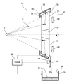
- FIG. 1 is a schematic configuration diagram showing an extreme ultraviolet light source device of this embodiment.
- FIG. 2 is a diagram illustrating the configuration of the debris trap device according to the first embodiment.
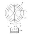
- FIG. 3 is a front view showing an example of a foil trap.
- FIG. 4 is a diagram showing the configuration of the debris discharge pipe.
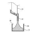
- FIG. 5 is a diagram for explaining the flow until the debris discharge pipe is closed.
- FIG. 6 is a diagram for explaining the flow until the debris discharge pipe is closed.
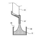
- FIG. 7 is a diagram for explaining the flow until the debris discharge pipe is closed.
- FIG. 8 is a diagram for explaining the flow until the debris discharge pipe is closed.
- FIG. 9 is a diagram in which a plurality of debris discharge pipes are provided.
- FIG. 10 is a diagram illustrating a configuration of a debris trap device according to the second embodiment.
- FIG. 11 is a diagram illustrating an example of a debris discharge pipe blockage detection method.
- FIG. 12 is a diagram illustrating an example of a debris discharge pipe blockage detection method.
- FIG. 13 is a diagram illustrating an example of a debris discharge pipe blockage detection method.
- FIG. 14 is a diagram illustrating an example of a debris discharge pipe blockage detection method.
- FIG. 15 is a schematic configuration diagram showing an LPP end ultraviolet light source device.
- FIG. 1 is a schematic configuration diagram showing an extreme ultraviolet light source device of the present embodiment.
- the extreme ultraviolet light source device (EUV light source device) 100 is a device that emits extreme ultraviolet light (EUV light) having a wavelength of 13.5 nm, for example, which can be used as a light source for semiconductor exposure.
- the EUV light source device 100 of the present embodiment is a DPP type EUV light source device, and more specifically, irradiates an energy beam such as a laser beam to a high-temperature plasma raw material supplied to an electrode surface that generates a discharge.
- the EUV light source apparatus 100 includes a chamber 11 that is a discharge vessel.
- the chamber 11 is roughly divided into two spaces by a partition wall 11a having an opening. One space is the discharge space 11b, and the other space is the condensing space 11c.
- a pair of discharge electrodes 21a and 21b which can rotate independently from each other, are arranged so as to face each other.
- the discharge electrodes 21a and 21b are discharge members for heating and exciting a high-temperature plasma raw material containing EUV radiation species.
- the pressure in the discharge space 11b is maintained in a vacuum atmosphere so that a discharge for heating and exciting the high-temperature plasma raw material is generated satisfactorily.
- an EUV condensing mirror (condensing mirror) 12 and a debris trap 13 are arranged in the condensing space 11c.
- the EUV collector mirror 12 collects EUV light emitted when the high-temperature plasma raw material is heated and excited. From the EUV extraction section 11d provided in the chamber 11, for example, an irradiation optical system (not shown) of the exposure apparatus. It leads to.
- the EUV collector mirror 12 is, for example, a grazing incidence type collector mirror, and has a structure in which a plurality of thin concave mirrors are arranged in a nested manner with high accuracy.
- the shape of the reflecting surface of each concave mirror is, for example, a spheroidal shape, a rotating paraboloid shape, or a Walter shape, and each concave mirror is a rotating body shape.
- the Walter shape is a concave shape in which the light incident surface is composed of a rotation hyperboloid and a rotation ellipsoid, or a rotation hyperboloid and a rotation paraboloid in order from the light incidence side.
- the EUV collector mirror 12 includes a plurality of concave mirrors each having a reflecting surface having a spheroidal shape, a Walter shape, or the like, each having a rotating body shape having a different diameter. These concave mirrors constituting the EUV collector mirror are arranged on the same axis so that the rotation center axes are overlapped so that the focal positions substantially coincide with each other. By arranging the concave mirrors in a nested manner with high accuracy in this way, the EUV collector mirror 12 can reflect EUV light with an oblique incident angle of about 25 ° or less well and collect it at one point. It becomes.
- each concave mirror described above is, for example, nickel (Ni).
- the reflecting surface of the concave mirror is configured as a very good smooth surface.
- the reflective material applied to the smooth surface is, for example, a metal film such as ruthenium (Ru), molybdenum (Mo), and rhodium (Rh).
- Ru ruthenium
- Mo molybdenum
- Rh rhodium
- the debris trap 13 captures debris generated as a result of plasma generation by discharge, and suppresses the debris from moving to the EUV light condensing unit. A specific configuration of the debris trap 13 will be described in detail later.
- the pair of discharge electrodes 21a and 21b arranged in the discharge space 11b is a metal disk-shaped member.
- the discharge electrodes 21a and 21b are made of a refractory metal such as tungsten, molybdenum, or tantalum.
- one discharge electrode 21a is a cathode and the other discharge electrode 21b is an anode.
- the discharge electrode 21a is disposed so that a part of the discharge electrode 21a is immersed in a container 23a that accommodates the high-temperature plasma raw material 22a.
- a rotating shaft 25a of a motor 24a is attached to a substantially central portion of the discharge electrode 21a. That is, when the motor 24a rotates the rotating shaft 25a, the discharge electrode 21a rotates.
- the motor 24 a is driven and controlled by the control unit 40.
- the rotating shaft 25a is introduced into the chamber 11 via, for example, a mechanical seal 26a.
- the mechanical seal 26a allows rotation of the rotary shaft 25a while maintaining a reduced pressure atmosphere in the chamber 11.
- the discharge electrode 21b is also arranged so that a part of the discharge electrode 21b is immersed in a container 23b that accommodates the high-temperature plasma raw material 22b.
- a rotating shaft 25b of a motor 24b is attached to a substantially central portion of the discharge electrode 21b. That is, when the motor 24b rotates the rotating shaft 25b, the discharge electrode 21b rotates.
- the motor 24 b is driven and controlled by the control unit 40.
- the rotating shaft 25b is introduced into the chamber 11 through, for example, a mechanical seal 26b.
- the mechanical seal 26b allows rotation of the rotating shaft 25b while maintaining a reduced pressure atmosphere in the chamber 11.
- the liquid high-temperature plasma raw materials 22a and 22b on the surfaces of the discharge electrodes 21a and 21b are transported to the discharge region as the discharge electrodes 21a and 21b rotate.
- the discharge region is a space where a discharge occurs between the electrodes 21a and 21b, and is a portion where the distance between the edge portions of the peripheral portions of the electrodes 21a and 21b is the shortest.
- the high temperature plasma raw materials 22a and 22b a molten metal, for example, liquid tin (Sn) is used.
- the high-temperature plasma raw materials 22a and 22b also function as power supply conductors that supply power to the discharge electrodes 21a and 21b.
- the containers 23 a and 23 b are connected to the pulse power supply unit 27 via insulating power introduction units 11 e and 11 f that can maintain a reduced pressure atmosphere in the chamber 11.
- the containers 23a and 23b and the tin 22a and 22b which are high temperature plasma raw materials are conductive. A part of the discharge electrode 21a and a part of the discharge electrode 21b are immersed in the tin 22a and 22b, respectively.
- pulse power can be applied between the discharge electrodes 21a and 21b by applying pulse power from the pulse power supply unit 27 between the containers 23a and 23b.
- the containers 23a and 23b are provided with a temperature adjusting mechanism for maintaining the tins 22a and 22b in a molten state.
- the pulse power supply unit 27 applies pulse power having a short pulse width between the containers 23a and 23b, that is, between the discharge electrodes 21a and 21b.
- the pulse power supply unit 27 is driven and controlled by the control unit 40.
- the laser source 28 is an energy beam irradiation unit that irradiates laser light (energy beam) to the tin 22a on the discharge electrode 21a transported to the discharge region.
- the laser source 28 is, for example, an Nd: YVO 4 laser device (Neodymium-doped Yttrium Orthovanadate laser device).
- the laser light L emitted from the laser source 28 enters the window 11g of the chamber 11 through a laser light condensing unit and the like, and is guided onto the discharge electrode 21a.
- the control unit 40 controls the irradiation timing of the laser light from the laser source 28.
- the pulsed power is applied to the discharge electrodes 21a and 21b by the pulse power supply unit 27 and the high temperature plasma material 22a transported to the discharge region is irradiated with laser light, the high temperature plasma material is vaporized. Pulse discharge is started between the electrodes 21a and 21b. As a result, plasma P is formed by the high temperature plasma raw materials 22a and 22b. Then, when the plasma P is heated and excited by a large current flowing at the time of discharge, EUV light is emitted from the high temperature plasma P. As described above, since pulse power is applied between the discharge electrodes 21a and 21b, the discharge becomes pulse discharge, and the emitted EUV light becomes pulsed light emitted in a pulse shape.
- the debris trap 13 In the EUV light source device 100, for example, debris such as metal powder generated by sputtering a metal (for example, a pair of discharge electrodes 21a and 21b) in contact with the high-temperature plasma P, or tin (Sn) as a high-temperature plasma raw material. ) Debris caused by 22a and 22b is generated. These debris obtains large kinetic energy through the process of plasma contraction and expansion. That is, debris generated from the high temperature plasma P is ions or neutral atoms that move at high speed, and such debris hits the EUV collector mirror 12 to scrape the reflective surface or deposit on the reflective surface. There is a risk of reducing the reflectance of EUV light.
- debris such as metal powder generated by sputtering a metal (for example, a pair of discharge electrodes 21a and 21b) in contact with the high-temperature plasma P, or tin (Sn) as a high-temperature plasma raw material.
- Debris caused by 22a and 22b is generated.
- FIG. 2 is a cross-sectional view of the debris trap 13 viewed from a direction orthogonal to the optical axis of the EUV light.
- the debris trap 13 includes a foil trap (rotary foil trap) 30 having a rotating function.
- the foil trap 30 includes a plurality of foils 31 arranged radially in the radial direction around an axis that coincides with the optical axis of the EUV light, as shown in FIG.
- the foil 31 is constituted by a thin film (foil) or a thin flat plate (plate), and the thin film and the flat plate are collectively referred to as “foil” in this specification.
- the foil 31 is supported at its radially inner end by a central column 32 arranged concentrically, and at its radially outer end by a first outer ring 33 and a second outer ring 34 which are ring-shaped supports.
- the first outer ring 33 supports the high temperature plasma P side of the foil 31
- the second outer ring 34 supports the EUV emission side of the foil 31.
- the foil 31 is arranged and supported so that its plane is parallel to the optical axis of the EUV light. Therefore, when the foil trap 30 is viewed from the extreme ultraviolet light source (high temperature plasma P) side, as shown in FIG. 3, the support body constituted by the center column 32, the first outer ring 33, and the second outer ring 34 is shown. Otherwise, only the thickness of the foil 31 is visible. Therefore, most of the EUV light from the high temperature plasma P can pass through the foil trap 30.
- the plurality of foils 31 of the foil trap 30 function to increase the pressure by reducing the conductance of the divided space by finely dividing the arranged space. Therefore, the speed of the debris D from the high temperature plasma P decreases because the collision probability increases in a region where the pressure is increased by the foil trap 30.
- the debris D whose speed has been reduced is captured by the foil 31 and the support body of the foil 31 (the central support column 32, the first outer ring 33, and the second outer ring 34).
- the central support column 32 has a shape that shields light having a minimum incident angle or less determined from the configuration of the EUV collector mirror 12, and thus generally has a cone shape. Therefore, the central support column 32 may also be called a cone.
- the foil 31 and the central column 32 constituting the foil trap 30 are formed from a high heat resistant material such as molybdenum (Mo), for example.
- the debris trap 13 includes a cover member 35 that surrounds the outer peripheral portion of the foil trap 30, a cover heating unit 36 that heats the cover member 35, and a debris discharge pipe formed on the cover member 35. 37.
- the cover heating unit 36 includes a sheath heater or the like, and heats the cover member 35 to a melting point (235 ° C.) or higher of tin that is a high-temperature plasma raw material.
- the cover heating unit 36 is controlled by the control unit 40 so that the temperature of the cover member 35 is maintained at a temperature corresponding to the melting point of tin, which is a high-temperature plasma raw material.
- the debris discharge pipe 37 is, for example, a cylindrical member made of the same material as the cover member 35, and extends along the vertical direction and is connected to the bottom of the cover member 35 as shown in FIG. 4. Yes.
- the upper end portion of the debris discharge pipe 37 passes through the bottom portion of the cover member 35 and communicates with the inside of the cover member 35, and the lower end portion of the debris discharge pipe 37 serves as a debris discharge port from which debris is discharged.
- the foil trap 30 rotates about the axis of the central support column 32 as a rotation axis, and captures relatively low-speed debris emitted from the high temperature plasma P together with EUV light.
- debris D due to tin as a high-temperature plasma raw material is captured by each foil 31 of the foil trap 30, or the traveling direction is different from the EUV mirror side. Or be biased.
- the tin D captured by the foil trap 30 may be thrown off by the rotating foil 31 or may be adhered and deposited on the foil 31.
- the foil trap 30 is disposed in the vicinity of the high temperature plasma P and receives radiation from the high temperature plasma P. Therefore, the temperature of each foil 31 is higher than 235 ° C., which is the melting point of tin. Therefore, the tin D deposited and deposited on the foil 31 is liquefied in the course of time, and as shown in FIG. 2, the centrifugal force (arrow CF) generated by the rotation of the foil trap 30 causes the outer side in the radial direction along each foil 31. It moves and separates from the outer edge of each foil 31. Tin D separated from the foil trap 30 adheres to and accumulates on the inner surface of the cover member 35. Since the cover member 35 is heated to 235 ° C.
- the cover heating unit 36 by the cover heating unit 36, the tin D adhering to the inner surface of the cover member 35 is immediately melted to a size of a droplet, and due to gravity Collect at the bottom of the cover member 35.
- An opening of the debris discharge pipe 37 is provided at the lower part of the cover member 35. Therefore, the molten tin D collected at the lower part of the cover member 35 is discharged from the opening of the debris discharge pipe 37 to the outside of the cover member 35 through the debris discharge pipe 37 from the debris discharge port.
- the debris trap 13 has a tin reservoir 38 as a debris storage portion that receives and accumulates tin D discharged from the debris discharge pipe 37 immediately below the debris discharge port of the debris discharge pipe 37.
- a tin reservoir heating section 39 as an accommodating section heating section for heating the tin reservoir 38;
- the tin reservoir heating unit 39 is configured by a sheath heater or the like, and heats the tin reservoir 38 to a melting point (235 ° C.) or higher of tin that is a high-temperature plasma raw material.
- the tin reservoir heating unit 39 is controlled by the control unit 40 so that the temperature of the tin reservoir 38 is maintained at a temperature corresponding to the melting point of tin, which is a high-temperature plasma raw material. That is, the tin D received by the tin reservoir 38 is immediately melted and collected in the tin reservoir 38 in a liquefied state.
- the debris trap 13 includes a temperature sensor 41 as a temperature measuring unit that detects the temperature of the debris discharge pipe 37.
- the temperature sensor 41 is, for example, a contact-type temperature sensor, and is attached to the debris discharge pipe 37 as shown in FIG. Note that a non-contact temperature sensor may be used as the temperature sensor 41.
- the temperature sensor 41 detects the surface temperature of the debris discharge pipe 37 and outputs the temperature detection signal to the control unit 40.
- the control unit 40 acquires a temperature detection signal from the temperature sensor 41 and obtains the measured temperature of the debris discharge pipe 37. Next, the control unit 40 compares the measured temperature with a preset reference temperature, and detects blockage of the debris discharge pipe 37 due to solid tin.
- the control unit 40 determines that the debris discharge pipe 37 is blocked with tin D when the measured temperature of the debris discharge pipe 37 is lower than the reference temperature.
- the reference temperature is set to a temperature corresponding to the melting point of tin (235 ° C.).
- the reference temperature may be a temperature provided with a predetermined margin with respect to the temperature corresponding to the melting point of tin (235 ° C.).
- the control unit 40 When detecting the blockage of the debris discharge pipe 37, the control unit 40 notifies at least the operator of this. Specifically, for example, an error signal is sent to a host control unit (not shown) that controls the entire EUV light source apparatus 100.
- the host controller that has received the error signal urges the operator to manually stop the EUV emission by turning on a warning lamp or operating a buzzer.
- the host control unit that has received the error signal may be configured to automatically stop the EUV light emission in the EUV light source device 100.
- a debris trap device is constituted by the debris trap 13 and the control unit 40 having the above-described blocking detection function.
- the temperature sensor 41 and the control unit 40 having the above-described blockage detection function constitute a blockage detection unit. In addition, you may comprise so that said high-order control part may have said obstruction
- the main factors that cause clogging of the debris discharge pipe 37 with solid tin are a malfunction of the cover heating section 36 that heats the cover member 35 and a malfunction of the tin reservoir heating section 39 that heats the tin reservoir 38.
- an abnormality occurs in the cover heating unit 36, it is difficult to maintain the temperature of the cover member 35 at 235 ° C. or higher, which is the melting point of tin.
- the debris discharge pipe 37 connected to the bottom of the cover member 35 is thermally connected to the cover member 35. Therefore, when the temperature of the cover member 35 is maintained above the melting point of tin, the debris discharge pipe 37 The temperature of 37 is also equal to or higher than the melting point of tin.
- the temperature of the debris discharge pipe 37 also falls below 235 ° C., which is the melting point of tin.
- the droplets of tin D fall one after another from the debris discharge pipe 37 to the same portion of the tin reservoir 38 (just below the debris discharge port). Therefore, the tin D that has fallen onto the tin reservoir 38 and has become a solid deposits in a sarcophagus shape as shown in FIG.
- the debris discharge port of the debris discharge pipe 37 is closed with the solid tin D as shown in FIG. Then, the tin D melted by the cover heating unit 36 is not discharged from the debris discharge pipe 37, and the debris discharge pipe 37 is completely closed as shown in FIG.
- the heating of the cover member 35 is maintained when there is no problem in the cover heating unit 36, the heating of the debris discharge pipe 37 that is thermally connected to the cover member 35 is also maintained.
- the solid tin D that has accumulated from the tin reservoir 38 in a stalagmite shape and closed the debris discharge pipe 37 has a large heat capacity. Therefore, even if the debris discharge pipe 37 is heated, it is difficult to dissolve the solid tin D that closes the debris discharge pipe 37 and eliminate the closed state of the debris discharge pipe 37. Therefore, when the debris discharge pipe 37 is blocked by solid tin D deposited in a stone wall shape, the temperature of the debris discharge pipe 37 is lower than the melting point of tin. Therefore, by monitoring the temperature of the debris discharge pipe 37, the blockage of the debris discharge pipe 37 due to the malfunction of the tin reservoir heating unit 39 can also be detected.
- the debris discharge pipe 37 When the debris discharge pipe 37 is completely closed, it becomes impossible to discharge the tin D from the cover member 35 to the outside, and the tin D accumulates in the cover member 35. If the amount of tin D accumulated in the cover member 35 increases as it is, the foil 31 of the foil trap 30 finally comes into contact with the accumulated tin D. Then, the rotation function of the foil trap 30 becomes impossible, or a part of the foil 31 is broken and the debris prevention performance is lowered.
- the control unit 40 monitors the temperature of the debris discharge pipe 37 and detects that the temperature of the debris discharge pipe 37 is lower than the melting point of tin, the debris discharge pipe 37 is blocked by the solid tin D. An error signal is output. Thus, since the blockage of the debris discharge pipe 37 is detected when the temperature of the debris discharge pipe 37 is lower than the melting point of tin, the blockage can be detected relatively early.
- the tin D and the foil trap 30 accumulated in the cover member 35 are determined. Before the contact, it is possible to detect the blockage of the debris discharge pipe 37 at an early stage. Therefore, before the damage to the foil trap 30 itself (the damage to the foil 31 or the like) occurs, it is possible to take measures such as terminating the exposure process or repairing the cover member 35 or the like. It is possible to prevent the foil trap 30 from contacting the accumulated tin in advance.
- the malfunction of the cover heating unit 36 that heats the cover member 35 is one of the factors that cause the debris discharge pipe 37 to be blocked by tin.
- a temperature sensor is provided in the vicinity of the cover heating unit 36 in the cover member 35 to monitor the temperature of the cover member 35, or from a power source (not shown) to the cover heating unit 36. A method of diagnosing disconnection of the power supply line to the cover heating unit 36 by monitoring the power supply status of the power supply is conceivable.
- the cover heating unit that heats the cover member 35 generally employs a sheath heater, and there are various failure modes.
- a part of the heater may not function and only the remaining part functions. In this case, disconnection of the power supply line from the power source to the cover heating unit 36 does not occur.
- production position of the part which a heater does not function is random, it becomes difficult to grasp
- the temperature sensor 41 is installed in the debris discharge pipe 37 and the temperature of the debris discharge pipe 37 is monitored, so that the cover heating unit 36 and the tin reservoir heating unit 39 have a relatively simple configuration. Can be properly detected. Further, as described above, regardless of which one of the cover heating unit 36 and the tin reservoir heating unit 39 is defective, the debris discharge pipe 37 is blocked with solid tin, and the temperature of the debris discharge pipe 37 is lower than the melting point of tin. Therefore, by monitoring the temperature of the debris discharge pipe 37, this can be reliably detected regardless of whether the cover heating unit 36 or the tin reservoir heating unit 39 is defective. Thus, since it is not necessary to provide each of the cover heating unit 36 and the tin reservoir heating unit 39 with a means for detecting a problem, it is possible to reduce the size of the apparatus and reduce the cost.
- the cover heating unit 36 and the tin reservoir heating unit 39 heat the cover member 35 and the tin reservoir 38 to a temperature equal to or higher than the melting point of tin, which is a high-temperature plasma raw material.
- the cover member 35 and the debris discharge pipe 37 thermally connected to the cover member 35 can be heated, and debris (tin) collected by the cover member 35. Therefore, it is possible to suppress a problem that the debris discharge pipe 37 is blocked.
- the tin reservoir 38 the debris (tin) discharged from the debris discharge pipe 37 can be stored in the tin reservoir 38 in a liquid state. Accordingly, it is possible to suppress a problem that tin grows in a stalagmite shape from the tin reservoir 38 and closes the debris discharge pipe 37.
- the cover heating unit 36 and the tin reservoir heating unit 39 constitute a blockage suppressing unit.
- the blockage suppression part it is possible to suppress the debris captured by the cover member 35 from accumulating inside the cover member 35, and the debris accumulated inside the cover member 35 and the foil trap 30 are in contact with each other. Can be suppressed. Therefore, it is possible to prevent the foil trap 30 from being damaged and the debris capturing function from being lowered. Further, even when a defect occurs in the cover heating unit 36 or the tin reservoir heating unit 39 and the debris discharge pipe 37 is blocked, this can be properly detected by the blockage detection unit, so that the debris trap can be stably detected.
- the device 13 can be activated.
- the delay time from when the error signal is transmitted until the tin trapped in the cover member 35 collides with the foil trap 30 is obtained in advance, and the number of times of EUV emission during the delay time can be grasped in advance. That's fine. As a result, it is possible to create a workpiece that can continue the exposure processing even after the error signal is transmitted, and to reduce the number of workpieces that end in a halfway state.
- the several temperature sensor 41 may be attached to the debris discharge pipe 37, and temperature measurement may be multiplexed.
- the temperature sensor 41 may cause contact failure or malfunction due to deterioration.
- the control unit 40 has the temperature of the debris discharge pipe 37 not lower than the melting point of tin and the debris discharge pipe 37 is not blocked by tin. Based on the temperature detection signal from the temperature sensor 41, the temperature of the debris discharge pipe 37 is erroneously recognized as being lower than the melting point of tin. In this case, since the control unit 40 transmits an error signal to the host control unit, EUV light emission is stopped.
- the operator opens the chamber 11 to disassemble the foil trap 30 and checks whether or not the debris discharge pipe 37 is closed, even though the foil trap 30 is not defective. As described above, the operator performs the inspection work even though the debris discharge pipe 37 is not blocked, and the exposure processing of the workpiece is stopped until it is judged that there is no abnormality and returns to the state where EUV light emission is possible again. There must be.
- the debris discharge pipe 37 is not subjected to any trouble except that all of the plurality of temperature sensors 41 deteriorate and cause poor contact or malfunction. It is possible to more reliably detect the problem of being blocked by tin. That is, when only a part of the plurality of temperature sensors 41 deteriorates, the temperature detection signals from some of the deteriorated temperature sensors 41 are different from the temperature detection signals from other normal temperature sensors 41. .
- a temperature detection signal sent from a plurality of temperature sensors 41 includes a signal corresponding to a temperature at which the temperature of the debris discharge pipe 37 is below the melting point of tin and a signal corresponding to a temperature at which the temperature does not fall below the melting point of tin. If they are mixed, it can be determined that some of the temperature sensors 41 have deteriorated. In this case, the operator need only inspect and replace the temperature sensor 41 without disassembling the foil trap 30. In this manner, unnecessary maintenance due to the measurement error of the temperature sensor 41 can be suppressed. Therefore, the repair time of the EUV light source apparatus 100 can be greatly shortened.
- a plurality of debris discharge pipes 37 may be provided at the bottom of the cover member 35.
- the number of the debris discharge pipes 37 is two, but may be three or more.
- the temperature sensor 41 is not shown, but each debris discharge pipe 37 is provided with a temperature sensor 41.
- the solid tin D deposited in a stalagmite shape from the tin reservoir 38 toward the debris discharge pipe 37 does not necessarily block the plurality of debris discharge pipes 37 at the same time. Therefore, if a plurality of debris discharge pipes 37 are provided, even if one debris discharge pipe 37 is closed with solid tin D, until the remaining debris discharge pipe 37 is closed with solid tin D, tin is removed from the cover member 35.
- the EUV light source device 100 can be discharged to the outside. In this way, by providing a plurality of debris discharge pipes 37, it is possible to prevent a situation where tin D cannot be discharged from the cover member 35 to the outside. In addition, the operation of the EUV light source device 100 can be continued without damaging the foil trap 30 until all of the plurality of debris discharge pipes 37 are closed with the solid tin D. That is, by providing a plurality of debris discharge pipes 37, the probability that the operation of the EUV light source device 100 can be continued for a longer period of time is higher than when only one debris discharge pipe 37 is provided.
- FIG. 10 is a diagram illustrating a configuration of the debris trap 13 in the second embodiment.
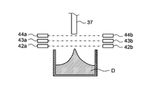
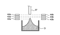
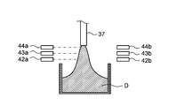
- a plurality of position sensors 42 to 44 are provided as a debris detection unit for detecting the presence or absence of debris.
- the position sensors 42 to 44 are arranged in the order of the position sensors 42, 43, 44 from the side closer to the tin reservoir 38.
- the position of the position sensor 44 is set near the debris discharge port of the debris discharge pipe 37.
- the position sensor 42 is disposed between the debris discharge pipe 37 and the tin reservoir 38 so as to face each other with the debris discharge pipe 37 interposed therebetween, and a light receiving device 42a made of, for example, a semiconductor laser, and a light receiving device that receives light from the light emitting device 42a. And an optical sensor.
- the position sensor 43 includes a light emitter 43a and a light receiver 43b
- the position sensor 44 includes a light emitter 44a and a light receiver 44b.
- the position sensors 42 to 44 detect whether or not an object is present in the optical path of the light emitted from the light emitter.
- the light emitted from the light emitter When there is no object in the optical path, the light emitted from the light emitter reaches the light receiver facing the light object without being blocked by the object, and is detected by the light receiver. On the other hand, when an object is present in the optical path, the light emitted from the light emitter is blocked by the object and does not reach the opposing light receiver. Therefore, the light emitted from the light emitter is not detected by the light receiver.
- the position sensors 42 to 44 detect whether tin D is present in the optical path between the light emitter and the light receiver, depending on whether the light emitted from the light emitter is detected by the light receiver. It is. These position sensors 42 to 44 monitor tin D that grows in a stalagmite shape from the tin reservoir 38 toward the debris discharge pipe 37 of the cover member 35, and tin discharged from the debris discharge pipe 37 to the tin reservoir 38. Used to monitor D.
- the control unit 40 determines that tin D that has grown in a stalagmite shape from the tin reservoir 38 has reached the position of the optical path of the position sensor 42.
- the predetermined time is the time during which the droplet-shaped tin D emitted from the debris discharge pipe 37 toward the tin reservoir 38 blocks the light from the light emitter of the position sensor, that is, the debris discharge pipe 37 discharges the light. The time required for the tin D to be passed through the debris detection region of the position sensor to be longer is set.
- the light receiver 42b continues to be unable to detect light from the light emitter 42a.
- the control unit 40 Determines that the tin D grown in the shape of a sarcophagus from the tin reservoir 38 has reached the position of the optical path of the position sensor 43.
- the control unit 40 causes the tin D grown in the shape of stalagmite from the tin reservoir 38 to debris. It is determined that the exhaust pipe 27 has been reached.
- a plurality of position sensors are arranged in the vertical direction between the tin reservoir 38 and the debris discharge pipe 37, and the photodetection state of the light receiver in each of the arranged position sensors is monitored, thereby the tin reservoir 38. It is possible to detect a state in which tin D that has fallen on the surface grows like a stone wall. In particular, by setting the position of the optical path of the position sensor 44 in the vicinity of the debris discharge port of the debris discharge pipe 37, it is possible to detect a state immediately before the debris discharge pipe 37 is blocked by tin D.
- the control unit 40 outputs an error signal corresponding to the light detection state of the light receivers 42b to 44b in the position sensors 42 to 44.
- the control unit 40 determines that the upper end of tin D grown in a stalagmite shape from the tin reservoir 38 is the optical path of the position sensor 42. If it is determined that the position has been reached, an error signal is sent to the host controller in order to turn on the warning lamp.
- control unit 40 may send different error signals depending on the state of tin D that has grown in a stalagmite shape from the tin reservoir 38.
- the control unit 40 may send an error signal that gives a stronger warning as the upper end portion of tin D grown like a stone wall approaches the debris discharge pipe 37.
- the EUV light emission in the EUV light source device 100 is performed with respect to the upper control unit. May be configured to automatically stop.
- control unit 40 detects the blockage of the debris discharge pipe 37 due to the malfunction of the cover heating unit 36 that heats the cover member 35 using the detection signals of the position sensors 42 to 44. Since EUV light emission is basically pulse light emission at a constant frequency, the amount of debris (tin) generated during EUV light emission per unit time is substantially constant. Therefore, the amount of tin D discharged from the debris discharge pipe 37 per unit time is also substantially constant. In the EUV light source device 100, tin D released to the outside from the debris discharge pipe 37 becomes droplets depending on the amount of debris (tin) generated, the capacity of the cover member 35, the viscosity of tin, and the like. That is, droplet-shaped tin D is discharged from the debris discharge pipe 37 intermittently at substantially regular intervals.
- the position sensors 42 to 44 are placed in the space where the debris of the debris discharge pipe 37 is discharged (the space below the debris discharge pipe 37). It arrange
- droplet-shaped tin D is discharged from the debris discharge pipe 37 intermittently at substantially constant intervals.
- the light reaching the light receivers 42b to 44b from the light emitters 42a to 44a of the position sensors 42 to 44 is also intermittently blocked or dimmed at a substantially constant interval.
- the light receivers 42b to 44b detect light from the light emitters 42a to 44b intermittently at substantially constant intervals.
- the control unit 40 determines that the debris discharge pipe 37 is not blocked by tin D, and the position sensor 42 When the .about.44 continuously detects light, the control unit 40 determines that the debris discharge pipe 37 is blocked with tin D.
- the control unit 40 discharges the debris. It is determined that the tube 37 is blocked by tin D.
- the control unit 40 determines that the debris discharge pipe 37 is blocked and tin D is not discharged based on the light detection states of the light receivers 42b to 44b in the position sensors 42 to 44, an error signal is sent to the host control unit. Is sent out. Thereby, the EUV light emission in the EUV light source apparatus 100 is automatically stopped. In addition, even when the cover member 35 is replaced with a new one, when no tin adheres to the inside of the cover member 35, or even when the debris discharge pipe 37 is not blocked, the cover member 35 has a certain amount after the EUV emission. If debris does not accumulate, tin D is not discharged from the debris discharge pipe 37 to the outside. In this case, since the position sensors 42 to 44 continuously detect light even if the debris discharge pipe 37 is not blocked, the control unit 40 erroneously detects that the debris discharge pipe 37 is blocked by tin D. I will judge.
- the initial time from the start of EUV emission when the cover member 35 is new to the time when tin D is released from the debris discharge pipe 37 is obtained in advance. After the initial time has elapsed, it is determined whether or not the debris discharge pipe 37 is blocked (whether the position sensors 42 to 44 detect light intermittently or continuously at a constant cycle). Is preferred.
- the position sensor is disposed on the debris discharge side of the debris discharge pipe 37, and the presence or absence of debris on the debris discharge side is monitored, so that the stone wall is moved from the tin reservoir 38 toward the debris discharge pipe 37.
- the debris discharge pipe 37 can be detected even when the debris discharge pipe 37 is closed due to a failure of the cover heating unit 36 that heats the cover member 35.
- the tin D since it is possible to detect tin D growing in a stalagmite shape from the tin reservoir 38 toward the debris discharge pipe 37, the tin D reaches the debris discharge pipe 37 before the debris discharge pipe 37 is completely closed. Before) the risk of blockage of the debris discharge pipe 37 can be detected early. That is, it becomes possible to stop the EUV emission before the debris discharge pipe 37 is completely closed.
- the case where either the temperature sensor 41 or the position sensors 42 to 44 is employed as the blockage detection unit has been described.
- the temperature sensor 41 and the position sensors 42 to 44 may be used in combination.
- the case where a laser is used as the energy beam irradiated to the high-temperature plasma raw material has been described, but an ion beam, an electron beam, or the like can be used instead of the laser.
- the case where the present invention is applied to a DPP type EUV light source apparatus has been described.
- the present invention is also applicable to an LPP type EUV light source apparatus.
- the LPP method is a method of generating plasma by irradiating a target material with a plasma generation driver laser and exciting the target material.
- FIG. 15 is a schematic configuration diagram showing an LPP type EUV light source apparatus 200.
- the EUV light source apparatus 200 has a light source chamber 51.
- the inside of the light source chamber 51 is maintained in a vacuum state by a vacuum pump or the like.
- the light source chamber 51 is provided with a raw material supply nozzle 53 for supplying a raw material (high temperature plasma raw material) 52 which is an EUV radiation species.
- the raw material supply nozzle 53 supplies the raw material 52 (for example, droplet-shaped tin) supplied from the raw material supply unit 54 to a predetermined target area.
- the EUV light source device 200 includes an excitation laser beam generator (energy beam irradiation unit) 55 that emits a laser beam L.
- the laser beam L from the excitation laser beam generator 55 is collected by the laser beam collector 56 and enters the chamber 51 through the laser beam entrance window 57 formed in the chamber 51.
- the laser beam L incident on the inside of the chamber 51 passes through a laser beam passage hole provided at a substantially central portion of the EUV collector mirror (condenser mirror) 58 and irradiates the source material 52 emitted from the source material supply nozzle 53.
- the excitation laser light generator 55 is a pulse laser device having a repetition frequency of several kHz, for example, and a carbon dioxide (CO 2 ) laser, a YAG laser, or the like is used.
- the raw material supplied from the raw material supply nozzle 53 to the target area is heated and excited by irradiation with the laser beam L to become high temperature plasma P, and EUV light is emitted from the high temperature plasma P.
- the emitted EUV light is reflected by the EUV collector mirror 58 toward the EUV light extraction portion 59 formed in the chamber 51, and is collected at the condensing point (intermediate condensing point) of the EUV collector mirror 58.
- the light is emitted from the EUV light extraction unit 59.
- the EUV light emitted from the EUV light extraction unit 59 enters an irradiation optical system or the like of an exposure apparatus (not shown) connected to the EUV light source apparatus 200.
- the raw material 52 is heated and excited by irradiation with a pulsed laser to become high-temperature plasma P, so that EUV light emission is pulsed emission.
- the EUV collector mirror 58 is a spherical reflecting mirror coated with, for example, a multilayer film of molybdenum and silicon.
- the laser light There may be no need for a through hole.
- the laser light L for generating high temperature plasma may reach the EUV light extraction unit 59 as stray light. Therefore, a spectral purity filter (not shown) that transmits EUV light and does not transmit laser light L may be disposed in front of the EUV light extraction unit 59 (on the high-temperature plasma P side).
- the above-described debris trap 13 may be disposed between the high temperature plasma P and the EUV collector mirror 58. Also in this case, like the DPP (DLP) EUV light source device 100 described above, the debris trap 13 functions to capture debris generated from the high temperature plasma P and allow only EUV light to pass through.
- the said debris is not limited to tin
- Raw materials other than tin are used as a high temperature plasma raw material. If so, the debris trap 13 can capture debris corresponding to the high temperature plasma raw material used.
- the EUV light source device is used as a semiconductor exposure light source.
- the present invention is not limited to this.
- the EUV light source device can be used as a light source for an exposure mask inspection device or the like. .
- the debris trap device of the present invention since it is possible to detect the blockage of the debris discharge pipe that discharges the debris from the cover member, the debris accumulated on the cover member and the foil trap come into contact with each other and damage the foil trap Appropriate measures can be taken before such as the occurrence. Therefore, the debris capturing function can be prevented from being lowered, and debris can be captured stably, which is useful.
Landscapes
- Physics & Mathematics (AREA)
- General Physics & Mathematics (AREA)
- Engineering & Computer Science (AREA)
- Optics & Photonics (AREA)
- Plasma & Fusion (AREA)
- X-Ray Techniques (AREA)
- Exposure And Positioning Against Photoresist Photosensitive Materials (AREA)
- Exposure Of Semiconductors, Excluding Electron Or Ion Beam Exposure (AREA)
Abstract
回転式ホイルトラップとカバー部材とを備えるデブリトラップ装置において、回転式ホイルトラップの不具合を抑制して安定してデブリを捕捉することができるデブリトラップ装置、及びそれを備えた極端紫外光光源装置が開示される。デブリトラップ(13)は、極端紫外光を放出するプラズマの近傍に配置された複数のホイル(31)を有し、極端紫外光を通過しプラズマから発生するデブリを捕捉する回転可能なホイルトラップ(30)と、ホイルトラップ(30)の外周部を包囲してデブリを捕集するカバー部材(35)と、カバー部材(35)で捕集したデブリをカバー部材(35)の外部へ排出するためのデブリ排出管(37)と、を備える。さらに、デブリトラップ(13)は、デブリ排出管37がデブリによって閉塞することを検出する閉塞検出部を備える。
Description
本発明は、高温プラズマから放出されるデブリを捕捉するデブリトラップ装置、及びそのデブリトラップ装置を備える極端紫外光光源装置に関する。
近年、半導体集積回路の微細化、高集積化につれて、露光用光源の短波長化が進められている。次世代の半導体露光用光源としては、特に波長13.5nmの極端紫外光(以下、「EUV(Extreme Ultra Violet)光」ともいう。)を放射する極端紫外光光源装置(以下、「EUV光源装置」ともいう。)の開発が進められている。
EUV光源装置において、EUV光を発生させる方法はいくつか知られているが、そのうちの一つに極端紫外光放射種(以下、「EUV放射種」という。)を加熱して励起することにより高温プラズマを発生させ、その高温プラズマからEUV光を取り出す方法がある。
このような方法を採用するEUV光源装置は、高温プラズマの生成方式により、LPP(Laser Produced Plasma:レーザ生成プラズマ)方式と、DPP(Discharge Produced Plasma:放電生成プラズマ)方式とに分けられる。
EUV光源装置において、EUV光を発生させる方法はいくつか知られているが、そのうちの一つに極端紫外光放射種(以下、「EUV放射種」という。)を加熱して励起することにより高温プラズマを発生させ、その高温プラズマからEUV光を取り出す方法がある。
このような方法を採用するEUV光源装置は、高温プラズマの生成方式により、LPP(Laser Produced Plasma:レーザ生成プラズマ)方式と、DPP(Discharge Produced Plasma:放電生成プラズマ)方式とに分けられる。
DPP方式のEUV光源装置は、極端紫外光放射源を含む放電ガスが供給された電極間に高電圧を印加して、放電により高密度高温プラズマを生成し、そこから放射される極端紫外光を利用するものである。DPP方式において、放電を発生させる電極表面にSn(スズ)やLi(リチウム)等の原料を供給し、当該原料に対してレーザビーム等のエネルギービームを照射して当該原料を気化し、その後、放電によって高温プラズマを生成する方法が提案されている。このような方式は、LDP(Laser Assisted Gas Discharge Produced Plasma)方式と称されることもある。
一方、LPP方式のEUV光源装置は、レーザ光をターゲット材料に照射し、当該ターゲット材料を励起させてプラズマを生成するものである。
上述したEUV光源装置では、高温プラズマから種々のデブリが発生する。このようなデブリを捕捉するために、EUV光源装置は、ホイルトラップ(フォイル・トラップ)を用いたデブリトラップ装置を備えるのが一般的である。デブリトラップ装置としては、例えば、特許文献1(特表2012-513653号公報)に記載の技術がある。この技術は、回転機能を有するホイルトラップ(回転式ホイルトラップ)と、その回転式ホイルトラップを包囲するカバー部材とを備えるものである。
上述したEUV光源装置では、高温プラズマから種々のデブリが発生する。このようなデブリを捕捉するために、EUV光源装置は、ホイルトラップ(フォイル・トラップ)を用いたデブリトラップ装置を備えるのが一般的である。デブリトラップ装置としては、例えば、特許文献1(特表2012-513653号公報)に記載の技術がある。この技術は、回転機能を有するホイルトラップ(回転式ホイルトラップ)と、その回転式ホイルトラップを包囲するカバー部材とを備えるものである。
回転式ホイルトラップは、中央に配置された回転軸を中心として、半径方向に放射状に配置された複数のホイル(薄膜や薄い平板)を備え、上記回転軸を中心に複数のホイルを回転させることでプラズマから飛来するデブリを捕捉する。ホイルに捕捉されたデブリは、回転式ホイルトラップの回転により生じる遠心力によって各ホイルに沿って半径方向外側に移動し、各ホイルから離脱する。
各ホイルから離脱したデブリは、カバー部材によって捕集され、カバー部材内面に付着する。カバー部材は所定の加熱手段によって加熱されており、当該加熱によりカバー部材内面に付着したデブリが固化しないようにしている。カバー部材内面に付着したデブリは、重力によりカバー部材下部に集まり、カバー部材下部から排出管を介してカバー部材の外に排出される。
各ホイルから離脱したデブリは、カバー部材によって捕集され、カバー部材内面に付着する。カバー部材は所定の加熱手段によって加熱されており、当該加熱によりカバー部材内面に付着したデブリが固化しないようにしている。カバー部材内面に付着したデブリは、重力によりカバー部材下部に集まり、カバー部材下部から排出管を介してカバー部材の外に排出される。
しかしながら、上記特許文献1(特表2012-513653号公報)に記載の技術にあっては、カバー部材の加熱手段に不具合が生じると、カバー部材の加熱が不十分となり、当該カバー部材と熱的に接続されている排出管の温度が下がってしまう。すると、排出管の内壁にデブリが固体化して堆積するようになり、最終的に排出管がデブリによって閉塞されてしまう。
このように何らかの不具合により排出管が閉塞されると、デブリをカバー部材から外部に排出することが不可能となり、カバー部材内にデブリが堆積されてしまう。すると、この溜まったデブリに回転するホイルトラップが接触し、ホイルトラップが破損したり、ホイルトラップが回転不能となったりすることで、デブリの捕捉機能が低下するおそれがある。
そこで、本発明は、回転式ホイルトラップとカバー部材とを備えるデブリトラップ装置において、回転式ホイルトラップの不具合を抑制して安定してデブリを捕捉することができるデブリトラップ装置、及びそれを備えた極端紫外光光源装置を提供することを課題としている。
このように何らかの不具合により排出管が閉塞されると、デブリをカバー部材から外部に排出することが不可能となり、カバー部材内にデブリが堆積されてしまう。すると、この溜まったデブリに回転するホイルトラップが接触し、ホイルトラップが破損したり、ホイルトラップが回転不能となったりすることで、デブリの捕捉機能が低下するおそれがある。
そこで、本発明は、回転式ホイルトラップとカバー部材とを備えるデブリトラップ装置において、回転式ホイルトラップの不具合を抑制して安定してデブリを捕捉することができるデブリトラップ装置、及びそれを備えた極端紫外光光源装置を提供することを課題としている。
上記課題を解決するために、本発明に係るデブリトラップ装置の一態様は、プラズマの近傍に配置された複数のホイルを有し、前記プラズマから放射される光を通過し当該プラズマから発生するデブリを捕捉する回転可能なホイルトラップと、前記ホイルトラップの外周部を包囲して前記デブリを捕集するカバー部材と、前記カバー部材で捕集したデブリを前記カバー部材の外部へ排出するためのデブリ排出管と、前記デブリ排出管が前記デブリによって閉塞することを検出する閉塞検出部と、を備える。
このように、閉塞検出部がデブリ排出管の閉塞を検出するので、オペレータは、カバー部材で捕捉したデブリを外部へ排出できない状況であることを把握し、点検や修理を行うことができる。したがって、カバー部材で捕捉したデブリがカバー部材内部に堆積し、当該デブリとホイルトラップとが接触することを防止することができる。その結果、ホイルトラップの破損やデブリ捕捉機能の低下等の不具合の発生を防止することができる。
このように、閉塞検出部がデブリ排出管の閉塞を検出するので、オペレータは、カバー部材で捕捉したデブリを外部へ排出できない状況であることを把握し、点検や修理を行うことができる。したがって、カバー部材で捕捉したデブリがカバー部材内部に堆積し、当該デブリとホイルトラップとが接触することを防止することができる。その結果、ホイルトラップの破損やデブリ捕捉機能の低下等の不具合の発生を防止することができる。
また、本発明の他の態様によれば、前記閉塞検出部は、前記デブリ排出管の温度を測定する温度測定部を備え、前記温度測定部で測定した前記デブリ排出管の温度が予め設定した基準温度以下であるとき、前記デブリ排出管が閉塞していると判断してもよい。
このように、デブリ排出管の温度が基準温度以下であるとき、冷えて固まったデブリがデブリ排出管を閉塞していると判断することができる。したがって、デブリ排出管の温度を監視するだけの比較的簡易な構成で、デブリ排出管の閉塞を検知することができる。
さらに、本発明の他の態様によれば、前記閉塞検出部は、前記温度測定部を複数備えてもよい。これにより、デブリ排出管の温度検出を多重化することができ、より信頼度の高い閉塞検知が可能となる。
このように、デブリ排出管の温度が基準温度以下であるとき、冷えて固まったデブリがデブリ排出管を閉塞していると判断することができる。したがって、デブリ排出管の温度を監視するだけの比較的簡易な構成で、デブリ排出管の閉塞を検知することができる。
さらに、本発明の他の態様によれば、前記閉塞検出部は、前記温度測定部を複数備えてもよい。これにより、デブリ排出管の温度検出を多重化することができ、より信頼度の高い閉塞検知が可能となる。
また、本発明の他の態様によれば、前記閉塞検出部は、前記デブリ排出管のデブリ排出側で前記デブリを検出するデブリ検出部を備え、前記デブリ検出部で検出した前記デブリの有無に基づいて、前記デブリ排出管が閉塞しているか否かを判断してもよい。
これにより、デブリ排出管のデブリ排出側におけるデブリの有無を監視するだけの比較的簡易な構成でデブリ排出管の閉塞を検知することができる。
これにより、デブリ排出管のデブリ排出側におけるデブリの有無を監視するだけの比較的簡易な構成でデブリ排出管の閉塞を検知することができる。
さらにまた、本発明の他の態様によれば、前記デブリ排出管は、略一定周期で、前記デブリを前記カバー部材の外部へ排出し、前記閉塞検出部は、前記デブリ検出部が、前記デブリ排出管から排出されるデブリが前記デブリ検出部によるデブリの検出領域を通過するのに必要な時間以上、継続して前記デブリを検出しているとき、前記デブリ排出管が閉塞していると判断してもよい。
このように、デブリ排出管のデブリ排出側で継続的にデブリを検出している場合、デブリ排出管から排出されたデブリが冷えて固まり、石筍状に堆積してデブリ排出管のデブリ排出口に到達している(もしくは到達しそうである)と判断することができる。
このように、デブリ排出管のデブリ排出側で継続的にデブリを検出している場合、デブリ排出管から排出されたデブリが冷えて固まり、石筍状に堆積してデブリ排出管のデブリ排出口に到達している(もしくは到達しそうである)と判断することができる。
また、本発明の他の態様によれば、前記デブリ排出管は、略一定周期で、前記デブリを前記カバー部材の外部へ排出し、前記閉塞検出部は、前記デブリ検出部が、前記デブリ排出管から排出されるデブリの周期に相当する時間以上、継続して前記デブリを非検出であるとき、前記デブリ排出管が閉塞していると判断してもよい。
このように、デブリ排出管のデブリ排出側で所定時間以上デブリを非検出である場合、デブリ排出管が閉塞しており、デブリ排出管からデブリが排出されていないと判断することができる。
このように、デブリ排出管のデブリ排出側で所定時間以上デブリを非検出である場合、デブリ排出管が閉塞しており、デブリ排出管からデブリが排出されていないと判断することができる。
さらに、本発明の他の態様によれば、前記閉塞検出部は、前記デブリ検出部を複数備えてもよい。これにより、デブリ検出を多重化することができ、より信頼度の高い閉塞検知が可能となる。また、複数のデブリ検出部をデブリ排出管からのデブリの排出方向に沿って配置すれば、デブリ排出管から排出されたデブリが石筍状に成長する状態を監視することができる。
また、本発明の他の態様によれば、前記デブリ排出管から排出されるデブリを受け止めて溜めるデブリ収容部を備え、前記デブリ検出部は、前記デブリ排出管と前記デブリ収容部との間の空間を前記デブリの検出領域とし、当該デブリを検出してもよい。
このように、デブリ排出管とデブリ収容部との間でデブリの有無を検出するので、デブリ収容部からデブリが石筍状に成長しデブリ排出管を閉塞する状況も、何らかの不具合によりデブリ排出管が閉塞しデブリが排出できない状況も、適切に検出することができる。
また、本発明の他の態様によれば、前記デブリ排出管から排出されるデブリを受け止めて溜めるデブリ収容部を備え、前記デブリ検出部は、前記デブリ排出管と前記デブリ収容部との間の空間を前記デブリの検出領域とし、当該デブリを検出してもよい。
このように、デブリ排出管とデブリ収容部との間でデブリの有無を検出するので、デブリ収容部からデブリが石筍状に成長しデブリ排出管を閉塞する状況も、何らかの不具合によりデブリ排出管が閉塞しデブリが排出できない状況も、適切に検出することができる。
さらにまた、本発明の他の態様によれば、前記デブリ排出管が前記デブリによって閉塞することを抑制する閉塞抑制部をさらに備えてもよい。
これにより、カバー部材が捕捉したデブリがカバー部材内部に堆積するのを抑制することができ、カバー部材内部に堆積したデブリがホイルトラップと接触するのを抑制することができる。また、閉塞抑制部に不具合が生じてデブリ排出管が閉塞した場合であっても、閉塞検出部でこれを適切に検出することができるため、安定してデブリトラップ装置を作動することができる。
これにより、カバー部材が捕捉したデブリがカバー部材内部に堆積するのを抑制することができ、カバー部材内部に堆積したデブリがホイルトラップと接触するのを抑制することができる。また、閉塞抑制部に不具合が生じてデブリ排出管が閉塞した場合であっても、閉塞検出部でこれを適切に検出することができるため、安定してデブリトラップ装置を作動することができる。
また、本発明の他の態様によれば、前記閉塞抑制部は、前記カバー部材を加熱して当該カバー部材が捕集するデブリを溶融するカバー加熱部を備えてもよい。
このように、カバー部材を加熱することで、カバー部材で捕捉したデブリが冷えて固まるのを防止することができる。また、カバー部材を加熱することで、カバー部材に接続されたデブリ排出管を加熱することができるので、デブリ排出管内部を通過するデブリが冷えて固まるのを防止し、デブリ排出管の閉塞を抑制することができる。
さらに、本発明の他の態様によれば、前記デブリ排出管から排出されるデブリを受け止めて溜めるデブリ収容部を備え、前記閉塞抑制部は、前記デブリ収容部を加熱して当該デブリ収容部に溜まるデブリを溶融する収容部加熱部を備えてもよい。
このように、デブリ収容部を加熱することで、デブリ収容部は液状のデブリを収容することができる。したがって、デブリ排出管から排出されたデブリがデブリ収容部から石筍状に成長してデブリ排出管を閉塞するのを抑制することができる。
このように、カバー部材を加熱することで、カバー部材で捕捉したデブリが冷えて固まるのを防止することができる。また、カバー部材を加熱することで、カバー部材に接続されたデブリ排出管を加熱することができるので、デブリ排出管内部を通過するデブリが冷えて固まるのを防止し、デブリ排出管の閉塞を抑制することができる。
さらに、本発明の他の態様によれば、前記デブリ排出管から排出されるデブリを受け止めて溜めるデブリ収容部を備え、前記閉塞抑制部は、前記デブリ収容部を加熱して当該デブリ収容部に溜まるデブリを溶融する収容部加熱部を備えてもよい。
このように、デブリ収容部を加熱することで、デブリ収容部は液状のデブリを収容することができる。したがって、デブリ排出管から排出されたデブリがデブリ収容部から石筍状に成長してデブリ排出管を閉塞するのを抑制することができる。
また、本発明の他の態様によれば、前記閉塞抑制部は、前記デブリ排出管を複数設けてもよい。
これにより、1つのデブリ排出管が閉塞しても、残りのデブリ排出管でデブリの排出を継続することができる。そのため、閉塞検出部でデブリ排出管の閉塞を検出してから、デブリ排出管が閉塞したためにカバー部材内部に堆積したデブリにホイルトラップが接触するまでの時間を確保することができる。したがって、ホイルトラップを損傷する前に、確実に点検や修理等の処置を施すことができる。
これにより、1つのデブリ排出管が閉塞しても、残りのデブリ排出管でデブリの排出を継続することができる。そのため、閉塞検出部でデブリ排出管の閉塞を検出してから、デブリ排出管が閉塞したためにカバー部材内部に堆積したデブリにホイルトラップが接触するまでの時間を確保することができる。したがって、ホイルトラップを損傷する前に、確実に点検や修理等の処置を施すことができる。
また、本発明に係る極端紫外光光源装置の一態様は、極端紫外光を放射する極端紫外光光源装置であって、前記極端紫外光を放射する原料にエネルギービームを照射して前記原料を励起し、プラズマを発生させるエネルギービーム照射部と、前記プラズマから放射される光を集光する集光ミラーと、前記プラズマの発生領域と前記集光ミラーとの間に配置される、上記のいずれかのデブリトラップ装置と、を備える。
このように、安定してデブリを捕捉可能なデブリトラップを備えるため、プラズマから発生したデブリからEUV集光鏡等を保護することができる。そのため、効率良くEUV光を照射することができる極端紫外光光源装置とすることができる。
このように、安定してデブリを捕捉可能なデブリトラップを備えるため、プラズマから発生したデブリからEUV集光鏡等を保護することができる。そのため、効率良くEUV光を照射することができる極端紫外光光源装置とすることができる。
さらに、本発明に係る極端紫外光光源装置の一態様は、極端紫外光を放射する極端紫外光光源装置であって、放電により前記極端紫外光を放射する原料を加熱して励起し、プラズマを発生させる一対の放電電極からなる放電部材と、前記プラズマから放射される光を集光する集光ミラーと、前記プラズマの発生領域と前記集光ミラーとの間に配置される、上記のいずれかのデブリトラップ装置と、を備える。
これにより、DPP方式の極端紫外光光源装置において、効率良くEUV光を照射することができる。
これにより、DPP方式の極端紫外光光源装置において、効率良くEUV光を照射することができる。
本発明のデブリトラップ装置では、カバー部材からデブリを排出するデブリ排出管の閉塞を検知することができるため、カバー部材に堆積したデブリとホイルトラップとが接触して当該ホイルトラップの損傷等が発生する前に、適切な処置を施すことができる。すなわち、デブリ捕捉機能が低下するのを防止することができ、安定してデブリを捕捉することができる。
上記した本発明の目的、態様及び効果並びに上記されなかった本発明の目的、態様及び効果は、当業者であれば添付図面及び請求の範囲の記載を参照することにより下記の発明を実施するための形態(発明の詳細な説明)から理解できるであろう。
上記した本発明の目的、態様及び効果並びに上記されなかった本発明の目的、態様及び効果は、当業者であれば添付図面及び請求の範囲の記載を参照することにより下記の発明を実施するための形態(発明の詳細な説明)から理解できるであろう。
以下、本発明の実施形態を図面に基づいて説明する。
(第1の実施形態)
図1は、本実施形態の極端紫外光光源装置を示す概略構成図である。
極端紫外光光源装置(EUV光源装置)100は、半導体露光用光源として使用可能な、例えば波長13.5nmの極端紫外光(EUV光)を放出する装置である。
本実施形態のEUV光源装置100は、DPP方式のEUV光源装置であり、より具体的には、放電を発生させる電極表面に供給された高温プラズマ原料に対してレーザビーム等のエネルギービームを照射して当該高温プラズマ原料を気化し、その後、放電によって高温プラズマを発生するLDP方式のEUV光源装置である。
EUV光源装置100は、図1に示すように、放電容器であるチャンバ11を有する。チャンバ11は、開口を有する隔壁11aによって、大きく2つの空間に分割されている。一方の空間は放電空間11bであり、他方の空間は集光空間11cである。
(第1の実施形態)
図1は、本実施形態の極端紫外光光源装置を示す概略構成図である。
極端紫外光光源装置(EUV光源装置)100は、半導体露光用光源として使用可能な、例えば波長13.5nmの極端紫外光(EUV光)を放出する装置である。
本実施形態のEUV光源装置100は、DPP方式のEUV光源装置であり、より具体的には、放電を発生させる電極表面に供給された高温プラズマ原料に対してレーザビーム等のエネルギービームを照射して当該高温プラズマ原料を気化し、その後、放電によって高温プラズマを発生するLDP方式のEUV光源装置である。
EUV光源装置100は、図1に示すように、放電容器であるチャンバ11を有する。チャンバ11は、開口を有する隔壁11aによって、大きく2つの空間に分割されている。一方の空間は放電空間11bであり、他方の空間は集光空間11cである。
放電空間11bには、各々独立して回転可能な一対の放電電極21a,21bが互いに離間して対向配置されている。放電電極21a,21bは、EUV放射種を含む高温プラズマ原料を加熱して励起するための放電部材である。
放電空間11bの圧力は、高温プラズマ原料を加熱励起するための放電が良好に発生するように、真空雰囲気に維持されている。
集光空間11cには、EUV集光鏡(集光ミラー)12と、デブリトラップ13とが配置されている。
EUV集光鏡12は、高温プラズマ原料が加熱励起されることで放出されるEUV光を集光し、チャンバ11に設けられたEUV取出部11dから、例えば露光装置の照射光学系(不図示)へ導くものである。
放電空間11bの圧力は、高温プラズマ原料を加熱励起するための放電が良好に発生するように、真空雰囲気に維持されている。
集光空間11cには、EUV集光鏡(集光ミラー)12と、デブリトラップ13とが配置されている。
EUV集光鏡12は、高温プラズマ原料が加熱励起されることで放出されるEUV光を集光し、チャンバ11に設けられたEUV取出部11dから、例えば露光装置の照射光学系(不図示)へ導くものである。
EUV集光鏡12は、例えば、斜入射型の集光鏡であり、複数枚の薄い凹面ミラーを入れ子状に高精度に配置した構造を有する。各凹面ミラーの反射面の形状は、例えば、回転楕円面形状、回転放物面形状、ウォルター型形状であり、各凹面ミラーは回転体形状である。ここで、ウォルター型形状とは、光入射面が、光入射側から順に回転双曲面と回転楕円面、もしくは、回転双曲面と回転放物面からなる凹面形状である。
EUV集光鏡12は、反射面形状が回転楕円面形状、ウォルター型形状等いずれかの形状であって、径が互いに異なる回転体形状の凹面ミラーを複数枚備える。EUV集光鏡を構成するこれらの凹面ミラーは、同一軸上に、焦点位置が略一致するように回転中心軸を重ねて配置される。このように凹面ミラーを入れ子状に高精度に配置することにより、EUV集光鏡12は、25°程度以下の斜入射角度のEUV光を良好に反射し、且つ一点に集光することが可能となる。
EUV集光鏡12は、反射面形状が回転楕円面形状、ウォルター型形状等いずれかの形状であって、径が互いに異なる回転体形状の凹面ミラーを複数枚備える。EUV集光鏡を構成するこれらの凹面ミラーは、同一軸上に、焦点位置が略一致するように回転中心軸を重ねて配置される。このように凹面ミラーを入れ子状に高精度に配置することにより、EUV集光鏡12は、25°程度以下の斜入射角度のEUV光を良好に反射し、且つ一点に集光することが可能となる。
また、上記した各凹面ミラーの基体材料は、例えば、ニッケル(Ni)等である。波長が非常に短いEUV光を反射させるため、凹面ミラーの反射面は、非常に良好な平滑面として構成される。この平滑面に施される反射材は、例えば、ルテニウム(Ru)、モリブデン(Mo)、およびロジウム(Rh)などの金属膜である。各凹面ミラーの反射面には、このような金属膜が緻密にコーティングされている。
デブリトラップ13は、放電によるプラズマ生成の結果生じるデブリを捕捉し、当該デブリがEUV光の集光部へ移動するのを抑制する。デブリトラップ13の具体的構成については後で詳述する。
デブリトラップ13は、放電によるプラズマ生成の結果生じるデブリを捕捉し、当該デブリがEUV光の集光部へ移動するのを抑制する。デブリトラップ13の具体的構成については後で詳述する。
放電空間11bに配置された一対の放電電極21a,21bは、金属製の円盤状部材である。放電電極21a,21bは、例えば、タングステン、モリブデン、タンタル等の高融点金属からなる。ここで、2つの放電電極21a,21bのうち、一方の放電電極21aがカソードであり、他方の放電電極21bがアノードである。
放電電極21aは、その一部が高温プラズマ原料22aを収容するコンテナ23aの中に浸されるように配置される。放電電極21aの略中心部には、モータ24aの回転軸25aが取り付けられている。すなわち、モータ24aが回転軸25aを回転させることにより、放電電極21aは回転する。モータ24aは、制御部40によって駆動制御される。
放電電極21aは、その一部が高温プラズマ原料22aを収容するコンテナ23aの中に浸されるように配置される。放電電極21aの略中心部には、モータ24aの回転軸25aが取り付けられている。すなわち、モータ24aが回転軸25aを回転させることにより、放電電極21aは回転する。モータ24aは、制御部40によって駆動制御される。
また、回転軸25aは、例えば、メカニカルシール26aを介してチャンバ11内に導入される。メカニカルシール26aは、チャンバ11内の減圧雰囲気を維持しつつ、回転軸25aの回転を許容する。
放電電極21bも、放電電極21aと同様に、その一部が高温プラズマ原料22bを収容するコンテナ23bの中に浸されるように配置される。放電電極21bの略中心部には、モータ24bの回転軸25bが取り付けられている。すなわち、モータ24bが回転軸25bを回転させることにより、放電電極21bは回転する。モータ24bは、制御部40によって駆動制御される。
放電電極21bも、放電電極21aと同様に、その一部が高温プラズマ原料22bを収容するコンテナ23bの中に浸されるように配置される。放電電極21bの略中心部には、モータ24bの回転軸25bが取り付けられている。すなわち、モータ24bが回転軸25bを回転させることにより、放電電極21bは回転する。モータ24bは、制御部40によって駆動制御される。
また、回転軸25bは、例えば、メカニカルシール26bを介してチャンバ11内に導入される。メカニカルシール26bは、チャンバ11内の減圧雰囲気を維持しつつ、回転軸25bの回転を許容する。
放電電極21a,21bの表面上に乗った液体状の高温プラズマ原料22a,22bは、放電電極21a,21bが回転することで放電領域に輸送される。
ここで、放電領域とは、両電極21a,21b間の放電が発生する空間であり、両電極21a,21bの周縁部のエッジ部分間距離が最も短い部分である。
放電電極21a,21bの表面上に乗った液体状の高温プラズマ原料22a,22bは、放電電極21a,21bが回転することで放電領域に輸送される。
ここで、放電領域とは、両電極21a,21b間の放電が発生する空間であり、両電極21a,21bの周縁部のエッジ部分間距離が最も短い部分である。
高温プラズマ原料22a,22bとしては、溶融金属、例えば液体状のスズ(Sn)を用いる。この高温プラズマ原料22a,22bは、放電電極21a,21bに電力を供給する給電用の導電体としても働く。
コンテナ23a,23bは、チャンバ11内の減圧雰囲気を維持可能な絶縁性の電力導入部11e,11fを介して、パルス電力供給部27に接続されている。コンテナ23a及び23b、並びに高温プラズマ原料であるスズ22a及び22bは導電性である。放電電極21aの一部及び放電電極21bの一部はそれぞれスズ22a,22bに浸漬している。そのため、コンテナ23a,23b間にパルス電力供給部27からパルス電力を印加することで、放電電極21a,21b間にパルス電力を印加することができる。
なお、特に図示しないが、コンテナ23a及び23bには、スズ22a,22bを溶融状態に維持する温度調節機構が設けられている。
コンテナ23a,23bは、チャンバ11内の減圧雰囲気を維持可能な絶縁性の電力導入部11e,11fを介して、パルス電力供給部27に接続されている。コンテナ23a及び23b、並びに高温プラズマ原料であるスズ22a及び22bは導電性である。放電電極21aの一部及び放電電極21bの一部はそれぞれスズ22a,22bに浸漬している。そのため、コンテナ23a,23b間にパルス電力供給部27からパルス電力を印加することで、放電電極21a,21b間にパルス電力を印加することができる。
なお、特に図示しないが、コンテナ23a及び23bには、スズ22a,22bを溶融状態に維持する温度調節機構が設けられている。
パルス電力供給部27は、コンテナ23a及び23b間、すなわち放電電極21a及び21b間にパルス幅の短いパルス電力を印加する。パルス電力供給部27は、制御部40によって駆動制御される。
レーザ源28は、放電領域に輸送された放電電極21a上のスズ22aに対してレーザ光(エネルギービーム)を照射するエネルギービーム照射部である。レーザ源28は、例えばNd:YVO4レーザ装置(Neodymium-doped Yttrium Orthovanadate レーザ装置)である。
このレーザ源28が放出するレーザ光Lは、レーザ光集光部等を介してチャンバ11の窓部11gに入射し、放電電極21a上に導かれる。レーザ源28によるレーザ光の照射タイミングは、制御部40が制御する。
レーザ源28は、放電領域に輸送された放電電極21a上のスズ22aに対してレーザ光(エネルギービーム)を照射するエネルギービーム照射部である。レーザ源28は、例えばNd:YVO4レーザ装置(Neodymium-doped Yttrium Orthovanadate レーザ装置)である。
このレーザ源28が放出するレーザ光Lは、レーザ光集光部等を介してチャンバ11の窓部11gに入射し、放電電極21a上に導かれる。レーザ源28によるレーザ光の照射タイミングは、制御部40が制御する。
パルス電力供給部27により放電電極21a,21bにパルス電力を印加した状態で、放電領域に輸送された高温プラズマ原料22aに対してレーザ光が照射されると、当該高温プラズマ原料が気化し、両電極21a,21b間でパルス放電が開始される。その結果、高温プラズマ原料22a,22bによるプラズマPが形成される。そして、放電時に流れる大電流によりプラズマPが加熱励起され高温化すると、この高温プラズマPからEUV光が放射される。
なお、上述したように放電電極21a,21b間にはパルス電力を印加するため、上記放電はパルス放電となり、放射されるEUV光はパルス状に放射されるパルス光となる。
なお、上述したように放電電極21a,21b間にはパルス電力を印加するため、上記放電はパルス放電となり、放射されるEUV光はパルス状に放射されるパルス光となる。
次に、デブリトラップ13の具体的構成について説明する。
EUV光源装置100では、例えば、高温プラズマPと接する金属(例えば、一対の放電電極21a,21b)が上記プラズマPによってスパッタされて生成する金属粉等のデブリや、高温プラズマ原料であるスズ(Sn)22a,22bに起因するデブリが発生する。
これらのデブリは、プラズマの収縮・膨張過程を経て、大きな運動エネルギーを得る。すなわち、高温プラズマPから発生するデブリは高速で移動するイオンや中性原子であり、このようなデブリはEUV集光鏡12にぶつかって反射面を削ったり、反射面上に堆積したりして、EUV光の反射率を低下させるおそれがある。
EUV光源装置100では、例えば、高温プラズマPと接する金属(例えば、一対の放電電極21a,21b)が上記プラズマPによってスパッタされて生成する金属粉等のデブリや、高温プラズマ原料であるスズ(Sn)22a,22bに起因するデブリが発生する。
これらのデブリは、プラズマの収縮・膨張過程を経て、大きな運動エネルギーを得る。すなわち、高温プラズマPから発生するデブリは高速で移動するイオンや中性原子であり、このようなデブリはEUV集光鏡12にぶつかって反射面を削ったり、反射面上に堆積したりして、EUV光の反射率を低下させるおそれがある。
そこで、EUV光源装置100では、放電空間11bと集光空間11cに収容されたEUV集光鏡12との間に、上記デブリによるEUV集光鏡12のダメージを防ぐためのデブリトラップ13を配置する。デブリトラップ13は、デブリを捕捉してEUV光のみを通過させる働きをする。
図2は、デブリトラップ13をEUV光の光軸に直交する方向から見た断面図である。デブリトラップ13は、回転機能を有するホイルトラップ(回転式ホイルトラップ)30を備える。当該ホイルトラップ30は、図3に当該ホイルトラップ30をプラズマ側から眺望した図を示すように、EUV光の光軸と一致する軸を中心として半径方向に放射状に配置された複数のホイル31を備える。なお、ホイル31は、薄膜(ホイル)または薄い平板(プレート)により構成されており、本明細書では薄膜と平板を併せて「ホイル」と呼ぶ。
図2は、デブリトラップ13をEUV光の光軸に直交する方向から見た断面図である。デブリトラップ13は、回転機能を有するホイルトラップ(回転式ホイルトラップ)30を備える。当該ホイルトラップ30は、図3に当該ホイルトラップ30をプラズマ側から眺望した図を示すように、EUV光の光軸と一致する軸を中心として半径方向に放射状に配置された複数のホイル31を備える。なお、ホイル31は、薄膜(ホイル)または薄い平板(プレート)により構成されており、本明細書では薄膜と平板を併せて「ホイル」と呼ぶ。
ホイル31は、半径方向内側端部を同心円状に配置された中心支柱32よって支持され、半径方向外側端部をリング状支持体である第一の外側リング33及び第二の外側リング34によって支持されている。第一の外側リング33はホイル31の高温プラズマP側を支持し、第二の外側リング34はホイル31のEUV出射側を支持している。
ホイル31は、その平面がEUV光の光軸に対して平行になるように配置され支持されている。そのため、ホイルトラップ30を極端紫外光源(高温プラズマP)側から見ると、図3に示すように、中心支柱32、第一の外側リング33及び第二の外側リング34によって構成される支持体を除けば、ホイル31の厚みしか見えない。したがって、高温プラズマPからのEUV光のほとんどは、ホイルトラップ30を通過することができる。
ホイル31は、その平面がEUV光の光軸に対して平行になるように配置され支持されている。そのため、ホイルトラップ30を極端紫外光源(高温プラズマP)側から見ると、図3に示すように、中心支柱32、第一の外側リング33及び第二の外側リング34によって構成される支持体を除けば、ホイル31の厚みしか見えない。したがって、高温プラズマPからのEUV光のほとんどは、ホイルトラップ30を通過することができる。
一方、ホイルトラップ30の複数のホイル31は、配置された空間を細かく分割することにより、分割された空間のコンダクタンスを下げて圧力を上げる働きをする。そのため、高温プラズマPからのデブリDは、ホイルトラップ30により圧力が上がった領域で衝突確率が上がるために速度が低下する。速度が低下したデブリDは、ホイル31やホイル31の支持体(中心支柱32、第一の外側リング33、第二の外側リング34)により捕捉される。
なお、DPP方式やLDP方式のEUV光源装置においては、光軸上の光(高温プラズマPから0°の角度(放射角が0°)で出射する光)や、EUV集光鏡12の最も内側に位置する凹面ミラーが反射可能な入射角(最小入射角)より小さい入射角でEUV集光鏡12に入射する光は、露光には使用されず、むしろ存在しないほうが好ましい。そのため、中心支柱32は存在しても問題はなく、むしろ中心支柱32により当該光を積極的に遮光してもよい。また、中心支柱32は、EUV集光鏡12の構成から定まる最小入射角以下の光を遮光する形状となるので、一般的にはコーン(cone)形状となる。よって、中心支柱32のことをコーン(cone)とも呼ぶこともある。
さらに、ホイルトラップ30は、高温プラズマPの近くに配置されるため、受ける熱負荷も大きい。よって、ホイルトラップ30を構成するホイル31や中心支柱32は、例えば、モリブデン(Mo)などの高耐熱材料から形成する。
また、デブリトラップ13は、図2に示すように、ホイルトラップ30の外周部分を包囲するカバー部材35と、カバー部材35を加熱するカバー加熱部36と、カバー部材35に形成されたデブリ排出管37と、をさらに備える。
カバー加熱部36は、シースヒータ等により構成されており、カバー部材35を高温プラズマ原料であるスズの融点(235℃)以上に加熱する。このカバー加熱部36は、制御部40によってカバー部材35の温度が高温プラズマ原料であるスズの融点に相当する温度を保持するように制御される。
また、デブリトラップ13は、図2に示すように、ホイルトラップ30の外周部分を包囲するカバー部材35と、カバー部材35を加熱するカバー加熱部36と、カバー部材35に形成されたデブリ排出管37と、をさらに備える。
カバー加熱部36は、シースヒータ等により構成されており、カバー部材35を高温プラズマ原料であるスズの融点(235℃)以上に加熱する。このカバー加熱部36は、制御部40によってカバー部材35の温度が高温プラズマ原料であるスズの融点に相当する温度を保持するように制御される。
デブリ排出管37は、例えば、カバー部材35と同一材料によって形成された筒状の部材であり、図4に示すように、上下方向に沿って延在し、カバー部材35の底部に接続されている。デブリ排出管37の上端部は、カバー部材35の底部を貫通して当該カバー部材35内部に連通しており、デブリ排出管37の下端部はデブリが排出されるデブリ排出口となっている。
ホイルトラップ30は、上述したように、中心支柱32の軸を回転軸として回転し、高温プラズマPからEUV光と共に放出されるデブリのうち、比較的低速なものを捕捉する。すなわち、高温プラズマ原料であるスズに起因するデブリD(以下、「スズD」ともいう)は、ホイルトラップ30の各ホイル31に捕捉されたり、進行方向がEUVミラー側とは異なる方向となるように偏向されたりする。
このホイルトラップ30により捕捉されたスズDは、回転するホイル31により弾き飛ばされるものや、ホイル31上に付着・堆積するものがある。
ホイルトラップ30は、上述したように、中心支柱32の軸を回転軸として回転し、高温プラズマPからEUV光と共に放出されるデブリのうち、比較的低速なものを捕捉する。すなわち、高温プラズマ原料であるスズに起因するデブリD(以下、「スズD」ともいう)は、ホイルトラップ30の各ホイル31に捕捉されたり、進行方向がEUVミラー側とは異なる方向となるように偏向されたりする。
このホイルトラップ30により捕捉されたスズDは、回転するホイル31により弾き飛ばされるものや、ホイル31上に付着・堆積するものがある。
ホイルトラップ30は、高温プラズマPの近傍に配置され、高温プラズマPからの放射を受ける。そのため、各ホイル31の温度はスズの融点である235℃を上回る温度となる。したがって、ホイル31上に付着し堆積したスズDは、やがて液化し、図2に示すように、ホイルトラップ30の回転により生じる遠心力(矢印CF)によって、各ホイル31に沿って半径方向外側に移動し、各ホイル31の外縁部から離脱する。
このホイルトラップ30から離脱したスズDは、カバー部材35内面に付着し堆積する。カバー部材35は、カバー加熱部36によってスズDの融点である235℃以上に加熱されているため、カバー部材35内面に付着したスズDは直ちに溶融されて液滴程度の大きさとなり、重力によりカバー部材35下部に集まる。
カバー部材35下部には、デブリ排出管37の開口が設けられている。そのため、カバー部材35下部に集まった溶融したスズDは、デブリ排出管37の開口から当該デブリ排出管37を介してデブリ排出口からカバー部材35の外に排出される。
このホイルトラップ30から離脱したスズDは、カバー部材35内面に付着し堆積する。カバー部材35は、カバー加熱部36によってスズDの融点である235℃以上に加熱されているため、カバー部材35内面に付着したスズDは直ちに溶融されて液滴程度の大きさとなり、重力によりカバー部材35下部に集まる。
カバー部材35下部には、デブリ排出管37の開口が設けられている。そのため、カバー部材35下部に集まった溶融したスズDは、デブリ排出管37の開口から当該デブリ排出管37を介してデブリ排出口からカバー部材35の外に排出される。
また、デブリトラップ13は、図2に示すように、デブリ排出管37のデブリ排出口の直下に、デブリ排出管37から排出されるスズDを受け止めて溜めるデブリ収容部としてのスズ溜め38と、スズ溜め38を加熱する収容部加熱部としてのスズ溜め加熱部39とを備える。
スズ溜め加熱部39は、シースヒータ等により構成されており、スズ溜め38を高温プラズマ原料であるスズの融点(235℃)以上に加熱する。このスズ溜め加熱部39は、制御部40によってスズ溜め38の温度が高温プラズマ原料であるスズの融点に相当する温度を保持するように制御される。
すなわち、スズ溜め38によって受け止められたスズDは、直ちに溶融され、液化した状態でスズ溜め38に溜まる。
スズ溜め加熱部39は、シースヒータ等により構成されており、スズ溜め38を高温プラズマ原料であるスズの融点(235℃)以上に加熱する。このスズ溜め加熱部39は、制御部40によってスズ溜め38の温度が高温プラズマ原料であるスズの融点に相当する温度を保持するように制御される。
すなわち、スズ溜め38によって受け止められたスズDは、直ちに溶融され、液化した状態でスズ溜め38に溜まる。
さらに、デブリトラップ13は、デブリ排出管37の温度を検出する温度測定部としての温度センサ41を備える。温度センサ41は、例えば接触式の温度センサであり、図2に示すように、デブリ排出管37に取り付けられている。なお、温度センサ41として、非接触式の温度センサを用いることもできる。
温度センサ41は、デブリ排出管37の表面温度を検出し、その温度検出信号を制御部40に出力する。
制御部40は、温度センサ41から温度検出信号を取得し、デブリ排出管37の測定温度を求める。次に、制御部40は、当該測定温度と予め設定した基準温度とを比較して、デブリ排出管37の固体スズによる閉塞を検知する。具体的には、制御部40は、デブリ排出管37の測定温度が基準温度を下回っているとき、デブリ排出管37がスズDにより閉塞されていると判断する。
ここで、上記基準温度は、スズの融点(235℃)に相当する温度に設定する。なお、当該基準温度は、スズの融点(235℃)に相当する温度に対して所定のマージンを設けた温度としてもよい。
温度センサ41は、デブリ排出管37の表面温度を検出し、その温度検出信号を制御部40に出力する。
制御部40は、温度センサ41から温度検出信号を取得し、デブリ排出管37の測定温度を求める。次に、制御部40は、当該測定温度と予め設定した基準温度とを比較して、デブリ排出管37の固体スズによる閉塞を検知する。具体的には、制御部40は、デブリ排出管37の測定温度が基準温度を下回っているとき、デブリ排出管37がスズDにより閉塞されていると判断する。
ここで、上記基準温度は、スズの融点(235℃)に相当する温度に設定する。なお、当該基準温度は、スズの融点(235℃)に相当する温度に対して所定のマージンを設けた温度としてもよい。
制御部40は、デブリ排出管37の閉塞を検知すると、少なくともオペレータにこれを報知する。具体的には、例えば、EUV光源装置100全体を制御する上位制御部(不図示)に、エラー信号を送出する。エラー信号を受信した上位制御部は、警告灯を点灯させたりブザーを作動させたりして、オペレータがEUV発光を手動で停止するよう促す。
なお、エラー信号を受信した上位制御部は、EUV光源装置100におけるEUV発光を自動的に停止させるように構成してもよい。
ここで、デブリトラップ13と上記の閉塞検出機能を有する制御部40とでデブリトラップ装置を構成している。また、温度センサ41と上記の閉塞検出機能を有する制御部40とで閉塞検出部を構成している。なお、制御部40における上記の閉塞検出機能を、上位制御部に持たせるように構成してもよい。
なお、エラー信号を受信した上位制御部は、EUV光源装置100におけるEUV発光を自動的に停止させるように構成してもよい。
ここで、デブリトラップ13と上記の閉塞検出機能を有する制御部40とでデブリトラップ装置を構成している。また、温度センサ41と上記の閉塞検出機能を有する制御部40とで閉塞検出部を構成している。なお、制御部40における上記の閉塞検出機能を、上位制御部に持たせるように構成してもよい。
以下、閉塞検出機能について具体的に説明する。
デブリ排出管37の固体スズによる閉塞を引き起こす主な要因は、カバー部材35を加熱するカバー加熱部36の不具合や、スズ溜め38を加熱するスズ溜め加熱部39の不具合である。
カバー加熱部36に異常が発生した場合、カバー部材35の温度をスズの融点である235℃以上に維持することが困難になる。カバー部材35の底部に接続されたデブリ排出管37は、カバー部材35に熱的に接続されているため、カバー部材35の温度がスズの融点以上に維持されている場合には、デブリ排出管37の温度もスズの融点以上の温度となる。一方、カバー加熱部36に不具合が生じ、カバー部材35の温度がスズの融点を下回ると、デブリ排出管37の温度もスズの融点である235℃を下回る。
デブリ排出管37の固体スズによる閉塞を引き起こす主な要因は、カバー部材35を加熱するカバー加熱部36の不具合や、スズ溜め38を加熱するスズ溜め加熱部39の不具合である。
カバー加熱部36に異常が発生した場合、カバー部材35の温度をスズの融点である235℃以上に維持することが困難になる。カバー部材35の底部に接続されたデブリ排出管37は、カバー部材35に熱的に接続されているため、カバー部材35の温度がスズの融点以上に維持されている場合には、デブリ排出管37の温度もスズの融点以上の温度となる。一方、カバー加熱部36に不具合が生じ、カバー部材35の温度がスズの融点を下回ると、デブリ排出管37の温度もスズの融点である235℃を下回る。
デブリ排出管37の温度がスズの融点を下回ると、デブリ排出管37の内部の内壁にデブリ(スズD)が固体化して堆積するようになり、最終的にはデブリ排出管37内部は、固体スズにより閉塞される。
そのため、デブリ排出管37の温度を監視することで、デブリ排出管37内部がスズDにより閉塞された状態、もしくは閉塞されつつある状態を検知することができる。このように、デブリ排出管37の閉塞を早期に検知することができる。
そのため、デブリ排出管37の温度を監視することで、デブリ排出管37内部がスズDにより閉塞された状態、もしくは閉塞されつつある状態を検知することができる。このように、デブリ排出管37の閉塞を早期に検知することができる。
また、スズ溜め加熱部39に異常が発生した場合、スズ溜め38の温度をスズの融点である235℃以上に維持することが困難になる。スズ溜め38の温度がスズの融点以上に維持されている場合には、デブリ排出管37から液滴となって落ちたスズDはスズ溜め38上で液体のままである。一方、スズ溜め加熱部39に不具合が生じ、スズ溜め38の温度がスズの融点を下回ると、デブリ排出管37から液滴となって落ちたスズDがスズ溜め38上で固体となる。
スズDの液滴は、図5に示すように、デブリ排出管37からスズ溜め38の同じ箇所(デブリ排出口の直下)に次々と落ちる。そのため、スズ溜め38上に落ちて固体となったスズDは、図6に示すように石筍状に堆積する。
この石筍状に堆積した固体スズDがデブリ排出管37に到達すると、図7に示すように、デブリ排出管37のデブリ排出口が固体スズDで塞がる。すると、カバー加熱部36によって溶融されたスズDがデブリ排出管37から排出されず、図8に示すように、デブリ排出管37が完全に閉塞する。
この石筍状に堆積した固体スズDがデブリ排出管37に到達すると、図7に示すように、デブリ排出管37のデブリ排出口が固体スズDで塞がる。すると、カバー加熱部36によって溶融されたスズDがデブリ排出管37から排出されず、図8に示すように、デブリ排出管37が完全に閉塞する。
ここで、カバー加熱部36に不具合が生じていない場合、カバー部材35の加熱は維持されるので、カバー部材35と熱的に接続されているデブリ排出管37の加熱も維持される。しかしながら、スズ溜め38から石筍状に堆積しデブリ排出管37を閉塞するまでに至った固体スズDは熱容量が大きい。そのため、デブリ排出管37が加熱されていたとしても、デブリ排出管37を閉塞する固体スズDを溶解し、デブリ排出管37の閉塞状態を解消することは難しい。したがって、デブリ排出管37が石筍状に堆積した固体スズDにより閉塞された場合、デブリ排出管37の温度はスズの融点を下回る。
そのため、デブリ排出管37の温度を監視することで、スズ溜め加熱部39の不具合に起因するデブリ排出管37の閉塞も検知することができる。
そのため、デブリ排出管37の温度を監視することで、スズ溜め加熱部39の不具合に起因するデブリ排出管37の閉塞も検知することができる。
デブリ排出管37が完全に閉塞すると、スズDをカバー部材35から外部に排出することが不可能になり、カバー部材35内にスズDが溜まる。そのままカバー部材35内に溜まるスズDの量が増大すると、最終的にこの溜まったスズDにホイルトラップ30のホイル31が接触する。すると、ホイルトラップ30の回転機能が不能となったり、ホイル31の一部が破損してデブリ阻止性能が低下したりする。
本実施形態では、制御部40がデブリ排出管37の温度を監視し、デブリ排出管37の温度がスズの融点を下回っていることを検知したら、デブリ排出管37が固体スズDにより閉塞していると判断しエラー信号を出力する。このように、デブリ排出管37の温度がスズの融点を下回っていることをもってデブリ排出管37の閉塞を検知するので、比較的早期に当該閉塞を検知することができる。
本実施形態では、制御部40がデブリ排出管37の温度を監視し、デブリ排出管37の温度がスズの融点を下回っていることを検知したら、デブリ排出管37が固体スズDにより閉塞していると判断しエラー信号を出力する。このように、デブリ排出管37の温度がスズの融点を下回っていることをもってデブリ排出管37の閉塞を検知するので、比較的早期に当該閉塞を検知することができる。
また、デブリ排出管37が完全に閉塞した時点からカバー部材35内部にスズDが溜まり、この溜まったスズDとホイルトラップ30とが接触する時点までには、ある程度の時間遅延がある。本実施形態のように、デブリ排出管37の温度がスズの融点を下回ったときにデブリ排出管37が閉塞していると判断することで、カバー部材35内部に溜まったスズDとホイルトラップ30とが接触する前に、早期にデブリ排出管37の閉塞を検知することができる。そのため、ホイルトラップ30自体の破損(ホイル31等の破損)が発生する前に、露光処理を終了したりカバー部材35等を修理したりするなどの処置を施すことができ、カバー部材35内部に溜まったスズにホイルトラップ30が接触するのを事前に防止することができる。
このように、カバー部材35内部に溜まったスズにホイルトラップ30が接触する前に修理することができるので、ホイルトラップ30自体が破損してしまった後に修理する場合と比較して、簡単な修理でホイルトラップ30を復旧させることができる。当然ながら修理時間も短縮することができ、EUV光源装置100のダウンタイムを抑えることができる。
ところで、上述したように、カバー部材35を加熱するカバー加熱部36の不具合はデブリ排出管37のスズによる閉塞を引き起こす要因の一つである。カバー加熱部36の不具合を直接検知する方法としては、カバー部材35におけるカバー加熱部36近傍に温度センサを設け、カバー部材35の温度を監視する方法や、不図示の電源からカバー加熱部36への給電状況を監視してカバー加熱部36への給電線の断線等を診断する方法等が考えられる。
ところで、上述したように、カバー部材35を加熱するカバー加熱部36の不具合はデブリ排出管37のスズによる閉塞を引き起こす要因の一つである。カバー加熱部36の不具合を直接検知する方法としては、カバー部材35におけるカバー加熱部36近傍に温度センサを設け、カバー部材35の温度を監視する方法や、不図示の電源からカバー加熱部36への給電状況を監視してカバー加熱部36への給電線の断線等を診断する方法等が考えられる。
しかしながら、カバー部材35を加熱するカバー加熱部は、一般に、シースヒータが採用され、その故障モードは様々である。例えば、ヒータの一部分が機能せず残りの部分のみが機能する場合がある。この場合、電源からカバー加熱部36への給電線の断線は発生しない。また、ヒータの機能しない部分の発生位置がランダムであるので、温度センサの設置位置によっては、カバー部材35の温度低下を把握することが困難となる。これは、スズ溜め38を加熱するスズ溜め加熱部39の不具合を直接検知しようした場合にも同様である。
これに対して、本実施形態では、デブリ排出管37に温度センサ41を設置し、デブリ排出管37の温度を監視するので、比較的簡易な構成で、カバー加熱部36及びスズ溜め加熱部39の不具合を適切に検知することができる。
また、上述したように、カバー加熱部36及びスズ溜め加熱部39のどちらに不具合が生じても、デブリ排出管37が固体スズによって閉塞され、デブリ排出管37の温度がスズの融点を下回る。したがって、デブリ排出管37の温度を監視することで、カバー加熱部36及びスズ溜め加熱部39のどちらに不具合が生じた場合であっても、これを確実に検知することができる。
このように、カバー加熱部36とスズ溜め加熱部39とに、不具合を検知する手段をそれぞれ設ける必要がないため、装置の小型化とコストの削減とを実現することができる。
また、上述したように、カバー加熱部36及びスズ溜め加熱部39のどちらに不具合が生じても、デブリ排出管37が固体スズによって閉塞され、デブリ排出管37の温度がスズの融点を下回る。したがって、デブリ排出管37の温度を監視することで、カバー加熱部36及びスズ溜め加熱部39のどちらに不具合が生じた場合であっても、これを確実に検知することができる。
このように、カバー加熱部36とスズ溜め加熱部39とに、不具合を検知する手段をそれぞれ設ける必要がないため、装置の小型化とコストの削減とを実現することができる。
さらに、カバー加熱部36やスズ溜め加熱部39によって、カバー部材35やスズ溜め38を高温プラズマ原料であるスズの融点以上に加熱する。このように、カバー部材35を加熱することで、カバー部材35とカバー部材35に熱的に接続されたデブリ排出管37とを加熱することができ、カバー部材35で捕集したデブリ(スズ)によってデブリ排出管37が閉塞される不具合を抑制することができる。
また、スズ溜め38を加熱することで、デブリ排出管37から排出されたデブリ(スズ)を液状のままスズ溜め38に溜めておくことができる。したがって、スズ溜め38から石筍状にスズが成長してデブリ排出管37を閉塞する不具合を抑制することができる。
また、スズ溜め38を加熱することで、デブリ排出管37から排出されたデブリ(スズ)を液状のままスズ溜め38に溜めておくことができる。したがって、スズ溜め38から石筍状にスズが成長してデブリ排出管37を閉塞する不具合を抑制することができる。
すなわち、カバー加熱部36及びスズ溜め加熱部39で閉塞抑制部を構成している。
このように、閉塞抑制部を備えることで、カバー部材35が捕捉したデブリがカバー部材35内部に堆積するのを抑制することができ、カバー部材35内部に堆積したデブリとホイルトラップ30とが接触するのを抑制することができる。そのため、ホイルトラップ30の損傷やデブリ捕捉機能の低下が発生するのを抑制することができる。また、カバー加熱部36やスズ溜め加熱部39に不具合が生じてデブリ排出管37が閉塞した場合であっても、閉塞検出部でこれを適切に検出することができるため、安定してデブリトラップ装置13を作動することができる。
このように、閉塞抑制部を備えることで、カバー部材35が捕捉したデブリがカバー部材35内部に堆積するのを抑制することができ、カバー部材35内部に堆積したデブリとホイルトラップ30とが接触するのを抑制することができる。そのため、ホイルトラップ30の損傷やデブリ捕捉機能の低下が発生するのを抑制することができる。また、カバー加熱部36やスズ溜め加熱部39に不具合が生じてデブリ排出管37が閉塞した場合であっても、閉塞検出部でこれを適切に検出することができるため、安定してデブリトラップ装置13を作動することができる。
(第1の実施形態の変形例)
上記実施形態においては、EUV光源装置100を露光用光源として使用した場合、制御部40がエラー信号を送信してEUV発光が停止すると、ワーク(ウエハ)の露光処理が中途半端な状態で終了し、当該ワークが無駄になる場合がある。
そこで、エラー信号が送信された時点で、処理中のワークへの残りEUV照射回数が上記遅延時間中のEUV発光回数(ワークへのEUV照射回数)より少ない場合、当該処理中のワークを最後まで露光するようにしてもよい。この場合、エラー信号が送信されてからカバー部材35に溜まったスズとホイルトラップ30とが衝突するまでの遅延時間を予め求めておくと共に、当該遅延時間中のEUV発光回数を予め把握しておけばよい。これにより、エラー信号が送信された後も露光処理を継続可能なワークを作ることができ、露光処理が中途半端な状態で終了するワークを少なくすることができる。
上記実施形態においては、EUV光源装置100を露光用光源として使用した場合、制御部40がエラー信号を送信してEUV発光が停止すると、ワーク(ウエハ)の露光処理が中途半端な状態で終了し、当該ワークが無駄になる場合がある。
そこで、エラー信号が送信された時点で、処理中のワークへの残りEUV照射回数が上記遅延時間中のEUV発光回数(ワークへのEUV照射回数)より少ない場合、当該処理中のワークを最後まで露光するようにしてもよい。この場合、エラー信号が送信されてからカバー部材35に溜まったスズとホイルトラップ30とが衝突するまでの遅延時間を予め求めておくと共に、当該遅延時間中のEUV発光回数を予め把握しておけばよい。これにより、エラー信号が送信された後も露光処理を継続可能なワークを作ることができ、露光処理が中途半端な状態で終了するワークを少なくすることができる。
また、上記実施形態においては、デブリ排出管37に複数個の温度センサ41を取り付け、温度測定を多重化してもよい。
温度センサ41は、劣化による接触不良や動作不良を起こすこともある。このような温度センサ41自体の不具合が発生すると、デブリ排出管37の温度がスズの融点を下回っておらず、デブリ排出管37がスズにより閉塞していないにもかかわらず、制御部40は、温度センサ41からの温度検出信号をもとにデブリ排出管37の温度がスズの融点を下回ったと誤認識してしまう。
この場合、制御部40はエラー信号を上位制御部に送信してしまうため、EUV発光が停止される。そして、オペレータは、ホイルトラップ30に不具合が生じていないにもかかわらず、チャンバ11を開けてホイルトラップ30を分解し、デブリ排出管37が閉塞しているかどうかを点検することになる。このように、デブリ排出管37が閉塞していないにもかかわらずオペレータが点検作業を行い、異常なしと判断して再びEUV発光が可能な状態に戻すまでの間、ワークの露光処理を停止しなければならない。
温度センサ41は、劣化による接触不良や動作不良を起こすこともある。このような温度センサ41自体の不具合が発生すると、デブリ排出管37の温度がスズの融点を下回っておらず、デブリ排出管37がスズにより閉塞していないにもかかわらず、制御部40は、温度センサ41からの温度検出信号をもとにデブリ排出管37の温度がスズの融点を下回ったと誤認識してしまう。
この場合、制御部40はエラー信号を上位制御部に送信してしまうため、EUV発光が停止される。そして、オペレータは、ホイルトラップ30に不具合が生じていないにもかかわらず、チャンバ11を開けてホイルトラップ30を分解し、デブリ排出管37が閉塞しているかどうかを点検することになる。このように、デブリ排出管37が閉塞していないにもかかわらずオペレータが点検作業を行い、異常なしと判断して再びEUV発光が可能な状態に戻すまでの間、ワークの露光処理を停止しなければならない。
デブリ排出管37に複数個の温度センサ41を取り付け、温度測定を多重化すれば、複数の温度センサ41全てが劣化して接触不良や動作不良を起こすという事態を除けば、デブリ排出管37がスズにより閉塞されるという不具合をより確実に検知することが可能となる。
すなわち、複数の温度センサ41のうち一部のみが劣化した場合、劣化した一部の温度センサ41からの温度検出信号が、その他の正常な温度センサ41からの温度検出信号とは異なる値となる。
すなわち、複数の温度センサ41のうち一部のみが劣化した場合、劣化した一部の温度センサ41からの温度検出信号が、その他の正常な温度センサ41からの温度検出信号とは異なる値となる。
例えば、複数の温度センサ41から送出される温度検出信号が、デブリ排出管37の温度がスズの融点を下回った温度に相当する信号と、スズの融点を下回っていない温度に相当する信号とが混在したものとなっている場合、一部の温度センサ41が劣化したと判断することができる。
この場合、オペレータは、ホイルトラップ30を分解することなく、温度センサ41のみを点検、交換すればよい。このように、温度センサ41の測定エラーに起因する不要なメンテナンスの実施を抑制することが可能となる。したがって、EUV光源装置100の修理時間を大幅に短縮することが可能となる。
この場合、オペレータは、ホイルトラップ30を分解することなく、温度センサ41のみを点検、交換すればよい。このように、温度センサ41の測定エラーに起因する不要なメンテナンスの実施を抑制することが可能となる。したがって、EUV光源装置100の修理時間を大幅に短縮することが可能となる。
さらに、上記実施形態においては、図9に示すように、カバー部材35の底部に複数のデブリ排出管37を設けてもよい。なお、図9では、デブリ排出管37を2個としているが、3個以上であってもよい。また、図9では、温度センサ41は図示を省略しているが、各デブリ排出管37にはそれぞれ温度センサ41を設けるものとする。
スズ溜め38からデブリ排出管37に向かって石筍状に堆積される固体スズDは、必ずしも複数のデブリ排出管37を同時に閉塞するとは限らない。そのため、デブリ排出管37を複数設ければ、1つのデブリ排出管37が固体スズDにより閉塞されても、残りのデブリ排出管37が固体スズDにより閉塞されるまでは、カバー部材35からスズDを外部に排出することが可能となる。このように、デブリ排出管37を複数設けることで、カバー部材35からスズDを外部に排出できなくなる状況となるのを防止することができる。
また、複数のデブリ排出管37が全て固体スズDにより閉塞されるまでは、ホイルトラップ30を損傷させることなくEUV光源装置100の動作を継続できる。すなわち、デブリ排出管37を複数設けることで、デブリ排出管37を1個だけ設けた場合と比較して、より長期間EUV光源装置100の動作を継続できる確率が高くなる。
スズ溜め38からデブリ排出管37に向かって石筍状に堆積される固体スズDは、必ずしも複数のデブリ排出管37を同時に閉塞するとは限らない。そのため、デブリ排出管37を複数設ければ、1つのデブリ排出管37が固体スズDにより閉塞されても、残りのデブリ排出管37が固体スズDにより閉塞されるまでは、カバー部材35からスズDを外部に排出することが可能となる。このように、デブリ排出管37を複数設けることで、カバー部材35からスズDを外部に排出できなくなる状況となるのを防止することができる。
また、複数のデブリ排出管37が全て固体スズDにより閉塞されるまでは、ホイルトラップ30を損傷させることなくEUV光源装置100の動作を継続できる。すなわち、デブリ排出管37を複数設けることで、デブリ排出管37を1個だけ設けた場合と比較して、より長期間EUV光源装置100の動作を継続できる確率が高くなる。
(第2の実施形態)
次に、本発明の第2の実施形態について説明する。
上述した第1の実施形態は、デブリ排出管37の温度を監視することでデブリ排出管37の閉塞を検知した。これに対し、第2の実施形態は、デブリ排出管37のデブリ排出口側のデブリの有無を監視することでデブリ排出管37の閉塞を検知する。
図10は、第2の実施形態におけるデブリトラップ13の構成を示す図である。
この図10に示すように、デブリ排出管37のデブリ排出側には、デブリの有無を検出するデブリ検出部としての複数の位置センサ42~44が設けられている。位置センサ42~44は、スズ溜め38に近い側から順に、位置センサ42、43、44の順に配置されている。ここで、位置センサ44の配置位置は、デブリ排出管37のデブリ排出口近傍とする。
次に、本発明の第2の実施形態について説明する。
上述した第1の実施形態は、デブリ排出管37の温度を監視することでデブリ排出管37の閉塞を検知した。これに対し、第2の実施形態は、デブリ排出管37のデブリ排出口側のデブリの有無を監視することでデブリ排出管37の閉塞を検知する。
図10は、第2の実施形態におけるデブリトラップ13の構成を示す図である。
この図10に示すように、デブリ排出管37のデブリ排出側には、デブリの有無を検出するデブリ検出部としての複数の位置センサ42~44が設けられている。位置センサ42~44は、スズ溜め38に近い側から順に、位置センサ42、43、44の順に配置されている。ここで、位置センサ44の配置位置は、デブリ排出管37のデブリ排出口近傍とする。
位置センサ42は、デブリ排出管37とスズ溜め38との間において、デブリ排出管37を挟んで対向配置された、例えば半導体レーザからなる発光器42aと、発光器42aからの光を受光する受光器42bとを備える光学式センサである。同様に、位置センサ43は発光器43aと受光器43bとを備え、位置センサ44は発光器44aと受光器44bとを備える。
位置センサ42~44は、それぞれ発光器から放出される光の光路中に対象物が存在するか否かを検出する。光路中に対象物が存在しない場合、発光器から放出される光は、当該対象物に遮光されずにそのまま対向する受光器に到達し、当該受光器により検出される。一方、光路中に対象物が存在する場合には、発光器から放出される光は当該対象物に遮光されるため、対向する受光器には到達しない。そのため、発光器から放出される光は、受光器により検出されない。
位置センサ42~44は、それぞれ発光器から放出される光の光路中に対象物が存在するか否かを検出する。光路中に対象物が存在しない場合、発光器から放出される光は、当該対象物に遮光されずにそのまま対向する受光器に到達し、当該受光器により検出される。一方、光路中に対象物が存在する場合には、発光器から放出される光は当該対象物に遮光されるため、対向する受光器には到達しない。そのため、発光器から放出される光は、受光器により検出されない。
すなわち、位置センサ42~44は、発光器から放出される光を受光器で検出するか否かによって、発光器と受光器との間の光路中にスズDがあるか否かを検出するものである。
これら位置センサ42~44は、スズ溜め38からカバー部材35のデブリ排出管37に向けて石筍状に成長するスズDをモニタリングしたり、デブリ排出管37からスズ溜め38に対して排出されるスズDをモニタリングしたりするために使用する。
これら位置センサ42~44は、スズ溜め38からカバー部材35のデブリ排出管37に向けて石筍状に成長するスズDをモニタリングしたり、デブリ排出管37からスズ溜め38に対して排出されるスズDをモニタリングしたりするために使用する。
以下、位置センサ42~44を用いて石筍上に成長するスズの成長度合いを検出する手順例を、図11~図14を参照しながら説明する。
スズ溜め38を加熱するスズ溜め加熱部39に不具合が発生すると、スズ溜め38からデブリ排出管37に向けて石筍状にスズDが堆積していく。このとき、図11に示すように、スズDがスズ溜め38内に収まっており、位置センサ42の光路内に到達していない場合には、位置センサ42の発光器42aからの光は、受光器42bにより受光され、検出される。同様に、位置センサ43及び44においても、受光器43b,44bは、発光器43a,44aからの光を受光し、検出する。
スズ溜め38を加熱するスズ溜め加熱部39に不具合が発生すると、スズ溜め38からデブリ排出管37に向けて石筍状にスズDが堆積していく。このとき、図11に示すように、スズDがスズ溜め38内に収まっており、位置センサ42の光路内に到達していない場合には、位置センサ42の発光器42aからの光は、受光器42bにより受光され、検出される。同様に、位置センサ43及び44においても、受光器43b,44bは、発光器43a,44aからの光を受光し、検出する。
その後、図12に示すように、石筍状に成長するスズDの上端部が位置センサ42の光路の位置に到達すると、位置センサ42の発光器42aからの光はスズDによって遮光され、受光器42bには到達しない。よって、発光器42aからの光は受光器42bでは検出できない。一方、位置センサ43及び44の光路の位置にはスズDが到達していないので、受光器43b,44bは、発光器43a,44aからの光を受光し、検出する。
すなわち、位置センサ42の受光器42bで一定時間以上、光を検出しておらず、残りの2つの位置センサ43及び44の受光器43b及び44bでは光を検出している場合、制御部40は、スズ溜め38から石筍状に成長したスズDが位置センサ42の光路の位置に到達していると判断する。
ここで、上記一定時間は、デブリ排出管37からスズ溜め38に向けて放出される液滴状のスズDが位置センサの発光器からの光を遮光する時間、すなわち、デブリ排出管37から排出されるスズDが位置センサのデブリ検出領域を通過するのに必要な時間よりも長い時間に設定する。
すなわち、位置センサ42の受光器42bで一定時間以上、光を検出しておらず、残りの2つの位置センサ43及び44の受光器43b及び44bでは光を検出している場合、制御部40は、スズ溜め38から石筍状に成長したスズDが位置センサ42の光路の位置に到達していると判断する。
ここで、上記一定時間は、デブリ排出管37からスズ溜め38に向けて放出される液滴状のスズDが位置センサの発光器からの光を遮光する時間、すなわち、デブリ排出管37から排出されるスズDが位置センサのデブリ検出領域を通過するのに必要な時間よりも長い時間に設定する。
その後、さらにスズが石筍状に成長し、図13に示すように、スズDの上端部が位置センサ43の光路の位置に到達すると、位置センサ43の発光器43aからの光はスズDによって遮光され、受光器43bには到達しない。よって、発光器43aからの光は受光器43bでは検出できない。また、位置センサ42では、受光器42bが発光器42aからの光を検出できない状態が続く。
すなわち、位置センサ42及び43の受光器42b及び43bで上記一定時間以上、光を検出しておらず、残りの1つの位置センサ44の受光器44bでは光を検出している場合、制御部40は、スズ溜め38から石筍状に成長したスズDが位置センサ43の光路の位置に到達していると判断する。
すなわち、位置センサ42及び43の受光器42b及び43bで上記一定時間以上、光を検出しておらず、残りの1つの位置センサ44の受光器44bでは光を検出している場合、制御部40は、スズ溜め38から石筍状に成長したスズDが位置センサ43の光路の位置に到達していると判断する。
そして、図14に示すように、スズDの上端部がデブリ排出管37のデブリ排出口に到達すると、石筍状に成長したスズDが、すべての位置センサ42~44の発光器42a~44aからの光を遮光する。そのため、すべての位置センサ42~44の受光器42b~44bは、発光器42a~44aからの光を検出できない。
このように、すべての位置センサ42~44の受光器42a~44aで一定時間以上、光を検出していない場合には、制御部40は、スズ溜め38から石筍状に成長したスズDがデブリ排出管27に到達していると判断する。
このように、すべての位置センサ42~44の受光器42a~44aで一定時間以上、光を検出していない場合には、制御部40は、スズ溜め38から石筍状に成長したスズDがデブリ排出管27に到達していると判断する。
以上のように、複数の位置センサをスズ溜め38とデブリ排出管37との間の上下方向に配置し、配置された各位置センサにおける受光器の光検出状態をモニタすることで、スズ溜め38に落ちたスズDが石筍状に成長する状態を検知することができる。
特に、位置センサ44の光路の位置をデブリ排出管37のデブリ排出口近傍とすることで、デブリ排出管37がスズDにより閉塞される直前の状態を検知することが可能となる。
制御部40は、位置センサ42~44における受光器42b~44bの光検出状態に応じたエラー信号を出力する。具体的には、制御部40は、位置センサ42~44における受光器42b~44bの光検出状態に基づいて、スズ溜め38から石筍状に成長したスズDの上端部が位置センサ42の光路の位置に到達したと判断すると、警告灯を点灯させたりするために、上位制御部にエラー信号を送出する。
特に、位置センサ44の光路の位置をデブリ排出管37のデブリ排出口近傍とすることで、デブリ排出管37がスズDにより閉塞される直前の状態を検知することが可能となる。
制御部40は、位置センサ42~44における受光器42b~44bの光検出状態に応じたエラー信号を出力する。具体的には、制御部40は、位置センサ42~44における受光器42b~44bの光検出状態に基づいて、スズ溜め38から石筍状に成長したスズDの上端部が位置センサ42の光路の位置に到達したと判断すると、警告灯を点灯させたりするために、上位制御部にエラー信号を送出する。
また、制御部40は、スズ溜め38から石筍状に成長したスズDの状態に応じて異なるエラー信号を送出してもよい。例えば、制御部40は、石筍状に成長したスズDの上端部がデブリ排出管37に近づくほど強い警告を発するようなエラー信号を送出してもよい。
特に、制御部40は、スズ溜め38から石筍状に成長したスズDの上端部が位置センサ44の光路の位置に到達したと判断したとき、上位制御部に対してEUV光源装置100におけるEUV発光を自動的に停止させるように構成してもよい。
特に、制御部40は、スズ溜め38から石筍状に成長したスズDの上端部が位置センサ44の光路の位置に到達したと判断したとき、上位制御部に対してEUV光源装置100におけるEUV発光を自動的に停止させるように構成してもよい。
また、制御部40は、位置センサ42~44の検出信号を用いて、カバー部材35を加熱するカバー加熱部36の不具合に起因するデブリ排出管37の閉塞も検知する。
EUV発光は、基本的には一定周波数のパルス発光であるので、EUV発光時に発生するデブリ(スズ)の単位時間当たりの発生量もほぼ一定となる。よって、デブリ排出管37から単位時間あたりに排出されるスズDの量もほぼ一定となる。
EUV光源装置100では、デブリ(スズ)の発生量、カバー部材35の容量、スズの粘性等に依存して、デブリ排出管37から外部に放出されるスズDは液滴状になる。すなわち、デブリ排出管37からは、ほぼ一定の間隔で断続的に液滴状のスズDが排出される。
EUV発光は、基本的には一定周波数のパルス発光であるので、EUV発光時に発生するデブリ(スズ)の単位時間当たりの発生量もほぼ一定となる。よって、デブリ排出管37から単位時間あたりに排出されるスズDの量もほぼ一定となる。
EUV光源装置100では、デブリ(スズ)の発生量、カバー部材35の容量、スズの粘性等に依存して、デブリ排出管37から外部に放出されるスズDは液滴状になる。すなわち、デブリ排出管37からは、ほぼ一定の間隔で断続的に液滴状のスズDが排出される。
本実施形態では、図10に示すように、デブリ排出管37のデブリが排出される空間(デブリ排出管37の下側の空間)に、位置センサ42~44を、各位置センサ42~44の光路と液滴状のスズの落下経路とが交差するように配置する。そのため、位置センサ42~44の発光器42a~44aからの光は、スズDの液滴が位置センサ42~44の光路を通過する際、この液滴により遮光または減光される。
上述したように、デブリ排出管37が閉塞されていない場合、デブリ排出管37からはほぼ一定の間隔で断続的に液滴状のスズDが排出される。したがって、位置センサ42~44の発光器42a~44aから受光器42b~44bに到達する光もほぼ一定の間隔で断続的に遮光または減光される。すなわち、受光器42b~44bは、発光器42a~44bからの光をほぼ一定の間隔で断続的に検出する。
上述したように、デブリ排出管37が閉塞されていない場合、デブリ排出管37からはほぼ一定の間隔で断続的に液滴状のスズDが排出される。したがって、位置センサ42~44の発光器42a~44aから受光器42b~44bに到達する光もほぼ一定の間隔で断続的に遮光または減光される。すなわち、受光器42b~44bは、発光器42a~44bからの光をほぼ一定の間隔で断続的に検出する。
一方、カバー部材35を加熱するカバー加熱部36の不具合に起因してデブリ排出管37が閉塞した場合には、デブリ排出管37からスズDが排出されないため、位置センサ42~44は連続光を検出する。
すなわち、位置センサ42~44がほぼ一定の周期で断続的に光を検出している場合には、制御部40は、デブリ排出管37がスズDにより閉塞していないと判断し、位置センサ42~44が連続的に光を検出している場合には、制御部40は、デブリ排出管37がスズDにより閉塞されていると判断する。
具体的には、制御部40は、デブリ排出管37から排出される液滴状のスズDの排出周期よりも長い時間、位置センサの発光器からの光が遮光または減光されない場合、デブリ排出管37がスズDにより閉塞されていると判断する。
すなわち、位置センサ42~44がほぼ一定の周期で断続的に光を検出している場合には、制御部40は、デブリ排出管37がスズDにより閉塞していないと判断し、位置センサ42~44が連続的に光を検出している場合には、制御部40は、デブリ排出管37がスズDにより閉塞されていると判断する。
具体的には、制御部40は、デブリ排出管37から排出される液滴状のスズDの排出周期よりも長い時間、位置センサの発光器からの光が遮光または減光されない場合、デブリ排出管37がスズDにより閉塞されていると判断する。
そして、制御部40は、位置センサ42~44における受光器42b~44bの光検出状態に基づいて、デブリ排出管37が閉塞しスズDが排出されていないと判断すると、上位制御部にエラー信号を送出する。これにより、EUV光源装置100におけるEUV発光を自動的に停止させるようにする。
なお、カバー部材35を新しいものに交換した場合のように、カバー部材35内部にスズが付着していない場合、デブリ排出管37が閉塞されていない場合でも、EUV発光後ある程度カバー部材35内部にデブリが溜まらないとデブリ排出管37からはスズDが外部に排出されない。この場合、デブリ排出管37が閉塞されていなくても、位置センサ42~44は連続的に光を検出するため、制御部40は、デブリ排出管37がスズDにより閉塞されていると誤って判断してしまう。
なお、カバー部材35を新しいものに交換した場合のように、カバー部材35内部にスズが付着していない場合、デブリ排出管37が閉塞されていない場合でも、EUV発光後ある程度カバー部材35内部にデブリが溜まらないとデブリ排出管37からはスズDが外部に排出されない。この場合、デブリ排出管37が閉塞されていなくても、位置センサ42~44は連続的に光を検出するため、制御部40は、デブリ排出管37がスズDにより閉塞されていると誤って判断してしまう。
そこで、カバー部材35が新しい場合のEUV発光開始からデブリ排出管37からスズDが外部に放出されるまでの初期時間を予め求めておき、カバー部材35が新しい場合には、EUV発光開始からこの初期時間経過後に、デブリ排出管37の閉塞の有無(位置センサ42~44がほぼ一定の周期で断続的に光を検出するか、連続的に光を検出するか)を判断するようにすることが好ましい。
以上のように、本実施形態では、デブリ排出管37のデブリ排出側に位置センサを配置し、デブリ排出側のデブリの有無を監視することで、スズ溜め38からデブリ排出管37に向けて石筍状に成長してデブリ排出管37が閉塞する場合も、カバー部材35を加熱するカバー加熱部36の不具合に起因してデブリ排出管37が閉塞する場合も検出することが可能となる。また、デブリ排出管37の閉塞が、カバー加熱部36の不具合によるものであるのか、スズ溜め加熱部39の不具合によるものであるのかを特定することができるため、点検および修理に要する時間を短縮することができる。
特に、スズ溜め38からデブリ排出管37に向けて石筍状に成長するスズDを検出することができるので、デブリ排出管37が完全に閉塞する前に(スズDがデブリ排出管37に到達する前に)、デブリ排出管37の閉塞のリスクを早期に検知することができる。すなわち、デブリ排出管37が完全に閉塞する前に、EUV発光を停止することが可能となる。
特に、スズ溜め38からデブリ排出管37に向けて石筍状に成長するスズDを検出することができるので、デブリ排出管37が完全に閉塞する前に(スズDがデブリ排出管37に到達する前に)、デブリ排出管37の閉塞のリスクを早期に検知することができる。すなわち、デブリ排出管37が完全に閉塞する前に、EUV発光を停止することが可能となる。
(第2の実施形態の変形例)
上記実施形態においては、位置センサを複数設ける場合について説明したが、位置センサは少なくとも1個設置されていればよい。
また、上記実施形態においては、デブリ検出部として、発光器と受光器とで構成する位置センサを用いる場合について説明したが、これに限定されるものではない。例えば、CCD等を用いた画像センサを用いて、画像解析によりスズ溜め38からデブリ排出管37に向けて石筍状に成長してデブリ排出管37が閉塞するまでを検出したり、カバー部材35を加熱するカバー加熱部36の不具合に起因してデブリ排出管37が閉塞するのを検出したりしてもよい。
上記実施形態においては、位置センサを複数設ける場合について説明したが、位置センサは少なくとも1個設置されていればよい。
また、上記実施形態においては、デブリ検出部として、発光器と受光器とで構成する位置センサを用いる場合について説明したが、これに限定されるものではない。例えば、CCD等を用いた画像センサを用いて、画像解析によりスズ溜め38からデブリ排出管37に向けて石筍状に成長してデブリ排出管37が閉塞するまでを検出したり、カバー部材35を加熱するカバー加熱部36の不具合に起因してデブリ排出管37が閉塞するのを検出したりしてもよい。
(応用例)
上記各実施形態においては、閉塞検出部として温度センサ41と位置センサ42~44のいずれかを採用する場合について説明したが、温度センサ41と位置センサ42~44とを併用してもよい。
さらに、上記各実施形態においては、高温プラズマ原料に照射するエネルギービームとしてレーザを用いる場合について説明したが、レーザに代えてイオンビームや電子ビーム等を用いることもできる。
また、上記各実施形態においては、DPP方式のEUV光源装置に適用する場合について説明したが、LPP方式のEUV光源装置にも適用可能である。LPP方式とは、プラズマ生成用ドライバレーザをターゲット材料に照射し、当該ターゲット材料を励起させてプラズマを生成する方式である。
上記各実施形態においては、閉塞検出部として温度センサ41と位置センサ42~44のいずれかを採用する場合について説明したが、温度センサ41と位置センサ42~44とを併用してもよい。
さらに、上記各実施形態においては、高温プラズマ原料に照射するエネルギービームとしてレーザを用いる場合について説明したが、レーザに代えてイオンビームや電子ビーム等を用いることもできる。
また、上記各実施形態においては、DPP方式のEUV光源装置に適用する場合について説明したが、LPP方式のEUV光源装置にも適用可能である。LPP方式とは、プラズマ生成用ドライバレーザをターゲット材料に照射し、当該ターゲット材料を励起させてプラズマを生成する方式である。
図15は、LPP方式のEUV光源装置200を示す概略構成図である。
この図15に示すように、EUV光源装置200は、光源チャンバ51を有する。光源チャンバ51の内部は、真空ポンプ等により真空状態に維持されている。
光源チャンバ51には、EUV放射種である原料(高温プラズマ原料)52を供給するための原料供給ノズル53が設けられている。原料供給ノズル53は、原料供給ユニット54から供給される原料52(例えば、液滴状のスズ)を所定のターゲットエリアに供給する。
この図15に示すように、EUV光源装置200は、光源チャンバ51を有する。光源チャンバ51の内部は、真空ポンプ等により真空状態に維持されている。
光源チャンバ51には、EUV放射種である原料(高温プラズマ原料)52を供給するための原料供給ノズル53が設けられている。原料供給ノズル53は、原料供給ユニット54から供給される原料52(例えば、液滴状のスズ)を所定のターゲットエリアに供給する。
また、EUV光源装置200は、レーザ光Lを放出する励起用レーザ光発生装置(エネルギービーム照射部)55を備える。励起用レーザ光発生装置55からのレーザ光Lは、レーザ光集光部56により集光され、チャンバ51に形成されたレーザ光入射窓部57を介してチャンバ51内部へ入射する。チャンバ51内部へ入射したレーザ光Lは、EUV集光鏡(集光ミラー)58の略中央部に設けられたレーザ光通過穴を通って、原料供給ノズル53から放出される原料52に照射される。
励起用レーザ光発生装置55は、例えば、繰り返し周波数が数kHzであるパルスレーザ装置であり、炭酸ガス(CO2)レーザ、YAGレーザなどが使用される。
励起用レーザ光発生装置55は、例えば、繰り返し周波数が数kHzであるパルスレーザ装置であり、炭酸ガス(CO2)レーザ、YAGレーザなどが使用される。
原料供給ノズル53からターゲットエリアに供給された原料は、レーザ光Lの照射により加熱・励起されて高温プラズマPとなり、この高温プラズマPからEUV光が放射される。放射されたEUV光は、EUV集光鏡58によりチャンバ51に形成されたEUV光取出部59に向けて反射され、EUV集光鏡58の集光点(中間集光点)に集光されてEUV光取出部59から出射する。EUV光取出部59から出射したEUV光は、EUV光源装置200に接続された図示しない露光装置の照射光学系等に入射する。
なお、上記原料52は、パルスレーザの照射により加熱・励起されて高温プラズマPとなるので、EUV光の発光はパルス発光となる。
なお、上記原料52は、パルスレーザの照射により加熱・励起されて高温プラズマPとなるので、EUV光の発光はパルス発光となる。
ここで、EUV集光鏡58は、例えばモリブデンとシリコンの多層膜でコーティングされた球面形状の反射鏡であり、励起用レーザ光発生装置55およびレーザ光入射窓部57の配置によっては、レーザ光通過穴を必要としない場合もある。
また、高温プラズマ生成用のレーザ光Lは、迷光としてEUV光取出部59に到達することもある。よって、EUV光取出部59の前方(高温プラズマP側)にEUV光を透過して、レーザ光Lを透過させない不図示のスペクトル純度フィルタを配置することもある。
このようなLPP方式のEUV光源装置200において、上述したデブリトラップ13を、高温プラズマPとEUV集光鏡58との間に配置してもよい。
この場合にも、上述したDPP方式(DLP方式)のEUV光源装置100と同様に、デブリトラップ13は、高温プラズマPから発生するデブリを捕捉し、EUV光のみを通過させる働きをする。
また、高温プラズマ生成用のレーザ光Lは、迷光としてEUV光取出部59に到達することもある。よって、EUV光取出部59の前方(高温プラズマP側)にEUV光を透過して、レーザ光Lを透過させない不図示のスペクトル純度フィルタを配置することもある。
このようなLPP方式のEUV光源装置200において、上述したデブリトラップ13を、高温プラズマPとEUV集光鏡58との間に配置してもよい。
この場合にも、上述したDPP方式(DLP方式)のEUV光源装置100と同様に、デブリトラップ13は、高温プラズマPから発生するデブリを捕捉し、EUV光のみを通過させる働きをする。
また、上記各実施形態においては、デブリトラップ13にてスズに起因するデブリを捕捉する場合について説明したが、当該デブリはスズに限定されるものではなく、高温プラズマ原料としてスズ以外の原料を用いた場合には、デブリトラップ13は使用した高温プラズマ原料に応じたデブリを捕捉可能である。
さらに、上記各実施形態においては、EUV光源装置を半導体露光用光源として用いる場合について説明したが、これに限定されるものではなく、例えば、露光用マスクの検査装置等の光源として用いることもできる。
なお、上記において特定の実施形態が説明されているが、当該実施形態は単なる例示であり、本発明の範囲を限定する意図はない。本明細書に記載された装置及び方法は上記した以外の形態において具現化することができる。また、本発明の範囲から離れることなく、上記した実施形態に対して適宜、省略、置換及び変更をなすこともできる。かかる省略、置換及び変更をなした形態は、請求の範囲に記載されたもの及びこれらの均等物の範疇に含まれ、本発明の技術的範囲に属する。
さらに、上記各実施形態においては、EUV光源装置を半導体露光用光源として用いる場合について説明したが、これに限定されるものではなく、例えば、露光用マスクの検査装置等の光源として用いることもできる。
なお、上記において特定の実施形態が説明されているが、当該実施形態は単なる例示であり、本発明の範囲を限定する意図はない。本明細書に記載された装置及び方法は上記した以外の形態において具現化することができる。また、本発明の範囲から離れることなく、上記した実施形態に対して適宜、省略、置換及び変更をなすこともできる。かかる省略、置換及び変更をなした形態は、請求の範囲に記載されたもの及びこれらの均等物の範疇に含まれ、本発明の技術的範囲に属する。
本発明に係るデブリトラップ装置によれば、カバー部材からデブリを排出するデブリ排出管の閉塞を検知することができるため、カバー部材に堆積したデブリとホイルトラップとが接触して当該ホイルトラップの損傷等が発生する前に、適切な処置を施すことができる。したがって、デブリ捕捉機能が低下するのを防止することができ、安定してデブリを捕捉することができるので、有用である。
11…チャンバ、11a…隔壁、11b…放電空間、11c…集光空間、11d…EUV取出部、12…EUV集光鏡、13…ホイルトラップ、21a,21b…放電電極、22a,22b…高温プラズマ原料、23a,23b…コンテナ、24a,24b…モータ、25a,25b…回転軸、26a,26b…メカニカルシール、27…パルス電力発供給部、28…レーザ源、31…ホイル、32…中心支柱、33…第一の外側リング、34…第二の外側リング、35…カバー部材、36…カバー加熱部、37…デブリ排出管、38…スズ溜め、39…スズ溜め加熱部、40…制御部、41…温度センサ、42a~42c…発光器、43a~43c…受光器、51…チャンバ、52…原料、53…原料供給ノズル、54…原料供給ユニット、55…励起用レーザ光発生装置、56…レーザ光集光部、57…レーザ光入射窓部、58…EUV集光鏡、59…EUV取出部、100…極端紫外光光源装置(EUV光源装置)、200…極端紫外光光源装置(EUV光源装置)
Claims (14)
- プラズマの近傍に配置された複数のホイルを有し、前記プラズマから放射される光を通過し当該プラズマから発生するデブリを捕捉する回転可能なホイルトラップと、
前記ホイルトラップの外周部を包囲して前記デブリを捕集するカバー部材と、
前記カバー部材で捕集したデブリを前記カバー部材の外部へ排出するためのデブリ排出管と、
前記デブリ排出管が前記デブリによって閉塞することを検出する閉塞検出部と、を備えることを特徴とするデブリトラップ装置。 - 前記閉塞検出部は、
前記デブリ排出管の温度を測定する温度測定部を備え、
前記温度測定部で測定した前記デブリ排出管の温度が予め設定した基準温度以下であるとき、前記デブリ排出管が閉塞していると判断することを特徴とする請求項1に記載のデブリトラップ装置。 - 前記閉塞検出部は、前記温度測定部を複数備えることを特徴とする請求項2に記載のデブリトラップ装置。
- 前記閉塞検出部は、
前記デブリ排出管のデブリ排出側で前記デブリを検出するデブリ検出部を備え、
前記デブリ検出部で検出した前記デブリの有無に基づいて、前記デブリ排出管が閉塞しているか否かを判断することを特徴とする請求項1~3のいずれか1項に記載のデブリトラップ装置。 - 前記デブリ排出管は、略一定周期で、前記デブリを前記カバー部材の外部へ排出し、
前記閉塞検出部は、
前記デブリ検出部が、前記デブリ排出管から排出されるデブリが前記デブリ検出部によるデブリの検出領域を通過するのに必要な時間以上、継続して前記デブリを検出しているとき、前記デブリ排出管が閉塞していると判断することを特徴とする請求項4に記載のデブリトラップ装置。 - 前記デブリ排出管は、略一定周期で、前記デブリを前記カバー部材の外部へ排出し、
前記閉塞検出部は、
前記デブリ検出部が、前記デブリ排出管から排出されるデブリの周期に相当する時間以上、継続して前記デブリを非検出であるとき、前記デブリ排出管が閉塞していると判断することを特徴とする請求項4又は5に記載のデブリトラップ装置。 - 前記閉塞検出部は、前記デブリ検出部を複数備えることを特徴とする請求項4~6のいずれか1項に記載のデブリトラップ装置。
- 前記デブリ排出管から排出されるデブリを受け止めて溜めるデブリ収容部を備え、
前記デブリ検出部は、前記デブリ排出管と前記デブリ収容部との間の空間を前記デブリの検出領域とし、当該デブリを検出することを特徴とする請求項4~7のいずれか1項に記載のデブリトラップ装置。 - 前記デブリ排出管が前記デブリによって閉塞することを抑制する閉塞抑制部をさらに備えることを特徴とする請求項1~8のいずれか1項に記載のデブリトラップ装置。
- 前記閉塞抑制部は、
前記カバー部材を加熱して当該カバー部材が捕集するデブリを溶融するカバー加熱部を備えることを特徴とする請求項9に記載のデブリトラップ装置。 - 前記デブリ排出管から排出されるデブリを受け止めて溜めるデブリ収容部を備え、
前記閉塞抑制部は、
前記デブリ収容部を加熱して当該デブリ収容部に溜まるデブリを溶融する収容部加熱部を備えることを特徴とする請求項9又は10に記載のデブリトラップ装置。 - 前記閉塞抑制部は、
前記デブリ排出管を複数設けることを特徴とする請求項9~11のいずれか1項に記載のデブリトラップ装置。 - 極端紫外光を放射する極端紫外光光源装置であって、
前記極端紫外光を放射する原料にエネルギービームを照射して前記原料を励起し、プラズマを発生させるエネルギービーム照射部と、
前記プラズマから放射される光を集光する集光ミラーと、
前記プラズマの発生領域と前記集光ミラーとの間に配置される、前記請求項1~12のいずれか1項に記載のデブリトラップ装置と、を備えることを特徴とする極端紫外光光源装置。 - 極端紫外光を放射する極端紫外光光源装置であって、
放電により前記極端紫外光を放射する原料を加熱して励起し、プラズマを発生させる一対の放電電極からなる放電部材と、
前記プラズマから放射される光を集光する集光ミラーと、
前記プラズマの発生領域と前記集光ミラーとの間に配置される、前記請求項1~12のいずれか1項に記載のデブリトラップ装置と、を備えることを特徴とする極端紫外光光源装置。
Applications Claiming Priority (2)
| Application Number | Priority Date | Filing Date | Title |
|---|---|---|---|
| JP2014-141326 | 2014-07-09 | ||
| JP2014141326A JP6179472B2 (ja) | 2014-07-09 | 2014-07-09 | デブリトラップ装置及び極端紫外光光源装置 |
Publications (1)
| Publication Number | Publication Date |
|---|---|
| WO2016006162A1 true WO2016006162A1 (ja) | 2016-01-14 |
Family
ID=55063821
Family Applications (1)
| Application Number | Title | Priority Date | Filing Date |
|---|---|---|---|
| PCT/JP2015/002875 Ceased WO2016006162A1 (ja) | 2014-07-09 | 2015-06-09 | デブリトラップ装置及び極端紫外光光源装置 |
Country Status (2)
| Country | Link |
|---|---|
| JP (1) | JP6179472B2 (ja) |
| WO (1) | WO2016006162A1 (ja) |
Cited By (3)
| Publication number | Priority date | Publication date | Assignee | Title |
|---|---|---|---|---|
| US11086237B2 (en) * | 2019-07-30 | 2021-08-10 | Taiwan Semiconductor Manufacturing Company, Ltd. | Extreme ultraviolet lithography system |
| US11231656B2 (en) * | 2019-08-23 | 2022-01-25 | Samsung Electronics Co., Ltd. | Target debris collection device and extreme ultraviolet light source apparatus including the same |
| CN114518691A (zh) * | 2020-11-19 | 2022-05-20 | 中国科学院微电子研究所 | 激光等离子体极紫外光源系统及其监控方法 |
Families Citing this family (7)
| Publication number | Priority date | Publication date | Assignee | Title |
|---|---|---|---|---|
| JP6237825B2 (ja) * | 2016-05-27 | 2017-11-29 | ウシオ電機株式会社 | 高温プラズマ原料供給装置および極端紫外光光源装置 |
| JP7269889B2 (ja) | 2017-06-23 | 2023-05-09 | エーエスエムエル ネザーランズ ビー.ブイ. | 放射源モジュール及びリソグラフィ装置 |
| WO2019150441A1 (ja) * | 2018-01-30 | 2019-08-08 | ギガフォトン株式会社 | 極端紫外光生成装置及び電子デバイスの製造方法 |
| CN114270268A (zh) * | 2019-08-23 | 2022-04-01 | Asml荷兰有限公司 | 用于确定容器中的燃料的量的设备 |
| JP7600613B2 (ja) * | 2020-10-21 | 2024-12-17 | ウシオ電機株式会社 | 収容量推定方法、収容量推定装置およびプログラム |
| JP7327357B2 (ja) * | 2020-11-11 | 2023-08-16 | ウシオ電機株式会社 | ホイルトラップカバー装置およびデブリ低減装置 |
| JP7819576B2 (ja) * | 2022-05-27 | 2026-02-25 | ウシオ電機株式会社 | 光源装置 |
Citations (5)
| Publication number | Priority date | Publication date | Assignee | Title |
|---|---|---|---|---|
| JP2006032980A (ja) * | 2004-07-14 | 2006-02-02 | Asml Netherlands Bv | リソグラフィ機器、放射システム、汚染物質トラップ、デバイスの製造方法、及び汚染物質トラップ内で汚染物質を捕らえる方法 |
| JP2007194590A (ja) * | 2005-11-23 | 2007-08-02 | Asml Netherlands Bv | 放射システムおよびリソグラフィ装置 |
| WO2010147214A1 (ja) * | 2009-06-19 | 2010-12-23 | ギガフォトン株式会社 | 極端紫外光源装置 |
| JP2011514648A (ja) * | 2008-03-17 | 2011-05-06 | サイマー インコーポレイテッド | レーザ生成プラズマeuv光源におけるターゲット材料送出のためのシステム及び方法 |
| JP2013004369A (ja) * | 2011-06-17 | 2013-01-07 | Gigaphoton Inc | 極端紫外光生成装置 |
-
2014
- 2014-07-09 JP JP2014141326A patent/JP6179472B2/ja active Active
-
2015
- 2015-06-09 WO PCT/JP2015/002875 patent/WO2016006162A1/ja not_active Ceased
Patent Citations (5)
| Publication number | Priority date | Publication date | Assignee | Title |
|---|---|---|---|---|
| JP2006032980A (ja) * | 2004-07-14 | 2006-02-02 | Asml Netherlands Bv | リソグラフィ機器、放射システム、汚染物質トラップ、デバイスの製造方法、及び汚染物質トラップ内で汚染物質を捕らえる方法 |
| JP2007194590A (ja) * | 2005-11-23 | 2007-08-02 | Asml Netherlands Bv | 放射システムおよびリソグラフィ装置 |
| JP2011514648A (ja) * | 2008-03-17 | 2011-05-06 | サイマー インコーポレイテッド | レーザ生成プラズマeuv光源におけるターゲット材料送出のためのシステム及び方法 |
| WO2010147214A1 (ja) * | 2009-06-19 | 2010-12-23 | ギガフォトン株式会社 | 極端紫外光源装置 |
| JP2013004369A (ja) * | 2011-06-17 | 2013-01-07 | Gigaphoton Inc | 極端紫外光生成装置 |
Cited By (9)
| Publication number | Priority date | Publication date | Assignee | Title |
|---|---|---|---|---|
| US11086237B2 (en) * | 2019-07-30 | 2021-08-10 | Taiwan Semiconductor Manufacturing Company, Ltd. | Extreme ultraviolet lithography system |
| US20210364934A1 (en) * | 2019-07-30 | 2021-11-25 | Taiwan Semiconductor Manufacturing Company, Ltd. | Extreme ultraviolet lithography system |
| US12055865B2 (en) * | 2019-07-30 | 2024-08-06 | Taiwan Semiconductor Manufacturing Company, Ltd. | Extreme ultraviolet lithography system |
| US20240353766A1 (en) * | 2019-07-30 | 2024-10-24 | Taiwan Semiconductor Manufacturing Company, Ltd. | Extreme ultraviolet lithography system |
| US12379675B2 (en) * | 2019-07-30 | 2025-08-05 | Taiwan Semiconductor Manufacturing Company, Ltd. | Extreme ultraviolet lithography system |
| US11231656B2 (en) * | 2019-08-23 | 2022-01-25 | Samsung Electronics Co., Ltd. | Target debris collection device and extreme ultraviolet light source apparatus including the same |
| US11599031B2 (en) * | 2019-08-23 | 2023-03-07 | Samsung Electronics Co., Ltd. | Target debris collection device and extreme ultraviolet light source apparatus including the same |
| US11852984B2 (en) * | 2019-08-23 | 2023-12-26 | Samsung Electronics Co., Ltd. | Target debris collection device and extreme ultraviolet light source apparatus including the same |
| CN114518691A (zh) * | 2020-11-19 | 2022-05-20 | 中国科学院微电子研究所 | 激光等离子体极紫外光源系统及其监控方法 |
Also Published As
| Publication number | Publication date |
|---|---|
| JP2016018701A (ja) | 2016-02-01 |
| JP6179472B2 (ja) | 2017-08-16 |
Similar Documents
| Publication | Publication Date | Title |
|---|---|---|
| JP6179472B2 (ja) | デブリトラップ装置及び極端紫外光光源装置 | |
| US9465307B2 (en) | Cleaning method for EUV light generation apparatus | |
| US8497489B2 (en) | Chamber apparatus and method of maintaining target supply unit | |
| JP2007179881A (ja) | 極端紫外光光源装置 | |
| JP7571687B2 (ja) | 収容排出機構、光源装置、及び収容排出方法 | |
| WO2016152020A1 (ja) | 極端紫外光光源装置及びその廃原料処理方法 | |
| WO2016084356A1 (ja) | 液面レベル検出装置、液面レベル検出方法、高温プラズマ原料供給装置及び極端紫外光光源装置 | |
| JP5983594B2 (ja) | 光源装置 | |
| JP7327357B2 (ja) | ホイルトラップカバー装置およびデブリ低減装置 | |
| EP4057070A1 (en) | Foil trap and light source apparatus including the same | |
| TW202402102A (zh) | 光源裝置 | |
| WO2015033572A1 (ja) | ホイルトラップ及びこのホイルトラップを用いた光源装置 | |
| JP4973425B2 (ja) | 極端紫外光光源装置における集光光学手段のクリーニング方法及び極端紫外光光源装置 | |
| KR102539528B1 (ko) | 극단 자외광 광원 장치 | |
| JP2014154271A (ja) | ホイルトラップおよびこのホイルトラップを用いた光源装置 | |
| TWI877377B (zh) | 極紫外光光源裝置 | |
| JP7347402B2 (ja) | 回転式ホイルトラップおよび光源装置 | |
| JP7264119B2 (ja) | 極端紫外光光源装置 | |
| JP2017091891A (ja) | 極端紫外光光源装置および極端紫外光光源装置の調整方法 | |
| JP2012099767A (ja) | 半導体露光装置と半導体検査装置及び露光装置の故障診断システム | |
| JP2024126118A (ja) | 原料供給装置、光源装置、及び原料供給方法 | |
| WO2023228629A1 (ja) | 光源装置 | |
| JP2014090070A (ja) | ホイルトラップおよびこのホイルトラップを有する光源装置 | |
| JP2007214253A (ja) | 極端紫外光光源装置および極端紫外光光源装置における集光光学手段の保護方法 |
Legal Events
| Date | Code | Title | Description |
|---|---|---|---|
| 121 | Ep: the epo has been informed by wipo that ep was designated in this application |
Ref document number: 15819382 Country of ref document: EP Kind code of ref document: A1 |
|
| NENP | Non-entry into the national phase |
Ref country code: DE |
|
| 32PN | Ep: public notification in the ep bulletin as address of the adressee cannot be established |
Free format text: NOTING OF LOSS OF RIGHTS PURSUANT TO RULE 112(1) EPC (EPO FORM 1205A DATED 06/04/2017) |
|
| 122 | Ep: pct application non-entry in european phase |
Ref document number: 15819382 Country of ref document: EP Kind code of ref document: A1 |