WO2016006149A1 - 撮像制御装置、撮像制御方法及びプログラム - Google Patents
撮像制御装置、撮像制御方法及びプログラム Download PDFInfo
- Publication number
- WO2016006149A1 WO2016006149A1 PCT/JP2015/002480 JP2015002480W WO2016006149A1 WO 2016006149 A1 WO2016006149 A1 WO 2016006149A1 JP 2015002480 W JP2015002480 W JP 2015002480W WO 2016006149 A1 WO2016006149 A1 WO 2016006149A1
- Authority
- WO
- WIPO (PCT)
- Prior art keywords
- imaging
- unit
- user operation
- user
- detected
- Prior art date
Links
Images


Classifications
-
- H—ELECTRICITY
- H04—ELECTRIC COMMUNICATION TECHNIQUE
- H04N—PICTORIAL COMMUNICATION, e.g. TELEVISION
- H04N23/00—Cameras or camera modules comprising electronic image sensors; Control thereof
- H04N23/60—Control of cameras or camera modules
- H04N23/62—Control of parameters via user interfaces
-
- H—ELECTRICITY
- H04—ELECTRIC COMMUNICATION TECHNIQUE
- H04N—PICTORIAL COMMUNICATION, e.g. TELEVISION
- H04N23/00—Cameras or camera modules comprising electronic image sensors; Control thereof
- H04N23/58—Means for changing the camera field of view without moving the camera body, e.g. nutating or panning of optics or image sensors
-
- G—PHYSICS
- G06—COMPUTING; CALCULATING OR COUNTING
- G06F—ELECTRIC DIGITAL DATA PROCESSING
- G06F3/00—Input arrangements for transferring data to be processed into a form capable of being handled by the computer; Output arrangements for transferring data from processing unit to output unit, e.g. interface arrangements
- G06F3/01—Input arrangements or combined input and output arrangements for interaction between user and computer
- G06F3/048—Interaction techniques based on graphical user interfaces [GUI]
- G06F3/0481—Interaction techniques based on graphical user interfaces [GUI] based on specific properties of the displayed interaction object or a metaphor-based environment, e.g. interaction with desktop elements like windows or icons, or assisted by a cursor's changing behaviour or appearance
- G06F3/04812—Interaction techniques based on cursor appearance or behaviour, e.g. being affected by the presence of displayed objects
-
- H—ELECTRICITY
- H04—ELECTRIC COMMUNICATION TECHNIQUE
- H04N—PICTORIAL COMMUNICATION, e.g. TELEVISION
- H04N23/00—Cameras or camera modules comprising electronic image sensors; Control thereof
- H04N23/60—Control of cameras or camera modules
- H04N23/63—Control of cameras or camera modules by using electronic viewfinders
- H04N23/631—Graphical user interfaces [GUI] specially adapted for controlling image capture or setting capture parameters
- H04N23/632—Graphical user interfaces [GUI] specially adapted for controlling image capture or setting capture parameters for displaying or modifying preview images prior to image capturing, e.g. variety of image resolutions or capturing parameters
-
- H—ELECTRICITY
- H04—ELECTRIC COMMUNICATION TECHNIQUE
- H04N—PICTORIAL COMMUNICATION, e.g. TELEVISION
- H04N23/00—Cameras or camera modules comprising electronic image sensors; Control thereof
- H04N23/60—Control of cameras or camera modules
- H04N23/63—Control of cameras or camera modules by using electronic viewfinders
- H04N23/633—Control of cameras or camera modules by using electronic viewfinders for displaying additional information relating to control or operation of the camera
- H04N23/635—Region indicators; Field of view indicators
-
- H—ELECTRICITY
- H04—ELECTRIC COMMUNICATION TECHNIQUE
- H04N—PICTORIAL COMMUNICATION, e.g. TELEVISION
- H04N23/00—Cameras or camera modules comprising electronic image sensors; Control thereof
- H04N23/60—Control of cameras or camera modules
- H04N23/66—Remote control of cameras or camera parts, e.g. by remote control devices
- H04N23/661—Transmitting camera control signals through networks, e.g. control via the Internet
-
- H—ELECTRICITY
- H04—ELECTRIC COMMUNICATION TECHNIQUE
- H04N—PICTORIAL COMMUNICATION, e.g. TELEVISION
- H04N23/00—Cameras or camera modules comprising electronic image sensors; Control thereof
- H04N23/60—Control of cameras or camera modules
- H04N23/667—Camera operation mode switching, e.g. between still and video, sport and normal or high- and low-resolution modes
-
- H—ELECTRICITY
- H04—ELECTRIC COMMUNICATION TECHNIQUE
- H04N—PICTORIAL COMMUNICATION, e.g. TELEVISION
- H04N23/00—Cameras or camera modules comprising electronic image sensors; Control thereof
- H04N23/60—Control of cameras or camera modules
- H04N23/67—Focus control based on electronic image sensor signals
- H04N23/675—Focus control based on electronic image sensor signals comprising setting of focusing regions
-
- H—ELECTRICITY
- H04—ELECTRIC COMMUNICATION TECHNIQUE
- H04N—PICTORIAL COMMUNICATION, e.g. TELEVISION
- H04N23/00—Cameras or camera modules comprising electronic image sensors; Control thereof
- H04N23/50—Constructional details
-
- H—ELECTRICITY
- H04—ELECTRIC COMMUNICATION TECHNIQUE
- H04N—PICTORIAL COMMUNICATION, e.g. TELEVISION
- H04N23/00—Cameras or camera modules comprising electronic image sensors; Control thereof
- H04N23/60—Control of cameras or camera modules
- H04N23/67—Focus control based on electronic image sensor signals
- H04N23/672—Focus control based on electronic image sensor signals based on the phase difference signals
Definitions
- This technology relates to a technology such as an imaging control device that causes an imaging unit to perform imaging.
- an imaging method called so-called self-portrait that captures an image of himself / herself using an imaging device such as a mobile terminal (for example, a mobile phone) equipped with an image sensor or a digital camera is widely known. .
- the user When the user takes a self-portrait, the user generally takes a self-portrait by holding the imaging device and pressing a shutter button while checking a live view image displayed on the display unit.
- the imaging device When the user takes a self-portrait, the user generally takes a self-portrait by holding the imaging device and pressing a shutter button while checking a live view image displayed on the display unit.
- a shutter button When the user takes a self-portrait, the user generally takes a self-portrait by holding the imaging device and pressing a shutter button while checking a live view image displayed on the display unit.
- a mobile terminal is provided with a camera (sub camera) at a position above the display unit, and this camera is used when taking a selfie.
- the display unit of a digital camera is generally provided on the side opposite to the imaging unit, the user can display the live image displayed on the display unit with such a positional relationship between the display unit and the imaging unit. I can't take a selfie while checking the view image. For this reason, a method in which the display unit is rotated 180 degrees and the display unit is directed toward the imaging unit may be used (see, for example, Patent Document 1).
- a method of displaying a shutter button using a GUI (Graphical User Interface) on the screen may be used.
- the user can take an image by touching the position where the shutter button is displayed on the display unit.
- the purpose of the present technology is to allow the user to intuitively select whether to perform imaging using the immediate shutter function or the self-timer function when performing self-shooting. It is an object of the present invention to provide a technique such as an imaging control device that can be used.
- the imaging control device includes a control unit.
- the control unit displays imaging guidance including a first object, a second object, and a third object on a screen of a display unit, and the first object, the second object, and the third object
- the imaging unit performs imaging, and when a user operation on the second object is detected, the user operation is performed.
- the imaging unit performs imaging, and when a user operation on the third object is detected, the first operation is detected after the user operation on the third object is detected.
- the imaging unit performs imaging after the elapse of a second time different from the time.
- “User operation” includes operations on the screen of the display unit (touch operation, flick operation, etc.) and gesture operations at a position away from the screen (gesture operations by hand or line of sight). The same applies to “User operation”.
- the user can perform imaging (self-portrait) using the immediate shutter function by performing a user operation on the first object among the three objects displayed on the screen.
- the user can perform imaging (self-portrait) using the cell timer function by performing a user operation on the second object and the third object among the three objects displayed on the screen.
- the count period is different between when the user operation is performed on the second object and when the operation is performed on the third object (first time, second time). time of). For this reason, the user can also intuitively select the count period by the self-timer function with immediacy.
- the imaging guidance includes the first object, the second object, and the third object on a circle or arc corresponding to a reference point set in the screen. You may do it.
- the control unit determines that a user operation on the first object is detected when a user operation in a direction in which the first object is arranged from the reference point is detected.
- a user operation in the direction in which the second object is arranged from the reference point it is determined that a user operation on the second object has been detected, and the third object is detected from the reference point.
- a user operation in the arranged direction it may be determined that a user operation on the third object has been detected.
- the user can select an arbitrary object by performing a user operation in the direction in which each object is arranged from the reference point.
- the intuitiveness of operation further improves.
- control unit may determine whether a predetermined user operation is detected, and may display the imaging guidance on a screen when the predetermined user operation is detected.
- the user can display the imaging guidance on the screen as necessary.
- the control unit determines a position in the screen where the predetermined user operation is detected, and the predetermined user operation is detected.
- the reference point may be set at the position.
- the user can display the imaging guidance at the position by performing a predetermined user operation.
- control unit may change a display mode of the imaging guidance according to a position in the screen where the predetermined user operation is detected.
- control unit may display an image captured by the imaging unit on the screen as a live view image, and display the imaging guidance superimposed on the live view image.
- control unit may control the imaging unit to focus on the position of the subject in the live view image corresponding to the position in the screen where the predetermined user operation is detected. Good.
- the user can focus on the position of an arbitrary subject by performing a predetermined user operation.
- the imaging guidance may include a fourth object.
- the control unit determines the detection of a user operation on the fourth object.
- the control unit continuously captures images at the first time interval. It may be done.
- the user can perform imaging by the continuous shooting function by performing a user operation on the fourth object.
- control unit may display an expression / pose guidance for guiding at least one of facial expression and posing to the user on the screen within the first time interval.
- the imaging guidance may include a fifth object.
- the control unit determines the detection of a user operation on the fifth object, and when a user operation on the fifth object is detected, a second time interval different from the first time interval. Then, the imaging unit may continuously perform imaging.
- the user can intuitively select the imaging interval by the continuous shooting function with immediacy.
- the imaging guidance may include a sixth object.
- the control unit determines the detection of the user operation on the sixth object, and when the operation on the sixth object is detected, the control unit causes the imaging unit to perform imaging while emitting a flashlight. Also good.
- the user can perform imaging by the flash imaging function by performing a user operation on the sixth object.
- the imaging control method includes displaying imaging guidance including a first object, a second object, and a third object on a screen of a display unit. Detection of a user operation on the first object, the second object, and the third object is determined. When a user operation on the first object is detected, imaging is performed by the imaging unit. When a user operation on the second object is detected, an image is taken by the imaging unit after a first time has elapsed since the user operation was detected. When a user operation on the third object is detected, imaging is performed by the imaging unit after a second time different from the first time has elapsed since the user operation on the third object was detected.
- the program according to the present technology is stored in the imaging control device. Displaying imaging guidance including a first object, a second object, and a third object on a screen of a display unit; Determining the detection of a user operation on the first object, the second object and the third object; When a user operation on the first object is detected, causing the imaging unit to perform imaging; When a user operation on the second object is detected, causing the imaging unit to perform imaging after a first time has elapsed since the user operation was detected; When a user operation on the third object is detected, causing the imaging unit to take an image after a second time different from the first time since the user operation on the third object is detected; and Is executed.
- the user when taking a self-portrait, the user can intuitively select whether to perform imaging using the immediate shutter function or to perform imaging using the self-timer function. It is possible to provide a technique such as a possible imaging control device.
- FIG. 1 is a front view illustrating an external configuration of a digital camera 100 according to the first embodiment of the present technology.
- FIG. 2 is a rear view showing the external configuration of the digital camera 100.
- a digital camera 100 (imaging control device) according to the present embodiment is a digital still camera that can capture a still image.
- the digital camera 100 can also be configured to capture a moving image in addition to a still image.
- the digital camera 100 is sized so that the user can hold it with one hand so that the user can easily carry and take an image. It has a shape.
- the digital camera 100 includes a digital camera body 10 and a rotating body 20 that is provided so as to be rotatable with respect to the digital camera body 10.
- a display unit 11 is provided on the back side of the digital camera body 10.
- the display unit 11 includes, for example, a liquid crystal display or an organic EL (EL) display.
- a touch sensor 12 that detects contact of the user's finger is provided.
- the touch sensor 12 constitutes a part of the operation unit 15 that inputs a user operation.
- Examples of the method of the touch sensor 12 include a capacitance method and a resistive film method, but the method of the touch sensor 12 is not particularly limited.
- a shutter button 13 is provided on the side surface of the digital camera body 10.
- the shutter button 13 is an operation unit 15 for recording image data as still image data.
- the rotating body 20 is provided so as to be rotatable with respect to the digital camera body 10 with the axis in the Z direction (short direction) as the central axis.
- the rotating body 20 is provided with an imaging unit 21 and a flashlight 22.
- the flashlight 22 is a member that irradiates the subject with light when the surroundings are dark.
- the digital camera 100 rotates the rotator 20 by 180 ° to change the state where the display unit 11 and the imaging unit 21 are arranged on the opposite side and the state where the display unit 11 and the imaging unit 21 are arranged on the same side. It is possible to switch arbitrarily.
- FIG. 3 shows a state where the display unit 11 and the imaging unit 21 are arranged on the same side.
- the rotator 20 is rotatable about the Z-direction axis.
- the rotator 20 has an axis in the Y direction (longitudinal direction). You may be comprised so that rotation is possible as a central axis.
- the display unit 11 When the user uses the digital camera 100 in the same manner as a normal camera, such as when taking a picture of a landscape spreading in front of the user or other people in front of the user, the display unit 11 The digital camera 100 is used with the imaging unit 21 on the opposite side (see FIGS. 1 and 2). On the other hand, when taking a self-portrait, the user places the display unit 11 and the imaging unit 21 on the same side and performs imaging (see FIG. 3).
- the digital camera 100 sets the imaging mode to the standard imaging mode.
- the digital camera 100 sets the imaging mode to the self-taking mode.
- the operation unit 15 can perform various operations such as a power switch, a menu button, a cross key, and a determination button. Part 15 is included.
- the power switch is an operation unit 15 for switching on / off the power of the digital camera 100.
- the menu button is an operation unit 15 for causing the display unit 11 to display a menu screen.
- the cross key is the operation unit 15 for moving the cursor on the menu screen, and the enter button is the operation unit 15 for determining the item selected by the cursor.
- the digital camera 100 is provided with a movable stand.
- This movable stand is used when the digital camera is placed at an arbitrary position (for example, on a table or the like) when taking a selfie.
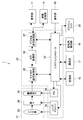
- FIG. 4 is a functional block diagram showing the internal configuration of the digital camera 100.
- the digital camera 100 includes an imaging unit 21, a control unit 31, a display unit 11, an image storage unit 14, an operation unit 15, a storage unit 16, a communication unit 17, and a rotation angle.
- a detection unit 18 and a flashlight 22 are provided.
- the imaging unit 21 includes a lens system 23, a diaphragm 24, and an imaging element 25.
- the control unit 31 includes a system controller 32, a lens driver 33, a timing generator (TG) 34, an analog signal processing unit 35, an A / D conversion unit 36, and a digital signal processing unit 37.
- TG timing generator
- the lens system 23 includes various lenses such as a zoom lens and a focus lens, and the subject light is imaged on the exposure surface of the image sensor 25 by these lenses.
- the diaphragm 24 is configured to be able to mechanically adjust the amount of subject light by adjusting the opening degree.
- the diaphragm 24 is disposed behind the lens system 23, but the diaphragm 24 is disposed in the optical path inside the lens system 23 (for example, between the zoom lens and the focus lens). It may be.
- the lens driver 33 controls the positions of the zoom lens and the focus lens and controls the opening degree of the diaphragm 24 according to an instruction from the system controller 32.
- the image sensor 25 is configured by a CMOS (Complementary Metal Oxide Semiconductor) sensor, a CCD (Charge Coupled Device) sensor, or the like.
- the image sensor 25 has a plurality of pixels (R pixel, G pixel, and B pixel). The three primary colors obtained by converting subject light incident on the exposure surface into an electronic signal by photoelectric conversion for each pixel.
- the signals (R, G, B) are output to the analog signal processing unit 35 as analog image data.
- the timing generator 34 (TG) generates a drive pulse necessary for driving the image sensor 25 in accordance with an instruction from the system controller 32 and supplies the drive pulse to the image sensor 25.
- the image pickup device 25 is driven by the timing generator 34 to pick up a subject image, and the subject image is acquired.
- the exposure time is controlled by adjusting the shutter speed of the image sensor 25 by the timing generator 34.
- the analog signal processing unit 35 executes CDS processing (CDS: Correlated Double Sampling), gain processing, and the like on the image signal output from the image sensor 25.
- CDS processing CDS: Correlated Double Sampling
- gain processing and the like on the image signal output from the image sensor 25.
- the A / D conversion unit 36 converts the analog image data output from the analog signal processing unit 35 into digital image data, and outputs the digital image data to the digital signal processing unit 37.
- the digital signal processing unit 37 is configured by, for example, a DSP (digital signal processor).
- the digital signal processing unit 37 performs various digital signals such as noise removal processing, white balance adjustment processing, color correction processing, edge enhancement processing, and gamma correction processing on the digital image data output from the A / D conversion unit 36. Execute the process. Then, the digital signal processing unit 37 outputs the image data subjected to these processes to the display unit 11.
- the digital signal processing unit 37 outputs the image data subjected to the above processing to the image storage unit 14 in accordance with the imaging timing.
- the digital signal processing unit 37 is a process for causing the display unit 11 to display the imaging guidance 1 (see FIG. 9) used when taking a selfie in response to an instruction from the system controller 32 in the selfie mode. Execute.
- a live view image, a playback image, a menu screen, and the like are displayed.
- the live view image is an image displayed on the display unit 11 so that the user can confirm the angle of view.
- the live view image is displayed on the screen by displaying the image data output from the digital signal processing unit 37 in real time.
- the reproduced image is an image displayed on the display unit 11 so that the user can confirm the captured still image.
- the reproduced image is displayed on the screen by reading and displaying the image stored in the image storage unit 14 as a still image.
- the menu screen is displayed on the screen for the user to set various parameters relating to imaging.
- the user can set, for example, zoom ratio, focus position, aperture 24 aperture, shutter speed, brightness, white balance, flash light 22 ON / OFF, and the like on the menu screen.
- the image storage unit 14 stores image data output from the digital signal processing unit 37 and metadata related to the image data (for example, date and time when the image data was acquired).
- the image storage unit 14 is configured by, for example, a semiconductor memory, an optical disk, an HD (hard disc), and the like.
- the image storage unit 14 may be fixed inside the digital camera 100 or may be configured to be detachable from the digital camera 100.
- the system controller 32 is configured by, for example, a CPU (Central Processing Unit) and the like, and comprehensively controls each unit of the digital camera 100. Specific processing of the system controller 32 will be described in detail later in the operation description column.
- a CPU Central Processing Unit
- the storage unit 16 includes various programs necessary for the processing of the control unit 31 and a non-volatile memory (for example, ROM (Read Only Memory)) in which various types of data are fixedly stored.
- the storage unit 16 also includes a volatile memory (for example, RAM (Random Access Memory)) used as a work area of the system controller 32.
- the program may be read from a portable recording medium such as an optical disk or a semiconductor memory, or may be downloaded from a server device on a network.
- the communication unit 17 has a wireless LAN function (for example, Wi-fi: wireless fidelity).
- the digital camera 100 can transmit and receive information to and from other devices having a wireless LAN function using the wireless LAN function of the communication unit 17.
- the rotation angle detector 18 detects the rotation angle of the rotating body 20 with respect to the digital camera body 10 and outputs the detected rotation angle to the system controller 32.
- the rotation angle detector 18 is constituted by, for example, a rotary encoder.
- the rotation angle is set to the reference (0 °) when the display unit 11 and the imaging unit 21 are arranged on the opposite side (see FIGS. 1 and 2), and the display unit 11 and the imaging unit 21 are the same.
- the state arranged on the side (see FIG. 3) is set to 180 °.
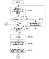
- FIG. 5 and 6 are flowcharts showing processing of the digital camera 100 according to the first embodiment.
- the system controller 32 sets the imaging mode to either the standard imaging mode or the self-portrait mode based on the information on the rotation angle detected by the rotation angle detection unit 18 (step 101). ).
- the system controller 32 provides information on the rotation angle from the rotation angle detection unit 18 (0 °). Based on the above, the imaging mode is set to the standard imaging mode. On the other hand, when the display unit 11 and the imaging unit 21 are disposed on the same side (see FIG. 3), the system controller 32 performs imaging based on the rotation angle information (180 °) from the rotation angle detection unit 18. Set the mode to selfie mode.
- the system controller 32 determines whether or not the current imaging mode is the self-shooting mode (step 102).
- the current imaging mode is not the self-portrait mode (NO in step 102)
- processing according to the standard imaging mode is executed (step 103).
- the image data captured by the image sensor 25 is processed by the analog signal processing unit 35, the A / D conversion unit 36, and the digital signal processing unit 37 and displayed on the display unit 11 as a live view image.
- the user adjusts the angle of view while confirming the live view image, and presses the shutter button 13.
- the system controller 32 instructs the digital signal processing unit 37 to output the image data to the image storage unit 14 at the timing when the shutter button 13 is pressed.
- the image storage unit 14 stores the image data output from the digital signal processing unit 37 as a still image. In the standard imaging mode, a still image is captured in this way.
- imaging of a still image refers to any image data acquired from the image capturing unit 21 and used as a live view image, such as the shutter button 13 or the image data. It means that it is specified in response to an operation on the objects 2, 3, 4 (see FIG. 9) on the display unit 11.
- imaging guidance 1 when the current imaging mode is the standard imaging mode, unlike the case where the current mode is the self-portrait mode, imaging guidance 1 (see FIG. 9) described later is displayed on the screen. Is not displayed. However, even in the standard imaging mode, imaging guidance 1 described later may be displayed on the screen, and imaging may be performed in response to a user operation on the imaging guidance 1.
- step 102 when the current mode is the self-portrait mode (YES in step 102), the system controller 32 executes the processing after step 104.
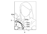
- FIG. 7 shows a state where the user sets the digital camera 100 to the self-shooting mode and performs the self-shooting.
- a state where the user holds the digital camera 100 in the left hand and takes an image of himself / herself from diagonally above in front of the user is shown.
- the subject is only one user.
- the user and several friends can be the subject.
- the system controller 32 determines whether a touch operation (predetermined user operation) on the screen of the display unit 11 has been detected by the touch sensor 12 (step 104).
- the image data captured by the image sensor 25 is processed by the analog signal processing unit 35, the A / D conversion unit 36, and the digital signal processing unit 37, as in the standard imaging mode. It is displayed on the display unit 11 as a live view image. Accordingly, even in the self-portrait mode, the user can adjust the angle of view while checking the live view image.
- Step 104 the system controller 32 returns to Step 101, and sets the imaging mode to the standard imaging mode or to the own imaging mode based on the rotation angle information detected by the rotation angle detection unit 18. Set to one of the shooting modes.
- the system controller 32 focuses the image on the subject in the live view image corresponding to the position where the touch operation is detected. (Focus lens position) is controlled (step 105).
- step 105 the system controller 32 executes AF processing (AF: Auto Focus).
- AF processing a contrast AF method is typically used, but a phase difference AF method may be used.
- phase difference AF method is used, a mirror and a focus detection sensor are added to the digital camera 100.
- the system controller 32 next sets the touched position as a reference point (step 106). Then, using the reference point as a reference, an instruction is issued to the digital signal processing unit 37 so that the imaging guidance 1 for taking a selfie is displayed on the screen (step 107). As a result, the imaging guidance 1 is displayed superimposed on the live view image on the screen of the display unit 11.
- the display process of the imaging guidance 1 is executed after the AF process, but the display process of the imaging guidance 1 may be executed in parallel with the AF process.
- FIG. 9 is a diagram illustrating an example of the imaging guidance 1 displayed in a superimposed manner on the live view image.
- the imaging guidance 1 includes a shutter object 2 (first object), five timer objects 3 (second object, third object), and a continuous shooting object 4 (fourth object).
- the object is a user interface displayed on the screen, and includes, for example, a figure, a line segment, an icon, a character, and the like. Further, the object is not limited to a visually recognizable object. For example, the object may be set as a predetermined area on the screen where a specific display is not performed.
- these objects 2, 3, and 4 are arranged on the circumference centered on the reference point.
- the 12 o'clock direction on the circumference is 0 ° and the angle increases clockwise.
- the shutter object 2 is an object for performing imaging with the immediate shutter function.
- the shutter object 2 is disposed at a position of 0 ° (position at 12 o'clock) on the circumference of the imaging guidance 1.
- a camera figure is adopted as the shutter object 2 figure.
- the figure of the shutter object 2 may be any figure as long as the user can easily recall the immediate shutter function.
- the five timer objects 3 are objects for performing imaging with the self-timer function.
- the five timer objects 3 are arranged at equal intervals (36 ° intervals) from the upper right position to the lower side on the circumference of the imaging guidance 1.
- the five timer objects 3 are assigned with different count periods, and the count periods are 1 second, 2 seconds, 3 seconds, 4 seconds, 5 seconds (first time, second time) in order clockwise. Time).
- a black circle is adopted as the figure of the four timer objects 3 corresponding to the counting period of 1 to 4 seconds, and the timer object 3 corresponding to the counting period of 5 seconds (arranged at the 6 o'clock position).
- the figure of the stopwatch is adopted as the figure of the (object).
- the figure of the timer object 3 may be any figure as long as the user can easily recall the self-timer function.
- each timer object 3 may be configured by a graphic representing the number of seconds.
- the first, second, third, fourth, and fifth timer objects 3a, 3b, 3c, and 3d are sequentially turned clockwise. 3e.
- the continuous shooting object 4 is an object for performing imaging using a continuous shooting function (a function for performing continuous imaging at predetermined intervals).
- the continuous shooting object 4 is arranged at a position of 270 ° (position at 9 o'clock) on the circumference of the imaging guidance 1.
- a figure in which a quadrangle (a figure pronounced of a photograph) is superimposed is adopted as the figure of the continuous shooting object 4.
- the figure of the continuous shooting object 4 may be any figure as long as the user can easily recall the continuous shooting function.
- arrow figures are arranged from the center of the imaging guidance 1 in four directions, up, down, left and right.
- This arrow graphic is a graphic for guiding the user to slide the finger in that direction.
- system controller 32 upon displaying imaging guidance 1 on the screen, system controller 32 next determines whether or not the touch operation has been released based on the output from touch sensor 12 (step 108). .
- Step 109 the system controller 32 instructs the digital signal processing unit 37 to delete the imaging guidance 1 from the screen (Step 109). Thereby, when the user lifts his / her finger from the screen, the imaging guidance 1 is erased from the screen.
- the user can display the imaging guidance 1 at an arbitrary position on the screen by touching the screen, and can erase the imaging guidance 1 from the screen by canceling the touch operation. That is, the user can display the imaging guidance 1 on the screen as necessary.
- the system controller 32 returns to step 104 and determines again whether a touch operation has been detected.
- the system controller 32 determines whether or not a flick operation has been detected on the screen based on the output from the touch sensor 12 (step 110).
- the flick operation means an operation in which the user slides his / her finger on the screen and gradually releases the finger from the screen without losing the momentum of the slid finger.
- step 110 the system controller 32 returns to step 108 and determines again whether the touch operation has been released.
- the system controller 32 deletes the imaging guidance 1 (step 111). Thereafter, the system controller 32 determines whether the flick operation is a flick operation on the shutter object 2 according to the direction of the flick operation (step 112).
- step 112 the system controller 32 determines that the flick operation on the shutter object 2 is detected when the direction of the flick operation is the direction of 0 ° (the direction at 12 o'clock). Note that the direction of the flick operation does not have to be strictly 0 °, and there is some margin in the direction of the flick operation. In this embodiment, when the direction of the flick operation is within a range of ⁇ 18 ° with respect to the direction of 0 °, it is determined that the flick operation on the shutter object 2 has been detected.
- the system controller 32 performs imaging using the immediate shutter function (step 113).
- imaging using the immediate shutter function the system controller 32 issues an instruction to the digital signal processing unit 37 in accordance with the timing when the flick operation is detected, and causes the digital signal processing unit 37 to output image data to the image storage unit 14.
- the image storage unit 14 stores the image data output from the digital signal processing unit 37 as still image data.
- the user can perform imaging by the immediate shutter function by touching the screen with a finger and performing a flick operation in a predetermined direction (0 ° ⁇ 18 °) without releasing the finger from the screen. Can do.
- the hand holding the digital camera 100 may shake, and the angle of view adjusted by the user while viewing the live view image may shift.
- the system controller 32 is not immediately after the flick operation is detected in the imaging by the immediate shutter function, but for a predetermined time from the time when the flick operation is detected (the shortest count in the self timer function). Imaging may be performed after elapse of a time (for example, about 0.5 seconds) shorter than the period (1 second).
- the system controller 32 When imaging is performed using the immediate shutter function, the system controller 32 returns to step 104 and determines again whether a touch operation has been detected.
- the system controller 32 determines whether the flick operation is a flick operation on the timer object 3 (step 114).
- step 114 the system controller 32 performs the flick operation in the order of 36 ° ⁇ 16 °, 72 ° ⁇ 16 °, 108 ° ⁇ 16 °, 144 ° ⁇ 16 °, and 180 ° ⁇ 16 °, respectively.
- the system controller 32 When a flick operation on the first, second, third, fourth, and fifth timer objects 3a, 3b, 3c, 3d, and 3e is detected (YES in step 114), the system controller 32 performs the flick operation. Imaging is performed 1 second, 2 seconds, 3 seconds, 4 seconds, and 5 seconds after detection. That is, the system controller 32 performs imaging using the self-timer function (step 115).
- the system controller 32 In imaging using the self-timer function, when a flick operation is detected, the system controller 32 sets a count value of the number of seconds corresponding to the timer object 3 that is the target of the flick operation in a timer (not shown). Then, the system controller 32 starts a countdown (may be counted up) by a timer.
- FIG. 10 is a diagram illustrating an example of the countdown guidance 5.
- FIG. 10 shows an example of the countdown guidance 5 displayed on the screen when the flick operation on the fifth timer object 3e is detected and the countdown for 5 seconds is executed.
- the countdown guidance 5 is arranged at a position based on the position where the touch operation is detected.
- the countdown guidance 5 has a number object 6 indicating the remaining number of seconds until imaging is performed at the center position.
- the countdown guidance 5 has a countdown object 7 on the circumference of a circle centered on the reference point.
- the countdown object 7 is arranged at a position corresponding to the arrangement position of the shutter object 2 and the timer object 3 in the imaging guidance 1.
- the countdown object 7 is a white circle, but the countdown object 7 may be any shape.
- the display of the countdown object 7 is changed one by one counterclockwise every time the countdown advances 1 second.
- FIG. 10 shows an example in which a white circle shape changes to a translucent white circle each time the countdown advances by 1 second.
- the method of changing the display can be changed as appropriate. For example, a method may be used in which the countdown object 7 corresponding to the remaining number of seconds until imaging is performed is highlighted, and the highlighting is terminated one by one every time the countdown advances by 1 second.
- a stopwatch graphic is displayed at the upper left position of the screen to indicate to the user that the timer is being down.
- the system controller 32 issues an instruction to the digital signal processing unit 37 in accordance with this timing, and causes the digital signal processing unit 37 to output image data to the image storage unit 14.
- the image storage unit 14 stores the image data output from the digital signal processing unit 37 as still image data.
- the user can touch the screen with a finger and release the finger from the screen in a predetermined direction (36 ° ⁇ 16 °, 72 ° ⁇ 16 °, 108 ° ⁇ 16 °, 144 ° ⁇ 16 °). , 180 ° ⁇ 16 °), a self-timer function can be used for imaging. At this time, the user can arbitrarily select a counting period by the timer according to the direction of the flick operation.
- the system controller 32 When imaging by the self-timer function is performed, the system controller 32 thereafter returns to step 104 and determines again whether the touch operation has been detected.
- the system controller 32 determines whether the flick operation is a flick operation on the continuous shooting object 4 (step 116).
- step 116 the system controller 32 determines that the flick operation on the continuous shooting object 4 has been detected when the direction of the flick operation is within a range of 270 ° ⁇ 16 °.
- the system controller 32 performs imaging using the continuous shooting function (step 117).
- the system controller 32 first issues an instruction to the digital signal processing unit 37 at the timing when the flick operation is detected, and outputs image data from the digital signal processing unit 37 to the image storage unit 14. Let The image storage unit 14 stores the image data output from the digital signal processing unit 37 as still image data. Thereby, the first still image data is acquired.
- imaging in order to eliminate the influence of camera shake, it is not performed immediately after the flick operation is detected, but for a short time (for example, 0.5 seconds) from the time when the flick operation is detected. About) imaging may be performed after elapse. Alternatively, imaging may be performed after a time of about 1 to 5 seconds has passed, as in the case of imaging with the self-timer function.
- the system controller 32 sets a predetermined count value (for example, about 3 to 5 seconds) in the timer, and executes countdown (may be counted up) by the timer. Then, the system controller 32 issues an instruction to the digital signal processing unit 37 at the timing when the countdown by the timer ends, and causes the digital signal processing unit 37 to output image data to the image storage unit 14.
- the image storage unit 14 stores the image data output from the digital signal processing unit 37 as still image data, thereby acquiring the second still image data.
- the third and subsequent still images are captured in the same manner as the second still image.
- imaging is continuously performed at a predetermined time interval (first time interval: 3 seconds to 5 seconds).
- first time interval 3 seconds to 5 seconds.
- the system controller 32 ends imaging by the continuous shooting function, and returns to step 104 again.
- the user can perform imaging by the continuous shooting function by performing a flick operation in a predetermined direction (270 ° ⁇ 16 °) without touching the screen with a finger and releasing the finger from the screen. it can.
- the period from when the imaging is performed until the next imaging is set to a relatively long period of about 3 to 5 seconds. For this reason, the user can change the facial expression and posing during this period.
- a facial expression / posing guidance for guiding at least one of them to the user may be displayed on the screen.
- This facial expression / pose guidance is an image of a character (or an image of an actual person) with various facial expressions and various poses. This facial expression / pose guidance is displayed superimposed on the live view image at the end position on the screen, for example.
- the facial expression / pose guidance is a facial expression or outline of a characteristic part in posing.
- the facial expression / pose guidance is displayed at a corresponding position in the subject on the screen (for example, the mouth position in the live view image when the mouth has a feature in the facial expression).
- facial expressions examples include “duck mouth” (a duck-like mouth shape that slightly projects the upper lip while spreading the mouth horizontally), “Chun face” (a sparrow that slightly opens its mouth and slightly projects its lips) Mouth shape like), “Tehepero” (an expression that puts out the tongue with an embarrassing expression (failed to something)), “a troubled face”, “a surprised face” and so on.
- poses examples include “V-sign”, “salute”, “pause with palm on cheek”, “quiet pose” (pose with index finger on nose), “cat pose” (see palm) For example, a pose in which a finger is lightly folded and the palm is directed toward the imaging unit 21). It should be noted that facial expression and posing may be combined (for example, V-sign etc. while duck mouth).
- the facial expression / pose guidance is sequentially switched to a different facial expression / pose every time an image is taken.
- the user can acquire various facial expressions and posing images without wondering what facial expression or posing is to be performed next.
- the facial expression / pose guidance may be displayed on the screen not only with the continuous shooting function but also with the above-described self-timer function. Further, in the imaging by the continuous shooting function, the countdown guidance 5 (see FIG. 10) may be displayed on the screen (alone or together with the facial expression / pose guidance).
- the count period by the timer is set in advance in the imaging by the continuous shooting function.
- the count period in the imaging by the continuous shooting function may be determined according to the direction of the flick operation similarly to the count period by the self timer function. That is, the continuous shooting function and the self-timer function (every hour) may be combined.
- a plurality of continuous shooting / timer objects are arranged at equal intervals (for example, 36 ° intervals) on the circumference of the imaging guidance 1 (for example, the left half). .
- These continuous shooting / timer objects are assigned different count periods (first time interval and second time interval).
- the system controller 32 determines the counting period until the next imaging is performed. Set to the count period corresponding to the object.
- the system controller 32 performs imaging by the continuous shooting function at intervals of 5 seconds (for the first imaging, imaging is performed immediately. Imaging may be performed after a count period of 5 seconds has elapsed). As a result, the user can arbitrarily set the interval in imaging by the continuous shooting function according to the direction of the flick operation.
- the number of still images acquired by the continuous shooting function is determined in advance.
- the number of still images may be determined according to the direction of the flick operation.
- a plurality of continuous shooting / number of objects assigned different numbers are arranged at equal intervals (for example, 36 ° intervals).
- the system controller 32 obtains the number of still images corresponding to the continuous shooting / number of objects.
- the imaging is performed by the continuous shooting function. Thereby, the user can arbitrarily set the number of still images acquired in the imaging by the continuous shooting function according to the direction of the flick operation.
- the user can perform imaging (self-portrait) using the immediate shutter function by performing a flick operation on the shutter object 2 among the objects displayed on the screen. it can.
- the user can perform imaging (self-portrait) using the self-timer function by performing a flick operation on the timer object 3.
- the user when taking a self-portrait, the user can intuitively select whether to perform imaging using the immediate shutter function or to perform imaging using the self-timer function with immediacy. Furthermore, in the present embodiment, different count periods are assigned to the plurality of timer objects 3, respectively. For this reason, the user can arbitrarily select the count period by the self-timer function according to the direction of the flick operation.
- the user can freely select whether to perform imaging using the immediate shutter function or the self-timer function every time the imaging is performed, and each time the imaging is performed, the user can use the self-timer function.
- the count period can be arbitrarily selected.
- the user can take a selfie while having fun using the digital camera 100 according to the present embodiment, and the user experience is improved.
- the digital camera 100 according to the present embodiment has a simple operation when taking a self-portrait, and is also suitable for taking a self-portrait while walking.
- the imaging guidance 1 is displayed with the position where the touch operation is detected on the screen as a reference point. Accordingly, when the end position on the screen is touched, it may be difficult to display the imaging guidance 1 in a circular shape.
- processing such as changing the display mode of the imaging guidance 1 is executed according to the position (reference point position) where the touch operation is detected.
- FIG. 11 shows a state on the screen when the user performs a touch operation near the left end in the screen.
- a touch operation is performed near the left end
- a reference point is set at the touched position
- the imaging guidance 1 is displayed at a position corresponding to the reference point.
- This imaging guidance 1 has a shutter object 2, five timer objects 3, and a continuous shooting object 4 on the circumference of the right half (on the circumference of the arc).
- the shutter object 2 is arranged at the 0 ° position (12 o'clock position), and the five timer objects 3 are arranged at equal intervals from the upper right to the lower left. Further, the shutter object 2 is disposed at a position of 180 ° (position at 6 o'clock).
- the center of the arc in which each object is arranged coincides with the reference point (position where the touch operation is performed).
- the center of the arc does not necessarily coincide with the reference point, and the center of the arc may be located outside the screen, for example. This is the same in FIGS. 12 and 13 described later.
- FIG. 12 shows a state on the screen when the user performs a touch operation near the upper end in the screen.
- the shutter object 2 when the vicinity of the upper end is touched, the shutter object 2, the five timer objects 3, and the continuous shooting object 4 are arranged on the circumference of the lower half (around the arc).
- the shutter object 2 is arranged at a 90 ° position (3 o'clock position), and five timer objects 3 are arranged at equal intervals from the lower right to the lower left.
- the shutter object 2 is arranged at a position of 270 ° (position at 9 o'clock).
- FIG. 13 shows a state on the screen when the user performs a touch operation near the lower left end in the screen.
- the shutter object 2 when a touch operation is performed near the lower left end, the shutter object 2, the five timer objects 3, and the continuous shooting object 4 are arranged on the circumference of the upper right quarter (on the circumference of the arc). Is done.
- the shutter object 2 is arranged at a position of 0 ° (position at 12 o'clock), and the five timer objects 3 are arranged at equal intervals on the upper right circle. Further, the shutter object 2 is arranged at a 90 ° position (position at 3 o'clock).
- FIG. 9 when FIG. 9 is compared with FIGS. 11 to 13, although the relative positions of the shutter object 2, the five timer objects 3, and the continuous shooting object 4 have changed, their relative positions are It is maintained as much as possible. Also, the interval between the five timer objects 3 is maintained as much as possible. For this reason, the user can perform an operation on each object with a certain operation feeling regardless of the position of the touch operation.
- Another example of changing the display mode of the imaging guidance 1 is a method of changing the overall size of the imaging guidance 1 according to the position of the touch operation. In this case, the closer the position of the touch operation is to the end, the smaller the overall size of the imaging guidance 1 (the direction in which each object is arranged with respect to the reference point does not change).
- the imaging guidance 1 Other functions that can be assigned in the imaging guidance 1 include a flashlight imaging function.
- the flashlight object (sixth object) is arranged on the circumference of the imaging guidance 1 (for example, at a position of 270 °).
- the system controller 32 causes the imaging unit 21 to perform imaging while making the flashlight 22 emit light (immediate shutter).
- the flashlight imaging function can be combined with the self-timer function (every hour).
- a plurality of flash timer objects are arranged at equal intervals on the circumference of the imaging guidance 1 (for example, the left half). Different count periods are set for the plurality of flash timer objects.
- a count period of seconds corresponding to the flash timer object subjected to the flick operation is set, and flashlight imaging is performed at the end of the cant down.
- the flashlight imaging function and the continuous shooting function can be combined.
- the flash / continuous shooting object is arranged on the circumference of the imaging guidance 1 (for example, at a position of 270 °).
- flashlight imaging is continuously performed at a predetermined time interval (3 to 5 seconds).
- the flashlight imaging function, the continuous shooting function, and the self-timer function may be combined.
- a plurality of flash, continuous shooting, and timer objects are arranged at equal intervals on the circumference of the imaging guidance 1 (for example, the left half).
- a different count period is set for each of the plurality of flash, continuous shooting, and timer objects.
- flashlight imaging is performed for each count period corresponding to the flash, continuous shooting, and timer object that are the targets of the flick operation.
- Other functions that can be assigned in the imaging guidance 1 include a shutter speed adjustment function, a zoom ratio adjustment function, a focus position adjustment function, an aperture opening adjustment function, a brightness adjustment function, a white balance adjustment function, and the like. It is done.
- the shutter speed adjustment function will be described representatively.
- a plurality of shutter speed objects respectively corresponding to the respective shutter speeds are arranged at equal intervals on the circumference of the imaging guidance 1 (for example, the left half).
- the shutter speed is set to a value corresponding to the shutter speed object that is the target of the flick operation.
- the user touches the screen to display the imaging guidance 1 and performs a flick operation on any shutter speed object among the plurality of shutter speed objects. Thereby, the user can set the shutter speed to an arbitrary shutter speed. Thereafter, the user touches the screen again to display the imaging guidance 1 and performs a flick operation on the shutter object 2 (or the timer object 3, the continuous shooting object 4, etc.), so that the shutter speed is set. Imaging can be performed.
- the zoom rate adjustment function, the focus position adjustment function, the aperture opening adjustment function, the brightness adjustment function, and the white balance adjustment function can be applied in the same manner as the shutter speed adjustment function, and thus will be described in detail. Is omitted.
- imaging guidance 1 since various functions can be assigned in this way in the imaging guidance 1, it is expected that an arbitrary function cannot be arranged with only one imaging guidance 1. Accordingly, a plurality of imaging guidances 1 to which different functions are assigned may be prepared. In this case, different imaging guidances 1 may be displayed on the screen according to the user operation method.
- the first imaging guidance 1 is displayed on the screen when a touch operation or a tap operation (an operation to release the finger from the screen immediately after touching the screen) is detected. Then, when a double tap operation (operation for repeating the tap operation twice) is detected, the second imaging guidance 1 is displayed on the screen. Similarly, when an n-tap operation is detected, the n-th imaging guidance 1 is displayed on the screen.
- At least an immediate shutter function and a self-timer function are assigned to the first imaging guidance 1 among the plurality of imaging guidances 1.
- the continuous shooting function and the flashlight imaging function (or a combination of at least two of the self-timer function, the continuous shooting function, and the flashlight imaging function) are functions directly related to the act of performing imaging. .
- these functions are preferentially assigned to the first imaging guidance 1.
- the function is assigned to the second imaging guidance 1, the third imaging guidance 1,.
- the shutter speed adjustment function, the zoom ratio adjustment function, the focus position adjustment function, the aperture opening adjustment function, the brightness adjustment function, and the white balance adjustment function are not functions directly related to the act of imaging, This function is indirectly related to imaging.
- the various adjustment functions described above have lower priority than functions directly related to imaging, and typically are assigned to the imaging guidance 1 after functions directly related to imaging are assigned. It is done. For example, when the assignment of the function directly related to imaging is completed in the third imaging guidance 1, the above-described adjustment function is assigned in the fourth imaging guidance 1, the fifth imaging guidance 1,. .
- Imaging guidance 1 Display and erase timing of imaging guidance 1
- the imaging guidance 1 may not be erased even if the touch operation is released, and the imaging guidance 1 may be erased from the screen when a position other than the position where the imaging guidance 1 is displayed is touched.
- the imaging guidance 1 may always be displayed at a predetermined position on the screen (for example, the position of the edge of the screen) in the self-portrait mode.
- the imaging guidance 1 is displayed based on the position where the touch operation is detected.
- the imaging guidance 1 may be displayed at a position unrelated to the position where the touch operation is detected.
- the imaging guidance 1 may be displayed at a preset position such as the center of the screen or the position of the edge of the screen regardless of the position where the touch operation is detected. In this case, the imaging guidance 1 is not erased from the screen even if the touch operation is released.
- the flick operation in the direction in which each object is arranged has been described as an example of the user operation on each object.
- the operation on each object is not limited to the flick operation.
- this user operation may be an operation in which a finger is continuously slid from a reference point to a position where each object is arranged.
- the user operation for each object may be a touch operation, a tap operation, or a double tap operation for each object.
- the imaging guidance is always displayed on the screen, or is erased from the screen when a position other than the position where the imaging guidance 1 is displayed is touched (the operation for each object is performed). If not).
- the user operation on each object may be an operation of sliding a finger along the circumference and releasing (or stopping) the finger at a position where an arbitrary object is displayed.
- the user slides his / her finger clockwise along the circumference to display an arbitrary timer object 3. You may release your finger at the position.
- the user touches the position where the fifth timer object 3e is displayed, the user slides his / her finger counterclockwise along the circumference and moves the finger at the position where the arbitrary timer object 3 is displayed. May be released.
- the imaging guidance 1 is always displayed on the screen, or is deleted from the screen when a position other than the position where the imaging guidance 1 is displayed is touched (for each object). If there was no operation).
- the user operation on each object may be a combination of an operation of sliding a finger from the reference point to a position where the object is arranged and an operation of sliding the finger along the circumference.
- the user slides his / her finger from the reference point to a position where the shutter object 2 is displayed, and then slides his / her finger clockwise along the circumference.
- You may perform operation which lifts a finger
- the user slides the finger from the reference point to the position where the fifth timer object 3e is displayed, and then slides the finger counterclockwise along the circumference, so that an arbitrary timer object 3 is displayed. You may perform operation which lifts a finger
- any of the various examples described above may be used as the display timing and the erasing timing of the imaging guidance 1.
- gesture operations for displaying (calling) the imaging guidance 1 on the screen include an operation of drawing a circle with a finger and an operation of repeatedly opening a closed hand.
- the gesture operation may be an operation that repeats blinking quickly.
- gesture operations for objects include a swinging arm from the reference point in the direction in which an arbitrary object is placed, or a circle with your finger by aligning your finger to the position where the arbitrary object is displayed. For example, drawing.
- this gesture operation may be an operation of turning a line of sight in a direction in which an arbitrary object is displayed.
- gesture operations For example, the user shakes his / her arm, moves the fingertip from the reference point to the position where the shutter object 2 is displayed, and then moves the fingertip clockwise along the circumference to move any timer object 3.
- a circle may be drawn with a finger at a position where is displayed.
- the system controller 32 may determine whether the gesture operation has been performed based on the image captured by the imaging unit 21.
- Remote control It is also possible to take a selfie by placing the digital camera 100 at a predetermined position and performing remote control with another device.
- a smartphone imaging control apparatus
- This smartphone can transmit and receive information to and from the digital camera 100 by a wireless LAN function (for example, Wi-fi) by the communication unit.
- a wireless LAN function for example, Wi-fi
- the digital camera 100 transmits the image data captured by the imaging unit 21 to the smartphone via the communication unit 17.
- the smartphone displays the received image data as a live view image on the screen of the display unit.
- the smartphone displays the imaging guidance 1 superimposed on the live view image. The user can take a selfie by operating the imaging guidance 1 displayed on the screen of the smartphone.
- the smartphone uses the digital camera 100 to perform imaging using the immediate shutter function, the self-timer function, and the continuous shooting function.
- the digital camera 100 performs imaging with an immediate shutter function, a self-timer function, and a continuous shooting function.
- the digital camera 100 when the digital camera 100 is placed at a predetermined position and self-portrait is performed by gesture operation or remote operation, it is not limited to imaging by one user or several people including the user, but by a large number of people including the user in a sightseeing spot or the like It is also possible to take an image of the group.
- imaging control device In the above description, the digital camera 100 and the smartphone have been described as examples of the imaging control device, but the imaging control device is not limited thereto.
- the imaging control device may be a PC (Personal Computer), a television device, a portable game machine, a game machine, or the like.
- An imaging guidance including a first object, a second object, and a third object is displayed on a screen of a display unit, and the first object, the second object, and the third object are displayed. It is determined whether a user operation is detected. When a user operation on the first object is detected, the imaging unit performs imaging. When a user operation on the second object is detected, the user operation is detected. When a first operation has been performed and the imaging unit performs imaging, and when a user operation on the third object is detected, the first time after the user operation on the third object is detected.
- An imaging control apparatus comprising: a control unit that causes the imaging unit to perform imaging after the elapse of a second time different from the first time.
- the imaging control device determines that a user operation on the first object is detected when a user operation in a direction in which the first object is arranged from the reference point is detected, and the control unit determines from the reference point that the first operation is performed.
- a user operation in the direction in which the second object is arranged it is determined that a user operation on the second object has been detected, and in the direction in which the third object is arranged from the reference point.
- An imaging control device that determines that a user operation on the third object has been detected when a user operation is detected.
- the control unit determines whether a predetermined user operation is detected, and displays the imaging guidance on a screen when the predetermined user operation is detected.
- the imaging control device according to (4) above When the predetermined user operation is detected, the control unit determines a position in the screen where the predetermined user operation is detected, and sets the reference point at a position where the predetermined user operation is detected. Set the imaging control device.
- the imaging control device displays the image imaged by the said imaging part on the said screen as a live view image, and superimposes and displays the said imaging guidance on the said live view image.
- the imaging control device controls the imaging unit to focus on the position of the subject in the live view image corresponding to the position in the screen where the predetermined user operation is detected.
- the imaging guidance has a fourth object, The control unit determines detection of a user operation on the fourth object, and causes the imaging unit to continuously perform imaging at a first time interval when an operation on the fourth object is detected. Control device.
- the control unit displays an expression / pose guidance on the screen for guiding at least one of facial expression and posing to the user within the first time interval.
- the imaging guidance has a fifth object, The control unit determines the detection of a user operation on the fifth object, and when a user operation on the fifth object is detected, the imaging unit is at a second time interval different from the first time interval.
- An imaging control device that allows continuous imaging.
- the imaging control device according to any one of (1) to (11) above, The imaging guidance has a sixth object, The control unit determines whether or not a user operation on the sixth object is detected.
- the control unit When an operation on the sixth object is detected, the control unit causes the imaging unit to perform imaging while emitting a flashlight.
- Control device. (13) Display imaging guidance including the first object, the second object, and the third object on the screen of the display unit; Determining the detection of a user operation on the first object, the second object and the third object; When a user operation on the first object is detected, the imaging unit performs imaging, When a user operation on the second object is detected, the imaging unit performs imaging after a first time has elapsed since the user operation was detected; When a user operation on the third object is detected, the imaging unit causes the imaging unit to take an image after a second time different from the first time since the user operation on the third object is detected.
- Imaging control device Displaying imaging guidance including a first object, a second object, and a third object on a screen of a display unit; Determining the detection of a user operation on the first object, the second object and the third object; When a user operation on the first object is detected, the imaging unit performs imaging, When a user operation on the second object is detected, causing the imaging unit to perform imaging after a first time has elapsed since the user operation was detected; When a user operation on the third object is detected, causing the imaging unit to take an image after a second time different from the first time since the user operation on the third object is detected; and A program that executes
Abstract
Description
前記制御部は、第1のオブジェクト、第2のオブジェクト、及び第3のオブジェクトを含む撮像ガイダンスを表示部の画面上に表示させ、前記第1のオブジェクト、前記第2のオブジェクト及び前記第3のオブジェクトに対するユーザ操作の検出を判断し、前記第1のオブジェクトに対するユーザ操作が検出されたとき、撮像部に撮像を行わせ、前記第2のオブジェクトへのユーザ操作が検出されたとき、ユーザ操作が検出されてから第1の時間経過後に前記撮像部に撮像を行わせ、前記第3のオブジェクトへのユーザ操作が検出されたとき、前記第3のオブジェクトへのユーザ操作が検出されてから第1時間とは異なる第2の時間経過後に撮像部に撮像を行わせる。
この場合、前記制御部は、前記第4のオブジェクトに対するユーザ操作の検出を判断し、前記第4のオブジェクトに対する操作が検出された場合、第1の時間間隔で前記撮像部に連続して撮像を行わせてもよい。
この場合、前記制御部は、前記第5のオブジェクトに対するユーザ操作の検出を判断し、前記第5のオブジェクトに対するユーザ操作が検出された場合、前記第1の時間間隔とは異なる第2の時間間隔で撮像部に連続して撮像を行わせてもよい。
この場合、前記制御部は、前記第6のオブジェクトに対するユーザ操作の検出を判断し、前記第6のオブジェクトに対する操作が検出された場合、フラッシュライトを発光させつつ前記撮像部に撮像を行わせてもよい。
前記第1のオブジェクト、前記第2のオブジェクト及び前記第3のオブジェクトに対するユーザ操作の検出が判断される。
前記第1のオブジェクトに対するユーザ操作が検出されたとき、撮像部によって撮像が行われる。
前記第2のオブジェクトへのユーザ操作が検出されたとき、ユーザ操作が検出されてから第1の時間経過後に前記撮像部によって撮像が行われる。
前記第3のオブジェクトへのユーザ操作が検出されたとき、前記第3のオブジェクトへのユーザ操作が検出されてから第1時間とは異なる第2の時間経過後に撮像部によって撮像が行われる。
第1のオブジェクト、第2のオブジェクト、及び第3のオブジェクトを含む撮像ガイダンスを表示部の画面上に表示させるステップと、
前記第1のオブジェクト、前記第2のオブジェクト及び前記第3のオブジェクトに対するユーザ操作の検出を判断するステップと、
前記第1のオブジェクトに対するユーザ操作が検出されたとき、撮像部に撮像を行わせるステップと、
前記第2のオブジェクトへのユーザ操作が検出されたとき、ユーザ操作が検出されてから第1の時間経過後に前記撮像部に撮像を行わせるステップと、
前記第3のオブジェクトへのユーザ操作が検出されたとき、前記第3のオブジェクトへのユーザ操作が検出されてから第1時間とは異なる第2の時間経過後に撮像部に撮像を行わせるステップとを実行させる。
[デジタルカメラ100の全体構成及び各部の構成]
図1は、本技術の第1実施形態に係るデジタルカメラ100の外観構成を示す正面図である。図2は、デジタルカメラ100の外観構成を示す背面図である。本実施形態に係るデジタルカメラ100(撮像制御装置)は、静止画を撮像可能なデジタルスチルカメラである。なお、このデジタルカメラ100は、静止画に加えて、動画を撮像可能なように構成することもできる。
次に、第1実施形態に係るデジタルカメラ100による処理について具体的に説明する。図5及び図6は、第1実施形態に係るデジタルカメラ100の処理を示すフローチャートである。
以上説明したように、本実施形態においては、ユーザは、画面上に表示されている各オブジェクトのうち、シャッタオブジェクト2に対するフリック操作を行うことで即時シャッタ機能による撮像(自分撮り)を行うことができる。また、ユーザは、タイマオブジェクト3に対するフリック操作を行うことで、セルフタイマ機能による撮像(自分撮り)を行うことができる。
さらに、本実施形態では、複数のタイマオブジェクト3においてそれぞれ異なるカウント期間が割り当てられている。このため、ユーザは、セルフタイマ機能によるカウント期間を、フリック操作の方向に応じて任意に選択することもできる。
次に、本技術の第2実施形態について説明する。なお、第2実施形態以降の説明では、上述の第1実施形態と同様の機能及び構成を有する各部については同一符号を付し、説明を省略又は簡略化する。
[撮像ガイダンス1に割り当てられる機能]
上述の各実施形態の説明では、撮像ガイダンス1において、即時シャッタ機能、セルフタイマ機能及び連写機能が割り当てられる場合について説明した。一方、連写機能については必ずしも割り当てられている必要はなく、省略することもできる。また、撮像ガイダンス1において、連写機能に代えて(あるいは、連写機能に加えて)、他の機能が割り当てられていてもよい。
上述の例では、タッチ操作が解除されたタイミングで、撮像ガイダンス1が画面上から消去される場合について説明した。一方、タッチ操作が解除されても撮像ガイダンス1が消去されず、撮像ガイダンス1が表示されている位置以外の位置がタッチ操作された場合に、画面上から撮像ガイダンス1が消去されてもよい。
上述の説明では、タッチ操作が検出された位置を基準として撮像ガイダンス1が表示される場合について説明した。しかしながら、撮像ガイダンス1はタッチ操作が検出された位置とは無関係な位置に表示されてもよい。例えば、撮像ガイダンス1は、タッチ操作が検出された位置に関わらず、画面の中央や、画面の端の位置など、予め設定された位置に表示されてもよい。なお、この場合、タッチ操作が解除されても撮像ガイダンス1は画面上から消去されない。
上述の例では、各オブジェクトに対するユーザ操作の一例として、各オブジェクトが配置されている方向へのフリック操作を例に挙げて説明した。一方、各オブジェクトに対する操作は、フリック操作に限られない。例えば、このユーザ操作は、基準点から各オブジェクトが配置されている位置まで指をスライドさせ続ける操作であってもよい。
上述の例では、撮像ガイダンス1を画面上に表示させる(呼び出す)ためのユーザ操作(所定のユーザ操作)、並びに、各オブジェクトに対するユーザ操作の例として、画面への操作を例に挙げて説明した。一方、画面へのユーザ操作の代わりに、画面から離れた位置でのジェスチャ操作が用いられてもよい。
デジタルカメラ100を所定の位置に置き、他の装置で遠隔制御を行うことで、自分撮りを行うことも可能である。例えば、遠隔制御を行うための他の装置として、通信部及び表示部を有するスマートフォン(撮像制御装置)を例に挙げて説明する。このスマートフォンは、通信部による無線LAN機能(例えば Wi-fi)により、デジタルカメラ100との間で情報を送受信することができる。
上述の説明では、撮像制御装置の一例としてデジタルカメラ100、スマートフォンを例に挙げて説明したが、撮像制御装置はこれに限られない。例えば、撮像制御装置は、PC(Personal Computer)、テレビジョン装置、携帯ゲーム機、ゲーム機等であっても構わない。
(1)第1のオブジェクト、第2のオブジェクト、及び第3のオブジェクトを含む撮像ガイダンスを表示部の画面上に表示させ、前記第1のオブジェクト、前記第2のオブジェクト及び前記第3のオブジェクトに対するユーザ操作作の検出を判断し、前記第1のオブジェクトに対するユーザ操作が検出されたとき、撮像部に撮像を行わせ、前記第2のオブジェクトへのユーザ操作が検出されたとき、ユーザ操作が検出されてから第1の時間経過後に前記撮像部に撮像を行わせ、前記第3のオブジェクトへのユーザ操作が検出されたとき、前記第3のオブジェクトへのユーザ操作が検出されてから第1時間とは異なる第2の時間経過後に撮像部に撮像を行わせる制御部
を具備する撮像制御装置。
(2)上記(1)に記載の撮像制御装置であって、
前記撮像ガイダンスは、前記画面内において設定された基準点に対応する円又は円弧の周上に前記第1のオブジェクト、前記第2のオブジェクト、及び前記第3のオブジェクトを有する
撮像制御装置。
(3)上記(2)に記載の撮像制御装置であって、
前記制御部は、前記基準点から第1のオブジェクトが配置されている方向へのユーザ操作が検出されたとき、前記第1のオブジェクトに対するユーザ操作が検出されたと判断し、前記基準点から前記第2のオブジェクトが配置されている方向へのユーザ操作が検出されたとき、前記第2のオブジェクトに対するユーザ操作が検出されたと判断し、前記基準点から前記第3のオブジェクトが配置されている方向へのユーザ操作が検出されたとき、前記第3のオブジェクトに対するユーザ操作が検出されたと判断する
撮像制御装置。
(4)上記(2)又は(3)に記載の撮像制御装置であって、
前記制御部は、所定のユーザ操作が検出されたどうかを判断し、前記所定のユーザ操作が検出された場合に、前記撮像ガイダンスを画面上に表示させる
撮像制御装置。
(5)上記(4)に記載の撮像制御装置であって、
前記制御部は、前記所定のユーザ操作が検出された場合に、前記所定のユーザ操作が検出された前記画面内における位置を判断し、前記所定のユーザ操作が検出された位置に前記基準点を設定する
撮像制御装置。
(6)上記(4)又は(5)に記載の撮像制御装置であって、
前記制御部は、前記所定のユーザ操作が検出された前記画面内における位置に応じて、前記撮像ガイダンスの表示態様を変化させる
撮像制御装置。
(7)上記(5)に記載の撮像制御装置であって、
前記制御部は、前記撮像部によって撮像された画像をライブビュー画像として前記画面上に表示させ、前記撮像ガイダンスを前記ライブビュー画像に重畳して表示させる
撮像制御装置。
(8)上記(7)に記載の撮像制御装置であって、
前記制御部は、前記所定のユーザ操作が検出された前記画面内における位置に対応した、前記ライブビュー画像における被写体の位置にフォーカスを合わせるように撮像部を制御する
撮像制御装置。
(9)上記(1)~(8)のうちいずれか1つに記載の撮像制御装置であって、
前記撮像ガイダンスは、第4のオブジェクトを有し、
前記制御部は、前記第4のオブジェクトに対するユーザ操作の検出を判断し、前記第4のオブジェクトに対する操作が検出された場合、第1の時間間隔で前記撮像部に連続して撮像を行わせる
撮像制御装置。
(10)上記(9)に記載の撮像制御装置において、
前記制御部は、前記第1の時間間隔内において、顔の表情及びポージングのうち少なくとも一方をユーザにガイドする表情/ポージングガイダンスを画面上に表示させる
撮像制御装置。
(11)上記(9)又は(10)に記載の撮像制御装置であって、
前記撮像ガイダンスは、第5のオブジェクトを有し、
前記制御部は、前記第5のオブジェクトに対するユーザ操作の検出を判断し、前記第5のオブジェクトに対するユーザ操作が検出された場合、前記第1の時間間隔とは異なる第2の時間間隔で撮像部に連続して撮像を行わせる
撮像制御装置。
(12)上記(1)~(11)のうちいずれか1つに記載の撮像制御装置であって、
前記撮像ガイダンスは、第6のオブジェクトを有し、
前記制御部は、前記第6のオブジェクトに対するユーザ操作が検出されたかどうかを判定し、前記第6のオブジェクトに対する操作が検出された場合、フラッシュライトを発光させつつ前記撮像部に撮像を行わせる
撮像制御装置。
(13)第1のオブジェクト、第2のオブジェクト、及び第3のオブジェクトを含む撮像ガイダンスを表示部の画面上に表示させ、
前記第1のオブジェクト、前記第2のオブジェクト及び前記第3のオブジェクトに対するユーザ操作の検出を判断し、
前記第1のオブジェクトに対するユーザ操作が検出されたとき、撮像部に撮像を行わせ、
前記第2のオブジェクトへのユーザ操作が検出されたとき、ユーザ操作が検出されてから第1の時間経過後に前記撮像部に撮像を行わせ、
前記第3のオブジェクトへのユーザ操作が検出されたとき、前記第3のオブジェクトへのユーザ操作が検出されてから第1時間とは異なる第2の時間経過後に撮像部に撮像を行わせる
撮像制御方法。
(14)撮像制御装置に、
第1のオブジェクト、第2のオブジェクト、及び第3のオブジェクトを含む撮像ガイダンスを表示部の画面上に表示させるステップと、
前記第1のオブジェクト、前記第2のオブジェクト及び前記第3のオブジェクトに対するユーザ操作の検出を判断するステップと、
前記第1のオブジェクトに対するユーザ操作が検出されたとき、撮像部に撮像を行わせ、
前記第2のオブジェクトへのユーザ操作が検出されたとき、ユーザ操作が検出されてから第1の時間経過後に前記撮像部に撮像を行わせるステップと、
前記第3のオブジェクトへのユーザ操作が検出されたとき、前記第3のオブジェクトへのユーザ操作が検出されてから第1時間とは異なる第2の時間経過後に撮像部に撮像を行わせるステップと
を実行させるプログラム。
2…シャッタオブジェクト
3…タイマオブジェクト
4…連写オブジェクト
5…カウントダウンガイダンス
6…数字オブジェクト
7…カウントダウンオブジェクト
10…デジタルカメラ本体
11…表示部
12…タッチセンサ
13…シャッタボタン
20…回転体
21…撮像部
22…フラッシュライト
31…制御部
32…システムコントローラ
100…デジタルカメラ
Claims (14)
- 表示部上に表示された第1のオブジェクトに対するユーザ操作に基づいて、撮像部に撮像を行わせる制御と、前記表示部上に表示された第2のオブジェクトに対するユーザ操作に基づいて、第1の時間経過後に前記撮像部に撮像を行わせる制御と、前記表示部に表示された第3のオブジェクトに対するユーザ操作に基づいて、前記第1時間とは異なる第2の時間経過後に撮像部に撮像を行わせる制御とを行う制御部
を具備する撮像制御装置。 - 請求項1に記載の撮像制御装置であって、
前記制御部は、前記第1のオブジェクト、前記第2のオブジェクト、及び前記第3のオブジェクトを、円又は円弧の周上に表示させる
撮像制御装置。 - 請求項2に記載の撮像制御装置であって、
前記円又は前記円弧は、前記表示部内に基準点を有し、
前記制御部は、前記基準点から、第1のオブジェクトが配置されている方向へのユーザ操作に基づいて、前記撮像部に撮像を行わせる
撮像制御装置。 - 請求項3に記載の撮像制御装置であって、
前記制御部は、所定のユーザ操作に基づいて、前記第1のオブジェクト、前記第2のオブジェクト、及び前記第3のオブジェクトを前記表示部上に表示させる
撮像制御装置。 - 請求項4に記載の撮像制御装置であって、
前記制御部は、前記所定のユーザ操作が行われた前記表示部内における位置に応じた位置に前記基準点を設定する
撮像制御装置。 - 請求項4に記載の撮像制御装置であって、
前記制御部は、前記所定のユーザ操作が行われた前記表示部内における位置に応じて、前記第1のオブジェクト、前記第2のオブジェクト、及び前記第3のオブジェクトの全体の表示態様を異なる表示態様とする
撮像制御装置。 - 請求項1に記載の撮像制御装置であって、
前記制御部は、前記撮像部によって取得された画像をライブビュー画像として前記表示部上に表示させ、かつ、前記第1のオブジェクト、前記第2のオブジェクト、及び前記第3のオブジェクトを前記ライブビュー画像と共に表示させる
撮像制御装置。 - 請求項7に記載の撮像制御装置であって、
前記制御部は、所定のユーザ操作に基づいて、前記第1のオブジェクト、前記第2のオブジェクト、及び前記第3のオブジェクトを前記表示部上に表示させ、前記所定のユーザ操作が行われた前記表示部内における位置に基づいて、前記所定のユーザ操作の位置に対応する前記ライブビュー画像における被写体の位置にフォーカスを合わせるように撮像部を制御する
撮像制御装置。 - 請求項1に記載の撮像制御装置であって、
前記制御部は、前記表示部上に表示された第4のオブジェクトに対するユーザ操作に基づいて、第1の時間間隔で前記撮像部に連続して撮像を行わせる
撮像制御装置。 - 請求項9に記載の撮像制御装置において、
前記制御部は、前記第1の時間間隔内において、顔の表情及びポージングのうち少なくとも一方をユーザにガイドするガイダンスを画面上に表示させる
撮像制御装置。 - 請求項9に記載の撮像制御装置であって、
前記制御部は、前記表示部上に表示された第5のオブジェクトに対するユーザ操作に基づいて、前記第1の時間間隔とは異なる第2の時間間隔で撮像部に連続して撮像を行わせる
撮像制御装置。 - 請求項1に記載の撮像制御装置であって、
前記制御部は、前記表示部上に表示された第6のオブジェクトに対するユーザ操作に基づいて、フラッシュライトを発光させつつ前記撮像部に撮像を行わせる
撮像制御装置。 - 表示部上に表示された第1のオブジェクトに対するユーザ操作に基づいて、撮像部に撮像を行わせ、
前記表示部上に表示された第2のオブジェクトに対するユーザ操作に基づいて、第1の時間経過後に前記撮像部に撮像を行わせ、
前記第3のオブジェクトに対するユーザ操作に基づいて、前記第1時間とは異なる第2の時間経過後に撮像部に撮像を行わせる
撮像制御方法。 - 撮像制御装置に、
前記第1のオブジェクトに対するユーザ操作に基づいて、撮像部に撮像を行わせるステップと、
前記第2のオブジェクトに対するユーザ操作に基づいて、第1の時間経過後に前記撮像部に撮像を行わせるステップと、
前記第3のオブジェクトに対するユーザ操作に基づいて、前記第1時間とは異なる第2の時間経過後に撮像部に撮像を行わせるステップと
を実行させるプログラム。
Priority Applications (5)
| Application Number | Priority Date | Filing Date | Title |
|---|---|---|---|
| CN201580035665.9A CN106576137A (zh) | 2014-07-08 | 2015-05-18 | 图像拾取控制设备、图像拾取控制方法和程序 |
| EP15818961.3A EP3151531B1 (en) | 2014-07-08 | 2015-05-18 | Image pickup control device, image pickup control method and program |
| KR1020167036728A KR20170030496A (ko) | 2014-07-08 | 2015-05-18 | 촬상 제어 장치, 촬상 제어 방법 및 프로그램 |
| US15/321,219 US10270960B2 (en) | 2014-07-08 | 2015-05-18 | Image pickup control apparatus by which a user can select instant-shutter function or a self-timer function when taking a selfie |
| JP2016532408A JP6414218B2 (ja) | 2014-07-08 | 2015-05-18 | 制御装置、制御方法及びプログラム |
Applications Claiming Priority (2)
| Application Number | Priority Date | Filing Date | Title |
|---|---|---|---|
| JP2014140359 | 2014-07-08 | ||
| JP2014-140359 | 2014-07-08 |
Publications (1)
| Publication Number | Publication Date |
|---|---|
| WO2016006149A1 true WO2016006149A1 (ja) | 2016-01-14 |
Family
ID=55063811
Family Applications (1)
| Application Number | Title | Priority Date | Filing Date |
|---|---|---|---|
| PCT/JP2015/002480 WO2016006149A1 (ja) | 2014-07-08 | 2015-05-18 | 撮像制御装置、撮像制御方法及びプログラム |
Country Status (6)
| Country | Link |
|---|---|
| US (1) | US10270960B2 (ja) |
| EP (1) | EP3151531B1 (ja) |
| JP (1) | JP6414218B2 (ja) |
| KR (1) | KR20170030496A (ja) |
| CN (1) | CN106576137A (ja) |
| WO (1) | WO2016006149A1 (ja) |
Cited By (3)
| Publication number | Priority date | Publication date | Assignee | Title |
|---|---|---|---|---|
| JP2017157057A (ja) * | 2016-03-03 | 2017-09-07 | 京セラドキュメントソリューションズ株式会社 | 表示制御装置 |
| JP2018133674A (ja) * | 2017-02-14 | 2018-08-23 | キヤノン株式会社 | 撮像装置及びその制御方法 |
| WO2022259491A1 (ja) * | 2021-06-10 | 2022-12-15 | 日本電信電話株式会社 | 撮影支援装置、撮影支援方法、及びプログラム |
Families Citing this family (3)
| Publication number | Priority date | Publication date | Assignee | Title |
|---|---|---|---|---|
| CN104156149B (zh) * | 2014-07-18 | 2016-04-13 | 小米科技有限责任公司 | 拍摄参数调节方法及装置 |
| US11087552B2 (en) | 2019-11-26 | 2021-08-10 | Rufina Shatkina | Collaborative on-demand experiences |
| US11381676B2 (en) * | 2020-06-30 | 2022-07-05 | Qualcomm Incorporated | Quick launcher user interface |
Citations (5)
| Publication number | Priority date | Publication date | Assignee | Title |
|---|---|---|---|---|
| JP2011193249A (ja) * | 2010-03-15 | 2011-09-29 | Canon Inc | 撮像装置及びその制御方法 |
| JP2013025357A (ja) * | 2011-07-15 | 2013-02-04 | Sony Corp | 情報処理装置、情報処理方法、及びプログラム |
| JP2013058958A (ja) * | 2011-09-09 | 2013-03-28 | Canon Inc | 撮像装置、その制御方法及びプログラム並びに記録媒体 |
| JP2013172282A (ja) * | 2012-02-21 | 2013-09-02 | Kyocera Corp | 携帯端末、撮影キー制御プログラムおよび撮影キー制御方法 |
| JP2014067457A (ja) * | 2014-01-23 | 2014-04-17 | Sony Corp | 情報処理装置、情報処理方法およびプログラム |
Family Cites Families (10)
| Publication number | Priority date | Publication date | Assignee | Title |
|---|---|---|---|---|
| JP4906227B2 (ja) | 2003-05-19 | 2012-03-28 | ソニー株式会社 | 撮像装置 |
| KR101058011B1 (ko) | 2004-10-01 | 2011-08-19 | 삼성전자주식회사 | 터치 스크린을 이용한 디지털 카메라 조작 방법 |
| KR101436839B1 (ko) * | 2008-07-31 | 2014-09-03 | 삼성전자주식회사 | 사람 수 체크를 이용한 셀프타이머 촬영 장치 및 방법 |
| JP4840474B2 (ja) * | 2008-08-11 | 2011-12-21 | ソニー株式会社 | 情報処理装置および方法、並びにプログラム |
| JP5464083B2 (ja) * | 2010-07-07 | 2014-04-09 | ソニー株式会社 | 情報処理装置、情報処理方法およびプログラム |
| CN201821414U (zh) * | 2010-08-06 | 2011-05-04 | 天津三星光电子有限公司 | 一种具有参照拍照姿态功能的数码相机 |
| US20120236173A1 (en) * | 2011-03-17 | 2012-09-20 | Telek Michael J | Digital camera user interface which adapts to environmental conditions |
| JP2013219537A (ja) | 2012-04-09 | 2013-10-24 | Sony Corp | 撮像装置および入力制御方法 |
| KR102064596B1 (ko) * | 2013-03-11 | 2020-02-11 | 삼성전자 주식회사 | 카메라 모듈을 포함하는 전자장치 |
| US20150381895A1 (en) * | 2014-04-22 | 2015-12-31 | Lo Mei-Ling | Method of Generating Selfie for a Portable Device |
-
2015
- 2015-05-18 WO PCT/JP2015/002480 patent/WO2016006149A1/ja active Application Filing
- 2015-05-18 KR KR1020167036728A patent/KR20170030496A/ko active IP Right Grant
- 2015-05-18 CN CN201580035665.9A patent/CN106576137A/zh active Pending
- 2015-05-18 EP EP15818961.3A patent/EP3151531B1/en active Active
- 2015-05-18 US US15/321,219 patent/US10270960B2/en active Active
- 2015-05-18 JP JP2016532408A patent/JP6414218B2/ja active Active
Patent Citations (5)
| Publication number | Priority date | Publication date | Assignee | Title |
|---|---|---|---|---|
| JP2011193249A (ja) * | 2010-03-15 | 2011-09-29 | Canon Inc | 撮像装置及びその制御方法 |
| JP2013025357A (ja) * | 2011-07-15 | 2013-02-04 | Sony Corp | 情報処理装置、情報処理方法、及びプログラム |
| JP2013058958A (ja) * | 2011-09-09 | 2013-03-28 | Canon Inc | 撮像装置、その制御方法及びプログラム並びに記録媒体 |
| JP2013172282A (ja) * | 2012-02-21 | 2013-09-02 | Kyocera Corp | 携帯端末、撮影キー制御プログラムおよび撮影キー制御方法 |
| JP2014067457A (ja) * | 2014-01-23 | 2014-04-17 | Sony Corp | 情報処理装置、情報処理方法およびプログラム |
Non-Patent Citations (1)
| Title |
|---|
| See also references of EP3151531A4 * |
Cited By (3)
| Publication number | Priority date | Publication date | Assignee | Title |
|---|---|---|---|---|
| JP2017157057A (ja) * | 2016-03-03 | 2017-09-07 | 京セラドキュメントソリューションズ株式会社 | 表示制御装置 |
| JP2018133674A (ja) * | 2017-02-14 | 2018-08-23 | キヤノン株式会社 | 撮像装置及びその制御方法 |
| WO2022259491A1 (ja) * | 2021-06-10 | 2022-12-15 | 日本電信電話株式会社 | 撮影支援装置、撮影支援方法、及びプログラム |
Also Published As
| Publication number | Publication date |
|---|---|
| US10270960B2 (en) | 2019-04-23 |
| KR20170030496A (ko) | 2017-03-17 |
| US20170155822A1 (en) | 2017-06-01 |
| EP3151531B1 (en) | 2022-03-30 |
| JPWO2016006149A1 (ja) | 2017-06-08 |
| CN106576137A (zh) | 2017-04-19 |
| EP3151531A4 (en) | 2018-02-28 |
| EP3151531A1 (en) | 2017-04-05 |
| JP6414218B2 (ja) | 2018-10-31 |
Similar Documents
| Publication | Publication Date | Title |
|---|---|---|
| JP6414218B2 (ja) | 制御装置、制御方法及びプログラム | |
| US9338362B2 (en) | Image capturing apparatus, image capturing control method and storage medium for capturing a subject to be recorded with intended timing | |
| JP5185150B2 (ja) | 携帯機器および操作制御方法 | |
| US9106836B2 (en) | Imaging apparatus, control method for the same, and recording medium, where continuous shooting or single shooting is performed based on touch | |
| US9036073B2 (en) | Imaging apparatus and for controlling an automatic focus (AF) area and an enlargement area in a live view | |
| US20100166404A1 (en) | Device and Method Using a Touch-Detecting Surface | |
| JP6331244B2 (ja) | 撮像装置、撮像装置の制御方法およびコンピュータプログラム。 | |
| JP2014078855A (ja) | 電子機器、駆動方法およびプログラム | |
| KR20110004085A (ko) | 촬영 장치 및 촬영 방법 | |
| US11137666B2 (en) | Control device and control method | |
| JP2013009189A (ja) | 撮影装置および撮像方法 | |
| US20110242396A1 (en) | Imaging device, display device, control method, and method for controlling area change | |
| JP5565433B2 (ja) | 撮像装置及び撮像処理方法並びにプログラム | |
| US11849216B2 (en) | Imaging apparatus detecting a pupil in moving and still images | |
| JP2010181968A (ja) | カメラ | |
| JP5272773B2 (ja) | 画像処理装置、画像処理方法およびプログラム | |
| JP6761228B2 (ja) | 表示装置及びその制御方法、プログラム、並びに記憶媒体 | |
| JP2013110499A (ja) | 操作入力判定装置および撮像装置 | |
| JP5053158B2 (ja) | 表示装置、操作制御方法およびプログラム | |
| JP5945388B2 (ja) | 撮影装置および撮像方法 | |
| US20230328354A1 (en) | Electronic device, control method therefor, program, and storage medium | |
| WO2023058328A1 (ja) | 撮像装置、制御方法、プログラム | |
| JP7034601B2 (ja) | 撮像制御装置およびその制御方法 | |
| JP5797301B2 (ja) | 撮像装置および撮像方法 | |
| WO2017159127A1 (ja) | 撮像装置、撮像方法および撮像プログラム |
Legal Events
| Date | Code | Title | Description |
|---|---|---|---|
| 121 | Ep: the epo has been informed by wipo that ep was designated in this application |
Ref document number: 15818961 Country of ref document: EP Kind code of ref document: A1 |
|
| REEP | Request for entry into the european phase |
Ref document number: 2015818961 Country of ref document: EP |
|
| WWE | Wipo information: entry into national phase |
Ref document number: 2015818961 Country of ref document: EP |
|
| ENP | Entry into the national phase |
Ref document number: 2016532408 Country of ref document: JP Kind code of ref document: A |
|
| WWE | Wipo information: entry into national phase |
Ref document number: 15321219 Country of ref document: US |
|
| ENP | Entry into the national phase |
Ref document number: 20167036728 Country of ref document: KR Kind code of ref document: A |
|
| NENP | Non-entry into the national phase |
Ref country code: DE |