WO2016002514A1 - ダイヤフラム弁、流体制御装置、半導体製造装置および半導体製造方法 - Google Patents
ダイヤフラム弁、流体制御装置、半導体製造装置および半導体製造方法 Download PDFInfo
- Publication number
- WO2016002514A1 WO2016002514A1 PCT/JP2015/067432 JP2015067432W WO2016002514A1 WO 2016002514 A1 WO2016002514 A1 WO 2016002514A1 JP 2015067432 W JP2015067432 W JP 2015067432W WO 2016002514 A1 WO2016002514 A1 WO 2016002514A1
- Authority
- WO
- WIPO (PCT)
- Prior art keywords
- diaphragm
- recess
- valve
- fluid
- flat portion
- Prior art date
- Legal status (The legal status is an assumption and is not a legal conclusion. Google has not performed a legal analysis and makes no representation as to the accuracy of the status listed.)
- Ceased
Links
Images


Classifications
-
- F—MECHANICAL ENGINEERING; LIGHTING; HEATING; WEAPONS; BLASTING
- F16—ENGINEERING ELEMENTS AND UNITS; GENERAL MEASURES FOR PRODUCING AND MAINTAINING EFFECTIVE FUNCTIONING OF MACHINES OR INSTALLATIONS; THERMAL INSULATION IN GENERAL
- F16K—VALVES; TAPS; COCKS; ACTUATING-FLOATS; DEVICES FOR VENTING OR AERATING
- F16K7/00—Diaphragm valves or cut-off apparatus, e.g. with a member deformed, but not moved bodily, to close the passage ; Pinch valves
- F16K7/12—Diaphragm valves or cut-off apparatus, e.g. with a member deformed, but not moved bodily, to close the passage ; Pinch valves with flat, dished, or bowl-shaped diaphragm
- F16K7/14—Diaphragm valves or cut-off apparatus, e.g. with a member deformed, but not moved bodily, to close the passage ; Pinch valves with flat, dished, or bowl-shaped diaphragm arranged to be deformed against a flat seat
- F16K7/16—Diaphragm valves or cut-off apparatus, e.g. with a member deformed, but not moved bodily, to close the passage ; Pinch valves with flat, dished, or bowl-shaped diaphragm arranged to be deformed against a flat seat the diaphragm being mechanically actuated, e.g. by screw-spindle or cam
-
- F—MECHANICAL ENGINEERING; LIGHTING; HEATING; WEAPONS; BLASTING
- F16—ENGINEERING ELEMENTS AND UNITS; GENERAL MEASURES FOR PRODUCING AND MAINTAINING EFFECTIVE FUNCTIONING OF MACHINES OR INSTALLATIONS; THERMAL INSULATION IN GENERAL
- F16J—PISTONS; CYLINDERS; SEALINGS
- F16J3/00—Diaphragms; Bellows; Bellows pistons
- F16J3/02—Diaphragms
-
- F—MECHANICAL ENGINEERING; LIGHTING; HEATING; WEAPONS; BLASTING
- F16—ENGINEERING ELEMENTS AND UNITS; GENERAL MEASURES FOR PRODUCING AND MAINTAINING EFFECTIVE FUNCTIONING OF MACHINES OR INSTALLATIONS; THERMAL INSULATION IN GENERAL
- F16K—VALVES; TAPS; COCKS; ACTUATING-FLOATS; DEVICES FOR VENTING OR AERATING
- F16K7/00—Diaphragm valves or cut-off apparatus, e.g. with a member deformed, but not moved bodily, to close the passage ; Pinch valves
- F16K7/12—Diaphragm valves or cut-off apparatus, e.g. with a member deformed, but not moved bodily, to close the passage ; Pinch valves with flat, dished, or bowl-shaped diaphragm
- F16K7/14—Diaphragm valves or cut-off apparatus, e.g. with a member deformed, but not moved bodily, to close the passage ; Pinch valves with flat, dished, or bowl-shaped diaphragm arranged to be deformed against a flat seat
- F16K7/17—Diaphragm valves or cut-off apparatus, e.g. with a member deformed, but not moved bodily, to close the passage ; Pinch valves with flat, dished, or bowl-shaped diaphragm arranged to be deformed against a flat seat the diaphragm being actuated by fluid pressure
-
- H—ELECTRICITY
- H10—SEMICONDUCTOR DEVICES; ELECTRIC SOLID-STATE DEVICES NOT OTHERWISE PROVIDED FOR
- H10P—GENERIC PROCESSES OR APPARATUS FOR THE MANUFACTURE OR TREATMENT OF DEVICES COVERED BY CLASS H10
- H10P50/00—Etching of wafers, substrates or parts of devices
- H10P50/20—Dry etching; Plasma etching; Reactive-ion etching
- H10P50/24—Dry etching; Plasma etching; Reactive-ion etching of semiconductor materials
- H10P50/242—Dry etching; Plasma etching; Reactive-ion etching of semiconductor materials of Group IV materials
-
- H—ELECTRICITY
- H10—SEMICONDUCTOR DEVICES; ELECTRIC SOLID-STATE DEVICES NOT OTHERWISE PROVIDED FOR
- H10P—GENERIC PROCESSES OR APPARATUS FOR THE MANUFACTURE OR TREATMENT OF DEVICES COVERED BY CLASS H10
- H10P72/00—Handling or holding of wafers, substrates or devices during manufacture or treatment thereof
- H10P72/04—Apparatus for manufacture or treatment
- H10P72/0402—Apparatus for fluid treatment
Definitions
- the present invention relates to a diaphragm valve, a fluid control device, a semiconductor manufacturing apparatus, and a semiconductor manufacturing method, and more particularly, a miniaturized diaphragm valve suitable for use in a gas supply unit of a semiconductor manufacturing apparatus, and such a diaphragm valve.
- the present invention relates to a fluid control apparatus, a semiconductor manufacturing apparatus including the fluid control apparatus, and a semiconductor manufacturing method using the semiconductor manufacturing apparatus.
- Patent Document 1 As a gas supply unit (fluid control device) in a semiconductor manufacturing apparatus (CVD, etching apparatus, etc.), for example, the one shown in FIG. 7 is conventionally known (Patent Document 1).
- one line (C) of the fluid control device is composed of a plurality of upper members and a plurality of lower members.
- the upper members include a check valve (21), a pressure regulator (22), and a pressure sensor (23).
- an L-shaped passage block joint (32) connected to the check valve (21) and fitted with an inlet joint (31), a check valve (21) and a pressure regulator (22) V-shaped passage block joint (33) that communicates with the pressure regulator, V-shaped passage block joint (33) that communicates the pressure regulator (22) and the pressure sensor (23), and the reverse V-shape with the pressure sensor (23).
- V-shaped passage block joint (33) communicating with the V-shaped passage block (24), and blocking with the inverted V-shaped passage block (24)
- a V-shaped passage block joint (33) communicating with the opener (25), a V-shaped passage block joint (33) communicating with the breaker opener (25) and the mass flow controller (26), and a mass flow controller ( 26) and a V-shaped passage block joint (33) communicating with the on-off valve (27), and a V-shaped passage block joint (33) communicating between the on-off valve (27) and the inverted V-shaped passage block (28).
- a character-shaped passage first block joint (32) is arranged.
- Various joint members (31) (32) (33) (34) as lower members are placed on one elongated sub-board (40), and these lower members (31) (32) (33) ( 34)
- Various fluid control devices (21), (22), (23), (24), (25), (26), (27), (28), and (29) as upper members are attached to one line (C ) Is formed, and a plurality of lines having a configuration similar to this line (C) are arranged in parallel on the main board (20), and the circuit breakers (25) of each line (C) are
- the fluid control device is formed by connecting by three passage connecting means (50) comprising three I-shaped passage block joints (51) and a tube (52) connecting the I-shaped passage block joints (51).
- the semiconductor manufacturing process is performed in a clean room in order to prevent pattern defects caused by particles.
- the initial cost and the running cost at the time of construction increase in proportion to the increase in the volume of the clean room.
- An increase in running cost or the like leads to an increase in manufacturing cost. Therefore, in a semiconductor manufacturing apparatus that is permanently used in a clean room, downsizing of the entire apparatus is an issue, and therefore downsizing is also a major issue in a fluid control device used in a semiconductor manufacturing apparatus. .
- Patent Document 2 discloses a body provided with a fluid inflow passage, a fluid outflow passage, and a recess opening upward, and a seat disposed at the periphery of the fluid inflow passage formed in the body.
- An elastically deformable spherical shell diaphragm that opens and closes the fluid inflow passage by being pressed and separated from the seat, a holding adapter that holds the outer peripheral edge of the diaphragm between the bottom surface of the recess of the body, and the diaphragm
- a diaphragm presser that presses the center of the diaphragm
- a vertical movement means that moves the diaphragm presser up and down.
- the presser adapter has a tapered shape whose entire lower surface has a predetermined inclination angle.
- the bottom surface has a circular flat part and a concave part that is continuous with the outer periphery of the flat part and is recessed with respect to the flat part.
- the upper surface of the outer peripheral edge is in surface contact with the tapered lower surface of the holding adapter, and the lower surface of the outer peripheral edge is in line contact with the outer periphery of the flat portion of the bottom surface of the recess of the body.
- the diaphragm When the diaphragm valve is downsized, the diaphragm is also downsized. As a result, the space width between the seat and the diaphragm is narrowed, and the flow rate is reduced. If the space width between the sheet and the diaphragm is increased in order to prevent the flow rate from decreasing, the stroke of the diaphragm increases, resulting in a problem that the durability of the diaphragm decreases.
- the taper angle of the lower surface of the pressing adapter is set to 15.5 to 16.5 ° with respect to the flat portion of the bottom surface of the recessed portion of the body, and the curvature of the surface in contact with the diaphragm of the diaphragm pressing Durability is improved by setting the radius to 10.5 to 12.5 mm.
- An object of the present invention is to provide a diaphragm valve that can greatly improve the durability of a miniaturized diaphragm valve.
- Another object of the present invention is to provide a fluid control device including such a diaphragm valve, a semiconductor manufacturing device including the fluid control device, and a semiconductor manufacturing method using the semiconductor manufacturing device.
- a diaphragm valve includes a fluid inflow passage, a fluid outflow passage, a body provided with an upwardly opened recess, a seat disposed at the periphery of the fluid inflow passage formed in the body, and a pressing / separation to the seat.
- Elastically deformable spherical shell diaphragm that opens and closes the fluid inflow passage, a holding adapter that holds the outer peripheral edge of the diaphragm between the bottom surface of the recessed portion of the body, and a diaphragm that presses the center of the diaphragm
- the presser adapter includes a presser and a vertical movement means for moving the diaphragm presser up and down.
- the presser adapter has a tapered shape whose entire lower surface has a predetermined inclination angle. And a diaphragm valve having a recess that is continuous with the outer periphery of the flat portion and is recessed with respect to the flat portion.
- the radius of curvature of the surface in contact with the diaphragm is 30 mm or more, and the taper angle of the lower surface of the holding adapter is 10 ° or less with respect to the flat portion of the bottom surface of the recess of the body.
- the diaphragm for example, is such that the upper surface of the outer peripheral edge is in surface contact with the tapered lower surface of the holding adapter, and the lower surface of the outer peripheral edge is in line contact with the outer periphery of the flat portion of the bottom surface of the recess of the body.
- the upper surface of the outer peripheral edge of the diaphragm is in surface contact with the lower surface of the holding adapter in a state where the fluid passage is open (usually in a convex spherical shell shape). The deformation from the spherical shell shape, which is a natural state, is suppressed to a small level.
- the diaphragm since the lower surface of the outer peripheral edge of the diaphragm is in line contact with the outer periphery of the flat portion of the bottom surface of the recess of the body, the diaphragm is in a natural state even when held by the holding adapter and the body. The state where the deformation from the spherical shell shape is suppressed to be small is maintained. That is, since there is no flat part that cannot be deformed and bends against the spherical shell part at the outer peripheral edge of the spherical shell diaphragm that is elastically deformed, it is avoided that stress is partially concentrated. The deformation of the diaphragm is optimized, and the durability of the diaphragm is improved.
- the radius of curvature of the surface that is in contact with the diaphragm of the diaphragm holder is 12 mm or less, and the taper angle of the lower surface of the holder adapter is appropriately changed around 16 °, Among them, the one with excellent durability will be selected.
- the dimension according to the conventional design method is completely different, and the radius of curvature of the surface of the diaphragm pressing contacted with the diaphragm is 30 mm or more.
- the durability of the diaphragm is improved by setting the taper angle of the lower surface to 10 ° or less.
- the lower limit of the taper angle on the lower surface of the holding adapter and the upper limit of the radius of curvature of the surface that is in contact with the diaphragm of the diaphragm holding are set so as to ensure performance (for example, flow rate) other than durability.
- the flat surface of the bottom surface of the body recess is provided with a groove so as to include a portion opened to the bottom surface of the recess of the fluid outflow passage, and is a surface that is in contact with the diaphragm of the diaphragm presser It is preferable that the radius of curvature is 50 mm or less, and the taper angle of the lower surface of the pressing adapter is 5 ° or more with respect to the flat portion of the bottom surface of the recess of the body.
- the groove is provided so as to leave a flat portion outer periphery for supporting the outer peripheral edge of the diaphragm.
- the inner circumference of the groove may not cover the sheet (the groove becomes an annular groove) or may include a portion holding the sheet (the groove becomes a so-called “spot”).
- the height of the part holding the sheet is the same as the height of the outer periphery of the flat part for supporting the outer peripheral edge of the diaphragm, and in the case of a spot, the part holding the sheet The height is reduced by the amount of counterbore.
- the diaphragm valve according to the present invention includes a fluid inflow passage, a fluid outflow passage, a body provided with an upwardly opened recess, a seat disposed at the periphery of the fluid inflow passage formed in the body, and a pressure against the seat.
- -Elastically deformable spherical shell diaphragm that opens and closes the fluid inflow passage by being separated, a pressing adapter that holds the outer peripheral edge of the diaphragm between the bottom of the body recess, and presses the center of the diaphragm
- a vertical movement means for moving the diaphragm presser up and down.
- the presser adapter has a tapered shape whose entire lower surface has a predetermined inclination angle, and the bottom surface of the recess of the body is circular.
- a diaphragm valve having a flat portion and a concave portion that is continuous with the outer periphery of the flat portion and is recessed with respect to the flat portion.
- the diaphragm apex is the apex of the upper surface of the lowermost diaphragm (wetted side) when the diaphragm is composed of a plurality of diaphragms.
- the diaphragm valve may be a manual valve such as an open / close handle as the vertical movement means, or an automatic valve in which the vertical movement means is an appropriate actuator.
- the actuator is a fluid (air) It may be by pressure or by electromagnetic force.
- the moving direction of the stem of the diaphragm valve is referred to as the vertical direction, but this direction is convenient, and in actual mounting, the vertical direction is not only the vertical direction. , Sometimes horizontal.
- the fluid control device is a fluid control device including an on-off valve as a fluid control device, and is characterized in that the on-off valve is the above-described diaphragm valve.
- the above diaphragm valve is excellent in durability and in terms of securing a flow rate.
- a miniaturized fluid control device can be obtained.
- Such a fluid control device can contribute to miniaturization of a semiconductor manufacturing apparatus by being used in a semiconductor manufacturing apparatus.
- a semiconductor manufacturing apparatus is characterized by including the above-described fluid control device as a gas supply unit.
- the fluid control device is miniaturized by using the diaphragm valve, and a semiconductor manufacturing apparatus equipped with such a fluid control device as a gas supply unit is miniaturized. .
- the semiconductor manufacturing apparatus may be any of a CVD apparatus, a sputtering apparatus, or an etching apparatus.
- the semiconductor manufacturing method according to the present invention is characterized in that a semiconductor is manufactured using the semiconductor manufacturing apparatus described above.
- the installation area in the clean room is reduced, the running cost (manufacturing cost) of the clean room is reduced, and a semiconductor obtained by a cheaper manufacturing method can be obtained.
- the diaphragm valve of the present invention values that have not been taken into consideration in the past, such as a radius of curvature of the surface abutting on the diaphragm of the diaphragm presser being 30 mm or more and a taper angle of the lower surface of the presser adapter being 10 ° or less, are adopted. As a result, the durability of the diaphragm can be greatly improved.
- FIGS. 1A and 1B are diagrams showing a first embodiment of a diaphragm valve according to the present invention, in which FIG. 1A is a longitudinal sectional view of an essential part, and FIG. 1B is a plan view of FIG. 1A with the diaphragm removed.
- FIG. 2 is a diagram showing dimensions of each part of the diaphragm valve according to the first embodiment, and corresponds to FIG. 6.
- FIGS. 3A and 3B are diagrams showing a second embodiment of the diaphragm valve according to the present invention, in which FIG. 3A is a longitudinal sectional view of an essential part, and FIG. 3B is a plan view of FIG. 3A with the diaphragm removed. .
- FIGS. 1A is a longitudinal sectional view of an essential part
- FIG. 3B is a plan view of FIG. 3A with the diaphragm removed.
- FIG. 4A and 4B are views showing a third embodiment of the diaphragm valve according to the present invention, in which FIG. 4A is a longitudinal sectional view of an essential part, and FIG. 4B is a plan view of FIG. 4A with the diaphragm removed.
- FIG. 5 is a longitudinal sectional view showing the overall configuration of each embodiment of the diaphragm valve according to the present invention.
- FIG. 6 is a diagram showing dimensions of each part of a conventional diaphragm valve.
- FIG. 7 is a side view showing an example of a fluid control device for a semiconductor manufacturing apparatus in which the diaphragm valve of the present invention is used.
- Diaphragm valve (2): Body, (2a): Fluid inflow passage, (2b): Fluid outflow passage, (2c): Recess, (4): Seat, (5): Diaphragm, (6 ): Diaphragm presser, (7): Stem, (8): Presser adapter, (14): Bottom, (14a): Flat part, (14b): Recessed part, (14c): Outer periphery, (15): Counterbore (groove) ), (16): annular groove, (17): long hole
- top and bottom and the left and right refer to the top and bottom and the left and right in FIG.
- FIG. 5 shows the basic shape of the diaphragm valve (1) according to the present invention.
- the diaphragm valve (1) has a fluid inflow passage (2a), a fluid outflow passage (2b), and a recess ( 2c), a block-shaped body (2), a cylindrical bonnet (3) whose lower end is screwed onto the upper part of the recess (2c) of the body (2), and a fluid inflow passage (2a)
- An annular sheet (4) provided on the periphery of the diaphragm, a diaphragm (5) that opens or closes the fluid inflow passage (2a) by being pressed or separated by the sheet (4), and a diaphragm holder that presses the center of the diaphragm (5) (6), a stem (7) which is inserted into the bonnet (3) so as to be movable up and down and presses and separates the diaphragm (5) against the seat (4) via the diaphragm presser (6), and the bonnet (3)
- the diaphragm (5) has a spherical shell shape, and an upwardly convex arc shape is in a natural state.
- the diaphragm (5) is made of, for example, a nickel alloy thin plate, and is formed in a spherical shell shape that is cut out in a circular shape and has a central portion bulged upward.
- the diaphragm (5) may be made of a stainless steel sheet or a laminate of a stainless steel sheet and a nickel / cobalt alloy sheet.
- FIG. 6 shows a main part of a small diaphragm valve in which the diaphragm valve according to the present invention is a conventional technique.
- the holding adapter (8) has a tapered shape in which the entire lower surface (8a) has a predetermined inclination angle.
- the bottom surface (14) of the recess (2c) of the body (2) has a circular flat portion (14a) and an annular shape that is continuous with the outer periphery of the flat portion (14a) and is recessed with respect to the flat portion (14a). And a recess (14b).
- the holding adapter (8) is fixed in a state in which the bonnet (3) is in contact with the outer peripheral edge of the diaphragm (5) from above by screwing the bonnet (3) onto the body (2).
- the entire bottom surface (8a) of the holding adapter (8) is tapered, so that the diaphragm (5) is not deformed from the spherical shell shape (upwardly convex arc shape) and the outer surface of the diaphragm adapter (8) is almost completely deformed.
- the upper surface of the peripheral edge in surface contact with the tapered lower surface (8a) of the retainer adapter (8) (in a wide range), the bottom surface of the recess (2c) in the retainer adapter (8) and the body (2) (14 ).
- the recess (14b) is provided on the outer peripheral edge of the bottom surface (14) of the recess (2c) of the body (2), the outer peripheral edge of the diaphragm (5) is placed in the recess (14b). Be contained. Therefore, the outer peripheral edge of the diaphragm (5) is not deformed along the bottom surface (14) of the recess (2c) of the body (2), and the bottom surface thereof is the bottom surface (14) of the recess (2c). ) Is in line contact with the outer periphery (diaphragm support portion) (14c) of the flat portion (14a).
- the diameter (L) of the diaphragm (5) is ⁇ 8, and the height (H) of the diaphragm (5) is 0.65 mm.
- the curvature radius (SR1) is SR13.5.
- the taper angle ( ⁇ ) of the lower surface (8a) of the holding adapter (8) is the flat portion (14a) of the bottom surface (14) of the recess (2c) of the body (2). )
- the curvature radius (SR2) of the surface (6a) of the diaphragm presser (6) that is in contact with the diaphragm (5) is SR12.
- FIG. 1 and 2 show the main part of a first embodiment of a diaphragm valve (1) according to the present invention.
- the flat portion (reference surface) (14a) of the bottom surface (14) of the recess (2c) of the body (2) is provided.
- a counterbore (15) is provided so as to include a portion opened in the bottom surface (14) of the recess (2c) of the fluid outflow passage (2b).
- the counterbore (15) is provided so as to leave the outer periphery (diaphragm support portion) (14c) of the flat portion (14a) for supporting the outer peripheral edge portion of the diaphragm (5).
- the inlet area of the fluid outflow passage (2b) formed in the bottom surface (14) of the recess (2c) of the body (2) is increased. Further, the height of the portion holding the sheet (4) in the bottom surface (14) of the recess (2c) of the fluid outflow passage (2b) is lowered by the counterbore (15).
- the height (H) of the diaphragm (5) is 0.4 mm, and the curvature thereof is different from the conventional one.
- the radius (SR1) is SR23.
- the diameter (L) of the diaphragm (5) is ⁇ 8, which is the same as the conventional one.
- the curvature radius (SR2) of the surface (6a) of the diaphragm presser (6) that is in contact with the diaphragm (5) is SR42, and the presser adapter (8)
- the lower surface (8a) has a taper angle ( ⁇ ) of 9 °.
- the curvature radius (SR2) of the surface (6a) of the diaphragm holder (6) that is in contact with the diaphragm (5) is increased.
- the load at the center of the diaphragm (5) is reduced.
- the taper angle ( ⁇ ) of the lower surface (8a) of the holding adapter (8) is set to an angle along the diaphragm (5), and in order to prevent interference with the diaphragm holding (6), the holding adapter (8 ) Has a large inner diameter.
- the diaphragm (5) is a laminate of two diaphragms having a thickness of 0.05 mm. This is the same between the prior art and the embodiment.
- the top of the diaphragm (5) is defined as the top of the bottom layer (wetted side) diaphragm. Therefore, in the diaphragm (5) in which two diaphragms are laminated, the vertex of the line passing through the center of the thickness becomes the vertex of the diaphragm (5).
- the vertex of the diaphragm (5) is the vertex of the upper surface of the diaphragm (5), and the vertex when there are three or more diaphragms is the same as when there are two diaphragms. If the part dimensions for one sheet are the same, the apex of the diaphragm (5) will be the same regardless of whether the number of diaphragms is one or four.
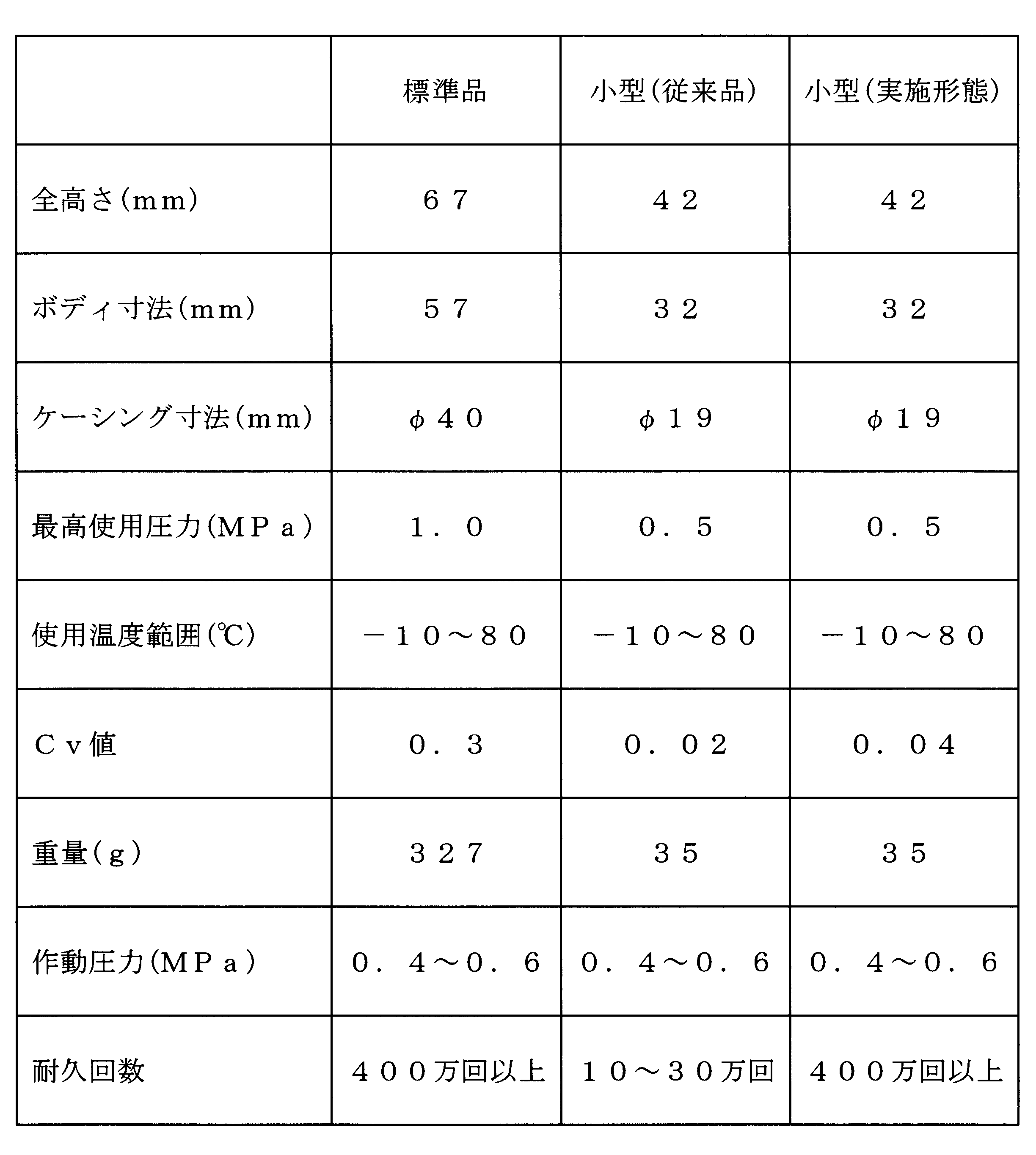
- Tables 1 and 2 show the comparison results of the first embodiment (small diaphragm valve) shown in FIGS. 1 and 2 and the conventional small diaphragm valve shown in FIG.
- Table 1 shows the differences between the first embodiment and the conventional small diaphragm valve shown in FIG. 6, and Table 2 shows a comparison with existing diaphragm valves of standard size (standard products). The specifications and performance are shown.
- the embodiment has extremely excellent durability, which is the same as that of the standard size, while being small, and more durable than the same small conventional product. It can be seen that not only the Cv value is increased.
- the Cv value is a capacity coefficient of the valve, and represents a flow rate when the fluid flows through the valve at a certain differential pressure.
- the shape (SR) of the diaphragm retainer (6) is SR42 and the retainer adapter (8 ) Is set to 9 °.
- the index of durability is set to “4 million times”, which is equivalent to that of the conventional product, the diaphragm holder (6) diaphragm is considered considering that the durability is 4 million times or more and there is a margin in durability.
- the curvature radius (SR) of the surface in contact with (5) is 30 mm or more, and the taper angle ( ⁇ ) of the lower surface of the holding adapter (8) is the bottom surface of the recess (2c) of the body (2) ( It is reasonable to set a condition for ensuring about 4 million times that the flat portion (14a) of 14) is 10 ° or less.
- Diaphragm (5) from diaphragm support (14c) of bottom surface (14) of recess (2c) of body (2) which is in pressure contact with diaphragm (5) when valve is opened The ratio of the distance C to the top is preferably 18: 1 to 30: 1.
- a preferable range of C when L is ⁇ 8 is 0.27 mm to 0.44 mm (about 0.25 mm to 0.45 mm).
- the ratio of the diameter of the diaphragm (5) and the distance from the recess (2c) bottom surface (14) of the body (2) in pressure contact with the diaphragm (5) to the top of the diaphragm (the height of the top of the diaphragm (5))
- the durability is remarkably reduced
- the flow rate is remarkably insufficient.
- the Cv value of the embodiment is twice that of the conventional one.
- the bottom surface (14) of the recess (2c) of the body (2) is flat.
- the point (14a) is provided with a counterbore (15) so as to include a portion opened to the bottom surface (14) of the recess (2c) of the fluid outflow passage (2b). That is, by providing the counterbore (15) and increasing the inlet area of the fluid outflow passage (2b), the Cv value is doubled compared to the conventional case.
- the Cv value decreases. That is, according to this embodiment, not only the decrease in the flow rate accompanying the shape change of the diaphragm (5) can be compensated, but also the flow rate can be greatly increased.
- the Cv value which is a contradictory performance
- the durability of the diaphragm are compatible at a high level.
- An annular groove (16) including a portion opened to the bottom surface (14) of the recess (2c) of 2b) may be provided.
- the depth of the annular groove (16) is larger than the depth of the counterbore (15).
- the portion holding the sheet (4) has the same shape as the conventional one.
- the sheet (4) can be caulked from both the outer diameter side and the inner diameter side of the sheet (4), and the sheet (4) is strongly fixed.
- the sheet (4) is caulked only from the inner diameter side of the sheet (4).
- the inlet area of the fluid outflow passage (2b) can be made larger than that of the annular groove (16), and the Cv value becomes larger.
- a counterbore (15) is provided as shown in FIG. 4, and the cross-sectional shape of the fluid outflow passage (2b) is a long hole (17). Good.
- the cross-sectional shape of the elongated hole (17) may be a semi-circular portion added to both ends of the rectangular portion, may be elliptical, or may be a crescent shape along the counterbore (15). Good.
- the long hole (17) can be combined with the annular groove (16) shown in FIG. That is, the cross-sectional shape of the fluid outflow passage (2b) that is circular in FIG. 3 may be the long hole (17) shown in FIG.
- the vertical movement means for moving up and down (6) is configured, the configuration of the vertical movement means is not limited to that shown in FIG.
- the diaphragm valve can be used as an on-off valve in the fluid control device shown in FIG. And since the said diaphragm valve is reduced in size and is excellent also in durability, the fluid control apparatus using this is used as a gas supply part in the semiconductor manufacturing apparatus in which size reduction is an issue. Suitable for
- Semiconductor manufacturing equipment includes CVD equipment, sputtering equipment, etching equipment, and the like.
- the CVD apparatus is an apparatus that includes an energy supply means, a vacuum chamber, a gas supply means (fluid control device), and an exhaust means, and forms a passive film (oxide film) on the wafer.
- Etching apparatus is an apparatus that is composed of an energy supply means, a processing chamber, a gas supply means (fluid control device), and an exhaust means, and that processes a material surface and the like by a corrosive action by a reactive gas.
- the sputtering apparatus is an apparatus for forming a film on the surface of a material, which includes a target, an energy supply means, a vacuum chamber, a gas supply means (fluid control device), and an exhaust means.
- the gas supply means (fluid control apparatus) is an indispensable configuration, and the semiconductor manufacturing apparatus can be downsized by reducing the size thereof. it can.
- the fluid control device is not limited to the one shown in FIG. 7, and the semiconductor manufacturing device is not limited at all.
- the durability of the diaphragm can be greatly improved, it is possible to contribute to the performance improvement of the diaphragm valve, the fluid control device including the diaphragm valve, and the semiconductor manufacturing apparatus.
Landscapes
- Engineering & Computer Science (AREA)
- General Engineering & Computer Science (AREA)
- Mechanical Engineering (AREA)
- Physics & Mathematics (AREA)
- Fluid Mechanics (AREA)
- Fluid-Driven Valves (AREA)
- Lift Valve (AREA)
- Drying Of Semiconductors (AREA)
- Plasma & Fusion (AREA)
Abstract
Description

Claims (8)
- 流体流入通路、流体流出通路および上向きに開口した凹所が設けられたボディと、ボディに形成された流体流入通路の周縁に配置されたシートと、シートに押圧・離間されることで流体流入通路の開閉を行う弾性変形可能な球殻状ダイヤフラムと、ダイヤフラムの外周縁部をボディの凹所底面との間で保持する押さえアダプタと、ダイヤフラムの中央部を押圧するダイヤフラム押さえと、ダイヤフラム押さえを上下移動させる上下移動手段とを備えており、押さえアダプタは、その下面全体が所定の傾斜角度とされたテーパ状とされており、ボディの凹所底面は、円形の平坦部と、平坦部の外周に連なり平坦部に対して凹まされている凹部とを有しているダイヤフラム弁において、
ダイヤフラム押さえのダイヤフラムに当接している面の曲率半径は、30mm以上とされており、押さえアダプタの下面のテーパ角度は、ボディの凹所底面の平坦部に対して10°以下とされていることを特徴とするダイヤフラム弁。 - ボディ凹所底面の平坦部に、流体流出通路の凹所の底面に開口している部分を含むように、溝が設けられており、ダイヤフラム押さえのダイヤフラムに当接している面の曲率半径は、50mm以下とされ、押さえアダプタの下面のテーパ角度は、ボディの凹所底面の平坦部に対して5°以上とされていることを特徴とする請求項1のダイヤフラム弁。
- 流体流入通路、流体流出通路および上向きに開口した凹所が設けられたボディと、ボディに形成された流体流入通路の周縁に配置されたシートと、シートに押圧・離間されることで流体流入通路の開閉を行う弾性変形可能な球殻状ダイヤフラムと、ダイヤフラムの外周縁部をボディの凹所底面との間で保持する押さえアダプタと、ダイヤフラムの中央部を押圧するダイヤフラム押さえと、ダイヤフラム押さえを上下移動させる上下移動手段とを備えており、押さえアダプタは、その下面全体が所定の傾斜角度とされたテーパ状とされており、ボディの凹所底面は、円形の平坦部と、平坦部の外周に連なり平坦部に対して凹まされている凹部とを有しているダイヤフラム弁において、
弁開時、ダイヤフラムの直径と、ダイヤフラムと圧接密着しているボディの凹所底面からダイヤフラム頂点までの距離との比が18:1~30:1であることを特徴とするダイヤフラム弁。 - 流体制御機器として、開閉弁を備えている流体制御装置であって、該開閉弁が請求項1から3までのいずれかに記載のダイヤフラム弁とされていることを特徴とする流体制御装置。
- 半導体製造装置で使用されることを特徴とする請求項4の流体制御装置。
- ガス供給部として請求項4の流体制御装置を備えたことを特徴とする半導体製造装置。
- 半導体製造装置は、CVD装置、スパッタリング装置またはエッチング装置であることを特徴とする請求項6の半導体製造装置。
- 請求項7の半導体製造装置を使用して半導体を製造することを特徴とする半導体製造方法。
Priority Applications (3)
| Application Number | Priority Date | Filing Date | Title |
|---|---|---|---|
| CN201580033235.3A CN106461097B (zh) | 2014-06-30 | 2015-06-17 | 隔膜阀、流体控制装置、半导体制造装置以及半导体制造方法 |
| KR1020167031847A KR101926952B1 (ko) | 2014-06-30 | 2015-06-17 | 다이어프램 밸브, 유체 제어 장치, 반도체 제조 장치 및 반도체 제조 방법 |
| US15/322,566 US10125876B2 (en) | 2014-06-30 | 2015-06-17 | Diaphragm valve, fluid control device, semiconductor manufacturing apparatus, and semiconductor manufacturing method |
Applications Claiming Priority (2)
| Application Number | Priority Date | Filing Date | Title |
|---|---|---|---|
| JP2014-134976 | 2014-06-30 | ||
| JP2014134976A JP6335685B2 (ja) | 2014-06-30 | 2014-06-30 | ダイヤフラム弁、流体制御装置、半導体製造装置および半導体製造方法 |
Publications (1)
| Publication Number | Publication Date |
|---|---|
| WO2016002514A1 true WO2016002514A1 (ja) | 2016-01-07 |
Family
ID=55019061
Family Applications (1)
| Application Number | Title | Priority Date | Filing Date |
|---|---|---|---|
| PCT/JP2015/067432 Ceased WO2016002514A1 (ja) | 2014-06-30 | 2015-06-17 | ダイヤフラム弁、流体制御装置、半導体製造装置および半導体製造方法 |
Country Status (6)
| Country | Link |
|---|---|
| US (1) | US10125876B2 (ja) |
| JP (1) | JP6335685B2 (ja) |
| KR (1) | KR101926952B1 (ja) |
| CN (1) | CN106461097B (ja) |
| TW (1) | TWI666402B (ja) |
| WO (1) | WO2016002514A1 (ja) |
Families Citing this family (10)
| Publication number | Priority date | Publication date | Assignee | Title |
|---|---|---|---|---|
| JP6929098B2 (ja) * | 2017-03-30 | 2021-09-01 | 株式会社キッツエスシーティー | メタルダイヤフラムバルブ |
| CN111836985A (zh) * | 2018-02-28 | 2020-10-27 | 株式会社富士金 | 阀装置以及流体控制装置 |
| CN111757998B (zh) * | 2018-03-19 | 2022-05-27 | 日立金属株式会社 | 隔膜阀以及使用该隔膜阀的质量流量控制装置 |
| WO2019193978A1 (ja) * | 2018-04-06 | 2019-10-10 | 株式会社フジキン | バルブ装置および流体制御装置、流体制御方法、半導体製造装置及び半導体製造方法 |
| CN113710939A (zh) * | 2019-04-26 | 2021-11-26 | 株式会社富士金 | 隔膜、阀、以及隔膜的制造方法 |
| TWI770615B (zh) * | 2020-09-22 | 2022-07-11 | 和正豐科技股份有限公司 | 氟樹脂膜片閥 |
| EP4530512A3 (en) | 2020-11-04 | 2025-05-14 | Swagelok Company | Valves with integrated orifice restrictions |
| KR20230093446A (ko) | 2020-11-06 | 2023-06-27 | 스웨이지락 캄파니 | 밸브 캐비티 캡 장치 |
| JP7636037B2 (ja) * | 2021-07-30 | 2025-02-26 | 株式会社フジキン | バルブ装置 |
| KR102582673B1 (ko) * | 2023-05-24 | 2023-09-25 | 주식회사 진검물산 | 과열 방지가 개선된 휴대용 가스버너용 압력조절기 |
Citations (3)
| Publication number | Priority date | Publication date | Assignee | Title |
|---|---|---|---|---|
| JP2006083959A (ja) * | 2004-09-16 | 2006-03-30 | Fujikin Inc | センサ付き継手部材 |
| JP2012026577A (ja) * | 2011-09-22 | 2012-02-09 | Fujikin Inc | ダイレクトタッチ型メタルダイヤフラム弁のバルブストローク調整方法 |
| JP2014009765A (ja) * | 2012-06-29 | 2014-01-20 | Fujikin Inc | ダイヤフラム弁 |
Family Cites Families (8)
| Publication number | Priority date | Publication date | Assignee | Title |
|---|---|---|---|---|
| US5449142A (en) * | 1994-12-12 | 1995-09-12 | Automatic Switch Company | Two-way cartridge valve for aggresive media |
| JP3701367B2 (ja) * | 1996-02-22 | 2005-09-28 | Smc株式会社 | ポペット弁 |
| US6758239B2 (en) * | 2001-11-09 | 2004-07-06 | Roger J. Gregoire | Metal diaphragm structure for pressure regulators |
| CN1894526A (zh) * | 2003-10-17 | 2007-01-10 | 松德沃技术公司 | 故障保险气动致动阀 |
| JP5138863B2 (ja) * | 2004-12-10 | 2013-02-06 | Ckd株式会社 | ダイアフラム弁 |
| JP5054904B2 (ja) * | 2005-08-30 | 2012-10-24 | 株式会社フジキン | ダイレクトタッチ型メタルダイヤフラム弁 |
| JP5565856B2 (ja) * | 2010-03-24 | 2014-08-06 | セイコーインスツル株式会社 | ダイアフラム、ダイアフラムバルブ、及びダイアフラムの製造方法 |
| CN203176426U (zh) * | 2013-03-28 | 2013-09-04 | 鞍钢股份有限公司 | 一种用于镀铝锌线炉区下溜槽火炬电磁阀橡胶阀芯 |
-
2014
- 2014-06-30 JP JP2014134976A patent/JP6335685B2/ja active Active
-
2015
- 2015-06-17 WO PCT/JP2015/067432 patent/WO2016002514A1/ja not_active Ceased
- 2015-06-17 US US15/322,566 patent/US10125876B2/en active Active
- 2015-06-17 KR KR1020167031847A patent/KR101926952B1/ko active Active
- 2015-06-17 CN CN201580033235.3A patent/CN106461097B/zh not_active Expired - Fee Related
- 2015-06-29 TW TW104120878A patent/TWI666402B/zh active
Patent Citations (3)
| Publication number | Priority date | Publication date | Assignee | Title |
|---|---|---|---|---|
| JP2006083959A (ja) * | 2004-09-16 | 2006-03-30 | Fujikin Inc | センサ付き継手部材 |
| JP2012026577A (ja) * | 2011-09-22 | 2012-02-09 | Fujikin Inc | ダイレクトタッチ型メタルダイヤフラム弁のバルブストローク調整方法 |
| JP2014009765A (ja) * | 2012-06-29 | 2014-01-20 | Fujikin Inc | ダイヤフラム弁 |
Also Published As
| Publication number | Publication date |
|---|---|
| KR101926952B1 (ko) | 2018-12-07 |
| TW201606219A (zh) | 2016-02-16 |
| CN106461097A (zh) | 2017-02-22 |
| US10125876B2 (en) | 2018-11-13 |
| KR20160141852A (ko) | 2016-12-09 |
| US20170152954A1 (en) | 2017-06-01 |
| TWI666402B (zh) | 2019-07-21 |
| CN106461097B (zh) | 2018-10-09 |
| JP6335685B2 (ja) | 2018-05-30 |
| JP2016011743A (ja) | 2016-01-21 |
Similar Documents
| Publication | Publication Date | Title |
|---|---|---|
| JP6336345B2 (ja) | ダイヤフラム弁、流体制御装置、半導体製造装置および半導体製造方法 | |
| JP6335685B2 (ja) | ダイヤフラム弁、流体制御装置、半導体製造装置および半導体製造方法 | |
| CN101233350B (zh) | 直接接触型金属隔膜阀 | |
| CN109899555B (zh) | 流体控制阀和流体控制阀的组装方法 | |
| US8881761B2 (en) | Steam supply system and check valve for use therein | |
| CN106164549B (zh) | 流体控制器 | |
| JP2014009765A (ja) | ダイヤフラム弁 | |
| TWI690670B (zh) | 隔膜閥 | |
| JP2018132194A (ja) | ダイヤフラム弁、流体制御装置、半導体制御装置および半導体制御方法 | |
| JP5779559B2 (ja) | ダイヤフラム弁 | |
| US11002372B2 (en) | Diaphragm valve | |
| CN112585386A (zh) | 与流体阀一起使用的阀盘 | |
| JP7262559B2 (ja) | バルブ用アクチュエータとこれを備えたダイヤフラムバルブ | |
| CN111577907B (zh) | 阀装置 | |
| JP2791546B2 (ja) | 金属製のダイヤフラムを有した制御弁 | |
| JP2609400B2 (ja) | ダイヤフラム弁のダイヤフラム | |
| JPH06294471A (ja) | ダイヤフラム型流体制御器 |
Legal Events
| Date | Code | Title | Description |
|---|---|---|---|
| 121 | Ep: the epo has been informed by wipo that ep was designated in this application |
Ref document number: 15815944 Country of ref document: EP Kind code of ref document: A1 |
|
| ENP | Entry into the national phase |
Ref document number: 20167031847 Country of ref document: KR Kind code of ref document: A |
|
| WWE | Wipo information: entry into national phase |
Ref document number: 15322566 Country of ref document: US |
|
| NENP | Non-entry into the national phase |
Ref country code: DE |
|
| 122 | Ep: pct application non-entry in european phase |
Ref document number: 15815944 Country of ref document: EP Kind code of ref document: A1 |