WO2016002067A1 - 台車装置 - Google Patents
台車装置 Download PDFInfo
- Publication number
- WO2016002067A1 WO2016002067A1 PCT/JP2014/067905 JP2014067905W WO2016002067A1 WO 2016002067 A1 WO2016002067 A1 WO 2016002067A1 JP 2014067905 W JP2014067905 W JP 2014067905W WO 2016002067 A1 WO2016002067 A1 WO 2016002067A1
- Authority
- WO
- WIPO (PCT)
- Prior art keywords
- handle
- cart
- wheels
- pair
- width direction
- Prior art date
- Legal status (The legal status is an assumption and is not a legal conclusion. Google has not performed a legal analysis and makes no representation as to the accuracy of the status listed.)
- Ceased
Links
Images


Classifications
-
- B—PERFORMING OPERATIONS; TRANSPORTING
- B62—LAND VEHICLES FOR TRAVELLING OTHERWISE THAN ON RAILS
- B62B—HAND-PROPELLED VEHICLES, e.g. HAND CARTS OR PERAMBULATORS; SLEDGES
- B62B3/00—Hand carts having more than one axis carrying transport wheels; Steering devices therefor; Equipment therefor
-
- B—PERFORMING OPERATIONS; TRANSPORTING
- B62—LAND VEHICLES FOR TRAVELLING OTHERWISE THAN ON RAILS
- B62B—HAND-PROPELLED VEHICLES, e.g. HAND CARTS OR PERAMBULATORS; SLEDGES
- B62B5/00—Accessories or details specially adapted for hand carts
- B62B5/04—Braking mechanisms; Locking devices against movement
Definitions
- the present invention relates to a cart apparatus that has a pair of wheels and is used for transportation and the like.
- a cart device (electrically assisted cart, mobile cart) that transports an object to be conveyed such as food provided in a facility such as a hotel or a hospital
- an operation is performed using a handle provided in front of the cart device.
- a cart device there is known a configuration in which a driving force of an electric motor is distributed to a pair of wheels by combining a single electric motor and a differential gear (see, for example, Patent Document 1).
- This bogie device achieves turning of the bogie device by swinging a handle to brake one wheel. Further, since the vehicle can be driven by a single electric motor, for example, it can be manufactured at a lower cost as compared with a two-motor bogie device having two electric motors and wheels connected to each electric motor. Is possible.
- the object of the present invention is to provide a cart device that enables the cart to turn with a more intuitive operation.
- a carriage device includes a carriage body having a pair of wheels, a pair of braking devices provided corresponding to the pair of wheels and capable of braking the wheels, and
- the vehicle body can be operated in the longitudinal direction of the carriage body and in the width direction of the carriage body.
- one of the wheels is braked via the braking device, and It has an operation part which brakes a wheel opposite to the one wheel via the braking device by operating in a second direction opposite to the one direction.
- the cart body can be turned left and right, so that the operator can operate the cart device more intuitively.
- a drive device having an output shaft for rotational driving, a differential device for rotating the wheels by distributing an output corresponding to the rotational speed of the output shaft to the pair of wheels, and front and rear of the operation unit It is good also as a structure which has a control apparatus which sets the rotation speed of the said output shaft based on the target speed determined by the operation amount of a direction.
- the cart body is driven by the driving force output from the driving device, so that the burden on the operator can be reduced. Further, since the target speed is determined by the operation amount of the operation unit, the operator can adjust the speed of the carriage device more intuitively.
- the operation section is provided across the width direction of the cart body, and is operable in the width direction of the cart body with respect to the handle body. It is good also as a structure which has the brake handle attached.
- the handle main body is pivotally attached to the front surface of the cart, has a tubular shape curved in an arc shape, and the brake handle is slidable in the extending direction of the handle main body.
- the force applied to the gripping portion becomes a large force at the transmission member by the lever principle using the spherical joint as a fulcrum, so that the braking device can be operated with a smaller force.
- the operation of the operation unit to the left and right allows the operation of the left and right turn of the bogie body, the operator can more intuitively operate the bogie device.
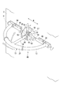
- FIG. 1 is a perspective view schematically showing a cart apparatus 1 according to an embodiment of the present invention.
- the carriage device 1 operates the carriage device 1 and a carriage main body 2 having a pair of wheels 3 (only one side is shown in FIG. 1) that are separated in a width direction W orthogonal to the traveling direction T.
- a handle 4 which is an operation unit for the purpose.
- the cart apparatus 1 of the present embodiment is a so-called power assist cart that assists an operator using the driving force of an electric motor (driving apparatus).
- the X direction shown in FIG. 1 indicates the longitudinal direction X of the carriage device 1.
- the W direction shown in FIG. 1 indicates the width direction W of the carriage device 1.
- the arrow T shown in FIG. 1 points to the front of the traveling direction T of the carriage device 1.
- the cart body 2 for example, a box-shaped one having the inside as a storage portion can be adopted.
- a door 8 can be attached to the cart body 2.
- the pair of wheels 3 are spaced apart from each other in the width direction W of the carriage body 2 and can rotate at independent rotation speeds.
- the pair of wheels 3 can turn left and right by giving a speed difference between the left and right.
- the pair of wheels 3 is disposed at the approximate center in the longitudinal direction X of the carriage body 2.
- Casters 9 are attached in the vicinity of both ends in the longitudinal direction X of the main body 2 and in the vicinity of both ends in the width direction W.
- a drive unit accommodating portion 10 for arranging an electric motor 16 (see FIG. 2), which will be described later, and the like is provided at the lower portion of the cart body 2.
- the drive unit accommodating unit 10 accommodates a control device 5 (see FIG. 2) for controlling the handle operation of the operator and the rotation speed of the electric motor 16.
- the handle 4 includes a handle body 12 extending in the width direction W of the carriage body 2 and a slider portion 13 (braking handle) that is slidably attached to the handle body 12. The operator can simultaneously operate the handle body 12 and the slider unit 13. That is, the slider portion 13 can be slid while performing an operation of tilting the handle body 12 while holding the slider portion 13.
- the operator adjusts the speed of the carriage device 1 with the handle body 12 that can be operated in the front-rear direction, and performs the turning operation of the carriage device 1 with the slider portion 13 that can be operated in the width direction W.
- the slider portion 13 of the handle 4 has a function of causing the cart body 2 to bend and travel by selectively braking one of the pair of wheels 3. That is, while the carriage main body 2 is traveling, the carriage main body 2 can be bent to the right by sliding the slider portion 13 to the right in the width direction W and braking the right wheel 3.
- the cart device 1 of the present embodiment turns the cart body 2 left and right by creating a speed difference between the left and right wheels 3 using a braking device 20 described later.
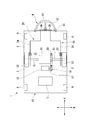
- FIG. 2 is a plan view illustrating a schematic configuration of the cart apparatus 1 of the present embodiment.
- the carriage device 1 distributes the output (driving force) according to the rotation speed of the single electric motor 16 and the output shaft 17 of the electric motor 16 to the pair of wheels 3 to distribute the wheels 3.
- a differential device 19 that rotates and a pair of braking devices 20 that brake the pair of wheels 3 are provided.
- the pair of wheels 3 are connected to the differential device 19 via the axle 15.
- the differential device 19 is disposed substantially at the center of the carriage body 2 (the center in the longitudinal direction X and the center in the width direction W).
- As the electric motor 16 for example, a geared motor integrated with a reduction gear can be adopted.
- the electric motor 16 has an output shaft 17 that is rotationally driven.
- a drive gear 18 is attached to the output shaft 17.
- the drive gear 18 is disposed so as to mesh with the ring gear 30 of the differential device 19.
- the braking device 20 is provided corresponding to the pair of wheels 3 and is a brake capable of braking each of the pair of wheels 3.
- the braking device 20 includes a pair of brake rotors 22 that rotate together with the wheels 3, a pair of brake calipers 23 that are disposed at positions sandwiching the brake rotors 22, a brake caliper 23, and a master that is attached to the front surface of the cart body 2.
- This is a hydraulic brake having a hose 24 connected to the cylinder 36.
- the master cylinder 36 is configured to be operated in conjunction with the movement of the slider portion 13.
- the braking device 20 brakes the left wheel 3 and moves the slider 13 from the center of the handle 4 in the width direction W.
- the right wheel 3 is braked.
- the force applied to the slider portion 13 is converted into hydraulic pressure via the master cylinder 36 and the brake caliper 23 is operated via the hose 24.
- the braking device 20 is not limited to a hydraulic brake as long as the wheel 3 can be braked according to the movement of the slider portion 13, and other types of braking devices can be employed.
- a mechanical brake that transmits the movement of the slider portion 13 to the brake caliper 23 using a wire or the like may be employed.
- an electromagnetic brake that operates the brake caliper 23 using the action of an electromagnet can be employed.
- the handle 4 is attached to the front side in the traveling direction T of the carriage body 2 so as to be rotatable about the rotation center axis A.
- the handle 4 has a handle angle detection device 14 for detecting a rotation angle ⁇ (operation amount) around the rotation center axis A of the handle 4.
- a potentiometer can be adopted as the handle angle detection device 14.
- the handle angle detection device 14 and the control device 5 are electrically connected, and the rotation angle ⁇ of the handle 4 detected by the handle angle detection device 14 is input to the control device 5.
- a voltage (analog value) output from the potentiometer is converted into a rotation angle ⁇ (digital value) via an analog-digital conversion circuit (A / D conversion circuit) and input to the control device 5. .
- any other device can be adopted as long as it is an angular position sensor.
- a rotary encoder can be used.
- a pulse counter board is used instead of the A / D conversion circuit.
- the handle body 12 is, for example, a biasing member (not shown) such as a torsion coil spring so that the central portion (attachment position of a gripping portion 37 described later) is always directed upward in the vertical direction (two points in FIG. 3). It is energized (to the position indicated by the chain line).
- the urging member of the handle body 12 functions as an operation resistance unit that increases in resistance in proportion to the operation amount and increases the operation force.
- the handle main body 12 is in close contact with the carriage main body 2 without any operation by the operator, and the operator operates the counter member against the urging force of the urging member to tilt the central portion forward in the traveling direction T. Can do.
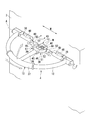
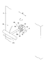
- FIG. 4 shows a perspective view of the handle 4 of the cart apparatus 1 of the present embodiment.
- the rotation angle of the handle body 12 shown in FIG. 4 is about 90 °.
- the handle body 12 is formed of a tubular member having a circular cross section, and has a tubular shape curved in an arc shape so as to draw a semicircle.
- the handle body 12 is attached such that the center of an arc (semicircle) drawn by the center axis of the handle body 12 is positioned on the rotation center axis A.
- Both ends of the handle main body 12 are attached to the front surface of the cart main body 2 so as to be rotatable about the rotation center axis A.
- the handle body 12 is attached so that the heights of the attachment positions at both ends of the handle body 12 are the same.
- the center in the width direction W on the rotation center axis A is defined as a handle center position M.
- the center position M substantially coincides with the center of the arc drawn by the center axis of the handle body 12.
- the slider portion 13 includes a gripping portion 37 slidably attached in the extending direction of the handle body 12, a center stay portion 38 formed integrally with the gripping portion 37, and a cam portion 39 attached to the center stay portion 38. And have.
- the slider portion 13 functions as an interface of the braking device 20 that can operate the braking device 20 by sliding the slider portion 13 along the handle body 12.
- the gripping part 37 is a cylindrical member bent in an arc shape, and is attached to the vicinity of the center part of the handle body 12 so as to cover the peripheral surface of the handle body 12.
- the grip portion 37 is urged in a direction toward the central portion of the handle main body 12 by a predetermined urging member.
- the grip portion 37 is positioned at the center portion of the handle main body 12 without being operated by the operator, and is operated by the operator against the urging force of the urging member. It is comprised so that it can be slid to either.
- the center stay part 38 is a shaft-shaped member extending between the grip part 37 and the handle center position M, and a first end of the center stay part 38 is connected to the grip part 37.
- the second end portion of the center stay portion 38 opposite to the first end portion is rotatable about the rotation center axis A and swingable in the width direction W around the handle center position M. It is attached to the cart body 2.
- the second end of the center stay portion 38 is connected to the vicinity of the handle center position M via a spherical joint 40. That is, the center stay portion 38 is rotatable around the rotation center axis A as the handle body 12 rotates. Further, the center stay portion 38 can swing around the handle center position M as the slider portion 13 slides regardless of the rotation position (rotation angle ⁇ ) of the handle body 12.
- the spherical joint 40 includes a bracket 41, a shaft portion 42 fixed to the bracket 41, and a joint shaft portion 43 that is rotatably attached to the shaft portion 42.
- the shaft portion 42 extends in a direction along the rotation center axis A, and has a spherical portion 44 at the center portion.
- the joint shaft portion 43 includes an outer ring portion 45 attached so as to be in surface contact with the spherical surface portion 44 of the shaft portion 42, and a stay portion 46 that is formed integrally with the outer ring portion 45 and extends in one direction. is doing.
- the stay portion 46 is connected to the center stay portion 38 so as to be in a straight line.
- the master cylinder 36 has a cylindrical cylinder portion 48, a rod portion 49 that can slide in the cylinder portion 48, and a pad portion 50 that is attached to the tip of the rod portion 49.
- the pad portion 50 has a hemispherical shape on the tip side.
- the master cylinder 36 is arranged so that the axial directions of the cylinder portion 48 and the rod portion 49 are along the rotation center axis A, and the tips (pad portions 50) of the rod portions 49 of the pair of master cylinders 36 are opposed to each other. ing.
- the cam portion 39 is provided integrally with the center stay portion 38 in the vicinity of the second end portion of the center stay portion 38, and transmits a movement of the center stay portion 38 (slider portion 13) to the master cylinder 36 (cam mechanism). ). Specifically, the cam portion 39 transmits the movement of the center stay portion 38 that swings left and right as the slider portion 13 moves in the width direction W to the pad portion 50 of the master cylinder 36.
- the cam portion 39 includes a protruding portion 51 that protrudes from the center stay portion 38 toward the pad portion 50 of the master cylinder 36, and a slope portion 52 that is formed at the tip of the protruding portion 51 and contacts the pad portion 50. .
- the slope portion 52 of the cam portion 39 is in contact with the pad portion 50 of the master cylinder 36 when the slider portion 13 is located at the center of the handle body 12, and when the slider portion 13 is slid and moved, The rod part 49 is pushed in through 50.
- the brake device 20 can be operated by operating the slider portion 13 regardless of the position of the handle body 12 in the front-rear direction (rotation angle ⁇ ). That is, as shown in FIG. 5, the operation of the slider portion 13 in the width direction W is operated in the direction in which the rod portion 49 of the master cylinder 36 contracts, whereby the braking device 20 connected to the master cylinder 36 (see FIG. 2). ) Is activated.
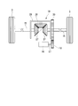
- the differential device 19 is provided integrally with the pair of side gears 27, the pinion gear 28 that meshes with the pair of side gears 27, the casing 29 that supports the pinion gear 28, and the casing 29.
- This is a differential gear (differential gear) having a ring gear 30 that meshes with a drive gear 18 that is rotated by a drive force of 16.
- the pair of axles 15 is attached to the side gear 27. That is, the wheel 3 is configured to rotate via the axle 15 as the side gear 27 rotates.
- control device 5 controls the electric motor 16 so that the carriage device 1 moves forward at a speed proportional to the rotation angle ⁇ .
- control method of the electric motor 16 by the control apparatus 5 is not restricted to the method mentioned above. For example, at a low speed, control may be performed so as to start more smoothly by decreasing the rate of change of the speed with respect to the rotation angle ⁇ of the handle 4. That is, the mapping of the speed to the handle angle ⁇ can be freely set.
- the operator When the operator turns the carriage device 1, the operator operates the slider portion 13 while operating the handle 4 forward in the traveling direction T.
- the slider portion 13 of the handle 4 When the operator turns the cart device 1 in the right direction, the slider portion 13 of the handle 4 is slid in the right direction (first direction).
- the right master cylinder 36 is operated in the traveling direction T via the cam portion 39, and the right wheel 3 (one wheel) is braked.
- the speed of the left wheel 3 is increased and the carriage device 1 turns rightward.
- the four slider portions 13 of the handle 4 are slid in the left direction (second direction opposite to the first direction). Thereby, the left wheel 3 (the wheel opposite to the one wheel) is braked, and the carriage device 1 turns leftward.
- the cart body 2 can be operated to turn left and right, so that the operator can operate the cart device 1 more intuitively.
- the driving force of one electric motor 16 is distributed to the left and right wheels 3 using the differential device 19 and the cart body 2 is bent by braking one of the left and right wheels 3, It is possible to provide a cart apparatus 1 that can perform stable forward and backward movement and left and right turn at lower cost.
- the cart body 2 is driven by the driving force of the electric motor 16 the burden on the operator can be reduced. Further, since the target speed is determined by the operation amount of the handle 4, the operator can adjust the speed of the carriage device 1 more intuitively.
- the braking device 20 is operated with a smaller force. be able to. Further, by using the cam portion 39, the movement of the slider portion 13 can be transmitted to the master cylinder 36 with fewer components.
- the cart apparatus 1 of 2nd embodiment of this invention is demonstrated based on drawing.
- differences from the first embodiment described above will be mainly described, and description of similar parts will be omitted.
- the cart apparatus 1 of this embodiment transmits the movement of the slider portion 13 to the master cylinder 36 using a box-shaped member 54 that is slidably attached to the front surface of the cart body 2 in the width direction W.
- the box-shaped member 54 has a pair of facing surfaces 55 and a connection surface 56 that connects the pair of facing surfaces 55 to each other.
- the pair of opposed surfaces 55 are arranged so as to be orthogonal to the rotation center axis A (the axial direction of the rod portion 49 of the master cylinder 36).
- the box-shaped member 54 is attached to the front surface of the cart body 2 such that the connection surface 56 is parallel to the front surface of the cart body 2 and is slidable in the width direction W.
- the box-shaped member 54 is arranged so that the pair of opposed surfaces 55 of the box-shaped member 54 abut against the pad portion 50 of the master cylinder 36 via a linear motion guide member 57 such as a linear motion guide. It is attached to the cart body 2.
- the center stay portion 38 is formed with a pair of box drive members 58 that project in the width direction.
- the box drive member 58 is formed such that the end in the width direction W abuts against the inner surfaces of the pair of opposed surfaces 55 of the box-shaped member 54. That is, the distance dimension between the ends of the pair of box drive members 58 is formed to be substantially the same as the distance dimension between the pair of opposed surfaces 55 or slightly shorter than the distance dimension between the pair of opposed surfaces 55. .
- the pair of opposing surfaces 55 of the box-shaped member 54 are formed so that the box drive member 58 can come into contact with the handle body 12 at any position. That is, the pair of opposing surfaces 55 of the box-shaped member 54 has a shape corresponding to the locus of the box drive member 58 when the handle body 12 is rotated.
- the box-shaped member 54 moves left and right via the box driving member 58 by operating the slider portion 13.
- the rod portion 49 of the master cylinder 36 is driven by the movement of the box-shaped member 54.
- the pair of opposing surfaces 55 have a shape corresponding to the movement of the box driving member 58, the slider portion 13 is slid regardless of the position of the handle main body 12, thereby the box-shaped member. 54 can be driven.
- the pair of opposed surfaces 55 are arranged so as to be orthogonal to the axial direction of the rod portion 49 of the master cylinder 36, the movement of the slider portion 13 can be reliably transmitted to the master cylinder 36.
- the cart apparatus 1 of 3rd embodiment of this invention is demonstrated based on drawing.
- the center stay portion 38 ⁇ / b> C of the cart device 1 of the present embodiment is supported by the gimbal mechanism portion 60 so as to be rotatable about the rotation center axis A and swingable in the width direction W.
- the gimbal mechanism 60 is fixed to the front surface of the cart body 2, and includes a first gimbal bracket 61 that supports the first gimbal shaft 62 and a second gimbal shaft 63 that is rotatably supported by the first gimbal shaft 62. And a second gimbal bracket 64 that is rotatably attached to both ends of the second gimbal shaft 63.
- the center stay portion 38 ⁇ / b> C is connected to the second gimbal bracket 64.
- the first gimbal bracket 61 is fixed to the center of the rotation center axis A in the width direction W, and rotatably supports a first gimbal shaft 62 extending in parallel with the rotation center axis A. That is, the first gimbal shaft 62 is a rotation shaft that is parallel to the front surface of the carriage body 2 and extends in the horizontal direction.
- the second gimbal shaft 63 is an axis that is orthogonal to the first gimbal shaft 62 and is rotatable about the first gimbal shaft 62.
- the second gimbal shaft 63 is a cylindrical member having a predetermined length, and a through hole through which the first gimbal shaft 62 passes is formed in the center in the longitudinal direction.
- the through hole is a circular hole and is formed so that the central axis of the through hole is orthogonal to the central axis of the second gimbal shaft 63.
- the second gimbal bracket 64 is a U-shaped member having a pair of opposing shaft connection surfaces 65 and a stay connection surface 66 that connects the pair of shaft connection surfaces 65.
- the opposing surfaces of the pair of shaft connection surfaces 65 are connected to the second gimbal shaft 63.
- the stay connection surface 66 of the second gimbal bracket 64 is formed so that the main surface of the stay connection surface 66 is parallel to the central axis of the second gimbal shaft 63.
- a grip portion 37C is connected to an end portion of the center stay portion 38C.
- the gripping portion 37C of this embodiment is not a slide type. That is, the handle 4 according to this embodiment does not have a handle body that functions as a rail of the grip portion.
- the center stay portion 38C is urged by a predetermined urging member such as a torsion coil spring so that the end portion to which the grip portion 37C is connected is always directed upward in the vertical direction.
- the center stay portion 38C is urged in a direction toward the central portion in the width direction W by a predetermined urging member. That is, the center stay portion 38C is biased so that the grip portion 37C is positioned above and the center axis of the center stay portion 38C is along the vertical direction in a state where no force is applied by the operator. .
- the gimbal mechanism 60 has an angle detection device that detects the rotation angle in the width direction W and the rotation angle in the front-rear direction of the center stay portion 38C.
- the braking device of the present embodiment is configured by an electromagnetic brake.
- the control device of the present embodiment is configured to operate the electromagnetic brake according to the rotation angle in the width direction W of the center stay portion 38C. That is, when the center stay portion 38 is tilted to the right, the right wheel 3 is braked, and when the center stay portion 38 is tilted to the left, the left wheel 3 is braked. Yes.
- the member that supports the center stay portion on the front surface of the cart body 2 is not limited to the spherical joint, and a gimbal mechanism can also be used. Further, a method of electrically detecting the movement of the handle in the width direction W as well as a mechanical transmission mechanism can be employed. That is, an electromagnetic brake can be used as an alternative to the hydraulic brake that mechanically transmits the movement of the handle to the braking device. It is also possible to adopt a configuration in which the handle main body that guides the grip portion is eliminated.
- the electromagnetic brake for example, it is possible to perform control such as slightly braking the wheel on the side opposite to the turning direction. That is, it is possible to freely map the angle of the handle 4C and the braking force to the wheel 3.
- the movement of the handle 4C in the width direction W may be mechanically transmitted like a cam mechanism as described in the first embodiment. That is, a structure such as the cam portion 39 (see FIG. 4) of the first embodiment is added to the second gimbal bracket 64 or the center stay portion 38C of the gimbal mechanism portion 60, and the wheel is braked using a hydraulic brake. It can also be.
- the cart apparatus 1 of 3rd embodiment of this invention is demonstrated based on drawing.
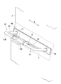
- the handle 4 ⁇ / b> D of the present embodiment is attached to a rectangular plate-like base portion 69 that is attached to the front surface of the cart body 2 via a rectangular plate-like force sensor 68, and the base portion 69.
- a handle body 12D, and a slider portion 13D slidably attached to the handle body 12D.
- the force sensor 68 is a plate-like sensor that senses an operation force in the front-rear direction applied to the handle main body 12 ⁇ / b> D via the base portion 69.
- the force sensor 68 is connected to the control device.
- the handle main body 12 ⁇ / b> D is a bar-like handle having a horizontal bar portion 70 extending in the width direction W and a support portion 71 that connects both ends of the horizontal bar portion 70 and the base portion 69.
- a master cylinder 36 having the same configuration as that of the first embodiment is attached to the horizontal bar portion 70.
- the slider portion 13 is slidably attached to the handle body 12D, and flange portions 72 are formed at both ends thereof.
- the slider portion 13D is configured to drive the master cylinder 36 by sliding the slider portion 13D.
- the control device controls the speed of the carriage device 1 based on the operation force in the front-rear direction applied to the handle body 12D.
- the handle 4D can be made compact by using the plate-like force sensor 68 and integrating the master cylinder 36 with the handle body 12D.
- the present invention is not limited by the embodiments, and is limited only by the scope of the claims.
- the electric motor 16 is used as the drive device.
- the handle 4 of the present embodiment is also applied to a cart that manually moves the cart body 2 without providing a drive device that drives the wheels 3. Can be applied. That is, the movement of the cart body 2 in the front-rear direction may be performed manually.
- the cart apparatus 1 of the said embodiment is a structure which provides the handle 4 only in the front side of the front-back direction, you may provide the handle 4 also in the back side in addition to the front side. That is, it is good also as the trolley
- a hydraulic brake is used as the braking device 20 in the cart apparatus 1 having such a configuration
- a system hose 24 is required. It is preferable to use a drive valve such as an electromagnetic valve (solenoid valve) for switching between the two braking systems 20.
Landscapes
- Engineering & Computer Science (AREA)
- Chemical & Material Sciences (AREA)
- Combustion & Propulsion (AREA)
- Transportation (AREA)
- Mechanical Engineering (AREA)
- Handcart (AREA)
Abstract
一対の車輪(3)を有する台車本体(2)と、一対の車輪(3)に対応して設けられて、車輪(3)をそれぞれ制動可能な一対の制動装置(20)と、台車本体(2)の前後方向及び台車本体(2)の幅方向に操作可能であり、幅方向の第一の方向に操作することで制動装置(20)を介して一方の車輪(3)を制動し、幅方向の第一の方向とは反対の第二の方向に操作することで制動装置(20)を介して一方の車輪とは反対の車輪を制動する操作部(4)、を有する台車装置(1)。
Description
本発明は、一対の車輪を有し、搬送用途などに使用される台車装置に関する。
例えば、ホテルや病院などの施設において提供される食品などの被搬送物を搬送する台車装置(電動アシスト台車、移動式カート)としては、台車装置の前方に設けられたハンドルを用いて操作する形態のものが一般的である。
このような台車装置としては、一つの電動モーターと、差動歯車を組み合わせることによって、電動モーターの駆動力を一対の車輪に分配する形態のものが知られている(例えば特許文献1参照)。
このような台車装置としては、一つの電動モーターと、差動歯車を組み合わせることによって、電動モーターの駆動力を一対の車輪に分配する形態のものが知られている(例えば特許文献1参照)。
この台車装置は、ハンドルを揺動させて一方の車輪を制動させることによって台車装置の旋回を実現している。また、単一の電動モーターによって走行が可能であるため、例えば、二つの電動モーターと各々の電動モーターに接続された車輪を有する2モーター式の台車装置と比較して、より低コストでの製造が可能となる。
しかしながら、特許文献1に記載されているような台車装置の場合、旋回時におけるハンドル操作がハンドルを捻るような操作であるため、旋回動作が難しいという課題があった。
本発明は、より直感的な操作で、台車の旋回を可能にする台車装置を提供することを目的とする。
本発明の第一の態様によれば、台車装置は、一対の車輪を有する台車本体と、前記一対の車輪に対応して設けられて、前記車輪をそれぞれ制動可能な一対の制動装置と、前記台車本体の前後方向及び前記台車本体の幅方向に操作可能であり、前記幅方向の第一の方向に操作することで前記制動装置を介して一方の前記車輪を制動し、前記幅方向の第一の方向とは反対の第二の方向に操作することで前記制動装置を介して前記一方の車輪とは反対の車輪を制動する操作部、を有することを特徴とする。
このような構成によれば、操作部を左右に操作することによって、台車本体の左右旋回の操作が可能となるため、操作者はより直感的に台車装置を操作することができる。
上記台車装置において、回転駆動する出力軸を有する駆動装置と、前記出力軸の回転数に応じた出力を前記一対の車輪に分配して前記車輪を回転させる差動装置と、前記操作部の前後方向の操作量によって決定される目標速度に基づいて前記出力軸の回転数を設定する制御装置と、を有する構成としてもよい。
このような構成によれば、駆動装置が出力する駆動力によって台車本体が駆動されるため、操作者の負担を軽減することができる。また、目標速度が操作部の操作量によって決定されるため、操作者はより直感的に台車装置の速度を調整することが可能になる。
上記台車装置において、前記操作部は、前記台車本体の幅方向に亘って設けられ、前記台車本体の前後方向に操作可能なハンドル本体と、前記ハンドル本体に対して前記台車本体の幅方向に操作可能に取り付けられている制動ハンドルと、を有する構成としてもよい。
上記台車装置において、前記ハンドル本体は、両端が前記台車の前面に回動自在に取り付けられ、円弧状に湾曲した管形状をなし、前記制動ハンドルは、前記ハンドル本体の延在方向にスライド自在に取り付けられた把持部と、前記把持部と一体に形成され前記台車本体の前面に球面ジョイントを介して接続されたセンターステー部と、センターステー部に取り付けられて前記把持部の幅方向の動きを前記制動装置に伝達する伝達部材と、を有する構成としてもよい。
このような構成によれば、把持部に加えられた力が球面ジョイントを支点とした、てこの原理によって、伝達部材で大きな力となるため、より小さな力で制動装置を作動させることができる。
本発明によれば、操作部を左右に操作することによって、台車本体の左右旋回の操作が可能となるため、操作者はより直感的に台車装置を操作することができる。
以下、本発明の実施形態の台車装置1について図面を参照して詳細に説明する。なお、以下の説明で用いる図面は、本発明の実施形態の構成を説明するためのものであり、図示される各部の大きさや厚さや寸法等は、実際の台車装置1の寸法関係とは異なる場合がある。
図1は、本発明の実施形態の台車装置1を模式的に示す斜視図である。図1に示すように、台車装置1は、進行方向Tに直交する幅方向Wに離間する一対の車輪3(図1には片側のみ示す)を有する台車本体2と、台車装置1を操作するための操作部であるハンドル4と、を有している。
図1は、本発明の実施形態の台車装置1を模式的に示す斜視図である。図1に示すように、台車装置1は、進行方向Tに直交する幅方向Wに離間する一対の車輪3(図1には片側のみ示す)を有する台車本体2と、台車装置1を操作するための操作部であるハンドル4と、を有している。
本実施形態の台車装置1は、電動モーター(駆動装置)の駆動力を用いて操作者をアシストする、所謂パワーアシストカートである。
なお、図1に示すX方向は台車装置1の長手方向Xを示している。図1に示すW方向は台車装置1の幅方向Wを示している。また、図1に示す矢印Tは台車装置1の進行方向Tの前方を指している。
なお、図1に示すX方向は台車装置1の長手方向Xを示している。図1に示すW方向は台車装置1の幅方向Wを示している。また、図1に示す矢印Tは台車装置1の進行方向Tの前方を指している。
台車本体2は、例えば、内部を収納部とした箱型のものを採用することができる。台車本体2には扉8を取り付けることができる。
一対の車輪3は、台車本体2の幅方向Wに離間して配置されて、互いに独立した回転数で回転可能である。一対の車輪3は、左右で速度差を付けることで、左右の旋回が可能である。一対の車輪3は、台車本体2の長手方向Xの略中央に配置されている。台車本体2の長手方向Xの両端部近傍であって、幅方向Wの両端部近傍には、キャスター9が取り付けられている。
一対の車輪3は、台車本体2の幅方向Wに離間して配置されて、互いに独立した回転数で回転可能である。一対の車輪3は、左右で速度差を付けることで、左右の旋回が可能である。一対の車輪3は、台車本体2の長手方向Xの略中央に配置されている。台車本体2の長手方向Xの両端部近傍であって、幅方向Wの両端部近傍には、キャスター9が取り付けられている。
また、台車本体2の下部には、後述する電動モーター16(図2参照)などを配置するための駆動部収容部10が設けられている。駆動部収容部10には、操作者のハンドル操作、及び電動モーター16の回転数を制御するための制御装置5(図2参照)が収容されている。
ハンドル4は、台車本体2の幅方向Wに亘って延びるハンドル本体12と、ハンドル本体12に対してスライド可能に取り付けられているスライダー部13(制動ハンドル)と、を有している。操作者は、ハンドル本体12の操作と、スライダー部13の操作を同時に行うことができる。即ち、スライダー部13を把持してハンドル本体12を傾ける動作を行いながら、スライダー部13をスライドさせることができる。
ハンドル4は、台車本体2の幅方向Wに亘って延びるハンドル本体12と、ハンドル本体12に対してスライド可能に取り付けられているスライダー部13(制動ハンドル)と、を有している。操作者は、ハンドル本体12の操作と、スライダー部13の操作を同時に行うことができる。即ち、スライダー部13を把持してハンドル本体12を傾ける動作を行いながら、スライダー部13をスライドさせることができる。
操作者は、前後方向に操作可能なハンドル本体12によって台車装置1の速度を調整し、幅方向Wに操作可能なスライダー部13によって台車装置1の旋回動作を行う。
本実施形態の台車装置1は、ハンドル4のスライダー部13は、一対の車輪3のいずれかを選択的に制動させることで、台車本体2を曲進走行させる機能を有している。即ち、台車本体2の走行中に、スライダー部13を幅方向Wの例えば右方向にスライドさせて右側の車輪3を制動することにより、台車本体2を右方向に曲げることができる。換言すれば、本実施形態の台車装置1は、後述する制動装置20を用いて左右の車輪3に速度差を作ることによって、台車本体2の左右旋回を行う。
本実施形態の台車装置1は、ハンドル4のスライダー部13は、一対の車輪3のいずれかを選択的に制動させることで、台車本体2を曲進走行させる機能を有している。即ち、台車本体2の走行中に、スライダー部13を幅方向Wの例えば右方向にスライドさせて右側の車輪3を制動することにより、台車本体2を右方向に曲げることができる。換言すれば、本実施形態の台車装置1は、後述する制動装置20を用いて左右の車輪3に速度差を作ることによって、台車本体2の左右旋回を行う。
図2は、本実施形態の台車装置1の概略構成を説明する平面図である。図2に示すように、台車装置1は、単一の電動モーター16と、電動モーター16の出力軸17の回転数に応じた出力(駆動力)を一対の車輪3に分配して車輪3を回転させる差動装置19と、一対の車輪3を制動する一対の制動装置20と、を有している。一対の車輪3は、車軸15を介して差動装置19と接続されている。
差動装置19は、台車本体2の略中央(長手方向Xの中心、かつ、幅方向Wの中心)に配置されている。
電動モーター16としては、例えば、減速機と一体となったギアードモーターを採用することができる。
電動モーター16は回転駆動する出力軸17を有しており、この出力軸17には、駆動歯車18が取り付けられている。駆動歯車18は、差動装置19のリングギヤ30と噛み合うように配置されている。
差動装置19は、台車本体2の略中央(長手方向Xの中心、かつ、幅方向Wの中心)に配置されている。
電動モーター16としては、例えば、減速機と一体となったギアードモーターを採用することができる。
電動モーター16は回転駆動する出力軸17を有しており、この出力軸17には、駆動歯車18が取り付けられている。駆動歯車18は、差動装置19のリングギヤ30と噛み合うように配置されている。
制動装置20は、一対の車輪3に対応して設けられており、一対の車輪3をそれぞれ制動可能なブレーキである。制動装置20は、車輪3とともに回転する一対のブレーキローター22と、ブレーキローター22を挟み込む位置に配置されている一対のブレーキキャリパー23と、ブレーキキャリパー23と台車本体2の前面に取り付けられているマスターシリンダー36とを接続するホース24と、を有している油圧ブレーキである。後述するように、マスターシリンダー36は、スライダー部13の動きに連動して操作されるように構成されている。
制動装置20は、スライダー部13をハンドル4の中央部から幅方向Wの左方向にスライド移動させた場合に、左側の車輪3を制動させ、スライダー部13をハンドル4の中央部から幅方向Wの右方向にスライド移動させた場合に、右側の車輪3を制動するように構成されている。具体的には、スライダー部13に加えられた力がマスターシリンダー36を介して油圧に変換され、ホース24を介してブレーキキャリパー23を作動させる。
なお、制動装置20としては、スライダー部13の動きに応じて車輪3を制動させることができれば油圧ブレーキに限らず、他の形態の制動装置の採用も可能である。例えば、制動装置20としては、スライダー部13の動きをワイヤーなどを用いてブレーキキャリパー23に伝達する、機械式ブレーキの採用も可能である。また、制動装置20としては、電磁石の作用を利用してブレーキキャリパー23を作動させる電磁ブレーキの採用も可能である。
なお、制動装置20としては、スライダー部13の動きに応じて車輪3を制動させることができれば油圧ブレーキに限らず、他の形態の制動装置の採用も可能である。例えば、制動装置20としては、スライダー部13の動きをワイヤーなどを用いてブレーキキャリパー23に伝達する、機械式ブレーキの採用も可能である。また、制動装置20としては、電磁石の作用を利用してブレーキキャリパー23を作動させる電磁ブレーキの採用も可能である。
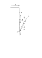
図3に示すように、ハンドル4は、台車本体2の進行方向Tの前方側に、回転中心軸Aを中心に回動自在に取り付けられている。ハンドル4は、ハンドル4の回転中心軸Aまわりの回転角度θ(操作量)を検出するためのハンドル角度検出装置14を有している。
ハンドル角度検出装置14としては、ポテンショメータを採用することができる。ハンドル角度検出装置14と制御装置5とは、電気的に接続されており、ハンドル角度検出装置14によって検出されたハンドル4の回転角度θが、制御装置5に入力される。具体的には、ポテンショメータから出力される電圧(アナログ値)が、アナログ-デジタル変換回路(A/D変換回路)を介して回転角度θ(デジタル値)に変換され、制御装置5に入力される。
また、ハンドル角度検出装置14としては角位置センサであれば他の装置も採用が可能であり、例えば、ロータリーエンコーダを使用することもできる。ロータリーエンコーダを使用する場合は、A/D変換回路の代わりにパルスカウンターボードを用いる。
ハンドル本体12は、例えば、ねじりコイルばねのような付勢部材(図示せず)によって、常に中央部分(後述する把持部37の取り付け位置)が鉛直方向上方を向くように(図3では二点鎖線で示す位置となるように)付勢されている。ハンドル本体12の付勢部材は、操作量に比例して抵抗が増し、操作力が大きくなるような操作抵抗部として機能する。これにより、ハンドル本体12は、操作者による操作がない状態で台車本体2に密着し、操作者が付勢部材の付勢力に逆らって操作することによって中央部分を進行方向Tの前方に倒すことができる。
図4に本実施形態の台車装置1のハンドル4の斜視図を示す。なお、図4に示されるハンドル本体12の回転角度は約90°である。
図4に示すように、ハンドル本体12は、断面円形の管状部材によって形成され、半円を描くように円弧状に湾曲した管形状をなしている。ハンドル本体12は、ハンドル本体12の中心軸が描く円弧(半円)の中心が、回転中心軸A上に位置するように、取り付けられている。
ハンドル本体12の両端は、台車本体2の前面において回転中心軸Aを中心に回動自在に取り付けられている。ハンドル本体12は、ハンドル本体12の両端の取り付け位置の高さが同じとなるように取り付けられている。
ここで、回転中心軸A上の幅方向Wの中心を、ハンドル中心位置Mと定義する。中心位置Mは、ハンドル本体12の中心軸が描く円弧の中心と略一致する。
図4に示すように、ハンドル本体12は、断面円形の管状部材によって形成され、半円を描くように円弧状に湾曲した管形状をなしている。ハンドル本体12は、ハンドル本体12の中心軸が描く円弧(半円)の中心が、回転中心軸A上に位置するように、取り付けられている。
ハンドル本体12の両端は、台車本体2の前面において回転中心軸Aを中心に回動自在に取り付けられている。ハンドル本体12は、ハンドル本体12の両端の取り付け位置の高さが同じとなるように取り付けられている。
ここで、回転中心軸A上の幅方向Wの中心を、ハンドル中心位置Mと定義する。中心位置Mは、ハンドル本体12の中心軸が描く円弧の中心と略一致する。
スライダー部13は、ハンドル本体12の延在方向にスライド自在に取り付けられた把持部37と、把持部37と一体に形成されたセンターステー部38と、センターステー部38に取り付けられたカム部39と、を有している。
スライダー部13は、スライダー部13をハンドル本体12に沿ってスライドさせることで、制動装置20を操作することができる制動装置20のインターフェースとして機能する。
スライダー部13は、スライダー部13をハンドル本体12に沿ってスライドさせることで、制動装置20を操作することができる制動装置20のインターフェースとして機能する。
把持部37は、円弧状に曲げられた円筒形状の部材であり、ハンドル本体12の中央部近傍に、ハンドル本体12の周面を覆うように取り付けられている。通常、ハンドル4を操作する際は、操作者は、把持部37を把持する。把持部37は、所定の付勢部材によって、ハンドル本体12の中央部に向かう方向に付勢されている。換言すれば、把持部37は、操作者による操作がない状態で、ハンドル本体12の中央部に位置し、操作者が付勢部材の付勢力に逆らって操作することによって、幅方向Wの左右のいずれかにスライドさせることができるように構成されている。
センターステー部38は、把持部37とハンドル中心位置Mとの間に延在する軸形状の部材であり、センターステー部38の第一の端部は、把持部37に接続されている。センターステー部38の第一の端部とは反対側の第二の端部は、回転中心軸Aを中心に回動自在、かつ、ハンドル中心位置Mを中心に幅方向Wに揺動自在に、台車本体2に取り付けられている。
具体的には、センターステー部38の第二の端部は、ハンドル中心位置M近傍に、球面ジョイント40を介して接続されている。即ち、センターステー部38は、ハンドル本体12の回動に伴い回転中心軸A回りに回動自在である。さらに、センターステー部38は、ハンドル本体12の回動位置(回転角度θ)に関わらず、スライダー部13のスライド移動に伴いハンドル中心位置Mを中心に揺動自在である。
球面ジョイント40は、ブラケット41と、ブラケット41に固定されているシャフト部42と、シャフト部42に回転自在に取り付けられているジョイント軸部43と、を有している。
シャフト部42は、回転中心軸Aに沿う方向に延在し、中央部に球面部44を有している。ジョイント軸部43は、シャフト部42の球面部44に面接触するように取り付けられている外輪部45と、外輪部45と一体に形成され、一方向に延在するステー部46と、を有している。ステー部46は、センターステー部38と一直線上となるように接続されている。
シャフト部42は、回転中心軸Aに沿う方向に延在し、中央部に球面部44を有している。ジョイント軸部43は、シャフト部42の球面部44に面接触するように取り付けられている外輪部45と、外輪部45と一体に形成され、一方向に延在するステー部46と、を有している。ステー部46は、センターステー部38と一直線上となるように接続されている。
マスターシリンダー36は、筒形状のシリンダー部48と、シリンダー部48内を摺動可能なロッド部49と、ロッド部49の先端に取り付けられているパッド部50と、を有している。パッド部50は、先端部側が半球面状に形成されている。マスターシリンダー36は、シリンダー部48及びロッド部49の軸方向が回転中心軸Aに沿うように、かつ、一対のマスターシリンダー36のロッド部49の先端(パッド部50)が対向するように配置されている。
カム部39は、センターステー部38の第二の端部近傍にセンターステー部38と一体に設けられ、センターステー部38(スライダー部13)の動きをマスターシリンダー36に伝達する伝達部材(カム機構)である。具体的には、カム部39は、スライダー部13の幅方向Wの移動に伴い左右に揺動するセンターステー部38の動きを、マスターシリンダー36のパッド部50に伝達する。
次に、カム部39の詳細形状について説明する。カム部39は、左右対称の形状であるため、片側の形状のみについて説明する。
カム部39は、センターステー部38からマスターシリンダー36のパッド部50方向に突出する突出部51と、突出部51の先端に形成されパッド部50に当接する斜面部52と、を有している。カム部39の斜面部52は、スライダー部13がハンドル本体12の中央に位置しているときに、マスターシリンダー36のパッド部50に当接し、スライダー部13をスライド移動させた場合に、パッド部50を介してロッド部49を押し込むように形成されている。
カム部39は、センターステー部38からマスターシリンダー36のパッド部50方向に突出する突出部51と、突出部51の先端に形成されパッド部50に当接する斜面部52と、を有している。カム部39の斜面部52は、スライダー部13がハンドル本体12の中央に位置しているときに、マスターシリンダー36のパッド部50に当接し、スライダー部13をスライド移動させた場合に、パッド部50を介してロッド部49を押し込むように形成されている。
上述したハンドル4の構成によれば、ハンドル本体12の前後方向の位置(回転角度θ)に関わらず、スライダー部13を操作することによって、制動装置20を作動させることができる。即ち、図5に示すように、スライダー部13の幅方向Wの操作によって、マスターシリンダー36のロッド部49が縮む方向に操作され、これによりマスターシリンダー36と接続された制動装置20(図2参照)が作動する。
次に、本実施形態の差動装置19の構成について説明する。図6に示すように、差動装置19は、対向する一対のサイドギヤ27と、一対のサイドギヤ27と噛み合うピニオンギヤ28とピニオンギヤ28を支持するケーシング29と、ケーシング29に一体的に設けられ、電動モーター16の駆動力によって回転する駆動歯車18と噛み合うリングギヤ30と、を有している差動歯車(ディファレンシャルギヤ)である。
一対の車軸15は、サイドギヤ27に取り付けられている。即ち、サイドギヤ27の回転に伴い、車軸15を介して車輪3が回転するように構成されている。
一対の車軸15は、サイドギヤ27に取り付けられている。即ち、サイドギヤ27の回転に伴い、車軸15を介して車輪3が回転するように構成されている。
次に、本実施形態の台車装置1の動作について説明する。
操作者は台車装置1を前進させる場合、台車本体2の前後方向及び幅方向Wに操作可能なハンドル4を進行方向T前方側に操作する。ハンドル4が操作されることにより、ハンドル角度検出装置14から制御装置5に回転角度θが入力される。制御装置5は、回転角度θに比例した速度で台車装置1が前進するように、電動モーター16を制御する。
なお、制御装置5による電動モーター16の制御方法は上述した方法に限ることはない。例えば、低速時においては、ハンドル4の回転角度θに対する速度の変化率を小さくするなどして、より滑らかに動き出すように制御してもよい。即ち、ハンドル角度θに対する速度のマッピングは自由に設定が可能である。
操作者は台車装置1を前進させる場合、台車本体2の前後方向及び幅方向Wに操作可能なハンドル4を進行方向T前方側に操作する。ハンドル4が操作されることにより、ハンドル角度検出装置14から制御装置5に回転角度θが入力される。制御装置5は、回転角度θに比例した速度で台車装置1が前進するように、電動モーター16を制御する。
なお、制御装置5による電動モーター16の制御方法は上述した方法に限ることはない。例えば、低速時においては、ハンドル4の回転角度θに対する速度の変化率を小さくするなどして、より滑らかに動き出すように制御してもよい。即ち、ハンドル角度θに対する速度のマッピングは自由に設定が可能である。
操作者は台車装置1を旋回させる場合、ハンドル4を進行方向T前方側に操作しつつスライダー部13を操作する。操作者が台車装置1を右方向に旋回させる場合、ハンドル4のスライダー部13を右方向(第一の方向)にスライドさせる。これにより、カム部39を介して進行方向Tに向かって右側のマスターシリンダー36が操作され、右側の車輪3(一方の車輪)が制動される。このとき、電動モーター16の駆動力は、差動装置19を用いて左右の車輪3に分配されているため、左側の車輪3の速度が増加され、台車装置1は右方向に旋回する。
操作者が台車装置1を左方向に旋回させる場合、ハンドル4の4スライダー部13を左方向(第一の方向とは反対の第二の方向)にスライドさせる。これにより、左側の車輪3(一方の車輪とは反対の車輪)が制動されて台車装置1は左方向に旋回する。
操作者が台車装置1を左方向に旋回させる場合、ハンドル4の4スライダー部13を左方向(第一の方向とは反対の第二の方向)にスライドさせる。これにより、左側の車輪3(一方の車輪とは反対の車輪)が制動されて台車装置1は左方向に旋回する。
上記実施形態によれば、ハンドル4を左右方向に操作することによって、台車本体2の左右旋回の操作が可能となるため、操作者はより直感的に台車装置1を操作することができる。
また、一つの電動モーター16の駆動力を差動装置19を用いて左右の車輪3に分配し、左右の車輪3のいずれかを制動することで台車本体2を曲進させる構成であるため、より低コストで、安定的な前進後退、及び左右旋回を行うことができる台車装置1を提供することができる。
また、一つの電動モーター16の駆動力を差動装置19を用いて左右の車輪3に分配し、左右の車輪3のいずれかを制動することで台車本体2を曲進させる構成であるため、より低コストで、安定的な前進後退、及び左右旋回を行うことができる台車装置1を提供することができる。
また、台車本体2が電動モーター16の駆動力によって駆動されるため、操作者の負担を軽減することができる。また、目標速度がハンドル4の操作量によって決定されるため、操作者はより直感的に台車装置1の速度を調整することが可能になる。
また、把持部37に加えられた力が球面ジョイント40(ハンドル中心位置M)を支点とした、てこの原理によって、カム部39で大きな力となるため、より小さな力で制動装置20を作動させることができる。
また、カム部39を用いることによって、より少ない構成要素でスライダー部13の動きをマスターシリンダー36に伝達することができる。
また、カム部39を用いることによって、より少ない構成要素でスライダー部13の動きをマスターシリンダー36に伝達することができる。
(第二実施形態)
以下、本発明の第二実施形態の台車装置1を図面に基づいて説明する。なお、本実施形態では、上述した第一実施形態との相違点を中心に述べ、同様の部分についてはその説明を省略する。
図7に示すように、本実施形態の台車装置1においては、スライダー部13の動きをマスターシリンダー36(制動装置20)に伝達する構造が異なる。本実施形態の台車装置1は、台車本体2の前面に幅方向Wにスライド自在に取り付けられた箱状部材54を用いてスライダー部13の動きをマスターシリンダー36に伝達している。
以下、本発明の第二実施形態の台車装置1を図面に基づいて説明する。なお、本実施形態では、上述した第一実施形態との相違点を中心に述べ、同様の部分についてはその説明を省略する。
図7に示すように、本実施形態の台車装置1においては、スライダー部13の動きをマスターシリンダー36(制動装置20)に伝達する構造が異なる。本実施形態の台車装置1は、台車本体2の前面に幅方向Wにスライド自在に取り付けられた箱状部材54を用いてスライダー部13の動きをマスターシリンダー36に伝達している。
箱状部材54は、一対の対向面55と、一対の対向面55同士を接続する接続面56と、を有している。一対の対向面55は、回転中心軸A(マスターシリンダー36のロッド部49の軸方向)と直交するように配置されている。
箱状部材54は、接続面56が台車本体2の前面と平行となるように、かつ、幅方向Wにスライド自在に、台車本体2の前面に取り付けられている。具体的には、箱状部材54は、直動ガイドのような直線運動案内部材57を介して、箱状部材54の一対の対向面55がマスターシリンダー36のパッド部50に当接するように、台車本体2に取り付けられている。
箱状部材54は、接続面56が台車本体2の前面と平行となるように、かつ、幅方向Wにスライド自在に、台車本体2の前面に取り付けられている。具体的には、箱状部材54は、直動ガイドのような直線運動案内部材57を介して、箱状部材54の一対の対向面55がマスターシリンダー36のパッド部50に当接するように、台車本体2に取り付けられている。
また、センターステー部38には、幅方向に突出する一対の箱駆動部材58が形成されている。箱駆動部材58は、幅方向Wの端部が箱状部材54の一対の対向面55の内面にそれぞれ当接するように形成されている。即ち、一対の箱駆動部材58の端部同士の距離寸法は、一対の対向面55同士の距離寸法と略同一か、一対の対向面55同士の距離寸法よりやや短くなるように形成されている。
また、箱状部材54の一対の対向面55は、ハンドル本体12がどのような位置にあっても、箱駆動部材58が当接できるように形成されている。即ち、箱状部材54の一対の対向面55は、ハンドル本体12を回動させた際の箱駆動部材58の軌跡に対応した形状を有している。
上述した構成によれば、スライダー部13が操作されることによって、箱駆動部材58を介して箱状部材54が左右に移動する。箱状部材54に移動によって、マスターシリンダー36のロッド部49が駆動される。また、一対の対向面55が、箱駆動部材58の動きに対応した形状とされていることによって、ハンドル本体12がどのような位置にあってもスライダー部13をスライドさせることによって、箱状部材54を駆動することができる。
また、一対の対向面55が、マスターシリンダー36のロッド部49の軸方向と直交するように配置されていることによって、スライダー部13の動きを確実にマスターシリンダー36に伝達することができる。
また、一対の対向面55が、マスターシリンダー36のロッド部49の軸方向と直交するように配置されていることによって、スライダー部13の動きを確実にマスターシリンダー36に伝達することができる。
(第三実施形態)
以下、本発明の第三実施形態の台車装置1を図面に基づいて説明する。
図8に示すように、本実施形態の台車装置1のセンターステー部38Cは、ジンバル機構部60によって回転中心軸Aに回動自在、かつ、幅方向Wに揺動自在に支持されている。
ジンバル機構部60は、台車本体2の前面に固定されており、第一ジンバル軸62を支持する第一ジンバルブラケット61と、第一ジンバル軸62によって回転自在に支持されている第二ジンバル軸63と、第二ジンバル軸63の両端に回転自在に取り付けられている第二ジンバルブラケット64と、を有している。センターステー部38Cは、第二ジンバルブラケット64に接続されている。
以下、本発明の第三実施形態の台車装置1を図面に基づいて説明する。
図8に示すように、本実施形態の台車装置1のセンターステー部38Cは、ジンバル機構部60によって回転中心軸Aに回動自在、かつ、幅方向Wに揺動自在に支持されている。
ジンバル機構部60は、台車本体2の前面に固定されており、第一ジンバル軸62を支持する第一ジンバルブラケット61と、第一ジンバル軸62によって回転自在に支持されている第二ジンバル軸63と、第二ジンバル軸63の両端に回転自在に取り付けられている第二ジンバルブラケット64と、を有している。センターステー部38Cは、第二ジンバルブラケット64に接続されている。
第一ジンバルブラケット61は、回転中心軸Aの幅方向W中央に固定されており、回転中心軸Aと平行に延在する第一ジンバル軸62を回転自在に支持している。即ち、第一ジンバル軸62は、台車本体2の前面に平行、かつ、水平方向に延在する回転軸である。
第二ジンバル軸63は、第一ジンバル軸62と直交するとともに、第一ジンバル軸62を中心に回転自在な軸である。第二ジンバル軸63は、所定の長さを有する円柱形状の部材であり、長手方向の中央に、第一ジンバル軸62が貫通する、貫通孔が形成されている。貫通孔は、円形の孔であり、貫通孔の中心軸が第二ジンバル軸63の中心軸に直交するように形成されている。
第二ジンバルブラケット64は、一対の対向する軸接続面65と、一対の軸接続面65とを接続するステー接続面66と、を有するU字状の部材である。第二ジンバルブラケット64は、一対の軸接続面65の対向する面が第二ジンバル軸63に接続されている。第二ジンバルブラケット64のステー接続面66は、ステー接続面66の主面が第二ジンバル軸63の中心軸と平行となるように形成されている。
センターステー部38Cの端部には、把持部37Cが接続されている。本実施形態の把持部37Cはスライド式ではない。即ち、本実施形態のハンドル4は、把持部のレールとして機能するハンドル本体を有していない。
センターステー部38Cは、所定の例えば、ねじりコイルばねのような付勢部材によって、常に把持部37Cが接続されている端部が鉛直方向上方を向くように付勢されている。また、センターステー部38Cは、所定の付勢部材によって、幅方向Wの中央部に向かう方向に付勢されている。
即ち、センターステー部38Cは、操作者により力が加えられていない状態において、把持部37Cが上方に位置し、かつ、センターステー部38Cの中心軸が鉛直方向に沿うように付勢されている。
センターステー部38Cは、所定の例えば、ねじりコイルばねのような付勢部材によって、常に把持部37Cが接続されている端部が鉛直方向上方を向くように付勢されている。また、センターステー部38Cは、所定の付勢部材によって、幅方向Wの中央部に向かう方向に付勢されている。
即ち、センターステー部38Cは、操作者により力が加えられていない状態において、把持部37Cが上方に位置し、かつ、センターステー部38Cの中心軸が鉛直方向に沿うように付勢されている。
また、ジンバル機構部60は、センターステー部38Cの幅方向Wの回転角度及び前後方向の回転角度を検知する角度検出装置を有している。さらに、本実施形態の制動装置は、電磁ブレーキによって構成されている。
本実施形態の制御装置は、センターステー部38Cの幅方向Wの回転角度に応じて電磁ブレーキを作動させるように構成されている。即ち、センターステー部38が右方向に倒された場合に、右側の車輪3を制動し、センターステー部38が左方向に倒された場合に、左側の車輪3を制動するように構成されている。
本実施形態の制御装置は、センターステー部38Cの幅方向Wの回転角度に応じて電磁ブレーキを作動させるように構成されている。即ち、センターステー部38が右方向に倒された場合に、右側の車輪3を制動し、センターステー部38が左方向に倒された場合に、左側の車輪3を制動するように構成されている。
即ち、台車本体2の前面にてセンターステー部を支持する部材は、球面ジョイントに限らず、ジンバル機構を利用することもできる。
また、ハンドルの幅方向Wの動きは、機械的な伝達機構のみならず、電気的に検知する方法も採用することができる。即ち、機械的にハンドルの動きを制動装置に伝える油圧ブレーキの代替として、電磁ブレーキの採用も可能である。
また、把持部をガイドするハンドル本体を廃する構成を採用することも可能である。
また、ハンドルの幅方向Wの動きは、機械的な伝達機構のみならず、電気的に検知する方法も採用することができる。即ち、機械的にハンドルの動きを制動装置に伝える油圧ブレーキの代替として、電磁ブレーキの採用も可能である。
また、把持部をガイドするハンドル本体を廃する構成を採用することも可能である。
上述したように、電磁ブレーキを採用することによって、例えば、曲がる方向とは反対側の車輪にも僅かに制動をかけるなどの制御も可能となる。即ち、ハンドル4Cの角度と車輪3への制動力を自由にマッピングすることも可能である。
なお、ハンドル4Cの幅方向Wの動きを第一実施形態に記載したようなカム機構のように機械的に伝達してもよい。即ち、ジンバル機構部60の第二ジンバルブラケット64又はセンターステー部38Cに第一実施形態のカム部39(図4参照)のような構造を追加するとともに、油圧ブレーキを用いて車輪を制動する構成とすることもできる。
なお、ハンドル4Cの幅方向Wの動きを第一実施形態に記載したようなカム機構のように機械的に伝達してもよい。即ち、ジンバル機構部60の第二ジンバルブラケット64又はセンターステー部38Cに第一実施形態のカム部39(図4参照)のような構造を追加するとともに、油圧ブレーキを用いて車輪を制動する構成とすることもできる。
(第四実施形態)
以下、本発明の第三実施形態の台車装置1を図面に基づいて説明する。
図9に示すように、本実施形態のハンドル4Dは、台車本体2の前面に矩形板状の力センサ68を介して取り付けられている矩形板状のベース部69と、ベース部69に取り付けられているハンドル本体12Dと、ハンドル本体12Dにスライド自在に取り付けられているスライダー部13Dと、を有している。
以下、本発明の第三実施形態の台車装置1を図面に基づいて説明する。
図9に示すように、本実施形態のハンドル4Dは、台車本体2の前面に矩形板状の力センサ68を介して取り付けられている矩形板状のベース部69と、ベース部69に取り付けられているハンドル本体12Dと、ハンドル本体12Dにスライド自在に取り付けられているスライダー部13Dと、を有している。
力センサ68は、ハンドル本体12Dに加えられる前後方向の操作力をベース部69を介して感知する板状のセンサである。力センサ68は、制御装置と接続されている。
ハンドル本体12Dは、幅方向Wに延在する水平バー部70と、水平バー部70の両端とベース部69とを接続する支持部71とを有する棒状のハンドルである。水平バー部70には、第一実施形態と同様の構成のマスターシリンダー36が取り付けられている。
ハンドル本体12Dは、幅方向Wに延在する水平バー部70と、水平バー部70の両端とベース部69とを接続する支持部71とを有する棒状のハンドルである。水平バー部70には、第一実施形態と同様の構成のマスターシリンダー36が取り付けられている。
スライダー部13はハンドル本体12Dにスライド自在に取り付けられており、その両端にはフランジ部72が形成されている。スライダー部13Dは、スライダー部13Dをスライドさせることにより、マスターシリンダー36を駆動するように構成されている。
制御装置は、ハンドル本体12Dに加えられる前後方向の操作力に基づいて台車装置1の速度を制御する。
制御装置は、ハンドル本体12Dに加えられる前後方向の操作力に基づいて台車装置1の速度を制御する。
上記実施形態によれば、板状の力センサ68を用いるとともに、マスターシリンダー36をハンドル本体12Dと一体にすることによって、ハンドル4Dをコンパクトな構造にすることができる。
以上、本発明の実施形態について図面を参照して詳述したが、各実施形態における各構成及びそれらの組み合わせ等は一例であり、本発明の趣旨から逸脱しない範囲内で、構成の付加、省略、置換、及びその他の変更が可能である。また、本発明は実施形態によって限定されることはなく、クレームの範囲によってのみ限定される。
例えば、上記実施形態においては、駆動装置として電動モーター16を有する構成としたが、車輪3を駆動する駆動装置を備えることなく、手動で台車本体2を移動させるカートにも本実施形態のハンドル4の適用は可能である。即ち、台車本体2の前後方向の移動は手動で行ってもよい。
例えば、上記実施形態においては、駆動装置として電動モーター16を有する構成としたが、車輪3を駆動する駆動装置を備えることなく、手動で台車本体2を移動させるカートにも本実施形態のハンドル4の適用は可能である。即ち、台車本体2の前後方向の移動は手動で行ってもよい。
また、上記実施形態においては、台車装置1の進行方向Tへの直進機能のみ記載したが、これに限ることはなく、台車装置1の後退機能も同様に実現することができる。
また、上記実施形態の台車装置1は、前後方向の前方側のみにハンドル4を設ける構成であるが、前方側に加え、後方側にもハンドル4を設けてもよい。即ち、台車本体2の前後にハンドル4を設けて、いずれのハンドル4による操作も可能な台車装置1としてもよい。
このような構成の台車装置1において制動装置20として油圧ブレーキを用いる場合、前方側のハンドル4とブレーキキャリパー23とを接続する系統と後方側のハンドル4とブレーキキャリパー23とを接続する系統の二系統のホース24が必要となる。この二系統の制動装置20の切り替えには電磁バルブ(ソレノイドバルブ)などの駆動弁を用いることが好ましい。
このような構成の台車装置1において制動装置20として油圧ブレーキを用いる場合、前方側のハンドル4とブレーキキャリパー23とを接続する系統と後方側のハンドル4とブレーキキャリパー23とを接続する系統の二系統のホース24が必要となる。この二系統の制動装置20の切り替えには電磁バルブ(ソレノイドバルブ)などの駆動弁を用いることが好ましい。
1 台車装置
2 台車本体
3 車輪
4,4B,4C,4D ハンドル(操作部)
5 制御装置
9 キャスター
10 駆動部収容部
12 ハンドル本体
13 スライダー部(制動ハンドル)
14 ハンドル角度検出装置
15 車軸
16 電動モーター(駆動装置)
17 出力軸
18 駆動歯車
19 差動装置
20 制動装置
22 ブレーキローター
23 ブレーキキャリパー
27 サイドギヤ
28 ピニオンギヤ
29 ケーシング
30 リングギヤ
36 マスターシリンダー
37,37C 把持部
38,38C センターステー部
39 カム部(伝達部材)
40 球面ジョイント
43 ジョイント軸部
49 ロッド部
50 パッド部
60 ジンバル機構部
A 回転軸中心
M ハンドル中心位置
P 操作点
T 進行方向
W 幅方向
X 長手方向
θ 回転角度
Claims (4)
- 一対の車輪を有する台車本体と、
前記一対の車輪に対応して設けられて、前記車輪をそれぞれ制動可能な一対の制動装置と、
前記台車本体の前後方向及び前記台車本体の幅方向に操作可能であり、前記幅方向の第一の方向に操作することで前記制動装置を介して一方の前記車輪を制動し、前記幅方向の第一の方向とは反対の第二の方向に操作することで前記制動装置を介して前記一方の車輪とは反対の車輪を制動する操作部、を有する台車装置。 - 回転駆動する出力軸を有する駆動装置と、
前記出力軸の回転数に応じた出力を前記一対の車輪に分配して前記車輪を回転させる差動装置と、
前記操作部の前後方向の操作量によって決定される目標速度に基づいて前記出力軸の回転数を設定する制御装置と、を有する請求項1に記載の台車装置。 - 前記操作部は、
前記台車本体の幅方向に亘って設けられ、前記台車本体の前後方向に操作可能なハンドル本体と、
前記ハンドル本体に対して前記台車本体の幅方向に操作可能に取り付けられている制動ハンドルと、を有する請求項1又は請求項2に記載の台車装置。 - 前記ハンドル本体は、両端が前記台車本体の前面に回動自在に取り付けられ、円弧状に湾曲した管形状をなし、
前記制動ハンドルは、前記ハンドル本体の延在方向にスライド自在に取り付けられた把持部と、
前記把持部と一体に形成され前記台車本体の前面に球面ジョイントを介して接続されたセンターステー部と、前記センターステー部に取り付けられて前記把持部の幅方向の動きを前記制動装置に伝達する伝達部材と、を有する請求項3に記載の台車装置。
Priority Applications (2)
| Application Number | Priority Date | Filing Date | Title |
|---|---|---|---|
| JP2016530781A JP6126748B2 (ja) | 2014-07-04 | 2014-07-04 | 台車装置 |
| PCT/JP2014/067905 WO2016002067A1 (ja) | 2014-07-04 | 2014-07-04 | 台車装置 |
Applications Claiming Priority (1)
| Application Number | Priority Date | Filing Date | Title |
|---|---|---|---|
| PCT/JP2014/067905 WO2016002067A1 (ja) | 2014-07-04 | 2014-07-04 | 台車装置 |
Publications (1)
| Publication Number | Publication Date |
|---|---|
| WO2016002067A1 true WO2016002067A1 (ja) | 2016-01-07 |
Family
ID=55018664
Family Applications (1)
| Application Number | Title | Priority Date | Filing Date |
|---|---|---|---|
| PCT/JP2014/067905 Ceased WO2016002067A1 (ja) | 2014-07-04 | 2014-07-04 | 台車装置 |
Country Status (2)
| Country | Link |
|---|---|
| JP (1) | JP6126748B2 (ja) |
| WO (1) | WO2016002067A1 (ja) |
Cited By (3)
| Publication number | Priority date | Publication date | Assignee | Title |
|---|---|---|---|---|
| JP2018127019A (ja) * | 2017-02-06 | 2018-08-16 | エレクター株式会社 | 台車装置 |
| JP2018184016A (ja) * | 2017-04-24 | 2018-11-22 | 清水建設株式会社 | 搬送台車 |
| US11904924B1 (en) * | 2022-07-27 | 2024-02-20 | Logistics And Supply Chain Multitech R & D Centre Limited | Motorised trolley |
Citations (2)
| Publication number | Priority date | Publication date | Assignee | Title |
|---|---|---|---|---|
| JPH04143172A (ja) * | 1990-10-05 | 1992-05-18 | Yaskawa Electric Corp | 電動カート |
| JP2008114630A (ja) * | 2006-11-01 | 2008-05-22 | Hoshizaki Electric Co Ltd | 補助電動機能付配膳車 |
-
2014
- 2014-07-04 WO PCT/JP2014/067905 patent/WO2016002067A1/ja not_active Ceased
- 2014-07-04 JP JP2016530781A patent/JP6126748B2/ja active Active
Patent Citations (2)
| Publication number | Priority date | Publication date | Assignee | Title |
|---|---|---|---|---|
| JPH04143172A (ja) * | 1990-10-05 | 1992-05-18 | Yaskawa Electric Corp | 電動カート |
| JP2008114630A (ja) * | 2006-11-01 | 2008-05-22 | Hoshizaki Electric Co Ltd | 補助電動機能付配膳車 |
Cited By (3)
| Publication number | Priority date | Publication date | Assignee | Title |
|---|---|---|---|---|
| JP2018127019A (ja) * | 2017-02-06 | 2018-08-16 | エレクター株式会社 | 台車装置 |
| JP2018184016A (ja) * | 2017-04-24 | 2018-11-22 | 清水建設株式会社 | 搬送台車 |
| US11904924B1 (en) * | 2022-07-27 | 2024-02-20 | Logistics And Supply Chain Multitech R & D Centre Limited | Motorised trolley |
Also Published As
| Publication number | Publication date |
|---|---|
| JPWO2016002067A1 (ja) | 2017-05-25 |
| JP6126748B2 (ja) | 2017-05-10 |
Similar Documents
| Publication | Publication Date | Title |
|---|---|---|
| US9889874B1 (en) | Three-axis motion joystick | |
| CN108137079B (zh) | 用于车辆的可缩回且可移出的转向装置 | |
| JP5683876B2 (ja) | ステアバイワイヤー装置 | |
| JP4387935B2 (ja) | 車両用操作装置 | |
| JP4590568B2 (ja) | 走行形態切換え装置および制御方法 | |
| US10308114B2 (en) | Hand control throttle system | |
| JP6126748B2 (ja) | 台車装置 | |
| JP6837910B2 (ja) | 全方向移動車両 | |
| JP6490214B2 (ja) | 台車装置 | |
| KR20190066973A (ko) | 배관 주행 로봇 | |
| JP3656500B2 (ja) | 全方向移動型台車 | |
| JP6072975B2 (ja) | 台車装置 | |
| CN103547502B (zh) | 用于使车辆转向的操作装置和用于使车辆转向的方法 | |
| JP4641432B2 (ja) | ハンドル装置 | |
| JP2007313984A (ja) | 車両の操舵機構 | |
| JP2008001273A (ja) | 走行台車の操向装置 | |
| JP2017217993A (ja) | ステアリングスイッチ装置 | |
| JP6865412B2 (ja) | 台車装置 | |
| JPH09173327A (ja) | 移動形x線装置用電動台車の操作装置 | |
| JP4680845B2 (ja) | 車両用運転装置 | |
| JP2007075479A (ja) | 走行アシスト機能付き片手用車椅子 | |
| KR102832849B1 (ko) | 휠체어 | |
| JP2008090773A (ja) | 操作装置及び操作装置を備える移動体 | |
| KR101755885B1 (ko) | Atv 제어기구장치 | |
| JP2018143024A (ja) | 電動車両のアクセル装置 |
Legal Events
| Date | Code | Title | Description |
|---|---|---|---|
| 121 | Ep: the epo has been informed by wipo that ep was designated in this application |
Ref document number: 14896759 Country of ref document: EP Kind code of ref document: A1 |
|
| ENP | Entry into the national phase |
Ref document number: 2016530781 Country of ref document: JP Kind code of ref document: A |
|
| NENP | Non-entry into the national phase |
Ref country code: DE |
|
| 122 | Ep: pct application non-entry in european phase |
Ref document number: 14896759 Country of ref document: EP Kind code of ref document: A1 |