WO2015199217A1 - Method for manufacturing long polarizer - Google Patents
Method for manufacturing long polarizer Download PDFInfo
- Publication number
- WO2015199217A1 WO2015199217A1 PCT/JP2015/068504 JP2015068504W WO2015199217A1 WO 2015199217 A1 WO2015199217 A1 WO 2015199217A1 JP 2015068504 W JP2015068504 W JP 2015068504W WO 2015199217 A1 WO2015199217 A1 WO 2015199217A1
- Authority
- WO
- WIPO (PCT)
- Prior art keywords
- polarizer
- protective film
- manufacturing
- polarizing
- long
- Prior art date
Links
Images


Classifications
-
- B—PERFORMING OPERATIONS; TRANSPORTING
- B29—WORKING OF PLASTICS; WORKING OF SUBSTANCES IN A PLASTIC STATE IN GENERAL
- B29D—PRODUCING PARTICULAR ARTICLES FROM PLASTICS OR FROM SUBSTANCES IN A PLASTIC STATE
- B29D11/00—Producing optical elements, e.g. lenses or prisms
- B29D11/00634—Production of filters
- B29D11/00644—Production of filters polarizing
-
- B—PERFORMING OPERATIONS; TRANSPORTING
- B29—WORKING OF PLASTICS; WORKING OF SUBSTANCES IN A PLASTIC STATE IN GENERAL
- B29C—SHAPING OR JOINING OF PLASTICS; SHAPING OF MATERIAL IN A PLASTIC STATE, NOT OTHERWISE PROVIDED FOR; AFTER-TREATMENT OF THE SHAPED PRODUCTS, e.g. REPAIRING
- B29C55/00—Shaping by stretching, e.g. drawing through a die; Apparatus therefor
- B29C55/02—Shaping by stretching, e.g. drawing through a die; Apparatus therefor of plates or sheets
- B29C55/023—Shaping by stretching, e.g. drawing through a die; Apparatus therefor of plates or sheets using multilayered plates or sheets
-
- B—PERFORMING OPERATIONS; TRANSPORTING
- B29—WORKING OF PLASTICS; WORKING OF SUBSTANCES IN A PLASTIC STATE IN GENERAL
- B29C—SHAPING OR JOINING OF PLASTICS; SHAPING OF MATERIAL IN A PLASTIC STATE, NOT OTHERWISE PROVIDED FOR; AFTER-TREATMENT OF THE SHAPED PRODUCTS, e.g. REPAIRING
- B29C55/00—Shaping by stretching, e.g. drawing through a die; Apparatus therefor
- B29C55/02—Shaping by stretching, e.g. drawing through a die; Apparatus therefor of plates or sheets
- B29C55/04—Shaping by stretching, e.g. drawing through a die; Apparatus therefor of plates or sheets uniaxial, e.g. oblique
- B29C55/06—Shaping by stretching, e.g. drawing through a die; Apparatus therefor of plates or sheets uniaxial, e.g. oblique parallel with the direction of feed
- B29C55/065—Shaping by stretching, e.g. drawing through a die; Apparatus therefor of plates or sheets uniaxial, e.g. oblique parallel with the direction of feed in several stretching steps
-
- B—PERFORMING OPERATIONS; TRANSPORTING
- B32—LAYERED PRODUCTS
- B32B—LAYERED PRODUCTS, i.e. PRODUCTS BUILT-UP OF STRATA OF FLAT OR NON-FLAT, e.g. CELLULAR OR HONEYCOMB, FORM
- B32B27/00—Layered products comprising a layer of synthetic resin
- B32B27/06—Layered products comprising a layer of synthetic resin as the main or only constituent of a layer, which is next to another layer of the same or of a different material
- B32B27/08—Layered products comprising a layer of synthetic resin as the main or only constituent of a layer, which is next to another layer of the same or of a different material of synthetic resin
-
- B—PERFORMING OPERATIONS; TRANSPORTING
- B32—LAYERED PRODUCTS
- B32B—LAYERED PRODUCTS, i.e. PRODUCTS BUILT-UP OF STRATA OF FLAT OR NON-FLAT, e.g. CELLULAR OR HONEYCOMB, FORM
- B32B27/00—Layered products comprising a layer of synthetic resin
- B32B27/30—Layered products comprising a layer of synthetic resin comprising vinyl (co)polymers; comprising acrylic (co)polymers
- B32B27/306—Layered products comprising a layer of synthetic resin comprising vinyl (co)polymers; comprising acrylic (co)polymers comprising vinyl acetate or vinyl alcohol (co)polymers
-
- B—PERFORMING OPERATIONS; TRANSPORTING
- B32—LAYERED PRODUCTS
- B32B—LAYERED PRODUCTS, i.e. PRODUCTS BUILT-UP OF STRATA OF FLAT OR NON-FLAT, e.g. CELLULAR OR HONEYCOMB, FORM
- B32B27/00—Layered products comprising a layer of synthetic resin
- B32B27/36—Layered products comprising a layer of synthetic resin comprising polyesters
-
- B—PERFORMING OPERATIONS; TRANSPORTING
- B32—LAYERED PRODUCTS
- B32B—LAYERED PRODUCTS, i.e. PRODUCTS BUILT-UP OF STRATA OF FLAT OR NON-FLAT, e.g. CELLULAR OR HONEYCOMB, FORM
- B32B3/00—Layered products comprising a layer with external or internal discontinuities or unevennesses, or a layer of non-planar form; Layered products having particular features of form
- B32B3/26—Layered products comprising a layer with external or internal discontinuities or unevennesses, or a layer of non-planar form; Layered products having particular features of form characterised by a particular shape of the outline of the cross-section of a continuous layer; characterised by a layer with cavities or internal voids ; characterised by an apertured layer
- B32B3/266—Layered products comprising a layer with external or internal discontinuities or unevennesses, or a layer of non-planar form; Layered products having particular features of form characterised by a particular shape of the outline of the cross-section of a continuous layer; characterised by a layer with cavities or internal voids ; characterised by an apertured layer characterised by an apertured layer, the apertures going through the whole thickness of the layer, e.g. expanded metal, perforated layer, slit layer regular cells B32B3/12
-
- B—PERFORMING OPERATIONS; TRANSPORTING
- B32—LAYERED PRODUCTS
- B32B—LAYERED PRODUCTS, i.e. PRODUCTS BUILT-UP OF STRATA OF FLAT OR NON-FLAT, e.g. CELLULAR OR HONEYCOMB, FORM
- B32B37/00—Methods or apparatus for laminating, e.g. by curing or by ultrasonic bonding
- B32B37/14—Methods or apparatus for laminating, e.g. by curing or by ultrasonic bonding characterised by the properties of the layers
- B32B37/16—Methods or apparatus for laminating, e.g. by curing or by ultrasonic bonding characterised by the properties of the layers with all layers existing as coherent layers before laminating
- B32B37/20—Methods or apparatus for laminating, e.g. by curing or by ultrasonic bonding characterised by the properties of the layers with all layers existing as coherent layers before laminating involving the assembly of continuous webs only
- B32B37/203—One or more of the layers being plastic
-
- G—PHYSICS
- G02—OPTICS
- G02B—OPTICAL ELEMENTS, SYSTEMS OR APPARATUS
- G02B1/00—Optical elements characterised by the material of which they are made; Optical coatings for optical elements
- G02B1/10—Optical coatings produced by application to, or surface treatment of, optical elements
- G02B1/14—Protective coatings, e.g. hard coatings
-
- G—PHYSICS
- G02—OPTICS
- G02B—OPTICAL ELEMENTS, SYSTEMS OR APPARATUS
- G02B5/00—Optical elements other than lenses
- G02B5/30—Polarising elements
- G02B5/3025—Polarisers, i.e. arrangements capable of producing a definite output polarisation state from an unpolarised input state
- G02B5/3033—Polarisers, i.e. arrangements capable of producing a definite output polarisation state from an unpolarised input state in the form of a thin sheet or foil, e.g. Polaroid
- G02B5/3041—Polarisers, i.e. arrangements capable of producing a definite output polarisation state from an unpolarised input state in the form of a thin sheet or foil, e.g. Polaroid comprising multiple thin layers, e.g. multilayer stacks
-
- B—PERFORMING OPERATIONS; TRANSPORTING
- B29—WORKING OF PLASTICS; WORKING OF SUBSTANCES IN A PLASTIC STATE IN GENERAL
- B29K—INDEXING SCHEME ASSOCIATED WITH SUBCLASSES B29B, B29C OR B29D, RELATING TO MOULDING MATERIALS OR TO MATERIALS FOR MOULDS, REINFORCEMENTS, FILLERS OR PREFORMED PARTS, e.g. INSERTS
- B29K2629/00—Use of polyvinylalcohols, polyvinylethers, polyvinylaldehydes, polyvinylketones or polyvinylketals or derivatives thereof, for preformed parts, e.g. for inserts
- B29K2629/04—PVOH, i.e. polyvinyl alcohol
-
- B—PERFORMING OPERATIONS; TRANSPORTING
- B29—WORKING OF PLASTICS; WORKING OF SUBSTANCES IN A PLASTIC STATE IN GENERAL
- B29K—INDEXING SCHEME ASSOCIATED WITH SUBCLASSES B29B, B29C OR B29D, RELATING TO MOULDING MATERIALS OR TO MATERIALS FOR MOULDS, REINFORCEMENTS, FILLERS OR PREFORMED PARTS, e.g. INSERTS
- B29K2667/00—Use of polyesters or derivatives thereof for preformed parts, e.g. for inserts
- B29K2667/003—PET, i.e. poylethylene terephthalate
-
- B—PERFORMING OPERATIONS; TRANSPORTING
- B32—LAYERED PRODUCTS
- B32B—LAYERED PRODUCTS, i.e. PRODUCTS BUILT-UP OF STRATA OF FLAT OR NON-FLAT, e.g. CELLULAR OR HONEYCOMB, FORM
- B32B38/00—Ancillary operations in connection with laminating processes
- B32B38/0012—Mechanical treatment, e.g. roughening, deforming, stretching
- B32B2038/0028—Stretching, elongating
-
- B—PERFORMING OPERATIONS; TRANSPORTING
- B32—LAYERED PRODUCTS
- B32B—LAYERED PRODUCTS, i.e. PRODUCTS BUILT-UP OF STRATA OF FLAT OR NON-FLAT, e.g. CELLULAR OR HONEYCOMB, FORM
- B32B38/00—Ancillary operations in connection with laminating processes
- B32B38/04—Punching, slitting or perforating
- B32B2038/047—Perforating
-
- B—PERFORMING OPERATIONS; TRANSPORTING
- B32—LAYERED PRODUCTS
- B32B—LAYERED PRODUCTS, i.e. PRODUCTS BUILT-UP OF STRATA OF FLAT OR NON-FLAT, e.g. CELLULAR OR HONEYCOMB, FORM
- B32B2250/00—Layers arrangement
- B32B2250/02—2 layers
-
- B—PERFORMING OPERATIONS; TRANSPORTING
- B32—LAYERED PRODUCTS
- B32B—LAYERED PRODUCTS, i.e. PRODUCTS BUILT-UP OF STRATA OF FLAT OR NON-FLAT, e.g. CELLULAR OR HONEYCOMB, FORM
- B32B2250/00—Layers arrangement
- B32B2250/24—All layers being polymeric
-
- B—PERFORMING OPERATIONS; TRANSPORTING
- B32—LAYERED PRODUCTS
- B32B—LAYERED PRODUCTS, i.e. PRODUCTS BUILT-UP OF STRATA OF FLAT OR NON-FLAT, e.g. CELLULAR OR HONEYCOMB, FORM
- B32B2307/00—Properties of the layers or laminate
- B32B2307/40—Properties of the layers or laminate having particular optical properties
- B32B2307/42—Polarizing, birefringent, filtering
-
- B—PERFORMING OPERATIONS; TRANSPORTING
- B32—LAYERED PRODUCTS
- B32B—LAYERED PRODUCTS, i.e. PRODUCTS BUILT-UP OF STRATA OF FLAT OR NON-FLAT, e.g. CELLULAR OR HONEYCOMB, FORM
- B32B2309/00—Parameters for the laminating or treatment process; Apparatus details
- B32B2309/08—Dimensions, e.g. volume
- B32B2309/10—Dimensions, e.g. volume linear, e.g. length, distance, width
- B32B2309/105—Thickness
-
- B—PERFORMING OPERATIONS; TRANSPORTING
- B32—LAYERED PRODUCTS
- B32B—LAYERED PRODUCTS, i.e. PRODUCTS BUILT-UP OF STRATA OF FLAT OR NON-FLAT, e.g. CELLULAR OR HONEYCOMB, FORM
- B32B2329/00—Polyvinylalcohols, polyvinylethers, polyvinylaldehydes, polyvinylketones or polyvinylketals
- B32B2329/04—Polyvinylalcohol
-
- B—PERFORMING OPERATIONS; TRANSPORTING
- B32—LAYERED PRODUCTS
- B32B—LAYERED PRODUCTS, i.e. PRODUCTS BUILT-UP OF STRATA OF FLAT OR NON-FLAT, e.g. CELLULAR OR HONEYCOMB, FORM
- B32B2367/00—Polyesters, e.g. PET, i.e. polyethylene terephthalate
-
- B—PERFORMING OPERATIONS; TRANSPORTING
- B32—LAYERED PRODUCTS
- B32B—LAYERED PRODUCTS, i.e. PRODUCTS BUILT-UP OF STRATA OF FLAT OR NON-FLAT, e.g. CELLULAR OR HONEYCOMB, FORM
- B32B2457/00—Electrical equipment
- B32B2457/20—Displays, e.g. liquid crystal displays, plasma displays
-
- B—PERFORMING OPERATIONS; TRANSPORTING
- B32—LAYERED PRODUCTS
- B32B—LAYERED PRODUCTS, i.e. PRODUCTS BUILT-UP OF STRATA OF FLAT OR NON-FLAT, e.g. CELLULAR OR HONEYCOMB, FORM
- B32B37/00—Methods or apparatus for laminating, e.g. by curing or by ultrasonic bonding
- B32B37/02—Methods or apparatus for laminating, e.g. by curing or by ultrasonic bonding characterised by a sequence of laminating steps, e.g. by adding new layers at consecutive laminating stations
-
- B—PERFORMING OPERATIONS; TRANSPORTING
- B32—LAYERED PRODUCTS
- B32B—LAYERED PRODUCTS, i.e. PRODUCTS BUILT-UP OF STRATA OF FLAT OR NON-FLAT, e.g. CELLULAR OR HONEYCOMB, FORM
- B32B37/00—Methods or apparatus for laminating, e.g. by curing or by ultrasonic bonding
- B32B37/14—Methods or apparatus for laminating, e.g. by curing or by ultrasonic bonding characterised by the properties of the layers
- B32B37/144—Methods or apparatus for laminating, e.g. by curing or by ultrasonic bonding characterised by the properties of the layers using layers with different mechanical or chemical conditions or properties, e.g. layers with different thermal shrinkage, layers under tension during bonding
-
- B—PERFORMING OPERATIONS; TRANSPORTING
- B32—LAYERED PRODUCTS
- B32B—LAYERED PRODUCTS, i.e. PRODUCTS BUILT-UP OF STRATA OF FLAT OR NON-FLAT, e.g. CELLULAR OR HONEYCOMB, FORM
- B32B38/00—Ancillary operations in connection with laminating processes
- B32B38/10—Removing layers, or parts of layers, mechanically or chemically
-
- B—PERFORMING OPERATIONS; TRANSPORTING
- B32—LAYERED PRODUCTS
- B32B—LAYERED PRODUCTS, i.e. PRODUCTS BUILT-UP OF STRATA OF FLAT OR NON-FLAT, e.g. CELLULAR OR HONEYCOMB, FORM
- B32B38/00—Ancillary operations in connection with laminating processes
- B32B38/18—Handling of layers or the laminate
- B32B38/1825—Handling of layers or the laminate characterised by the control or constructional features of devices for tensioning, stretching or registration
Definitions
- the present invention relates to a method for producing a long polarizer. More specifically, the present invention relates to a method for manufacturing a long polarizer having non-polarizing portions arranged in a predetermined pattern.
- the present invention has been made to solve the above-described conventional problems, and its main purpose is to realize multi-functionality and high-functionality of electronic devices such as image display apparatuses, and there is variation in quality.
- Another object of the present invention is to provide a method for producing a long polarizer that can produce a polarizer as a final product without cost and with high productivity.
- a method for producing a long polarizer having a non-polarizing portion is provided.
- a long surface protective film having through holes arranged at predetermined intervals in the long direction and / or the width direction is laminated on one surface of a long polarizer, Forming a linear polarizing film laminate; partially decolorizing the polarizer through a through-hole of the surface protective film to form a non-polarizing portion; and removing the surface protective film ;including.
- the through holes are arranged at predetermined intervals in the longitudinal direction. In one embodiment, the through holes are arranged at substantially equal intervals in at least the longitudinal direction.
- the decolorization is performed by immersing the polarizer in a basic solution.
- the said manufacturing method forms a recessed part in the said surface protection film side of the said polarizer by the said decoloring.
- the said non-polarizing part formed by the said decoloring is a low concentration part in which content of a dichroic substance is lower than another site
- the reduction of the dichroic substance is performed such that the content of the dichroic substance in the low concentration portion is 0.2% by weight or less.
- the manufacturing method reduces the alkali metal and / or alkaline earth metal contained in the polarizer at the contact portion where the basic solution of the polarizer is contacted after the decolorization. Further comprising.
- a long surface protective film having through holes arranged at predetermined intervals in the long direction and / or the width direction is provided on one surface of a long polarizer.
- the “elongate shape” means an elongated shape having a sufficiently long length with respect to the width, for example, an elongated shape having a length of 10 times or more, preferably 20 times or more with respect to the width. Including.
- the polarizer before forming a non-polarization part is an intermediate body of the polarizer which has a non-polarization part obtained by the manufacturing method of this invention strictly, it is only called a polarizer in this specification.
- polarizer means an intermediate or a polarizer having a non-polarization part obtained by the production method of the present invention. be able to.
- A-1-1 Preparation of laminate of resin substrate / PVA resin layer
- a PVA resin layer is formed on a resin substrate by applying a coating liquid containing a PVA resin and drying it.
- a laminate of PVA resin layers is prepared.
- the water absorption rate of the resin base material can be adjusted, for example, by introducing a modifying group into the forming material.
- the water absorption is a value determined according to JIS K 7209.
- the thickness of the resin base material before stretching is preferably 20 ⁇ m to 300 ⁇ m, more preferably 50 ⁇ m to 200 ⁇ m. If it is less than 20 ⁇ m, it may be difficult to form a PVA-based resin layer. If it exceeds 300 ⁇ m, for example, in stretching in water, it takes a long time for the resin base material to absorb water, and an excessive load may be required for stretching.
- the average degree of polymerization of the PVA resin can be appropriately selected according to the purpose.
- the average degree of polymerization is usually 1000 to 10,000, preferably 1200 to 4500, and more preferably 1500 to 4300.
- the average degree of polymerization can be determined according to JIS K 6726-1994.
- the laminate When employing an underwater stretching method, it is preferable to stretch the laminate by immersing it in an aqueous boric acid solution (stretching in boric acid in water).
- an aqueous boric acid solution as the stretching bath, the PVA resin layer can be provided with rigidity that can withstand the tension applied during stretching and water resistance that does not dissolve in water.
- boric acid can form a tetrahydroxyborate anion in an aqueous solution and crosslink with a PVA resin by hydrogen bonding.
- rigidity and water resistance can be imparted to the PVA-based resin layer, the film can be stretched well, and a polarizer having excellent optical characteristics can be produced.
- the laminate may be appropriately subjected to treatment for using the PVA resin layer as a polarizer.
- the treatment for obtaining a polarizer include insolubilization treatment, crosslinking treatment, washing treatment, and drying treatment.
- count, order, etc. of these processes are not specifically limited.
- a protective film is bonded to the polarizer surface of the resin base material / polarizer laminate, the resin base material is then peeled off, and further separated from the release surface of the resin base material as necessary.
- the protective film can be bonded. Bonding of the protective film can be typically performed by roll-to-roll.
- the manufacturing method of the present invention can also be a manufacturing method of a long polarizing plate including a polarizer having a non-polarizing portion.
- roll to roll means aligning and sticking together each other's elongate direction, conveying a roll-shaped film.
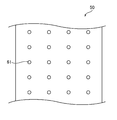
- FIG. 3 is a schematic cross-sectional view of the polarizing film laminate obtained as described above.
- the exposed portion 51 where the polarizer 10 is exposed is defined by the through hole 61 of the first surface protective film 50.
- borate As a metal salt which can produce
- the borate can be generated by neutralizing boric acid contained in the resin film with a basic solution (a solution of an alkali metal hydroxide and / or an alkaline earth metal hydroxide).
- the borate (metaborate) can be hydrolyzed to generate hydroxide ions as shown in the following formula, for example, when a polarizer is placed in a humidified environment. (Wherein X represents an alkali metal or alkaline earth metal)
- a method of bringing the treatment liquid into contact with the basic solution is preferably used. According to such a method, the content of the alkali metal and / or alkaline earth metal can be reduced by transferring the alkali metal and / or alkaline earth metal from the resin film to the treatment liquid.
- Examples of acidic compounds that can satisfy the above pKa include hydrochloric acid (pKa: -3.7), sulfuric acid (pK 2 : 1.96), nitric acid (pKa: -1.8), hydrogen fluoride (pKa: 3 .17), inorganic acids such as boric acid (pKa: 9.2), formic acid (pKa: 3.54), oxalic acid (pK 1 : 1.04, pK 2 : 3.82), citric acid (pK 1 : 3.09, pK 2 : 4.75, pK 3 : 6.41), acetic acid (pKa: 4.8), benzoic acid (pKa: 4.0), and other organic acids.
- hydrochloric acid pKa: -3.7
- sulfuric acid pK 2 : 1.96
- nitric acid pKa: -1.8
- hydrogen fluoride pKa: 3 .17
- inorganic acids such as boric acid (pK
- the above polarizer piece means a polarizer obtained by cutting a long polarizer.
- the polarizer piece may be simply referred to as a polarizer in the context.
- the non-polarizing portion is a low concentration portion where the content of the dichroic material is relatively low.
- the low-concentration part has a lower dichroic substance content than other parts.
- the non-polarizing portion is formed mechanically (for example, by a method of mechanically cutting off using a sculpture blade punching, a plotter, a water jet, etc.), a crack, Quality problems such as delamination (delamination) and paste sticking are avoided.
- the content of the dichroic substance itself is low in the low-concentration part, the transparency of the non-polarizing part is higher than when the non-polarizing part is formed by decomposing the dichroic substance with laser light or the like. Maintained well.
- the polarizer can be provided as a polarizing plate practically.
- the polarizing plate has a polarizer and a protective film disposed on at least one side of the polarizer (not shown).
- the polarizing plate has an adhesive layer as the outermost layer.
- the pressure-sensitive adhesive layer is typically the outermost layer on the image display device side.
- a separator is temporarily attached to the pressure-sensitive adhesive layer so as to be peeled off, and the pressure-sensitive adhesive layer is protected until actual use, and roll formation is possible.
- the polarizer is subjected to cutting to the predetermined size in the state of a polarizing plate.
- the polarizing plate is cut to a predetermined size and used to produce a plurality of polarizing plate pieces each having a polarizer having a non-polarizing portion and a protective film disposed on at least one side of the polarizer. It is done.
- the pressure-sensitive adhesive ester resin film with through-holes formed thereon is bonded to the polarizer surface of the obtained polarizing plate by roll-to-roll, and this is immersed in a 1 mol / L (1N) sodium hydroxide aqueous solution for 180 seconds. Then, it was immersed in 1 mol / L (1N) hydrochloric acid for 60 seconds. Then, it dried at 60 degreeC and formed the transparent part in the polarizer.
Abstract
Description
1つの実施形態においては、上記貫通孔は、上記長尺方向に所定の間隔で配置されている。
1つの実施形態においては、上記貫通孔は、少なくとも上記長尺方向に実質的に等間隔で配置されている。
1つの実施形態においては、上記貫通孔は、上記長尺方向および上記幅方向に実質的に等間隔で配置されている。
1つの実施形態においては、上記貫通孔はドット状に配置されている。
1つの実施形態においては、上記貫通孔の平面視形状は、略円形状または略矩形状である。
1つの実施形態においては、上記脱色は、上記偏光子を塩基性溶液に接触させることにより行われる。
1つの実施形態においては、上記偏光フィルム積層体は、上記長尺状の偏光子の他方の面に長尺状の保護フィルムが配置されている。
1つの実施形態においては、上記製造方法は、上記脱色の前に上記長尺状の偏光子の他方の面の最外部に長尺状の第2の表面保護フィルムを積層すること、および、該脱色の後に該第2の表面保護フィルムを除去することをさらに含む。1つの実施形態においては、上記脱色は、上記偏光子を塩基性溶液に浸漬することにより行われる。
1つの実施形態においては、上記製造方法は、上記脱色により、上記偏光子の上記表面保護フィルム側に凹部を形成する。
1つの実施形態においては、上記脱色により形成される上記非偏光部は、他の部位よりも二色性物質の含有量が低い低濃度部である。
1つの実施形態においては、上記二色性物質の低減は、上記低濃度部における二色性物質の含有量が0.2重量%以下となるようにして行われる。
1つの実施形態においては、上記製造方法は、上記脱色の後、上記偏光子の上記塩基性溶液を接触させた接触部において、該偏光子に含まれるアルカリ金属および/またはアルカリ土類金属を低減させることをさらに含む。
1つの実施形態においては、上記アルカリ金属および/またはアルカリ土類金属の低減は、上記接触部におけるアルカリ金属および/またはアルカリ土類金属の含有量が3.6重量%以下となるようにして行われる。
1つの実施形態においては、上記偏光子の厚みは10μm以下である。
1つの実施形態においては、上記保護フィルムの厚みは80μm以下である。 According to the embodiment of the present invention, a method for producing a long polarizer having a non-polarizing portion is provided. In this manufacturing method, a long surface protective film having through holes arranged at predetermined intervals in the long direction and / or the width direction is laminated on one surface of a long polarizer, Forming a linear polarizing film laminate; partially decolorizing the polarizer through a through-hole of the surface protective film to form a non-polarizing portion; and removing the surface protective film ;including.
In one embodiment, the through holes are arranged at predetermined intervals in the longitudinal direction.
In one embodiment, the through holes are arranged at substantially equal intervals in at least the longitudinal direction.
In one embodiment, the through holes are arranged at substantially equal intervals in the longitudinal direction and the width direction.
In one embodiment, the through hole is arranged in a dot shape.
In one embodiment, the planar view shape of the said through-hole is a substantially circular shape or a substantially rectangular shape.
In one embodiment, the decolorization is performed by bringing the polarizer into contact with a basic solution.
In one embodiment, the said polarizing film laminated body has the elongate protective film arrange | positioned at the other surface of the said elongate polarizer.
In one embodiment, the manufacturing method comprises: laminating a long second surface protective film on the outermost surface of the other surface of the long polarizer before the decolorization; and The method further includes removing the second surface protective film after decolorization. In one embodiment, the decolorization is performed by immersing the polarizer in a basic solution.
In one embodiment, the said manufacturing method forms a recessed part in the said surface protection film side of the said polarizer by the said decoloring.
In one embodiment, the said non-polarizing part formed by the said decoloring is a low concentration part in which content of a dichroic substance is lower than another site | part.
In one embodiment, the reduction of the dichroic substance is performed such that the content of the dichroic substance in the low concentration portion is 0.2% by weight or less.
In one embodiment, the manufacturing method reduces the alkali metal and / or alkaline earth metal contained in the polarizer at the contact portion where the basic solution of the polarizer is contacted after the decolorization. Further comprising.
In one embodiment, the reduction of the alkali metal and / or alkaline earth metal is performed such that the content of the alkali metal and / or alkaline earth metal in the contact portion is 3.6% by weight or less. Is called.
In one embodiment, the thickness of the polarizer is 10 μm or less.
In one embodiment, the thickness of the said protective film is 80 micrometers or less.
A-1.偏光子の作製
偏光子としては、任意の適切な偏光子が採用され得る。偏光子は、代表的には樹脂フィルムで構成される。樹脂フィルムは、代表的には、二色性物質を含むポリビニルアルコール系樹脂(以下、「PVA系樹脂」と称する)フィルムである。偏光子を構成する樹脂フィルム(代表的には、PVA系樹脂フィルム)は、単一のフィルムであってもよく、樹脂基材上に形成された樹脂層(代表的には、PVA系樹脂層)であってもよい。PVA系樹脂層は、樹脂基材上にPVA系樹脂を含む塗布液を塗布して形成してもよく、樹脂基材上にPVA系樹脂フィルムを積層して形成してもよい。以下、代表例として、偏光子が樹脂基材上に形成されたPVA系樹脂層である場合について具体的に説明する。ここではPVA系樹脂層が塗布形成される場合について説明するが、PVA系樹脂フィルムを積層する場合についても同様である。なお、偏光子が単一のPVA系樹脂フィルムである場合には、偏光子は当業界で周知慣用されている方法により作製され得るので、詳細な説明は省略する。 A. Production of polarizing film laminate A-1. Production of Polarizer Any appropriate polarizer may be adopted as the polarizer. The polarizer is typically composed of a resin film. The resin film is typically a polyvinyl alcohol-based resin (hereinafter referred to as “PVA-based resin”) film containing a dichroic substance. The resin film (typically, PVA resin film) constituting the polarizer may be a single film, or a resin layer (typically, PVA resin layer) formed on the resin substrate. ). The PVA-based resin layer may be formed by applying a coating solution containing a PVA-based resin on a resin substrate, or may be formed by laminating a PVA-based resin film on a resin substrate. Hereinafter, the case where a polarizer is a PVA-type resin layer formed on the resin base material is demonstrated concretely as a representative example. Here, the case where the PVA resin layer is applied and formed will be described, but the same applies to the case where the PVA resin film is laminated. In addition, when a polarizer is a single PVA-type resin film, since a polarizer can be produced by the method well-known and used in this industry, detailed description is abbreviate | omitted.
最初に、樹脂基材上に、PVA系樹脂を含む塗布液を塗布し乾燥することにより、PVA系樹脂層を形成して、樹脂基材/PVA系樹脂層の積層体を作製する。 A-1-1. Preparation of laminate of resin substrate / PVA resin layer First, a PVA resin layer is formed on a resin substrate by applying a coating liquid containing a PVA resin and drying it. A laminate of PVA resin layers is prepared.
積層体の延伸方法としては、任意の適切な方法が採用され得る。具体的には、固定端延伸でもよいし、自由端延伸(例えば、周速の異なるロール間に積層体を通して一軸延伸する方法)でもよい。好ましくは、自由端延伸である。 A-1-2. Stretching of laminated body Any appropriate method may be adopted as a stretching method of the laminated body. Specifically, it may be fixed end stretching or free end stretching (for example, a method of uniaxial stretching through a laminate between rolls having different peripheral speeds). Preferably, it is free end stretching.
上記染色は、代表的には、PVA系樹脂層に二色性物質(好ましくは、ヨウ素)を吸着させることにより行う。当該吸着方法としては、例えば、ヨウ素を含む染色液にPVA系樹脂層(積層体)を浸漬させる方法、PVA系樹脂層に当該染色液を塗工する方法、当該染色液をPVA系樹脂層に噴霧する方法等が挙げられる。好ましくは、染色液に積層体を浸漬させる方法である。ヨウ素が良好に吸着し得るからである。 A-1-3. Dyeing The dyeing is typically performed by adsorbing a dichroic substance (preferably iodine) to the PVA resin layer. As the adsorption method, for example, a method of immersing a PVA resin layer (laminate) in a staining solution containing iodine, a method of applying the staining solution to the PVA resin layer, and applying the staining solution to the PVA resin layer The method of spraying etc. are mentioned. Preferably, it is a method of immersing the laminate in the staining solution. This is because iodine can be adsorbed well.
上記積層体は、延伸、染色以外に、そのPVA系樹脂層を偏光子とするための処理が、適宜施され得る。偏光子とするための処理としては、例えば、不溶化処理、架橋処理、洗浄処理、乾燥処理等が挙げられる。なお、これらの処理の回数、順序等は、特に限定されない。 A-1-4. Other treatment In addition to stretching and dyeing, the laminate may be appropriately subjected to treatment for using the PVA resin layer as a polarizer. Examples of the treatment for obtaining a polarizer include insolubilization treatment, crosslinking treatment, washing treatment, and drying treatment. In addition, the frequency | count, order, etc. of these processes are not specifically limited.
偏光子は、好ましくは、波長380nm~780nmのいずれかの波長で吸収二色性を示す。偏光子の単体透過率(Ts)は、好ましくは39%以上、より好ましくは39.5%以上、さらに好ましくは40%以上、特に好ましくは40.5%以上である。なお、単体透過率の理論上の上限は50%であり、実用的な上限は46%である。また、単体透過率(Ts)は、JIS Z8701の2度視野(C光源)により測定して視感度補正を行なったY値であり、例えば、顕微分光システム(ラムダビジョン製、LVmicro)を用いて測定することができる。偏光子の偏光度は、好ましくは99.9%以上、より好ましくは99.93%以上、さらに好ましくは99.95%以上である。 A-2. Polarizer Properties The polarizer preferably exhibits absorption dichroism at any wavelength between 380 nm and 780 nm. The single transmittance (Ts) of the polarizer is preferably 39% or more, more preferably 39.5% or more, still more preferably 40% or more, and particularly preferably 40.5% or more. The theoretical upper limit of the single transmittance is 50%, and the practical upper limit is 46%. Further, the single transmittance (Ts) is a Y value measured with a 2 degree visual field (C light source) of JIS Z8701 and corrected for visibility, for example, using a microspectroscopic system (Lambda Vision, LVmicro). Can be measured. The polarization degree of the polarizer is preferably 99.9% or more, more preferably 99.93% or more, and further preferably 99.95% or more.
偏光子は、任意の適切な形態で後述の偏光フィルム積層体の作製(A-4項)に供される。具体的には、偏光フィルム積層体の作製に供される偏光子は、単一のPVA系樹脂フィルムであってもよく、樹脂基材/PVA系樹脂層の積層体であってもよく、PVA系樹脂フィルムまたはPVA系樹脂層の片側または両側に保護フィルムが配置された積層体(すなわち、偏光板)であってもよい。偏光板が偏光フィルム積層体の作製に供される場合には、1つの実施形態においては、単一の樹脂フィルムである偏光子の片面または両面に保護フィルムが貼り合わせられる。別の実施形態においては、樹脂基材/偏光子の積層体の偏光子表面に保護フィルムが貼り合わせられ、次いで樹脂基材が剥離され、さらに、必要に応じて樹脂基材の剥離面に別の保護フィルムが貼り合わせられ得る。保護フィルムの貼り合わせは、代表的にはロールトゥロールにより行われ得る。このように、本発明の製造方法は、非偏光部を有する偏光子を含む長尺状の偏光板の製造方法でもあり得る。なお、本明細書において「ロールトゥロール」とは、ロール状のフィルムを搬送しながら互いの長尺方向を揃えて貼り合わせることをいう。 A-3. Polarizing plate The polarizer is used in the production of the polarizing film laminate described later (Section A-4) in any appropriate form. Specifically, the polarizer used for the production of the polarizing film laminate may be a single PVA resin film, or a laminate of a resin base material / PVA resin layer, and PVA. The laminated body (namely, polarizing plate) by which the protective film was arrange | positioned at the one side or both sides of a resin-based resin film or a PVA-type resin layer may be sufficient. When a polarizing plate is used for preparation of a polarizing film laminated body, in one embodiment, a protective film is bonded together on the single side | surface or both surfaces of the polarizer which is a single resin film. In another embodiment, a protective film is bonded to the polarizer surface of the resin base material / polarizer laminate, the resin base material is then peeled off, and further separated from the release surface of the resin base material as necessary. The protective film can be bonded. Bonding of the protective film can be typically performed by roll-to-roll. Thus, the manufacturing method of the present invention can also be a manufacturing method of a long polarizing plate including a polarizer having a non-polarizing portion. In addition, in this specification, "roll to roll" means aligning and sticking together each other's elongate direction, conveying a roll-shaped film.
以下、一例として、偏光子/保護フィルムの構成を有する偏光板を用いて偏光フィルム積層体を作製する場合について説明する。図1に示すように、偏光子10/保護フィルム20の積層体40の偏光子10表面に表面保護フィルム50を積層して、偏光フィルム積層体100を形成する。積層は、代表的には図1に示すようにロールトゥロールにより行われ得る。表面保護フィルム50は、任意の適切な粘着剤を介して積層体40(実質的には、偏光子10)に剥離可能に積層される。なお、積層体40の形態以外の形態を有する偏光子(例えば、単一の樹脂フィルムである偏光子、樹脂基材/偏光子の積層体)についても同様の手順が適用され得ることは言うまでもない。 A-4. Production of Polarizing Film Laminate Hereinafter, as an example, a case where a polarizing film laminate is produced using a polarizing plate having a polarizer / protective film configuration will be described. As shown in FIG. 1, a
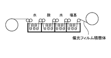
次に、図4に示すように、偏光フィルム積層体(実質的には、偏光子)を脱色処理に供する。偏光子の脱色により非偏光部が形成され得る。脱色処理は、偏光フィルム積層体を塩基性溶液と接触させることを含む。二色性物質としてヨウ素を用いる場合、偏光子の所望の部位に塩基性溶液を接触させることで、接触部のヨウ素含有量を容易に低減させることができる。以下、具体的に説明する。なお、塩基性溶液を脱色液と、酸性溶液を処理液と称する場合がある。 B. Production of polarizer with non-polarizing part (decolorization treatment of polarizing film laminate)
Next, as shown in FIG. 4, the polarizing film laminate (substantially a polarizer) is subjected to a decoloring process. A non-polarizing part may be formed by decoloring the polarizer. The decoloring treatment includes bringing the polarizing film laminate into contact with a basic solution. When iodine is used as the dichroic substance, the iodine content in the contact portion can be easily reduced by bringing a basic solution into contact with a desired portion of the polarizer. This will be specifically described below. In addition, a basic solution may be called a decoloring liquid and an acidic solution may be called a processing liquid.

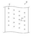
図5は、本発明の実施形態による製造方法により得られた非偏光部を有する長尺状偏光子の概略斜視図である。偏光子10は、長尺方向および/または幅方向に所定の間隔で(すなわち、所定のパターンで)配置された非偏光部11を有する。非偏光部11は、代表的には、偏光子を所定サイズの画像表示装置に取り付けるために所定サイズに裁断(例えば、長尺方向および/または幅方向への切断、打ち抜き)した際に、該画像表示装置のカメラ部に対応する位置に配置されている。非偏光部11の配置パターンは、上記の第1の表面保護フィルムの貫通孔の配置パターンに対応する。図示例における非偏光部の配置パターンは、図1および図2Aに示した貫通孔の配置パターンに対応する。すなわち、非偏光部11は、長尺方向および幅方向のいずれにおいても実質的に等間隔で配置されている。このような構成であれば、画像表示装置のサイズに合わせた偏光子の所定サイズへの裁断の制御が容易であり、歩留まりを向上させることができる。さらに、裁断された枚葉の偏光子片における非偏光部の位置のばらつきを抑制することができる。上記のとおり、非偏光部の配置パターンは、第1の表面保護フィルムの貫通孔の配置パターンを設定することにより容易に設定され得る。例えば、1つの長尺状偏光子から複数のサイズの偏光子片を裁断する場合には、長尺方向および/または幅方向における非偏光部11の間隔を裁断すべき偏光子のサイズに応じて変更することができる。また例えば、非偏光部の配置パターンは、図2Bに示した貫通孔の配置パターンに対応させてもよく、図2Cに示した貫通孔の配置パターンに対応させてもよい。図2Bおよび図2Cに示すような配置パターンは、以下のような利点を有する:画像表示装置によっては表示特性を向上させるために偏光子の吸収軸を当該装置の長辺または短辺に対して最大で10°程度ずらして配置することを要求される場合がある。後述するように偏光子の吸収軸は長尺方向または幅方向に発現するので、上記のような構成であれば、このような場合において、裁断された枚葉の偏光子の吸収軸の方向を所望の角度に精密に制御することができ、かつ、偏光子ごとの吸収軸の方向のばらつきを顕著に抑制することができる。 C. FIG. 5 is a schematic perspective view of a long polarizer having a non-polarizing part obtained by the manufacturing method according to the embodiment of the present invention. The
樹脂基材として、長尺状で、吸水率0.75%、Tg75℃の非晶質のイソフタル酸共重合ポリエチレンテレフタレート(IPA共重合PET)フィルム(厚み:100μm)を用いた。基材の片面に、コロナ処理を施し、このコロナ処理面に、ポリビニルアルコール(重合度4200、ケン化度99.2モル%)およびアセトアセチル変性PVA(重合度1200、アセトアセチル変性度4.6%、ケン化度99.0モル%以上、日本合成化学工業社製、商品名「ゴーセファイマーZ200」)を9:1の比で含む水溶液を25℃で塗布および乾燥して、厚み11μmのPVA系樹脂層を形成し、積層体を作製した。
得られた積層体を、120℃のオーブン内で周速の異なるロール間で縦方向(長手方向)に2.0倍に自由端一軸延伸した(空中補助延伸)。
次いで、積層体を、液温30℃の不溶化浴(水100重量部に対して、ホウ酸を4重量部配合して得られたホウ酸水溶液)に30秒間浸漬させた(不溶化処理)。
次いで、液温30℃の染色浴に、偏光板が所定の透過率となるようにヨウ素濃度、浸漬時間を調整しながら浸漬させた。本実施例では、水100重量部に対して、ヨウ素を0.2重量部配合し、ヨウ化カリウムを1.5重量部配合して得られたヨウ素水溶液に60秒間浸漬させた(染色処理)。
次いで、液温30℃の架橋浴(水100重量部に対して、ヨウ化カリウムを3重量部配合し、ホウ酸を3重量部配合して得られたホウ酸水溶液)に30秒間浸漬させた(架橋処理)。
その後、積層体を、液温70℃のホウ酸水溶液(水100重量部に対して、ホウ酸を4重量部配合し、ヨウ化カリウムを5重量部配合して得られた水溶液)に浸漬させながら、周速の異なるロール間で縦方向(長手方向)に総延伸倍率が5.5倍となるように一軸延伸を行った(水中延伸)。
その後、積層体を液温30℃の洗浄浴(水100重量部に対して、ヨウ化カリウムを4重量部配合して得られた水溶液)に浸漬させた(洗浄処理)。
続いて、積層体のPVA系樹脂層表面に、PVA系樹脂水溶液(日本合成化学工業社製、商品名「ゴーセファイマー(登録商標)Z-200」、樹脂濃度:3重量%)を塗布して保護フィルム(厚み25μm)を貼り合わせ、これを60℃に維持したオーブンで5分間加熱した。その後、基材をPVA系樹脂層から剥離し、幅1200mm、長さ43mの長尺状の偏光板(厚み5μmの偏光子(単体透過率42.3%)/保護フィルム)を得た。 [Example 1]
As the resin substrate, an amorphous isophthalic acid copolymerized polyethylene terephthalate (IPA copolymerized PET) film (thickness: 100 μm) having a long water absorption rate of 0.75% and Tg of 75 ° C. was used. One side of the substrate was subjected to corona treatment, and polyvinyl alcohol (degree of polymerization 4200, saponification degree 99.2 mol%) and acetoacetyl-modified PVA (degree of polymerization 1200, degree of acetoacetyl modification 4.6) were applied to this corona-treated surface. %, A saponification degree of 99.0 mol% or more, an aqueous solution containing 9: 1 ratio of Nippon Gosei Kagaku Kogyo Co., Ltd., trade name “Gosefimer Z200”) was applied and dried at 25 ° C. to a thickness of 11 μm. A PVA resin layer was formed to prepare a laminate.
The obtained laminate was uniaxially stretched in the longitudinal direction (longitudinal direction) 2.0 times between rolls having different peripheral speeds in an oven at 120 ° C. (air-assisted stretching).
Next, the laminate was immersed in an insolubilization bath (a boric acid aqueous solution obtained by blending 4 parts by weight of boric acid with respect to 100 parts by weight of water) for 30 seconds (insolubilization treatment).
Subsequently, it was immersed in a dyeing bath having a liquid temperature of 30 ° C. while adjusting the iodine concentration and the immersion time so that the polarizing plate had a predetermined transmittance. In this example, 0.2 parts by weight of iodine was blended with 100 parts by weight of water and immersed in an aqueous iodine solution obtained by blending 1.5 parts by weight of potassium iodide (dyeing treatment). .
Subsequently, it was immersed for 30 seconds in a crosslinking bath having a liquid temperature of 30 ° C. (a boric acid aqueous solution obtained by blending 3 parts by weight of potassium iodide and 3 parts by weight of boric acid with respect to 100 parts by weight of water). (Crosslinking treatment).
Thereafter, the laminate was immersed in a boric acid aqueous solution (an aqueous solution obtained by blending 4 parts by weight of boric acid and 5 parts by weight of potassium iodide with respect to 100 parts by weight of water) at a liquid temperature of 70 ° C. However, uniaxial stretching was performed in the longitudinal direction (longitudinal direction) between rolls having different peripheral speeds so that the total stretching ratio was 5.5 times (in-water stretching).
Thereafter, the laminate was immersed in a cleaning bath (an aqueous solution obtained by blending 4 parts by weight of potassium iodide with respect to 100 parts by weight of water) at a liquid temperature of 30 ° C. (cleaning treatment).
Subsequently, a PVA resin aqueous solution (manufactured by Nippon Synthetic Chemical Industry Co., Ltd., trade name “GOHSEPIMAR (registered trademark) Z-200”, resin concentration: 3% by weight) is applied to the surface of the PVA resin layer of the laminate. Then, a protective film (thickness 25 μm) was bonded, and this was heated in an oven maintained at 60 ° C. for 5 minutes. Thereafter, the substrate was peeled from the PVA resin layer to obtain a long polarizing plate having a width of 1200 mm and a length of 43 m (5 μm thick polarizer (single transmittance: 42.3%) / protective film).
厚み60μmのPVAフィルム(クラレ社製、PE6000)を、30℃の水溶液に30秒浸漬させた(膨潤工程)。
次いで、PVAフィルムを、液温30℃の染色浴に、得られる偏光板が所定の透過率となるようにヨウ素濃度、浸漬時間を調整しながら浸漬させた。本実施例では、水100重量部に対して、ヨウ素を0.15重量部配合し、ヨウ化カリウムを1.0重量部配合して得られたヨウ素水溶液に60秒間浸漬させた(染色処理)。
次いで、液温30℃の架橋浴(水100重量部に対して、ヨウ化カリウムを3重量部配合し、ホウ酸を3重量部配合して得られたホウ酸水溶液)に30秒間浸漬させた(架橋処理)。
その後、PVAフィルムを、液温70℃のホウ酸水溶液(水100重量部に対して、ホウ酸を4重量部配合し、ヨウ化カリウムを5重量部配合して得られた水溶液)に浸漬させながら、周速の異なるロール間で縦方向(長手方向)に5.5倍に一軸延伸を行った(水中延伸)。
その後、PVAフィルムを液温30℃の洗浄浴(水100重量部に対して、ヨウ化カリウムを4重量部配合して得られた水溶液)に浸漬させた(洗浄処理)。
洗浄後、PVAフィルムの片面に、PVA系樹脂水溶液(日本合成化学工業社製、商品名「ゴーセファイマー(登録商標)Z-200」、樹脂濃度:3重量%)を塗布し、トリアセチルセルロースフィルム(コニカミノルタ社製、商品名「KC4UY」、厚み40μm)を貼り合わせ、これを60℃に維持したオーブンで5分間加熱し、厚み22μmの偏光子(単体透過率42.5%)を有し、幅1200mm、長さ43mの偏光板を作製した。 [Example 2]
A PVA film having a thickness of 60 μm (PE6000, manufactured by Kuraray Co., Ltd.) was immersed in an aqueous solution at 30 ° C. for 30 seconds (swelling step).
Next, the PVA film was immersed in a dyeing bath having a liquid temperature of 30 ° C. while adjusting the iodine concentration and the immersion time so that the obtained polarizing plate had a predetermined transmittance. In this example, 0.15 parts by weight of iodine and 100 parts by weight of potassium iodide were mixed for 60 seconds with 100 parts by weight of water (dyeing treatment). .
Subsequently, it was immersed for 30 seconds in a crosslinking bath having a liquid temperature of 30 ° C. (a boric acid aqueous solution obtained by blending 3 parts by weight of potassium iodide and 3 parts by weight of boric acid with respect to 100 parts by weight of water). (Crosslinking treatment).
Thereafter, the PVA film is immersed in an aqueous boric acid solution having a liquid temperature of 70 ° C. (an aqueous solution obtained by blending 4 parts by weight of boric acid and 5 parts by weight of potassium iodide with respect to 100 parts by weight of water). However, uniaxial stretching was performed 5.5 times in the longitudinal direction (longitudinal direction) between rolls having different peripheral speeds (in-water stretching).
Thereafter, the PVA film was immersed in a cleaning bath (an aqueous solution obtained by adding 4 parts by weight of potassium iodide to 100 parts by weight of water) at a liquid temperature of 30 ° C. (cleaning treatment).
After washing, a PVA-based resin aqueous solution (manufactured by Nippon Gosei Kagaku Kogyo Co., Ltd., trade name “GOHSEIMER (registered trademark) Z-200”, resin concentration: 3% by weight) is applied to one side of the PVA film, and triacetylcellulose is applied. A film (made by Konica Minolta, trade name “KC4UY”,
1.透過率(Ts)
分光光度計(村上色彩技術研究所(株)製 製品名「DOT-3」)を用いて測定した。透過率(T)は、JlS Z 8701-1982の2度視野(C光源)により、視感度補正を行ったY値である。
2.ヨウ素含有量
蛍光X線分析により、偏光子の透明部におけるヨウ素含有量を求めた。具体的には、下記条件により測定したX線強度から、あらかじめ標準試料を用いて作成した検量線により、偏光子のヨウ素含有量を求めた。
・分析装置:理学電機工業製 蛍光X線分析装置(XRF) 製品名「ZSX100e」
・対陰極:ロジウム
・分光結晶:フッ化リチウム
・励起光エネルギー:40kV-90mA
・ヨウ素測定線:I-LA
・定量法:FP法
・2θ角ピーク:103.078deg(ヨウ素)
・測定時間:40秒 The following items were evaluated about the transparent part of the polarizing plate of each Example.
1. Transmittance (Ts)
The measurement was performed using a spectrophotometer (product name “DOT-3” manufactured by Murakami Color Research Laboratory Co., Ltd.). The transmittance (T) is a Y value obtained by correcting the visibility with a 2-degree field of view (C light source) of JlS Z 8701-1982.
2. Iodine content The iodine content in the transparent part of the polarizer was determined by fluorescent X-ray analysis. Specifically, the iodine content of the polarizer was determined from an X-ray intensity measured under the following conditions, using a calibration curve prepared in advance using a standard sample.
・ Analyzer: X-ray fluorescence analyzer (XRF) manufactured by Rigaku Denki Kogyo Co., Ltd. Product name “ZSX100e”
・ Anti-cathode: Rhodium ・ Spectral crystal: Lithium fluoride ・ Excitation light energy: 40 kV-90 mA
・ Iodine measurement line: I-LA
Quantitative method: FP method 2θ angle peak: 103.078 deg (iodine)
・ Measurement time: 40 seconds
蛍光X線分析により、偏光子の透明部におけるナトリウム含有量を求めた。具体的には、下記条件により測定したX線強度から、あらかじめ標準試料を用いて作成した検量線により、偏光子のナトリウム含有量を求めた。ナトリウム含有量の測定は、塩酸への浸漬前、および、浸漬後に行った。
・分析装置:理学電機工業製 蛍光X線分析装置(XRF) 製品名「ZSX100e」
・対陰極:ロジウム
・分光結晶:フッ化リチウム
・励起光エネルギー:40kV-90mA
・ナトリウム測定線:Na-KA
・定量法:FP法
・測定時間:40秒 3. Sodium content The sodium content in the transparent part of the polarizer was determined by fluorescent X-ray analysis. Specifically, the sodium content of the polarizer was determined from an X-ray intensity measured under the following conditions, using a calibration curve prepared in advance using a standard sample. The sodium content was measured before and after immersion in hydrochloric acid.
・ Analyzer: X-ray fluorescence analyzer (XRF) manufactured by Rigaku Denki Kogyo Co., Ltd. Product name “ZSX100e”
・ Anti-cathode: Rhodium ・ Spectral crystal: Lithium fluoride ・ Excitation light energy: 40 kV-90 mA
・ Sodium measurement line: Na-KA
・ Quantitative method: FP method ・ Measurement time: 40 seconds
11 非偏光部
20 保護フィルム
30 第2の表面保護フィルム
40 積層体
50 第1の表面保護フィルム
51 露出部
61 貫通孔
100 偏光フィルム積層体 DESCRIPTION OF
Claims (17)
- 長尺状の偏光子の一方の面に、長尺方向および/または幅方向に所定の間隔で配置された貫通孔を有する長尺状の表面保護フィルムを積層して、長尺状の偏光フィルム積層体を形成すること、
該表面保護フィルムの貫通孔を介して該偏光子を部分的に脱色して非偏光部を形成すること、および
該表面保護フィルムを除去すること
を含む、非偏光部を有する長尺状の偏光子の製造方法。 A long polarizing film is formed by laminating a long surface protective film having through holes arranged at predetermined intervals in the long direction and / or the width direction on one surface of a long polarizer. Forming a laminate,
Long-polarized light having a non-polarizing part, comprising: partially decoloring the polarizer through a through-hole of the surface protective film to form a non-polarizing part; and removing the surface protective film Child manufacturing method. - 前記貫通孔が、前記長尺方向に所定の間隔で配置されている、請求項1に記載の製造方法。 The manufacturing method according to claim 1, wherein the through holes are arranged at predetermined intervals in the longitudinal direction.
- 前記貫通孔が、少なくとも前記長尺方向に実質的に等間隔で配置されている、請求項1または2に記載の製造方法。 The manufacturing method according to claim 1 or 2, wherein the through holes are arranged at substantially equal intervals in at least the longitudinal direction.
- 前記貫通孔が、前記長尺方向および前記幅方向に実質的に等間隔で配置されている、請求項1から3のいずれかに記載の製造方法。 The manufacturing method according to any one of claims 1 to 3, wherein the through holes are arranged at substantially equal intervals in the longitudinal direction and the width direction.
- 前記貫通孔がドット状に配置されている、請求項1から4のいずれかに記載の製造方法。 The manufacturing method according to any one of claims 1 to 4, wherein the through holes are arranged in a dot shape.
- 前記貫通孔の平面視形状が、略円形状または略矩形状である、請求項1から5のいずれかに記載の製造方法。 The manufacturing method according to any one of claims 1 to 5, wherein a shape of the through hole in a plan view is a substantially circular shape or a substantially rectangular shape.
- 前記脱色が、前記偏光子を塩基性溶液に接触させることにより行われる、請求項1から6のいずれかに記載の製造方法。 The production method according to any one of claims 1 to 6, wherein the decolorization is performed by bringing the polarizer into contact with a basic solution.
- 前記長尺状の偏光子の他方の面に長尺状の保護フィルムが配置されている、請求項1から7のいずれかに記載の製造方法。 The manufacturing method according to any one of claims 1 to 7, wherein a long protective film is disposed on the other surface of the long polarizer.
- 前記脱色の前に前記長尺状の偏光子の他方の面の最外部に長尺状の第2の表面保護フィルムを積層すること、および、該脱色の後に該第2の表面保護フィルムを除去することをさらに含む、請求項1から8のいずれかに記載の製造方法。 Laminating a long second surface protective film on the outermost side of the other surface of the long polarizer before the decolorization, and removing the second surface protective film after the decolorization The manufacturing method according to claim 1, further comprising:
- 前記脱色が、前記偏光子を塩基性溶液に浸漬することにより行われる、請求項7から9のいずれかに記載の製造方法。 The method according to any one of claims 7 to 9, wherein the decolorization is performed by immersing the polarizer in a basic solution.
- 前記脱色により、前記偏光子の前記表面保護フィルム側に凹部を形成する、請求項1から10のいずれかに記載の製造方法。 The manufacturing method according to any one of claims 1 to 10, wherein a concave portion is formed on the surface protective film side of the polarizer by the decolorization.
- 前記脱色により形成される前記非偏光部が、他の部位よりも二色性物質の含有量が低い低濃度部である、請求項1から11のいずれかに記載の製造方法。 The manufacturing method according to any one of claims 1 to 11, wherein the non-polarizing part formed by the decolorization is a low-concentration part having a lower dichroic substance content than other parts.
- 前記二色性物質の低減が、前記低濃度部における二色性物質の含有量が0.2重量%以下となるようにして行われる、請求項12に記載の製造方法。 The method according to claim 12, wherein the reduction of the dichroic substance is performed such that the content of the dichroic substance in the low concentration portion is 0.2% by weight or less.
- 前記脱色の後、前記偏光子の前記塩基性溶液を接触させた接触部において、該偏光子に含まれるアルカリ金属および/またはアルカリ土類金属を低減させることをさらに含む、請求項7から13のいずれかに記載の製造方法。 14. The method according to claim 7, further comprising: reducing alkali metal and / or alkaline earth metal contained in the polarizer at the contact portion where the basic solution of the polarizer is contacted after the decolorization. The manufacturing method in any one.
- 前記アルカリ金属および/またはアルカリ土類金属の低減が、前記接触部におけるアルカリ金属および/またはアルカリ土類金属の含有量が3.6重量%以下となるようにして行われる、請求項14に記載の製造方法。 The reduction of the alkali metal and / or alkaline earth metal is performed so that the content of alkali metal and / or alkaline earth metal in the contact portion is 3.6% by weight or less. Manufacturing method.
- 前記偏光子の厚みが10μm以下である、請求項1から15のいずれかに記載の製造方法。 The manufacturing method according to claim 1, wherein the polarizer has a thickness of 10 μm or less.
- 前記保護フィルムの厚みが80μm以下である、請求項8から16のいずれかに記載の製造方法。
The manufacturing method in any one of Claim 8 to 16 whose thickness of the said protective film is 80 micrometers or less.
Priority Applications (3)
| Application Number | Priority Date | Filing Date | Title |
|---|---|---|---|
| KR1020157036688A KR101848987B1 (en) | 2014-06-27 | 2015-06-26 | Method of manufacturing long polarizer |
| CN201580035100.0A CN106471404B (en) | 2014-06-27 | 2015-06-26 | The manufacturing method of the polarisation part of strip |
| US15/321,974 US20170129197A1 (en) | 2014-06-27 | 2015-06-26 | Method for manufacturing long polarizer |
Applications Claiming Priority (4)
| Application Number | Priority Date | Filing Date | Title |
|---|---|---|---|
| JP2014-132608 | 2014-06-27 | ||
| JP2014132608 | 2014-06-27 | ||
| JP2015127644A JP6215262B2 (en) | 2014-06-27 | 2015-06-25 | Manufacturing method of long polarizer |
| JP2015-127644 | 2015-06-25 |
Publications (1)
| Publication Number | Publication Date |
|---|---|
| WO2015199217A1 true WO2015199217A1 (en) | 2015-12-30 |
Family
ID=54938294
Family Applications (1)
| Application Number | Title | Priority Date | Filing Date |
|---|---|---|---|
| PCT/JP2015/068504 WO2015199217A1 (en) | 2014-06-27 | 2015-06-26 | Method for manufacturing long polarizer |
Country Status (6)
| Country | Link |
|---|---|
| US (1) | US20170129197A1 (en) |
| JP (1) | JP6215262B2 (en) |
| KR (1) | KR101848987B1 (en) |
| CN (1) | CN106471404B (en) |
| TW (1) | TWI669542B (en) |
| WO (1) | WO2015199217A1 (en) |
Cited By (3)
| Publication number | Priority date | Publication date | Assignee | Title |
|---|---|---|---|---|
| KR20170083789A (en) * | 2016-01-11 | 2017-07-19 | 주식회사 엘지화학 | Polarizer, method for preparing the same and display device comprising the same |
| JP2017142293A (en) * | 2016-02-08 | 2017-08-17 | 日東電工株式会社 | Optical film and optical display panel |
| CN109478383A (en) * | 2016-07-22 | 2019-03-15 | 日东电工株式会社 | The manufacturing method of optical display panel and the manufacture system of optical display panel |
Families Citing this family (24)
| Publication number | Priority date | Publication date | Assignee | Title |
|---|---|---|---|---|
| JP6214594B2 (en) | 2014-04-25 | 2017-10-18 | 日東電工株式会社 | Polarizer, polarizing plate and image display device |
| JP6215864B2 (en) | 2014-04-25 | 2017-10-18 | 日東電工株式会社 | Polarizer, polarizing plate and image display device |
| JP6713189B2 (en) * | 2014-06-27 | 2020-06-24 | 日東電工株式会社 | Long polarizing film laminate |
| JP6215261B2 (en) | 2014-06-27 | 2017-10-18 | 日東電工株式会社 | Long polarizer, long polarizing plate and image display device |
| KR101766015B1 (en) * | 2014-06-30 | 2017-08-08 | 주식회사 엘지화학 | Method for manufacturing polarizing plate |
| JP7163000B2 (en) | 2015-06-25 | 2022-10-31 | 日東電工株式会社 | Polarizer with non-polarizing portion |
| JP6422415B2 (en) | 2015-09-28 | 2018-11-14 | 日東電工株式会社 | Polarizer, polarizing plate and image display device |
| JP6619619B2 (en) * | 2015-11-04 | 2019-12-11 | 日東電工株式会社 | Polarizer, polarizing plate, and method for producing polarizer |
| JP2018028563A (en) * | 2016-08-15 | 2018-02-22 | 日東電工株式会社 | Polarizing plate, method of manufacturing the same, and image display device having the same |
| JP2018031954A (en) * | 2016-08-26 | 2018-03-01 | 日東電工株式会社 | Polarizing plate and method for manufacturing the same, and image display device using polarizing plate |
| JP6945286B2 (en) * | 2016-09-13 | 2021-10-06 | 日東電工株式会社 | Polarizer manufacturing method |
| CN106772755B (en) * | 2017-02-27 | 2019-03-29 | 合肥京东方光电科技有限公司 | A kind of polaroid and liquid crystal display |
| JP6956268B2 (en) | 2018-07-11 | 2021-11-02 | 日産自動車株式会社 | Driving environment information generation method, driving control method, driving environment information generation device |
| KR102611927B1 (en) | 2018-07-11 | 2023-12-08 | 르노 에스.아.에스. | Driving environment information generation method, driving control method, driving environment information generating device |
| JP2020020973A (en) * | 2018-08-01 | 2020-02-06 | 日東電工株式会社 | Polarizer, polarizing plate, and image display device |
| JP7191578B2 (en) * | 2018-08-01 | 2022-12-19 | 日東電工株式会社 | Polarizer, polarizing plate, and image display device |
| JP2020024240A (en) * | 2018-08-06 | 2020-02-13 | 日東電工株式会社 | Method for manufacturing polarizer |
| KR102239441B1 (en) | 2018-08-22 | 2021-04-12 | 주식회사 엘지화학 | Method for preparing polarizing plate using mask film and polarizing plate same |
| JP7294909B2 (en) | 2018-10-15 | 2023-06-20 | 日東電工株式会社 | Polarizing plate with retardation layer and image display device using the same |
| JP7294908B2 (en) | 2018-10-15 | 2023-06-20 | 日東電工株式会社 | Polarizing plate with retardation layer and image display device using the same |
| JP6655205B1 (en) | 2018-12-13 | 2020-02-26 | 住友化学株式会社 | Punching tool and punching method |
| KR20210038756A (en) | 2019-09-30 | 2021-04-08 | 삼성디스플레이 주식회사 | Display device |
| CN113703086B (en) * | 2021-09-09 | 2022-07-26 | 武汉华星光电半导体显示技术有限公司 | Polarizer, manufacturing method thereof and display device |
| CN113777689B (en) * | 2021-09-24 | 2023-07-18 | 业成科技(成都)有限公司 | Depolarization method, polarizing plate and display device |
Citations (5)
| Publication number | Priority date | Publication date | Assignee | Title |
|---|---|---|---|---|
| JPS58168019A (en) * | 1982-03-29 | 1983-10-04 | Nitto Electric Ind Co Ltd | Manufacture of partially colored polarizing film |
| US5327285A (en) * | 1990-06-11 | 1994-07-05 | Faris Sadeg M | Methods for manufacturing micropolarizers |
| WO2009128122A1 (en) * | 2008-04-15 | 2009-10-22 | 日東電工株式会社 | Laminate roll of optical film and process and apparatus for producing the same |
| JP2012137738A (en) * | 2010-10-29 | 2012-07-19 | Apple Inc | Displays with polarizer windows and opaque masking layers for electronic devices |
| JP2014081482A (en) * | 2012-10-16 | 2014-05-08 | Nitto Denko Corp | Polarizer and image display device |
Family Cites Families (4)
| Publication number | Priority date | Publication date | Assignee | Title |
|---|---|---|---|---|
| US4396646A (en) * | 1981-07-20 | 1983-08-02 | Polaroid Corporation | Method of making patterned polarizers |
| JPH10183390A (en) * | 1996-12-25 | 1998-07-14 | Nikko Kinzoku Kk | Pattern plating method for long-sized metallic strip |
| JP2003207608A (en) * | 2001-11-12 | 2003-07-25 | Sony Corp | Nd filter and its manufacturing method, and imaging device |
| CN105229505B (en) * | 2014-03-26 | 2018-01-16 | Lg化学株式会社 | The method of polaroid of the manufacture with the local region that depolarizes, and polaroid, Polarizer and the image display device manufactured by using this method |
-
2015
- 2015-06-25 JP JP2015127644A patent/JP6215262B2/en active Active
- 2015-06-26 US US15/321,974 patent/US20170129197A1/en not_active Abandoned
- 2015-06-26 TW TW104120914A patent/TWI669542B/en active
- 2015-06-26 WO PCT/JP2015/068504 patent/WO2015199217A1/en active Application Filing
- 2015-06-26 CN CN201580035100.0A patent/CN106471404B/en active Active
- 2015-06-26 KR KR1020157036688A patent/KR101848987B1/en active IP Right Grant
Patent Citations (5)
| Publication number | Priority date | Publication date | Assignee | Title |
|---|---|---|---|---|
| JPS58168019A (en) * | 1982-03-29 | 1983-10-04 | Nitto Electric Ind Co Ltd | Manufacture of partially colored polarizing film |
| US5327285A (en) * | 1990-06-11 | 1994-07-05 | Faris Sadeg M | Methods for manufacturing micropolarizers |
| WO2009128122A1 (en) * | 2008-04-15 | 2009-10-22 | 日東電工株式会社 | Laminate roll of optical film and process and apparatus for producing the same |
| JP2012137738A (en) * | 2010-10-29 | 2012-07-19 | Apple Inc | Displays with polarizer windows and opaque masking layers for electronic devices |
| JP2014081482A (en) * | 2012-10-16 | 2014-05-08 | Nitto Denko Corp | Polarizer and image display device |
Cited By (5)
| Publication number | Priority date | Publication date | Assignee | Title |
|---|---|---|---|---|
| KR20170083789A (en) * | 2016-01-11 | 2017-07-19 | 주식회사 엘지화학 | Polarizer, method for preparing the same and display device comprising the same |
| KR102097816B1 (en) * | 2016-01-11 | 2020-04-07 | 주식회사 엘지화학 | Polarizer, method for preparing the same and display device comprising the same |
| JP2017142293A (en) * | 2016-02-08 | 2017-08-17 | 日東電工株式会社 | Optical film and optical display panel |
| JP7334024B2 (en) | 2016-02-08 | 2023-08-28 | 日東電工株式会社 | Optical film and optical display panel |
| CN109478383A (en) * | 2016-07-22 | 2019-03-15 | 日东电工株式会社 | The manufacturing method of optical display panel and the manufacture system of optical display panel |
Also Published As
| Publication number | Publication date |
|---|---|
| CN106471404B (en) | 2019-11-19 |
| KR20160016904A (en) | 2016-02-15 |
| JP6215262B2 (en) | 2017-10-18 |
| KR101848987B1 (en) | 2018-04-13 |
| TWI669542B (en) | 2019-08-21 |
| CN106471404A (en) | 2017-03-01 |
| JP2016027394A (en) | 2016-02-18 |
| US20170129197A1 (en) | 2017-05-11 |
| TW201606361A (en) | 2016-02-16 |
Similar Documents
| Publication | Publication Date | Title |
|---|---|---|
| JP6215262B2 (en) | Manufacturing method of long polarizer | |
| JP6215261B2 (en) | Long polarizer, long polarizing plate and image display device | |
| WO2016208535A1 (en) | Polarizer | |
| JP6713189B2 (en) | Long polarizing film laminate | |
| WO2016132960A1 (en) | Method for manufacturing polarizer | |
| JP7369237B2 (en) | Manufacturing method of polarizing plate |
Legal Events
| Date | Code | Title | Description |
|---|---|---|---|
| ENP | Entry into the national phase |
Ref document number: 20157036688 Country of ref document: KR Kind code of ref document: A |
|
| 121 | Ep: the epo has been informed by wipo that ep was designated in this application |
Ref document number: 15811537 Country of ref document: EP Kind code of ref document: A1 |
|
| WWE | Wipo information: entry into national phase |
Ref document number: 15321974 Country of ref document: US |
|
| NENP | Non-entry into the national phase |
Ref country code: DE |
|
| 122 | Ep: pct application non-entry in european phase |
Ref document number: 15811537 Country of ref document: EP Kind code of ref document: A1 |