JP7294908B2 - Polarizing plate with retardation layer and image display device using the same - Google Patents
Polarizing plate with retardation layer and image display device using the same Download PDFInfo
- Publication number
- JP7294908B2 JP7294908B2 JP2019115122A JP2019115122A JP7294908B2 JP 7294908 B2 JP7294908 B2 JP 7294908B2 JP 2019115122 A JP2019115122 A JP 2019115122A JP 2019115122 A JP2019115122 A JP 2019115122A JP 7294908 B2 JP7294908 B2 JP 7294908B2
- Authority
- JP
- Japan
- Prior art keywords
- layer
- retardation layer
- polarizing plate
- retardation
- liquid crystal
- Prior art date
- Legal status (The legal status is an assumption and is not a legal conclusion. Google has not performed a legal analysis and makes no representation as to the accuracy of the status listed.)
- Active
Links
- 239000010410 layer Substances 0.000 claims description 319
- 229920005989 resin Polymers 0.000 claims description 144
- 239000011347 resin Substances 0.000 claims description 144
- 229920002451 polyvinyl alcohol Polymers 0.000 claims description 130
- 239000004372 Polyvinyl alcohol Substances 0.000 claims description 129
- 238000011282 treatment Methods 0.000 claims description 98
- 239000004973 liquid crystal related substance Substances 0.000 claims description 82
- 239000000758 substrate Substances 0.000 claims description 82
- 229920005992 thermoplastic resin Polymers 0.000 claims description 63
- 150000001875 compounds Chemical class 0.000 claims description 53
- 238000000034 method Methods 0.000 claims description 51
- 238000002834 transmittance Methods 0.000 claims description 51
- 238000010438 heat treatment Methods 0.000 claims description 45
- 239000011241 protective layer Substances 0.000 claims description 45
- 238000004043 dyeing Methods 0.000 claims description 39
- 238000001035 drying Methods 0.000 claims description 31
- 238000010521 absorption reaction Methods 0.000 claims description 25
- 230000010287 polarization Effects 0.000 claims description 25
- 238000004519 manufacturing process Methods 0.000 claims description 23
- XMBWDFGMSWQBCA-UHFFFAOYSA-N hydrogen iodide Chemical compound I XMBWDFGMSWQBCA-UHFFFAOYSA-N 0.000 claims description 11
- 239000002356 single layer Substances 0.000 claims description 8
- 239000000126 substance Substances 0.000 claims description 7
- FAPWRFPIFSIZLT-UHFFFAOYSA-M Sodium chloride Chemical compound [Na+].[Cl-] FAPWRFPIFSIZLT-UHFFFAOYSA-M 0.000 claims description 4
- 239000011780 sodium chloride Substances 0.000 claims description 2
- 235000019422 polyvinyl alcohol Nutrition 0.000 description 127
- XLYOFNOQVPJJNP-UHFFFAOYSA-N water Substances O XLYOFNOQVPJJNP-UHFFFAOYSA-N 0.000 description 55
- KGBXLFKZBHKPEV-UHFFFAOYSA-N boric acid Chemical compound OB(O)O KGBXLFKZBHKPEV-UHFFFAOYSA-N 0.000 description 43
- 239000004327 boric acid Substances 0.000 description 43
- 230000003287 optical effect Effects 0.000 description 43
- NLKNQRATVPKPDG-UHFFFAOYSA-M potassium iodide Chemical compound [K+].[I-] NLKNQRATVPKPDG-UHFFFAOYSA-M 0.000 description 42
- 239000000463 material Substances 0.000 description 36
- 239000007788 liquid Substances 0.000 description 31
- 239000007864 aqueous solution Substances 0.000 description 25
- 239000011248 coating agent Substances 0.000 description 25
- 238000000576 coating method Methods 0.000 description 25
- 239000000243 solution Substances 0.000 description 21
- 238000005259 measurement Methods 0.000 description 20
- 239000000178 monomer Substances 0.000 description 20
- 150000004820 halides Chemical class 0.000 description 18
- 230000008569 process Effects 0.000 description 18
- 238000002425 crystallisation Methods 0.000 description 15
- 230000008025 crystallization Effects 0.000 description 15
- 238000004132 cross linking Methods 0.000 description 14
- 238000005401 electroluminescence Methods 0.000 description 14
- 238000006116 polymerization reaction Methods 0.000 description 13
- 239000012790 adhesive layer Substances 0.000 description 12
- 230000000052 comparative effect Effects 0.000 description 12
- ZCYVEMRRCGMTRW-UHFFFAOYSA-N 7553-56-2 Chemical compound [I] ZCYVEMRRCGMTRW-UHFFFAOYSA-N 0.000 description 10
- 230000009477 glass transition Effects 0.000 description 10
- 229910052740 iodine Inorganic materials 0.000 description 10
- 239000011630 iodine Substances 0.000 description 10
- -1 polyethylene terephthalate Polymers 0.000 description 10
- 230000001681 protective effect Effects 0.000 description 10
- 239000000853 adhesive Substances 0.000 description 9
- 230000001070 adhesive effect Effects 0.000 description 9
- 229920000139 polyethylene terephthalate Polymers 0.000 description 9
- 239000005020 polyethylene terephthalate Substances 0.000 description 9
- 229920002284 Cellulose triacetate Polymers 0.000 description 8
- 239000004985 Discotic Liquid Crystal Substance Substances 0.000 description 8
- DKNPRRRKHAEUMW-UHFFFAOYSA-N Iodine aqueous Chemical compound [K+].I[I-]I DKNPRRRKHAEUMW-UHFFFAOYSA-N 0.000 description 8
- NNLVGZFZQQXQNW-ADJNRHBOSA-N [(2r,3r,4s,5r,6s)-4,5-diacetyloxy-3-[(2s,3r,4s,5r,6r)-3,4,5-triacetyloxy-6-(acetyloxymethyl)oxan-2-yl]oxy-6-[(2r,3r,4s,5r,6s)-4,5,6-triacetyloxy-2-(acetyloxymethyl)oxan-3-yl]oxyoxan-2-yl]methyl acetate Chemical compound O([C@@H]1O[C@@H]([C@H]([C@H](OC(C)=O)[C@H]1OC(C)=O)O[C@H]1[C@@H]([C@@H](OC(C)=O)[C@H](OC(C)=O)[C@@H](COC(C)=O)O1)OC(C)=O)COC(=O)C)[C@@H]1[C@@H](COC(C)=O)O[C@@H](OC(C)=O)[C@H](OC(C)=O)[C@H]1OC(C)=O NNLVGZFZQQXQNW-ADJNRHBOSA-N 0.000 description 8
- 238000012937 correction Methods 0.000 description 8
- 230000006866 deterioration Effects 0.000 description 8
- 238000011156 evaluation Methods 0.000 description 8
- 238000005452 bending Methods 0.000 description 7
- 238000002360 preparation method Methods 0.000 description 7
- 238000007127 saponification reaction Methods 0.000 description 7
- NIXOWILDQLNWCW-UHFFFAOYSA-N acrylic acid group Chemical group C(C=C)(=O)O NIXOWILDQLNWCW-UHFFFAOYSA-N 0.000 description 6
- 230000008859 change Effects 0.000 description 6
- 239000000470 constituent Substances 0.000 description 6
- QQVIHTHCMHWDBS-UHFFFAOYSA-N isophthalic acid Chemical compound OC(=O)C1=CC=CC(C(O)=O)=C1 QQVIHTHCMHWDBS-UHFFFAOYSA-N 0.000 description 6
- 238000002156 mixing Methods 0.000 description 6
- 239000000047 product Substances 0.000 description 6
- FVAUCKIRQBBSSJ-UHFFFAOYSA-M sodium iodide Chemical compound [Na+].[I-] FVAUCKIRQBBSSJ-UHFFFAOYSA-M 0.000 description 6
- 210000004027 cell Anatomy 0.000 description 5
- 239000002131 composite material Substances 0.000 description 5
- 230000007423 decrease Effects 0.000 description 5
- 239000006185 dispersion Substances 0.000 description 5
- 238000004090 dissolution Methods 0.000 description 5
- 238000007654 immersion Methods 0.000 description 5
- IJGRMHOSHXDMSA-UHFFFAOYSA-N nitrogen Substances N#N IJGRMHOSHXDMSA-UHFFFAOYSA-N 0.000 description 5
- 230000002093 peripheral effect Effects 0.000 description 5
- 239000002904 solvent Substances 0.000 description 5
- 238000012360 testing method Methods 0.000 description 5
- 238000005406 washing Methods 0.000 description 5
- LYCAIKOWRPUZTN-UHFFFAOYSA-N Ethylene glycol Chemical group OCCO LYCAIKOWRPUZTN-UHFFFAOYSA-N 0.000 description 4
- 239000004820 Pressure-sensitive adhesive Substances 0.000 description 4
- 239000011521 glass Substances 0.000 description 4
- 150000004694 iodide salts Chemical class 0.000 description 4
- HSZCZNFXUDYRKD-UHFFFAOYSA-M lithium iodide Chemical compound [Li+].[I-] HSZCZNFXUDYRKD-UHFFFAOYSA-M 0.000 description 4
- 229920000728 polyester Polymers 0.000 description 4
- 238000000870 ultraviolet spectroscopy Methods 0.000 description 4
- UHOVQNZJYSORNB-UHFFFAOYSA-N Benzene Chemical compound C1=CC=CC=C1 UHOVQNZJYSORNB-UHFFFAOYSA-N 0.000 description 3
- BVKZGUZCCUSVTD-UHFFFAOYSA-L Carbonate Chemical compound [O-]C([O-])=O BVKZGUZCCUSVTD-UHFFFAOYSA-L 0.000 description 3
- 229920000106 Liquid crystal polymer Polymers 0.000 description 3
- 239000004977 Liquid-crystal polymers (LCPs) Substances 0.000 description 3
- ZMXDDKWLCZADIW-UHFFFAOYSA-N N,N-Dimethylformamide Chemical compound CN(C)C=O ZMXDDKWLCZADIW-UHFFFAOYSA-N 0.000 description 3
- 239000004988 Nematic liquid crystal Substances 0.000 description 3
- ISWSIDIOOBJBQZ-UHFFFAOYSA-N Phenol Chemical compound OC1=CC=CC=C1 ISWSIDIOOBJBQZ-UHFFFAOYSA-N 0.000 description 3
- YXFVVABEGXRONW-UHFFFAOYSA-N Toluene Chemical compound CC1=CC=CC=C1 YXFVVABEGXRONW-UHFFFAOYSA-N 0.000 description 3
- 230000005540 biological transmission Effects 0.000 description 3
- 230000015572 biosynthetic process Effects 0.000 description 3
- MTHSVFCYNBDYFN-UHFFFAOYSA-N diethylene glycol Chemical compound OCCOCCO MTHSVFCYNBDYFN-UHFFFAOYSA-N 0.000 description 3
- 230000000694 effects Effects 0.000 description 3
- 238000007602 hot air drying Methods 0.000 description 3
- 229910044991 metal oxide Inorganic materials 0.000 description 3
- 150000004706 metal oxides Chemical class 0.000 description 3
- 229910052757 nitrogen Inorganic materials 0.000 description 3
- JFNLZVQOOSMTJK-KNVOCYPGSA-N norbornene Chemical compound C1[C@@H]2CC[C@H]1C=C2 JFNLZVQOOSMTJK-KNVOCYPGSA-N 0.000 description 3
- 238000000059 patterning Methods 0.000 description 3
- 239000004014 plasticizer Substances 0.000 description 3
- 229920000642 polymer Polymers 0.000 description 3
- 239000011342 resin composition Substances 0.000 description 3
- 238000003756 stirring Methods 0.000 description 3
- 238000004381 surface treatment Methods 0.000 description 3
- 230000008961 swelling Effects 0.000 description 3
- 238000012546 transfer Methods 0.000 description 3
- 229920008790 Amorphous Polyethylene terephthalate Polymers 0.000 description 2
- 229920002799 BoPET Polymers 0.000 description 2
- IAZDPXIOMUYVGZ-UHFFFAOYSA-N Dimethylsulphoxide Chemical compound CS(C)=O IAZDPXIOMUYVGZ-UHFFFAOYSA-N 0.000 description 2
- JOYRKODLDBILNP-UHFFFAOYSA-N Ethyl urethane Chemical compound CCOC(N)=O JOYRKODLDBILNP-UHFFFAOYSA-N 0.000 description 2
- 229920000219 Ethylene vinyl alcohol Polymers 0.000 description 2
- UEXCJVNBTNXOEH-UHFFFAOYSA-N Ethynylbenzene Chemical group C#CC1=CC=CC=C1 UEXCJVNBTNXOEH-UHFFFAOYSA-N 0.000 description 2
- 206010052128 Glare Diseases 0.000 description 2
- PEDCQBHIVMGVHV-UHFFFAOYSA-N Glycerine Chemical compound OCC(O)CO PEDCQBHIVMGVHV-UHFFFAOYSA-N 0.000 description 2
- VQTUBCCKSQIDNK-UHFFFAOYSA-N Isobutene Chemical compound CC(C)=C VQTUBCCKSQIDNK-UHFFFAOYSA-N 0.000 description 2
- KLDXJTOLSGUMSJ-JGWLITMVSA-N Isosorbide Chemical compound O[C@@H]1CO[C@@H]2[C@@H](O)CO[C@@H]21 KLDXJTOLSGUMSJ-JGWLITMVSA-N 0.000 description 2
- 241000209094 Oryza Species 0.000 description 2
- 235000007164 Oryza sativa Nutrition 0.000 description 2
- XLOMVQKBTHCTTD-UHFFFAOYSA-N Zinc monoxide Chemical compound [Zn]=O XLOMVQKBTHCTTD-UHFFFAOYSA-N 0.000 description 2
- 239000000654 additive Substances 0.000 description 2
- 150000001642 boronic acid derivatives Chemical class 0.000 description 2
- 229920001577 copolymer Polymers 0.000 description 2
- 238000003851 corona treatment Methods 0.000 description 2
- 125000004122 cyclic group Chemical group 0.000 description 2
- 150000001925 cycloalkenes Chemical class 0.000 description 2
- 238000010586 diagram Methods 0.000 description 2
- ROORDVPLFPIABK-UHFFFAOYSA-N diphenyl carbonate Chemical compound C=1C=CC=CC=1OC(=O)OC1=CC=CC=C1 ROORDVPLFPIABK-UHFFFAOYSA-N 0.000 description 2
- 238000009826 distribution Methods 0.000 description 2
- 238000010828 elution Methods 0.000 description 2
- 150000002334 glycols Chemical class 0.000 description 2
- LEQAOMBKQFMDFZ-UHFFFAOYSA-N glyoxal Chemical compound O=CC=O LEQAOMBKQFMDFZ-UHFFFAOYSA-N 0.000 description 2
- RHZWSUVWRRXEJF-UHFFFAOYSA-N indium tin Chemical compound [In].[Sn] RHZWSUVWRRXEJF-UHFFFAOYSA-N 0.000 description 2
- 229960002479 isosorbide Drugs 0.000 description 2
- 239000008188 pellet Substances 0.000 description 2
- 229920006254 polymer film Polymers 0.000 description 2
- 230000000379 polymerizing effect Effects 0.000 description 2
- 238000012545 processing Methods 0.000 description 2
- 238000010992 reflux Methods 0.000 description 2
- 235000009566 rice Nutrition 0.000 description 2
- 235000009518 sodium iodide Nutrition 0.000 description 2
- 238000005507 spraying Methods 0.000 description 2
- 239000012192 staining solution Substances 0.000 description 2
- 150000005846 sugar alcohols Polymers 0.000 description 2
- 239000004094 surface-active agent Substances 0.000 description 2
- UAYWVJHJZHQCIE-UHFFFAOYSA-L zinc iodide Chemical compound I[Zn]I UAYWVJHJZHQCIE-UHFFFAOYSA-L 0.000 description 2
- JIHQDMXYYFUGFV-UHFFFAOYSA-N 1,3,5-triazine Chemical compound C1=NC=NC=N1 JIHQDMXYYFUGFV-UHFFFAOYSA-N 0.000 description 1
- LWRBVKNFOYUCNP-UHFFFAOYSA-N 2-methyl-1-(4-methylsulfanylphenyl)-2-morpholin-4-ylpropan-1-one Chemical compound C1=CC(SC)=CC=C1C(=O)C(C)(C)N1CCOCC1 LWRBVKNFOYUCNP-UHFFFAOYSA-N 0.000 description 1
- QTBSBXVTEAMEQO-UHFFFAOYSA-M Acetate Chemical compound CC([O-])=O QTBSBXVTEAMEQO-UHFFFAOYSA-M 0.000 description 1
- 239000004925 Acrylic resin Substances 0.000 description 1
- 229920000178 Acrylic resin Polymers 0.000 description 1
- UNMYWSMUMWPJLR-UHFFFAOYSA-L Calcium iodide Chemical compound [Ca+2].[I-].[I-] UNMYWSMUMWPJLR-UHFFFAOYSA-L 0.000 description 1
- RPNUMPOLZDHAAY-UHFFFAOYSA-N Diethylenetriamine Chemical compound NCCNCCN RPNUMPOLZDHAAY-UHFFFAOYSA-N 0.000 description 1
- 239000004593 Epoxy Substances 0.000 description 1
- LFQSCWFLJHTTHZ-UHFFFAOYSA-N Ethanol Chemical compound CCO LFQSCWFLJHTTHZ-UHFFFAOYSA-N 0.000 description 1
- PIICEJLVQHRZGT-UHFFFAOYSA-N Ethylenediamine Chemical compound NCCN PIICEJLVQHRZGT-UHFFFAOYSA-N 0.000 description 1
- 238000005033 Fourier transform infrared spectroscopy Methods 0.000 description 1
- SXRSQZLOMIGNAQ-UHFFFAOYSA-N Glutaraldehyde Chemical compound O=CCCCC=O SXRSQZLOMIGNAQ-UHFFFAOYSA-N 0.000 description 1
- FXHOOIRPVKKKFG-UHFFFAOYSA-N N,N-Dimethylacetamide Chemical compound CN(C)C(C)=O FXHOOIRPVKKKFG-UHFFFAOYSA-N 0.000 description 1
- SECXISVLQFMRJM-UHFFFAOYSA-N N-Methylpyrrolidone Chemical compound CN1CCCC1=O SECXISVLQFMRJM-UHFFFAOYSA-N 0.000 description 1
- 239000004952 Polyamide Substances 0.000 description 1
- 239000004642 Polyimide Substances 0.000 description 1
- 239000004743 Polypropylene Substances 0.000 description 1
- 239000004793 Polystyrene Substances 0.000 description 1
- ZJCCRDAZUWHFQH-UHFFFAOYSA-N Trimethylolpropane Chemical compound CCC(CO)(CO)CO ZJCCRDAZUWHFQH-UHFFFAOYSA-N 0.000 description 1
- 229910000611 Zinc aluminium Inorganic materials 0.000 description 1
- MBHRHUJRKGNOKX-UHFFFAOYSA-N [(4,6-diamino-1,3,5-triazin-2-yl)amino]methanol Chemical compound NC1=NC(N)=NC(NCO)=N1 MBHRHUJRKGNOKX-UHFFFAOYSA-N 0.000 description 1
- ORLQHILJRHBSAY-UHFFFAOYSA-N [1-(hydroxymethyl)cyclohexyl]methanol Chemical compound OCC1(CO)CCCCC1 ORLQHILJRHBSAY-UHFFFAOYSA-N 0.000 description 1
- 125000002339 acetoacetyl group Chemical group O=C([*])C([H])([H])C(=O)C([H])([H])[H] 0.000 description 1
- 229920001893 acrylonitrile styrene Polymers 0.000 description 1
- 150000001336 alkenes Chemical class 0.000 description 1
- 125000003545 alkoxy group Chemical group 0.000 description 1
- 125000000217 alkyl group Chemical group 0.000 description 1
- 229920005603 alternating copolymer Polymers 0.000 description 1
- HXFVOUUOTHJFPX-UHFFFAOYSA-N alumane;zinc Chemical compound [AlH3].[Zn] HXFVOUUOTHJFPX-UHFFFAOYSA-N 0.000 description 1
- CECABOMBVQNBEC-UHFFFAOYSA-K aluminium iodide Chemical compound I[Al](I)I CECABOMBVQNBEC-UHFFFAOYSA-K 0.000 description 1
- 150000001412 amines Chemical class 0.000 description 1
- GVFOJDIFWSDNOY-UHFFFAOYSA-N antimony tin Chemical compound [Sn].[Sb] GVFOJDIFWSDNOY-UHFFFAOYSA-N 0.000 description 1
- SGUXGJPBTNFBAD-UHFFFAOYSA-L barium iodide Chemical compound [I-].[I-].[Ba+2] SGUXGJPBTNFBAD-UHFFFAOYSA-L 0.000 description 1
- 229910001638 barium iodide Inorganic materials 0.000 description 1
- 229940075444 barium iodide Drugs 0.000 description 1
- 150000001555 benzenes Chemical class 0.000 description 1
- 125000003236 benzoyl group Chemical group [H]C1=C([H])C([H])=C(C([H])=C1[H])C(*)=O 0.000 description 1
- 238000007664 blowing Methods 0.000 description 1
- 229910021538 borax Inorganic materials 0.000 description 1
- 150000001639 boron compounds Chemical class 0.000 description 1
- 239000006227 byproduct Substances 0.000 description 1
- XQKKWWCELHKGKB-UHFFFAOYSA-L calcium acetate monohydrate Chemical compound O.[Ca+2].CC([O-])=O.CC([O-])=O XQKKWWCELHKGKB-UHFFFAOYSA-L 0.000 description 1
- 229940067460 calcium acetate monohydrate Drugs 0.000 description 1
- 229910001640 calcium iodide Inorganic materials 0.000 description 1
- 229940046413 calcium iodide Drugs 0.000 description 1
- VTJUKNSKBAOEHE-UHFFFAOYSA-N calixarene Chemical compound COC(=O)COC1=C(CC=2C(=C(CC=3C(=C(C4)C=C(C=3)C(C)(C)C)OCC(=O)OC)C=C(C=2)C(C)(C)C)OCC(=O)OC)C=C(C(C)(C)C)C=C1CC1=C(OCC(=O)OC)C4=CC(C(C)(C)C)=C1 VTJUKNSKBAOEHE-UHFFFAOYSA-N 0.000 description 1
- 239000003054 catalyst Substances 0.000 description 1
- 239000012461 cellulose resin Substances 0.000 description 1
- 238000006243 chemical reaction Methods 0.000 description 1
- 239000012295 chemical reaction liquid Substances 0.000 description 1
- 238000004140 cleaning Methods 0.000 description 1
- 229920006026 co-polymeric resin Polymers 0.000 description 1
- 230000008602 contraction Effects 0.000 description 1
- 238000001816 cooling Methods 0.000 description 1
- GBRBMTNGQBKBQE-UHFFFAOYSA-L copper;diiodide Chemical compound I[Cu]I GBRBMTNGQBKBQE-UHFFFAOYSA-L 0.000 description 1
- 239000013078 crystal Substances 0.000 description 1
- 210000002858 crystal cell Anatomy 0.000 description 1
- 238000007766 curtain coating Methods 0.000 description 1
- QYQADNCHXSEGJT-UHFFFAOYSA-N cyclohexane-1,1-dicarboxylate;hydron Chemical compound OC(=O)C1(C(O)=O)CCCCC1 QYQADNCHXSEGJT-UHFFFAOYSA-N 0.000 description 1
- 150000001934 cyclohexanes Chemical class 0.000 description 1
- 238000000151 deposition Methods 0.000 description 1
- 230000001687 destabilization Effects 0.000 description 1
- 238000011161 development Methods 0.000 description 1
- 150000001991 dicarboxylic acids Chemical class 0.000 description 1
- 238000007607 die coating method Methods 0.000 description 1
- 238000009792 diffusion process Methods 0.000 description 1
- 238000003618 dip coating Methods 0.000 description 1
- KPUWHANPEXNPJT-UHFFFAOYSA-N disiloxane Chemical class [SiH3]O[SiH3] KPUWHANPEXNPJT-UHFFFAOYSA-N 0.000 description 1
- 230000005684 electric field Effects 0.000 description 1
- 150000002148 esters Chemical class 0.000 description 1
- 239000005038 ethylene vinyl acetate Substances 0.000 description 1
- 230000001747 exhibiting effect Effects 0.000 description 1
- 239000004744 fabric Substances 0.000 description 1
- 238000001879 gelation Methods 0.000 description 1
- 235000011187 glycerol Nutrition 0.000 description 1
- 229940015043 glyoxal Drugs 0.000 description 1
- 239000001257 hydrogen Substances 0.000 description 1
- 229910052739 hydrogen Inorganic materials 0.000 description 1
- 125000005462 imide group Chemical group 0.000 description 1
- 229910003437 indium oxide Inorganic materials 0.000 description 1
- NJWNEWQMQCGRDO-UHFFFAOYSA-N indium zinc Chemical compound [Zn].[In] NJWNEWQMQCGRDO-UHFFFAOYSA-N 0.000 description 1
- PJXISJQVUVHSOJ-UHFFFAOYSA-N indium(iii) oxide Chemical compound [O-2].[O-2].[O-2].[In+3].[In+3] PJXISJQVUVHSOJ-UHFFFAOYSA-N 0.000 description 1
- 239000003999 initiator Substances 0.000 description 1
- PNDPGZBMCMUPRI-UHFFFAOYSA-N iodine Chemical compound II PNDPGZBMCMUPRI-UHFFFAOYSA-N 0.000 description 1
- 125000000686 lactone group Chemical group 0.000 description 1
- 238000003475 lamination Methods 0.000 description 1
- 230000002535 lyotropic effect Effects 0.000 description 1
- 150000002678 macrocyclic compounds Chemical class 0.000 description 1
- 238000000691 measurement method Methods 0.000 description 1
- 230000007246 mechanism Effects 0.000 description 1
- 229910052751 metal Inorganic materials 0.000 description 1
- 239000002184 metal Substances 0.000 description 1
- 229910001507 metal halide Inorganic materials 0.000 description 1
- 150000005309 metal halides Chemical class 0.000 description 1
- 239000000203 mixture Substances 0.000 description 1
- SEEYREPSKCQBBF-UHFFFAOYSA-N n-methylmaleimide Chemical compound CN1C(=O)C=CC1=O SEEYREPSKCQBBF-UHFFFAOYSA-N 0.000 description 1
- 125000002560 nitrile group Chemical group 0.000 description 1
- QJGQUHMNIGDVPM-UHFFFAOYSA-N nitrogen group Chemical group [N] QJGQUHMNIGDVPM-UHFFFAOYSA-N 0.000 description 1
- 239000002736 nonionic surfactant Substances 0.000 description 1
- JRZJOMJEPLMPRA-UHFFFAOYSA-N olefin Natural products CCCCCCCC=C JRZJOMJEPLMPRA-UHFFFAOYSA-N 0.000 description 1
- 125000001820 oxy group Chemical group [*:1]O[*:2] 0.000 description 1
- GROIHDHFSBIQKH-UHFFFAOYSA-N phenyl 3-[9-[[9-(3-oxo-3-phenoxypropyl)fluoren-9-yl]methyl]fluoren-9-yl]propanoate Chemical compound C=1C=CC=CC=1OC(=O)CCC1(C2=CC=CC=C2C2=CC=CC=C21)CC1(C2=CC=CC=C2C2=CC=CC=C21)CCC(=O)OC1=CC=CC=C1 GROIHDHFSBIQKH-UHFFFAOYSA-N 0.000 description 1
- 125000001997 phenyl group Chemical group [H]C1=C([H])C([H])=C(*)C([H])=C1[H] 0.000 description 1
- IEQIEDJGQAUEQZ-UHFFFAOYSA-N phthalocyanine Chemical class N1C(N=C2C3=CC=CC=C3C(N=C3C4=CC=CC=C4C(=N4)N3)=N2)=C(C=CC=C2)C2=C1N=C1C2=CC=CC=C2C4=N1 IEQIEDJGQAUEQZ-UHFFFAOYSA-N 0.000 description 1
- KNCYXPMJDCCGSJ-UHFFFAOYSA-N piperidine-2,6-dione Chemical group O=C1CCCC(=O)N1 KNCYXPMJDCCGSJ-UHFFFAOYSA-N 0.000 description 1
- 229920001200 poly(ethylene-vinyl acetate) Polymers 0.000 description 1
- 229920000636 poly(norbornene) polymer Polymers 0.000 description 1
- 229920002492 poly(sulfone) Polymers 0.000 description 1
- 229920002647 polyamide Polymers 0.000 description 1
- 229920006122 polyamide resin Polymers 0.000 description 1
- 229920000515 polycarbonate Polymers 0.000 description 1
- 239000004417 polycarbonate Substances 0.000 description 1
- 229920005668 polycarbonate resin Polymers 0.000 description 1
- 239000004431 polycarbonate resin Substances 0.000 description 1
- 229920006393 polyether sulfone Polymers 0.000 description 1
- 229920001721 polyimide Polymers 0.000 description 1
- 229920000098 polyolefin Polymers 0.000 description 1
- 229920005672 polyolefin resin Polymers 0.000 description 1
- 229920001155 polypropylene Polymers 0.000 description 1
- 229920001296 polysiloxane Polymers 0.000 description 1
- 229920002223 polystyrene Polymers 0.000 description 1
- 239000011118 polyvinyl acetate Substances 0.000 description 1
- 229920002689 polyvinyl acetate Polymers 0.000 description 1
- 230000002250 progressing effect Effects 0.000 description 1
- SCUZVMOVTVSBLE-UHFFFAOYSA-N prop-2-enenitrile;styrene Chemical compound C=CC#N.C=CC1=CC=CC=C1 SCUZVMOVTVSBLE-UHFFFAOYSA-N 0.000 description 1
- 230000009467 reduction Effects 0.000 description 1
- 238000007665 sagging Methods 0.000 description 1
- 238000007650 screen-printing Methods 0.000 description 1
- 238000000926 separation method Methods 0.000 description 1
- 239000004328 sodium tetraborate Substances 0.000 description 1
- 235000010339 sodium tetraborate Nutrition 0.000 description 1
- 238000007711 solidification Methods 0.000 description 1
- 230000008023 solidification Effects 0.000 description 1
- 238000001179 sorption measurement Methods 0.000 description 1
- 238000001228 spectrum Methods 0.000 description 1
- 238000004528 spin coating Methods 0.000 description 1
- 239000002335 surface treatment layer Substances 0.000 description 1
- 238000010345 tape casting Methods 0.000 description 1
- KKEYFWRCBNTPAC-UHFFFAOYSA-N terephthalic acid group Chemical group C(C1=CC=C(C(=O)O)C=C1)(=O)O KKEYFWRCBNTPAC-UHFFFAOYSA-N 0.000 description 1
- 229920001187 thermosetting polymer Polymers 0.000 description 1
- XOLBLPGZBRYERU-UHFFFAOYSA-N tin dioxide Chemical compound O=[Sn]=O XOLBLPGZBRYERU-UHFFFAOYSA-N 0.000 description 1
- 229910001887 tin oxide Inorganic materials 0.000 description 1
- QPBYLOWPSRZOFX-UHFFFAOYSA-J tin(iv) iodide Chemical compound I[Sn](I)(I)I QPBYLOWPSRZOFX-UHFFFAOYSA-J 0.000 description 1
- NLLZTRMHNHVXJJ-UHFFFAOYSA-J titanium tetraiodide Chemical compound I[Ti](I)(I)I NLLZTRMHNHVXJJ-UHFFFAOYSA-J 0.000 description 1
- 230000007704 transition Effects 0.000 description 1
- 125000005580 triphenylene group Chemical group 0.000 description 1
- YGPLLMPPZRUGTJ-UHFFFAOYSA-N truxene Chemical class C1C2=CC=CC=C2C(C2=C3C4=CC=CC=C4C2)=C1C1=C3CC2=CC=CC=C21 YGPLLMPPZRUGTJ-UHFFFAOYSA-N 0.000 description 1
- 238000001291 vacuum drying Methods 0.000 description 1
- 238000007740 vapor deposition Methods 0.000 description 1
- 239000013585 weight reducing agent Substances 0.000 description 1
- 238000001039 wet etching Methods 0.000 description 1
- 230000037303 wrinkles Effects 0.000 description 1
- 239000011787 zinc oxide Substances 0.000 description 1
Images


Classifications
-
- G—PHYSICS
- G02—OPTICS
- G02B—OPTICAL ELEMENTS, SYSTEMS OR APPARATUS
- G02B5/00—Optical elements other than lenses
- G02B5/30—Polarising elements
-
- G—PHYSICS
- G02—OPTICS
- G02B—OPTICAL ELEMENTS, SYSTEMS OR APPARATUS
- G02B1/00—Optical elements characterised by the material of which they are made; Optical coatings for optical elements
- G02B1/04—Optical elements characterised by the material of which they are made; Optical coatings for optical elements made of organic materials, e.g. plastics
-
- G—PHYSICS
- G02—OPTICS
- G02B—OPTICAL ELEMENTS, SYSTEMS OR APPARATUS
- G02B1/00—Optical elements characterised by the material of which they are made; Optical coatings for optical elements
- G02B1/10—Optical coatings produced by application to, or surface treatment of, optical elements
- G02B1/14—Protective coatings, e.g. hard coatings
-
- G—PHYSICS
- G02—OPTICS
- G02F—OPTICAL DEVICES OR ARRANGEMENTS FOR THE CONTROL OF LIGHT BY MODIFICATION OF THE OPTICAL PROPERTIES OF THE MEDIA OF THE ELEMENTS INVOLVED THEREIN; NON-LINEAR OPTICS; FREQUENCY-CHANGING OF LIGHT; OPTICAL LOGIC ELEMENTS; OPTICAL ANALOGUE/DIGITAL CONVERTERS
- G02F1/00—Devices or arrangements for the control of the intensity, colour, phase, polarisation or direction of light arriving from an independent light source, e.g. switching, gating or modulating; Non-linear optics
- G02F1/01—Devices or arrangements for the control of the intensity, colour, phase, polarisation or direction of light arriving from an independent light source, e.g. switching, gating or modulating; Non-linear optics for the control of the intensity, phase, polarisation or colour
- G02F1/13—Devices or arrangements for the control of the intensity, colour, phase, polarisation or direction of light arriving from an independent light source, e.g. switching, gating or modulating; Non-linear optics for the control of the intensity, phase, polarisation or colour based on liquid crystals, e.g. single liquid crystal display cells
- G02F1/133—Constructional arrangements; Operation of liquid crystal cells; Circuit arrangements
- G02F1/1333—Constructional arrangements; Manufacturing methods
- G02F1/1335—Structural association of cells with optical devices, e.g. polarisers or reflectors
Description
本発明は、位相差層付偏光板およびそれを用いた画像表示装置に関する。 TECHNICAL FIELD The present invention relates to a polarizing plate with a retardation layer and an image display device using the same.
近年、液晶表示装置およびエレクトロルミネセンス(EL)表示装置(例えば、有機EL表示装置、無機EL表示装置)に代表される画像表示装置が急速に普及している。画像表示装置には、代表的には偏光板および位相差板が用いられている。実用的には、偏光板と位相差板とを一体化した位相差層付偏光板が広く用いられているところ(例えば、特許文献1)、最近、画像表示装置の薄型化への要望が強くなるに伴って、位相差層付偏光板についても薄型化の要望が強まっている。また、近年、湾曲した画像表示装置および/または屈曲もしくは折り曲げ可能な画像表示装置に対する要望が高まっているところ、偏光板および位相差層付偏光板についても、さらなる薄型化およびさらなる柔軟化が求められている。位相差層付偏光板の薄型化を目的として、厚みに対する寄与の大きい偏光膜の保護層および位相差フィルムの薄型化が進んでいる。しかし、保護層および位相差フィルムを薄型化すると、偏光膜の収縮の影響が相対的に大きくなり、画像表示装置の反りおよび位相差層付偏光板の操作性の低下という問題が生じる。 2. Description of the Related Art In recent years, image display devices typified by liquid crystal display devices and electroluminescence (EL) display devices (eg, organic EL display devices and inorganic EL display devices) have rapidly spread. Polarizing plates and retardation plates are typically used in image display devices. Practically, a polarizing plate with a retardation layer in which a polarizing plate and a retardation plate are integrated is widely used (for example, Patent Document 1). Along with this trend, there is an increasing demand for thinner polarizing plates with retardation layers. In recent years, as the demand for curved image display devices and/or bendable or foldable image display devices has increased, further thinning and further flexibility are required for polarizing plates and polarizing plates with retardation layers. ing. For the purpose of thinning the retardation layer-attached polarizing plate, thinning of the protective layer of the polarizing film and the retardation film, which greatly contribute to the thickness, is progressing. However, when the thickness of the protective layer and the retardation film is reduced, the influence of the contraction of the polarizing film becomes relatively large, causing problems such as warping of the image display device and deterioration of the operability of the polarizing plate with the retardation layer.
上記のような問題を解決するためには、偏光膜も併せて薄型化することが必要である。しかし、偏光膜の厚みを単に薄くすると、光学特性が低下してしまう。より具体的には、トレードオフの関係にある偏光度と単体透過率の一方または両方が、実用的に許容不可能な程度にまで低下してしまう。その結果、位相差層付偏光板の光学特性もまた不十分となってしまう。 In order to solve the above-mentioned problems, it is necessary to reduce the thickness of the polarizing film as well. However, if the thickness of the polarizing film is simply reduced, the optical characteristics will deteriorate. More specifically, one or both of the degree of polarization and the single transmittance, which are in a trade-off relationship, are reduced to a practically unacceptable level. As a result, the optical properties of the retardation layer-attached polarizing plate also become insufficient.
本発明は上記従来の課題を解決するためになされたものであり、その主たる目的は、薄型で、取扱い性に優れ、かつ、光学特性に優れた位相差層付偏光板を提供することにある。 The present invention has been made to solve the above conventional problems, and a main object thereof is to provide a polarizing plate with a retardation layer which is thin, excellent in handleability, and excellent in optical properties. .
本発明の位相差層付偏光板は、偏光膜と該偏光膜の少なくとも一方の側に保護層とを含む偏光板と、位相差層と、を有する。該偏光膜は、二色性物質を含むポリビニルアルコール系樹脂フィルムで構成され、その厚みが8μm以下であり、単体透過率が45%以上であり、偏光度が97%以上である。該位相差層は液晶化合物の配向固化層である。
1つの実施形態においては、上記位相差層付偏光板は、単位重量が6.5mg/cm2以下である。
1つの実施形態においては、上記位相差層付偏光板は、総厚みが60μm以下である。
1つの実施形態においては、上記位相差層は液晶化合物の配向固化層の単一層であり、該位相差層のRe(550)は100nm~190nmであり、該位相差層の遅相軸と上記偏光膜の吸収軸とのなす角度は40°~50°である。
1つの実施形態においては、上記位相差層は、第1の液晶化合物の配向固化層と第2の液晶化合物の配向固化層との積層構造を有し;該第1の液晶化合物の配向固化層のRe(550)は200nm~300nmであり、その遅相軸と上記偏光膜の吸収軸とのなす角度は10°~20°であり;該第2の液晶化合物の配向固化層のRe(550)は100nm~190nmであり、その遅相軸と該偏光膜の吸収軸とのなす角度は70°~80°である。
1つの実施形態においては、上記偏光膜の50cm2の領域内における単体透過率の最大値と最小値との差が0.2%以下である。
1つの実施形態においては、上記位相差層付偏光板は幅が1000mm以上であり、上記偏光膜の幅方向に沿った位置における単体透過率の最大値と最小値との差は0.5%以下である。
1つの実施形態においては、上記偏光膜の単体透過率は46%以下であり、偏光度は99%以下である。
1つの実施形態においては、上記位相差層付偏光板は、上記位相差層の外側に別の位相差層をさらに有し、該別の位相差層の屈折率特性はnz>nx=nyの関係を示す。
1つの実施形態においては、上記位相差層付偏光板は、上記位相差層の外側に導電層または導電層付等方性基材をさらに有する。
本発明の別の局面によれば、画像表示装置が提供される。この画像表示装置は、上記の位相差層付偏光板を備える。
1つの実施形態においては、上記画像表示装置は、有機エレクトロルミネセンス表示装置または無機エレクトロルミネセンス表示装置である。
The polarizing plate with a retardation layer of the present invention has a polarizing plate including a polarizing film and a protective layer on at least one side of the polarizing film, and a retardation layer. The polarizing film is composed of a polyvinyl alcohol resin film containing a dichroic substance, and has a thickness of 8 μm or less, a single transmittance of 45% or more, and a polarization degree of 97% or more. The retardation layer is an alignment fixed layer of a liquid crystal compound.
In one embodiment, the retardation layer-attached polarizing plate has a unit weight of 6.5 mg/cm 2 or less.
In one embodiment, the retardation layer-attached polarizing plate has a total thickness of 60 μm or less.
In one embodiment, the retardation layer is a single layer of an alignment fixed layer of a liquid crystal compound, Re (550) of the retardation layer is 100 nm to 190 nm, and the slow axis of the retardation layer and the above The angle formed with the absorption axis of the polarizing film is 40° to 50°.
In one embodiment, the retardation layer has a laminated structure of a first fixed alignment layer of a liquid crystal compound and a second fixed alignment layer of a liquid crystal compound; the first fixed alignment layer of a liquid crystal compound. is 200 nm to 300 nm, and the angle formed by the slow axis thereof and the absorption axis of the polarizing film is 10° to 20°; ) is 100 nm to 190 nm, and the angle between the slow axis and the absorption axis of the polarizing film is 70° to 80°.
In one embodiment, the difference between the maximum value and the minimum value of single transmittance in a 50 cm 2 area of the polarizing film is 0.2% or less.
In one embodiment, the retardation layer-attached polarizing plate has a width of 1000 mm or more, and the difference between the maximum and minimum single transmittance values at positions along the width direction of the polarizing film is 0.5%. It is below.
In one embodiment, the polarizing film has a single transmittance of 46% or less and a degree of polarization of 99% or less.
In one embodiment, the retardation layer-attached polarizing plate further has another retardation layer outside the retardation layer, and the refractive index characteristic of the another retardation layer is nz>nx=ny. Show relationship.
In one embodiment, the retardation layer-attached polarizing plate further has a conductive layer or a conductive layer-attached isotropic substrate outside the retardation layer.
According to another aspect of the present invention, an image display device is provided. This image display device includes the retardation layer-attached polarizing plate described above.
In one embodiment, the image display device is an organic electroluminescence display device or an inorganic electroluminescence display device.
本発明によれば、ポリビニルアルコール(PVA)系樹脂へのハロゲン化物(代表的には、ヨウ化カリウム)の添加、空中補助延伸および水中延伸を含む2段延伸、ならびに、加熱ロールによる乾燥および収縮を組み合わせて採用することにより、薄型でありながら、きわめて優れた光学特性を有する偏光膜を得ることができる。このような偏光膜を用いることにより、薄型で、取扱い性に優れ、かつ、光学特性に優れた位相差層付偏光板を実現することができる。 According to the present invention, addition of a halide (typically potassium iodide) to a polyvinyl alcohol (PVA) resin, two-stage stretching including auxiliary stretching in air and stretching in water, and drying and shrinkage with heated rolls can be used in combination, it is possible to obtain a thin polarizing film having extremely excellent optical properties. By using such a polarizing film, it is possible to realize a polarizing plate with a retardation layer which is thin, excellent in handleability, and excellent in optical properties.
以下、本発明の実施形態について説明するが、本発明はこれらの実施形態には限定されない。 Embodiments of the present invention will be described below, but the present invention is not limited to these embodiments.
(用語および記号の定義)
本明細書における用語および記号の定義は下記の通りである。
(1)屈折率(nx、ny、nz)
「nx」は面内の屈折率が最大になる方向(すなわち、遅相軸方向)の屈折率であり、「ny」は面内で遅相軸と直交する方向(すなわち、進相軸方向)の屈折率であり、「nz」は厚み方向の屈折率である。
(2)面内位相差(Re)
「Re(λ)」は、23℃における波長λnmの光で測定した面内位相差である。例えば、「Re(550)」は、23℃における波長550nmの光で測定した面内位相差である。Re(λ)は、層(フィルム)の厚みをd(nm)としたとき、式:Re(λ)=(nx-ny)×dによって求められる。
(3)厚み方向の位相差(Rth)
「Rth(λ)」は、23℃における波長λnmの光で測定した厚み方向の位相差である。例えば、「Rth(550)」は、23℃における波長550nmの光で測定した厚み方向の位相差である。Rth(λ)は、層(フィルム)の厚みをd(nm)としたとき、式:Rth(λ)=(nx-nz)×dによって求められる。
(4)Nz係数
Nz係数は、Nz=Rth/Reによって求められる。
(5)角度
本明細書において角度に言及するときは、当該角度は基準方向に対して時計回りおよび反時計回りの両方を包含する。したがって、例えば「45°」は±45°を意味する。
(Definition of terms and symbols)
Definitions of terms and symbols used herein are as follows.
(1) refractive index (nx, ny, nz)
"nx" is the refractive index in the direction in which the in-plane refractive index is maximum (i.e., slow axis direction), and "ny" is the in-plane direction orthogonal to the slow axis (i.e., fast axis direction) and "nz" is the refractive index in the thickness direction.
(2) In-plane retardation (Re)
“Re(λ)” is an in-plane retardation measured at 23° C. with light having a wavelength of λ nm. For example, "Re(550)" is the in-plane retardation measured with light having a wavelength of 550 nm at 23°C. Re(λ) is obtained by the formula: Re(λ)=(nx−ny)×d, where d (nm) is the thickness of the layer (film).
(3) Thickness direction retardation (Rth)
“Rth(λ)” is the retardation in the thickness direction measured at 23° C. with light having a wavelength of λ nm. For example, “Rth(550)” is the retardation in the thickness direction measured at 23° C. with light having a wavelength of 550 nm. Rth(λ) is determined by the formula: Rth(λ)=(nx−nz)×d, where d (nm) is the thickness of the layer (film).
(4) Nz Coefficient The Nz coefficient is obtained by Nz=Rth/Re.
(5) Angle When referring to an angle in this specification, the angle includes both clockwise and counterclockwise directions with respect to a reference direction. Thus, for example, "45°" means ±45°.
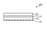
A.位相差層付偏光板の全体構成
図1は、本発明の1つの実施形態による位相差層付偏光板の概略断面図である。本実施形態の位相差層付偏光板100は、偏光板10と位相差層20とを有する。偏光板10は、偏光膜11と、偏光膜11の一方の側に配置された第1の保護層12と、偏光膜11のもう一方の側に配置された第2の保護層13とを含む。目的に応じて、第1の保護層12および第2の保護層13の一方は省略されてもよい。例えば、位相差層20が偏光膜11の保護層としても機能し得る場合には、第2の保護層13は省略されてもよい。本発明の実施形態においては、偏光膜は、二色性物質を含むポリビニルアルコール系樹脂フィルムで構成される。偏光膜の厚みは8μm以下であり、単体透過率が45%以上であり、偏光度が97%以上である。
A. Overall Configuration of Retardation Layer-Equipped Polarizing Plate FIG. 1 is a schematic cross-sectional view of a retardation layer-attached polarizing plate according to one embodiment of the present invention. A polarizing
図2に示すように、別の実施形態による位相差層付偏光板101においては、別の位相差層50ならびに/あるいは導電層または導電層付等方性基材60が設けられてもよい。別の位相差層50ならびに導電層または導電層付等方性基材60は、代表的には、位相差層20の外側(偏光板10と反対側)に設けられる。別の位相差層は、代表的には、屈折率特性がnz>nx=nyの関係を示す。別の位相差層50ならびに導電層または導電層付等方性基材60は、代表的には、位相差層20側からこの順に設けられる。別の位相差層50ならびに導電層または導電層付等方性基材60は、代表的には、必要に応じて設けられる任意の層であり、いずれか一方または両方が省略されてもよい。なお、便宜上、位相差層20を第1の位相差層と称し、別の位相差層50を第2の位相差層と称する場合がある。なお、導電層または導電層付等方性基材が設けられる場合、位相差層付偏光板は、画像表示セル(例えば、有機ELセル)と偏光板との間にタッチセンサが組み込まれた、いわゆるインナータッチパネル型入力表示装置に適用され得る。
As shown in FIG. 2, in a retardation layer-attached polarizing
本発明の実施形態においては、第1の位相差層20は液晶化合物の配向固化層である。第1の位相差層20は図1および図2に示すような配向固化層の単一層であってもよく、図3に示すような第1の配向固化層21と第2の配向固化層22との積層構造を有していてもよい。
In the embodiment of the present invention, the
上記の実施形態は適宜組み合わせてもよく、上記の実施形態における構成要素に当業界で自明の改変を加えてもよい。例えば、図3の位相差層付偏光板102に第2の位相差層50ならびに/あるいは導電層または導電層付等方性基材60が設けられてもよい。また例えば、第2の位相差層50の外側に導電層付等方性基材60を設ける構成を、光学的に等価な構成(例えば、第2の位相差層と導電層との積層体)に置き換えてもよい。
The above-described embodiments may be combined as appropriate, and the constituent elements in the above-described embodiments may be modified as is obvious in the art. For example, the
本発明の実施形態による位相差層付偏光板は、その他の位相差層をさらに含んでいてもよい。その他の位相差層の光学的特性(例えば、屈折率特性、面内位相差、Nz係数、光弾性係数)、厚み、配置位置等は、目的に応じて適切に設定され得る。 The retardation layer-attached polarizing plate according to the embodiment of the present invention may further include other retardation layers. Other optical properties of the retardation layer (for example, refractive index properties, in-plane retardation, Nz coefficient, photoelastic coefficient), thickness, arrangement position, etc. can be appropriately set according to the purpose.
本発明の位相差層付偏光板は、枚葉状であってもよく長尺状であってもよい。本明細書において「長尺状」とは、幅に対して長さが十分に長い細長形状を意味し、例えば、幅に対して長さが10倍以上、好ましくは20倍以上の細長形状を含む。長尺状の位相差層付偏光板は、ロール状に巻回可能である。 The retardation layer-attached polarizing plate of the present invention may be sheet-shaped or long-shaped. As used herein, the term "long shape" means an elongated shape whose length is sufficiently long relative to its width, for example, an elongated shape whose length is 10 times or more, preferably 20 times or more, its width. include. The elongated retardation layer-attached polarizing plate can be wound into a roll.
実用的には、位相差層の偏光板と反対側には粘着剤層(図示せず)が設けられ、位相差層付偏光板は画像表示セルに貼り付け可能とされている。さらに、粘着剤層の表面には、位相差層付偏光板が使用に供されるまで、剥離フィルムが仮着されていることが好ましい。剥離フィルムを仮着することにより、粘着剤層を保護するとともに、ロール形成が可能となる。 Practically, an adhesive layer (not shown) is provided on the side of the retardation layer opposite to the polarizing plate, so that the polarizing plate with the retardation layer can be attached to the image display cell. Furthermore, it is preferable that a release film is temporarily attached to the surface of the pressure-sensitive adhesive layer until the polarizing plate with the retardation layer is used. Temporarily attaching the release film protects the pressure-sensitive adhesive layer and enables roll formation.
位相差層付偏光板の総厚みは、好ましくは60μm以下であり、より好ましくは55μm以下であり、さらに好ましくは50μm以下であり、特に好ましくは40μm以下である。総厚みの下限は、例えば28μmであり得る。本発明の実施形態によれば、このようにきわめて薄い位相差層付偏光板を実現することができる。このような位相差層付偏光板は、きわめて優れた可撓性および折り曲げ耐久性を有し得る。このような位相差層付偏光板は、湾曲した画像表示装置および/または屈曲もしくは折り曲げ可能な画像表示装置に特に好適に適用され得る。なお、位相差層付偏光板の総厚みとは、偏光板をパネルやガラスなどの外部被着体と密着させるための粘着剤層を除き、位相差層付偏光板を構成するすべての層の厚みの合計をいう(すなわち、位相差層付偏光板の総厚みは、位相差層付偏光板を画像表示セル等の隣接部材に貼り付けるための粘着剤層およびその表面に仮着され得る剥離フィルムの厚みを含まない)。 The total thickness of the retardation layer-attached polarizing plate is preferably 60 μm or less, more preferably 55 μm or less, still more preferably 50 μm or less, and particularly preferably 40 μm or less. A lower limit for the total thickness can be, for example, 28 μm. According to the embodiment of the present invention, a polarizing plate with such an extremely thin retardation layer can be realized. Such a retardation layer-attached polarizing plate can have extremely excellent flexibility and bending durability. Such a retardation layer-attached polarizing plate can be particularly suitably applied to a curved image display device and/or a bendable or foldable image display device. The total thickness of the retardation layer-equipped polarizing plate refers to the total thickness of all layers composing the retardation layer-equipped polarizing plate, excluding the adhesive layer for adhering the polarizing plate to an external adherend such as a panel or glass. The total thickness (that is, the total thickness of the retardation layer-attached polarizing plate is the pressure-sensitive adhesive layer for attaching the retardation layer-attached polarizing plate to an adjacent member such as an image display cell, and the peeling that can be temporarily attached to the surface (not including film thickness).
本発明の実施形態による位相差層付偏光板の単位重量は、例えば6.5mg/cm2以下であり、好ましくは2.0mg/cm2~6.0mg/cm2であり、より好ましくは3.0mg/cm2~5.5mg/cm2、さらに好ましくは3.5mg/cm2~5.0mg/cm2である。表示パネルが薄型である場合、位相差層付偏光板の重量によってパネルが微少に変形し、表示不良が生じるおそれがあるところ、6.5mg/cm2以下の単位重量を有する位相差層付偏光板によれば、このようなパネルの変形を防止することができる。また、上記単位重量を有する位相差層付偏光板は、薄型化した場合であっても取扱性が良好であり、かつ、きわめて優れた可撓性および折り曲げ耐久性を発揮し得る。 The unit weight of the retardation layer-attached polarizing plate according to the embodiment of the present invention is, for example, 6.5 mg/cm 2 or less, preferably 2.0 mg/cm 2 to 6.0 mg/cm 2 , more preferably 3 0 mg/cm 2 to 5.5 mg/cm 2 , more preferably 3.5 mg/cm 2 to 5.0 mg/cm 2 . When the display panel is thin, the weight of the retardation layer-attached polarizing plate may slightly deform the panel, resulting in display failure. The plate can prevent such deformation of the panel. Further, the polarizing plate with a retardation layer having the above unit weight is easy to handle even when it is made thin, and can exhibit extremely excellent flexibility and bending durability.
以下、位相差層付偏光板の構成要素について、より詳細に説明する。 The constituent elements of the retardation layer-attached polarizing plate will be described in more detail below.
B.偏光板
B-1.偏光膜
偏光膜11は、上記のとおり、厚みが8μm以下であり、単体透過率が45%以上であり、偏光度が97%以上である。一般的に、単体透過率と偏光度とは互いにトレードオフの関係にあり、単体透過率を高めると偏光度が低下し得、偏光度を高めると単体透過率が低下し得る。このため、従来、単体透過率45%以上、かつ、偏光度97%以上の光学特性を満足する薄型の偏光膜を実用に供するのは困難であった。単体透過率が45%以上であり、かつ、偏光度が97%以上であるという優れた光学特性を有するとともに光学特性のバラつきが抑制された薄型の偏光膜を用いることが、本発明の特徴の1つである。
B. Polarizing plate B-1. Polarizing Film As described above, the
偏光膜の厚みは、好ましくは1μm~8μmであり、より好ましくは1μm~7μmであり、さらに好ましくは2μm~5μmである。 The thickness of the polarizing film is preferably 1 μm to 8 μm, more preferably 1 μm to 7 μm, still more preferably 2 μm to 5 μm.
偏光膜は、好ましくは、波長380nm~780nmのいずれかの波長で吸収二色性を示す。偏光膜の単体透過率は、好ましくは46%以下である。偏光膜の偏光度は、好ましくは97.5%以上であり、より好ましくは98%以上である。一方で、偏光度は、好ましくは99%以下である。上記単体透過率は、代表的には、紫外可視分光光度計を用いて測定し、視感度補正を行なったY値である。上記偏光度は、代表的には、紫外可視分光光度計を用いて測定して視感度補正を行なった平行透過率Tpおよび直交透過率Tcに基づいて、下記式により求められる。
偏光度(%)={(Tp-Tc)/(Tp+Tc)}1/2×100
The polarizing film preferably exhibits absorption dichroism at any wavelength of 380 nm to 780 nm. The single transmittance of the polarizing film is preferably 46% or less. The polarization degree of the polarizing film is preferably 97.5% or more, more preferably 98% or more. On the other hand, the degree of polarization is preferably 99% or less. The single transmittance is typically a Y value measured using an ultraviolet-visible spectrophotometer and subjected to visibility correction. The degree of polarization is typically obtained by the following formula based on the parallel transmittance Tp and the orthogonal transmittance Tc measured using an ultraviolet-visible spectrophotometer and subjected to visibility correction.
Degree of polarization (%) = {(Tp-Tc)/(Tp+Tc)} 1/2 × 100
1つの実施形態においては、8μm以下の薄型の偏光膜の透過率は、代表的には、偏光膜(表面の屈折率:1.53)と保護フィルム(屈折率:1.50)との積層体を測定対象として、紫外可視分光光度計を用いて測定される。偏光膜の表面の屈折率および/または保護フィルムの空気界面に接する表面の屈折率に応じて、各層の界面での反射率が変化し、その結果、透過率の測定値が変化する場合がある。したがって、例えば、屈折率が1.50ではない保護フィルムを用いる場合、保護フィルムの空気界面に接する表面の屈折率に応じて透過率の測定値を補正してもよい。具体的には、透過率の補正値Cは、保護フィルムと空気層との界面における透過軸に平行な偏光の反射率R1(透過軸反射率)を用いて、以下の式で表わされる。
C=R1-R0
R0=((1.50-1)2/(1.50+1)2)×(T1/100)
R1=((n1-1)2/(n1+1)2)×(T1/100)
ここで、R0は、屈折率が1.50である保護フィルムを用いた場合の透過軸反射率であり、n1は使用する保護フィルムの屈折率であり、T1は偏光膜の透過率である。例えば、表面屈折率が1.53である基材(シクロオレフィン系フィルム、ハードコート層付きフィルムなど)を保護フィルムとして用いる場合、補正量Cは約0.2%となる。この場合、測定により得られた透過率に0.2%を加算することで、表面屈折率が1.50である保護フィルムを用いた場合の透過率に換算することが可能である。なお、上記式に基づく計算によれば、偏光膜の透過率T1を2%変化させたときの補正値Cの変化量は0.03%以下であり、偏光膜の透過率が補正値Cの値に与える影響は限定的である。また、保護フィルムが表面反射以外の吸収を有する場合は、吸収量に応じて適切な補正を行うことができる。
In one embodiment, the transmittance of a thin polarizing film of 8 μm or less is typically a laminate of a polarizing film (surface refractive index: 1.53) and a protective film (refractive index: 1.50) It is measured using an ultraviolet-visible spectrophotometer with the body as the measurement target. Depending on the refractive index of the surface of the polarizing film and/or the refractive index of the surface of the protective film in contact with the air interface, the reflectance at each layer interface may change, resulting in a change in the measured transmittance. . Thus, for example, if a protective film with a refractive index not equal to 1.50 is used, the transmittance measurements may be corrected according to the refractive index of the surface of the protective film in contact with the air interface. Specifically, the transmittance correction value C is expressed by the following formula using the reflectance R 1 (transmission axis reflectance) of polarized light parallel to the transmission axis at the interface between the protective film and the air layer.
C=R 1 -R 0
R 0 = ((1.50−1) 2 /(1.50+1) 2 )×(T 1 /100)
R 1 = ((n 1 −1) 2 /(n 1 +1) 2 )×(T 1 /100)
Here, R 0 is the transmission axis reflectance when a protective film having a refractive index of 1.50 is used, n 1 is the refractive index of the protective film used, and T 1 is the transmittance of the polarizing film. is. For example, when a substrate having a surface refractive index of 1.53 (a cycloolefin film, a film with a hard coat layer, etc.) is used as the protective film, the correction amount C is approximately 0.2%. In this case, by adding 0.2% to the transmittance obtained by the measurement, it is possible to convert the transmittance into the transmittance when using a protective film having a surface refractive index of 1.50. According to the calculation based on the above formula, the amount of change in the correction value C when the transmittance T1 of the polarizing film is changed by 2% is 0.03% or less, and the transmittance of the polarizing film is equal to the correction value C has a limited effect on the value of Moreover, when the protective film has absorption other than surface reflection, appropriate correction can be performed according to the amount of absorption.
1つの実施形態においては、位相差層付偏光板は幅が1000mm以上であり、したがって、偏光膜の幅も1000mm以上である。この場合、偏光膜の幅方向に沿った位置における単体透過率の最大値と最小値との差(D1)は、好ましくは0.5%以下であり、より好ましくは0.4%以下であり、さらに好ましくは0.3%以下である。D1は小さければ小さいほど好ましく、D1の下限は例えば0.01%であり得る。D1が上記の範囲内であれば、優れた光学特性を有する位相差層付偏光板を工業的に生産することができる。別の実施形態においては、偏光膜は、50cm2の領域内における単体透過率の最大値と最小値との差(D2)が好ましくは0.2%以下であり、より好ましくは0.15%以下であり、さらに好ましくは0.1%以下である。D2は小さければ小さいほど好ましく、D2の下限は例えば0.01%であり得る。D2が上記の範囲内であれば、位相差層付偏光板を画像表示装置に用いたときに表示画面における輝度のバラつきを抑制することができる。 In one embodiment, the retardation layer-attached polarizing plate has a width of 1000 mm or more, and therefore the width of the polarizing film is also 1000 mm or more. In this case, the difference (D1) between the maximum and minimum single transmittance values at positions along the width direction of the polarizing film is preferably 0.5% or less, more preferably 0.4% or less. , more preferably 0.3% or less. D1 is preferably as small as possible, and the lower limit of D1 can be, for example, 0.01%. When D1 is within the above range, a polarizing plate with a retardation layer having excellent optical properties can be industrially produced. In another embodiment, the polarizing film preferably has a difference (D2) between the maximum and minimum values of single transmittance in an area of 50 cm 2 of 0.2% or less, more preferably 0.15%. or less, more preferably 0.1% or less. D2 is preferably as small as possible, and the lower limit of D2 can be, for example, 0.01%. If D2 is within the above range, it is possible to suppress variations in luminance on a display screen when the polarizing plate with a retardation layer is used in an image display device.
偏光膜としては、任意の適切な偏光膜が採用され得る。偏光膜は、代表的には、二層以上の積層体を用いて作製され得る。 Any appropriate polarizing film can be employed as the polarizing film. A polarizing film can typically be produced using a laminate of two or more layers.
積層体を用いて得られる偏光膜の具体例としては、樹脂基材と当該樹脂基材に塗布形成されたPVA系樹脂層との積層体を用いて得られる偏光膜が挙げられる。樹脂基材と当該樹脂基材に塗布形成されたPVA系樹脂層との積層体を用いて得られる偏光膜は、例えば、PVA系樹脂溶液を樹脂基材に塗布し、乾燥させて樹脂基材上にPVA系樹脂層を形成して、樹脂基材とPVA系樹脂層との積層体を得ること;当該積層体を延伸および染色してPVA系樹脂層を偏光膜とすること;により作製され得る。本実施形態においては、延伸は、代表的には積層体をホウ酸水溶液中に浸漬させて延伸することを含む。さらに、延伸は、必要に応じて、ホウ酸水溶液中での延伸の前に積層体を高温(例えば、95℃以上)で空中延伸することをさらに含み得る。得られた樹脂基材/偏光膜の積層体はそのまま用いてもよく(すなわち、樹脂基材を偏光膜の保護層としてもよく)、樹脂基材/偏光膜の積層体から樹脂基材を剥離し、当該剥離面に目的に応じた任意の適切な保護層を積層して用いてもよい。このような偏光膜の製造方法の詳細は、例えば特開2012-73580号公報に記載されている。当該公報は、その全体の記載が本明細書に参考として援用される。 A specific example of a polarizing film obtained using a laminate is a polarizing film obtained using a laminate of a resin substrate and a PVA-based resin layer formed by coating on the resin substrate. A polarizing film obtained by using a laminate of a resin base material and a PVA-based resin layer formed by coating on the resin base material can be obtained, for example, by applying a PVA-based resin solution to the resin base material and drying the resin base material. forming a PVA-based resin layer thereon to obtain a laminate of a resin substrate and a PVA-based resin layer; stretching and dyeing the laminate to make the PVA-based resin layer a polarizing film; obtain. In this embodiment, stretching typically includes immersing the laminate in an aqueous boric acid solution and stretching. Furthermore, stretching may further include stretching the laminate in air at a high temperature (eg, 95° C. or higher) before stretching in an aqueous boric acid solution, if necessary. The obtained resin substrate/polarizing film laminate may be used as it is (that is, the resin substrate may be used as a protective layer for the polarizing film), or the resin substrate may be peeled off from the resin substrate/polarizing film laminate. Then, any appropriate protective layer may be laminated on the release surface according to the purpose. Details of a method for manufacturing such a polarizing film are described in, for example, Japanese Patent Application Laid-Open No. 2012-73580. The publication is incorporated herein by reference in its entirety.
偏光膜の製造方法は、代表的には、長尺状の熱可塑性樹脂基材の片側に、ハロゲン化物とポリビニルアルコール系樹脂とを含むポリビニルアルコール系樹脂層を形成して積層体とすること、および、上記積層体に、空中補助延伸処理と、染色処理と、水中延伸処理と、長手方向に搬送しながら加熱することにより幅方向に2%以上収縮させる乾燥収縮処理と、をこの順に施すことを含む。これにより、厚みが8μm以下であり、単体透過率が45%以上であり、偏光度が97%以上である、優れた光学特性を有するとともに光学特性のバラつきが抑制された偏光膜が提供され得る。すなわち、補助延伸を導入することにより、熱可塑性樹脂上にPVAを塗布する場合でも、PVAの結晶性を高めることが可能となり、高い光学特性を達成することが可能となる。また、同時にPVAの配向性を事前に高めることで、後の染色工程や延伸工程で水に浸漬された時に、PVAの配向性の低下や溶解などの問題を防止することができ、高い光学特性を達成することが可能になる。さらに、PVA系樹脂層を液体に浸漬した場合において、PVA系樹脂層がハロゲン化物を含まない場合に比べて、ポリビニルアルコール分子の配向の乱れ、および配向性の低下が抑制され得る。これにより、染色処理および水中延伸処理など、積層体を液体に浸漬して行う処理工程を経て得られる偏光膜の光学特性を向上し得る。さらに、乾燥収縮処理により積層体を幅方向に収縮させることにより、光学特性を向上させることができる。 A representative method for producing a polarizing film is to form a laminate by forming a polyvinyl alcohol-based resin layer containing a halide and a polyvinyl alcohol-based resin on one side of a long thermoplastic resin substrate, Then, the laminate is subjected in this order to an in-air auxiliary stretching process, a dyeing process, an underwater stretching process, and a drying shrinkage process that shrinks the laminate by 2% or more in the width direction by heating while being transported in the longitudinal direction. including. As a result, a polarizing film having a thickness of 8 μm or less, a single transmittance of 45% or more, and a degree of polarization of 97% or more, having excellent optical properties and suppressing variation in optical properties can be provided. . That is, by introducing auxiliary stretching, it becomes possible to improve the crystallinity of PVA even when PVA is coated on a thermoplastic resin, and to achieve high optical properties. At the same time, by increasing the orientation of PVA in advance, it is possible to prevent problems such as deterioration of orientation and dissolution of PVA when immersed in water in the subsequent dyeing process or stretching process, resulting in high optical properties. can be achieved. Furthermore, when the PVA-based resin layer is immersed in a liquid, disturbance of the orientation of the polyvinyl alcohol molecules and deterioration of the orientation can be suppressed as compared with the case where the PVA-based resin layer does not contain a halide. This can improve the optical properties of the polarizing film obtained through treatment steps such as dyeing treatment and underwater stretching treatment in which the laminate is immersed in a liquid. Furthermore, the optical properties can be improved by shrinking the laminate in the width direction by drying shrinkage treatment.
B-2.保護層
第1の保護層12および第2の保護層13は、それぞれ、偏光膜の保護層として使用できる任意の適切なフィルムで形成される。当該フィルムの主成分となる材料の具体例としては、トリアセチルセルロース(TAC)等のセルロース系樹脂や、ポリエステル系、ポリビニルアルコール系、ポリカーボネート系、ポリアミド系、ポリイミド系、ポリエーテルスルホン系、ポリスルホン系、ポリスチレン系、ポリノルボルネン系、ポリオレフィン系、(メタ)アクリル系、アセテート系等の透明樹脂等が挙げられる。また、(メタ)アクリル系、ウレタン系、(メタ)アクリルウレタン系、エポキシ系、シリコーン系等の熱硬化型樹脂または紫外線硬化型樹脂等も挙げられる。この他にも、例えば、シロキサン系ポリマー等のガラス質系ポリマーも挙げられる。また、特開2001-343529号公報(WO01/37007)に記載のポリマーフィルムも使用できる。このフィルムの材料としては、例えば、側鎖に置換または非置換のイミド基を有する熱可塑性樹脂と、側鎖に置換または非置換のフェニル基ならびにニトリル基を有する熱可塑性樹脂を含有する樹脂組成物が使用でき、例えば、イソブテンとN-メチルマレイミドからなる交互共重合体と、アクリロニトリル・スチレン共重合体とを有する樹脂組成物が挙げられる。当該ポリマーフィルムは、例えば、上記樹脂組成物の押出成形物であり得る。
B-2. Protective Layers First
本発明の位相差層付偏光板は、後述するように代表的には画像表示装置の視認側に配置され、第1の保護層12は、代表的にはその視認側に配置される。したがって、第1の保護層12には、必要に応じて、ハードコート処理、反射防止処理、スティッキング防止処理、アンチグレア処理等の表面処理が施されていてもよい。さらに/あるいは、第1の保護層12には、必要に応じて、偏光サングラスを介して視認する場合の視認性を改善する処理(代表的には、(楕)円偏光機能を付与すること、超高位相差を付与すること)が施されていてもよい。このような処理を施すことにより、偏光サングラス等の偏光レンズを介して表示画面を視認した場合でも、優れた視認性を実現することができる。したがって、位相差層付偏光板は、屋外で用いられ得る画像表示装置にも好適に適用され得る。
The retardation layer-attached polarizing plate of the present invention is typically arranged on the viewing side of an image display device, and the first
第1の保護層の厚みは、好ましくは5μm~80μm、より好ましくは10μm~40μm、さらに好ましくは10μm~30μmである。なお、表面処理が施されている場合、外側保護層の厚みは、表面処理層の厚みを含めた厚みである。 The thickness of the first protective layer is preferably 5 μm to 80 μm, more preferably 10 μm to 40 μm, still more preferably 10 μm to 30 μm. In addition, when the surface treatment is performed, the thickness of the outer protective layer is the thickness including the thickness of the surface treatment layer.
第2の保護層13は、1つの実施形態においては、光学的に等方性であることが好ましい。本明細書において「光学的に等方性である」とは、面内位相差Re(550)が0nm~10nmであり、厚み方向の位相差Rth(550)が-10nm~+10nmであることをいう。第2の保護層13は、1つの実施形態においては、任意の適切な位相差値を有する位相差層であり得る。この場合、位相差層の面内位相差Re(550)は、例えば110nm~150nmである。第2の保護層の厚みは、好ましくは5μm~80μm、より好ましくは10μm~40μm、さらに好ましくは10μm~30μmである。薄型化および軽量化の観点からは、好ましくは第2の保護層は省略され得る。
Second
B-3.偏光膜の製造方法
偏光膜は、例えば、長尺状の熱可塑性樹脂基材の片側に、ハロゲン化物とポリビニルアルコール系樹脂(PVA系樹脂)とを含むポリビニルアルコール系樹脂層(PVA系樹脂層)を形成して積層体とすること、および、積層体に、空中補助延伸処理と、染色処理と、水中延伸処理と、長手方向に搬送しながら加熱することにより幅方向に2%以上収縮させる乾燥収縮処理と、をこの順に施すことを含む方法により作製され得る。PVA系樹脂層におけるハロゲン化物の含有量は、好ましくは、PVA系樹脂100重量部に対して5重量部~20重量部である。乾燥収縮処理は、加熱ロールを用いて処理することが好ましく、加熱ロールの温度は、好ましくは、60℃~120℃である。乾燥収縮処理による積層体の幅方向の収縮率は、好ましくは、2%以上である。このような製造方法によれば、上記B-1項で説明した偏光膜を得ることができる。特に、ハロゲン化物を含むPVA系樹脂層を含む積層体を作製し、上記積層体の延伸を空中補助延伸及び水中延伸を含む多段階延伸とし、延伸後の積層体を加熱ロールで加熱することにより、優れた光学特性(代表的には、単体透過率および偏光度)を有するとともに、光学特性のバラつきが抑制された偏光膜を得ることができる。具体的には、乾燥収縮処理工程において加熱ロールを用いることにより、積層体を搬送しながら、積層体全体に亘って均一に収縮することができる。これにより、得られる偏光膜の光学特性を高めることができるだけでなく、光学特性に優れる偏光膜を安定して生産することができ、偏光膜の光学特性(特に、単体透過率)のバラつきを抑制することができる。
B-3. Method for manufacturing polarizing film The polarizing film is formed by, for example, forming a polyvinyl alcohol-based resin layer (PVA-based resin layer) containing a halide and a polyvinyl alcohol-based resin (PVA-based resin) on one side of a long thermoplastic resin substrate. is formed to form a laminate, and the laminate is subjected to aerial auxiliary stretching treatment, dyeing treatment, underwater stretching treatment, and heating while conveying in the longitudinal direction to shrink by 2% or more in the width direction Drying and shrinkage treatment in this order. The content of the halide in the PVA-based resin layer is preferably 5 to 20 parts by weight with respect to 100 parts by weight of the PVA-based resin. The drying shrinkage treatment is preferably performed using a heating roll, and the temperature of the heating roll is preferably 60°C to 120°C. The shrinkage ratio in the width direction of the laminate due to drying shrinkage treatment is preferably 2% or more. According to such a manufacturing method, the polarizing film described in the above section B-1 can be obtained. In particular, a laminate containing a PVA-based resin layer containing a halide is produced, the laminate is stretched in multiple stages including auxiliary stretching in the air and stretching in water, and the laminate after stretching is heated with a heating roll. It is possible to obtain a polarizing film having excellent optical properties (typically, single transmittance and degree of polarization) and suppressed variations in optical properties. Specifically, by using a heating roll in the drying shrinkage treatment step, the entire laminate can be uniformly shrunk while being transported. As a result, it is possible not only to improve the optical properties of the obtained polarizing film, but also to stably produce a polarizing film with excellent optical properties, and to suppress variations in the optical properties of the polarizing film (in particular, the transmittance of a single unit). can do.
B-3-1.積層体の作製
熱可塑性樹脂基材とPVA系樹脂層との積層体を作製する方法としては、任意の適切な方法が採用され得る。好ましくは、熱可塑性樹脂基材の表面に、ハロゲン化物とPVA系樹脂とを含む塗布液を塗布し、乾燥することにより、熱可塑性樹脂基材上にPVA系樹脂層を形成する。上記のとおり、PVA系樹脂層におけるハロゲン化物の含有量は、好ましくは、PVA系樹脂100重量部に対して5重量部~20重量部である。
B-3-1. Production of Laminate Any appropriate method can be adopted as a method for producing a laminate of a thermoplastic resin substrate and a PVA-based resin layer. Preferably, a coating liquid containing a halide and a PVA-based resin is applied to the surface of the thermoplastic resin substrate and dried to form a PVA-based resin layer on the thermoplastic resin substrate. As described above, the content of the halide in the PVA-based resin layer is preferably 5 to 20 parts by weight with respect to 100 parts by weight of the PVA-based resin.
塗布液の塗布方法としては、任意の適切な方法を採用することができる。例えば、ロールコート法、スピンコート法、ワイヤーバーコート法、ディップコート法、ダイコート法、カーテンコート法、スプレーコート法、ナイフコート法(コンマコート法等)等が挙げられる。上記塗布液の塗布・乾燥温度は、好ましくは50℃以上である。 Any appropriate method can be adopted as a method for applying the coating liquid. Examples thereof include roll coating, spin coating, wire bar coating, dip coating, die coating, curtain coating, spray coating, and knife coating (comma coating, etc.). The coating/drying temperature of the coating liquid is preferably 50° C. or higher.
PVA系樹脂層の厚みは、好ましくは、3μm~40μm、さらに好ましくは3μm~20μmである。 The thickness of the PVA-based resin layer is preferably 3 μm to 40 μm, more preferably 3 μm to 20 μm.
PVA系樹脂層を形成する前に、熱可塑性樹脂基材に表面処理(例えば、コロナ処理等)を施してもよいし、熱可塑性樹脂基材上に易接着層を形成してもよい。このような処理を行うことにより、熱可塑性樹脂基材とPVA系樹脂層との密着性を向上させることができる。 Before forming the PVA-based resin layer, the thermoplastic resin substrate may be surface-treated (for example, corona treatment), or an easy-adhesion layer may be formed on the thermoplastic resin substrate. By performing such treatment, the adhesion between the thermoplastic resin substrate and the PVA-based resin layer can be improved.
B-3-1-1.熱可塑性樹脂基材
熱可塑性樹脂基材の厚みは、好ましくは20μm~300μm、より好ましくは50μm~200μmである。20μm未満であると、PVA系樹脂層の形成が困難になるおそれがある。300μmを超えると、例えば、後述の水中延伸処理において、熱可塑性樹脂基材が水を吸収するのに長時間を要するとともに、延伸に過大な負荷を要するおそれがある。
B-3-1-1. Thermoplastic Resin Substrate The thickness of the thermoplastic resin substrate is preferably 20 μm to 300 μm, more preferably 50 μm to 200 μm. If the thickness is less than 20 μm, it may be difficult to form the PVA-based resin layer. If it exceeds 300 μm, for example, in the later-described underwater stretching treatment, it may take a long time for the thermoplastic resin substrate to absorb water, and an excessive load may be required for stretching.
熱可塑性樹脂基材は、好ましくは、その吸水率が0.2%以上であり、さらに好ましくは0.3%以上である。熱可塑性樹脂基材は、水を吸収し、水が可塑剤的な働きをして可塑化し得る。その結果、延伸応力を大幅に低下させることができ、高倍率に延伸することができる。一方、熱可塑性樹脂基材の吸水率は、好ましくは3.0%以下、さらに好ましくは1.0%以下である。このような熱可塑性樹脂基材を用いることにより、製造時に熱可塑性樹脂基材の寸法安定性が著しく低下して、得られる偏光膜の外観が悪化するなどの不具合を防止することができる。また、水中延伸時に基材が破断したり、熱可塑性樹脂基材からPVA系樹脂層が剥離したりするのを防止することができる。なお、熱可塑性樹脂基材の吸水率は、例えば、構成材料に変性基を導入することにより調整することができる。吸水率は、JIS K 7209に準じて求められる値である。 The thermoplastic resin substrate preferably has a water absorption of 0.2% or more, more preferably 0.3% or more. Thermoplastic resin substrates can absorb water and be plasticized with water acting like a plasticizer. As a result, the stretching stress can be greatly reduced, and the film can be stretched at a high draw ratio. On the other hand, the water absorption rate of the thermoplastic resin substrate is preferably 3.0% or less, more preferably 1.0% or less. By using such a thermoplastic resin substrate, it is possible to prevent problems such as deterioration in the appearance of the obtained polarizing film due to a marked decrease in the dimensional stability of the thermoplastic resin substrate during production. In addition, it is possible to prevent breakage of the base material and separation of the PVA-based resin layer from the thermoplastic resin base material during stretching in water. The water absorption rate of the thermoplastic resin substrate can be adjusted, for example, by introducing a modifying group into the constituent material. The water absorption is a value determined according to JIS K7209.
熱可塑性樹脂基材のガラス転移温度(Tg)は、好ましくは120℃以下である。このような熱可塑性樹脂基材を用いることにより、PVA系樹脂層の結晶化を抑制しながら、積層体の延伸性を十分に確保することができる。さらに、水による熱可塑性樹脂基材の可塑化と、水中延伸を良好に行うことを考慮すると、100℃以下、さらには90℃以下であることがより好ましい。一方、熱可塑性樹脂基材のガラス転移温度は、好ましくは60℃以上である。このような熱可塑性樹脂基材を用いることにより、上記PVA系樹脂を含む塗布液を塗布・乾燥する際に、熱可塑性樹脂基材が変形(例えば、凹凸やタルミ、シワ等の発生)するなどの不具合を防止して、良好に積層体を作製することができる。また、PVA系樹脂層の延伸を、好適な温度(例えば、60℃程度)にて良好に行うことができる。なお、熱可塑性樹脂基材のガラス転移温度は、例えば、構成材料に変性基を導入する、結晶化材料を用いて加熱することにより調整することができる。ガラス転移温度(Tg)は、JIS K 7121に準じて求められる値である。 The glass transition temperature (Tg) of the thermoplastic resin substrate is preferably 120°C or lower. By using such a thermoplastic resin substrate, it is possible to sufficiently secure the stretchability of the laminate while suppressing the crystallization of the PVA-based resin layer. Furthermore, considering the plasticization of the thermoplastic resin substrate with water and the satisfactory stretching in water, the temperature is preferably 100° C. or lower, more preferably 90° C. or lower. On the other hand, the glass transition temperature of the thermoplastic resin substrate is preferably 60°C or higher. By using such a thermoplastic resin substrate, deformation of the thermoplastic resin substrate (for example, generation of unevenness, sagging, wrinkles, etc.) occurs when the coating liquid containing the PVA-based resin is applied and dried. It is possible to prevent the problem of and produce a good laminate. Moreover, the PVA-based resin layer can be satisfactorily stretched at a suitable temperature (for example, about 60°C). The glass transition temperature of the thermoplastic resin substrate can be adjusted, for example, by heating using a crystallization material that introduces a modifying group into the constituent material. The glass transition temperature (Tg) is a value determined according to JIS K7121.
熱可塑性樹脂基材の構成材料としては、任意の適切な熱可塑性樹脂が採用され得る。熱可塑性樹脂としては、例えば、ポリエチレンテレフタレート系樹脂等のエステル系樹脂、ノルボルネン系樹脂等のシクロオレフィン系樹脂、ポリプロピレン等のオレフィン系樹脂、ポリアミド系樹脂、ポリカーボネート系樹脂、これらの共重合体樹脂等が挙げられる。これらの中でも、好ましくは、ノルボルネン系樹脂、非晶質のポリエチレンテレフタレート系樹脂である。 Any appropriate thermoplastic resin can be employed as a constituent material of the thermoplastic resin base material. Examples of thermoplastic resins include ester resins such as polyethylene terephthalate resins, cycloolefin resins such as norbornene resins, olefin resins such as polypropylene, polyamide resins, polycarbonate resins, and copolymer resins thereof. is mentioned. Among these, norbornene-based resins and amorphous polyethylene terephthalate-based resins are preferred.
1つの実施形態においては、非晶質の(結晶化していない)ポリエチレンテレフタレート系樹脂が好ましく用いられる。中でも、非晶性の(結晶化しにくい)ポリエチレンテレフタレート系樹脂が特に好ましく用いられる。非晶性のポリエチレンテレフタレート系樹脂の具体例としては、ジカルボン酸としてイソフタル酸および/またはシクロヘキサンジカルボン酸をさらに含む共重合体や、グリコールとしてシクロヘキサンジメタノールやジエチレングリコールをさらに含む共重合体が挙げられる。 In one embodiment, an amorphous (not crystallized) polyethylene terephthalate resin is preferably used. Among them, amorphous (difficult to crystallize) polyethylene terephthalate resin is particularly preferably used. Specific examples of amorphous polyethylene terephthalate resins include copolymers further containing isophthalic acid and/or cyclohexanedicarboxylic acid as dicarboxylic acids, and copolymers further containing cyclohexanedimethanol or diethylene glycol as glycols.
好ましい実施形態においては、熱可塑性樹脂基材は、イソフタル酸ユニットを有するポリエチレンテレフタレート系樹脂で構成される。このような熱可塑性樹脂基材は延伸性に極めて優れるとともに、延伸時の結晶化が抑制され得るからである。これは、イソフタル酸ユニットを導入することで、主鎖に大きな屈曲を与えることによるものと考えられる。ポリエチレンテレフタレート系樹脂は、テレフタル酸ユニットおよびエチレングリコールユニットを有する。イソフタル酸ユニットの含有割合は、全繰り返し単位の合計に対して、好ましくは0.1モル%以上、さらに好ましくは1.0モル%以上である。延伸性に極めて優れた熱可塑性樹脂基材が得られるからである。一方、イソフタル酸ユニットの含有割合は、全繰り返し単位の合計に対して、好ましくは20モル%以下、より好ましくは10モル%以下である。このような含有割合に設定することで、後述の乾燥収縮処理において結晶化度を良好に増加させることができる。 In a preferred embodiment, the thermoplastic resin base material is composed of a polyethylene terephthalate-based resin having an isophthalic acid unit. This is because such a thermoplastic resin substrate is extremely excellent in stretchability and can suppress crystallization during stretching. This is probably because the introduction of the isophthalic acid unit gives the main chain a large bend. A polyethylene terephthalate-based resin has a terephthalic acid unit and an ethylene glycol unit. The isophthalic acid unit content is preferably 0.1 mol % or more, more preferably 1.0 mol % or more, relative to the total of all repeating units. This is because a thermoplastic resin base material having extremely excellent stretchability can be obtained. On the other hand, the isophthalic acid unit content is preferably 20 mol % or less, more preferably 10 mol % or less, relative to the total of all repeating units. By setting such a content ratio, the degree of crystallinity can be favorably increased in the drying shrinkage treatment described later.
熱可塑性樹脂基材は、予め(PVA系樹脂層を形成する前)、延伸されていてもよい。1つの実施形態においては、長尺状の熱可塑性樹脂基材の横方向に延伸されている。横方向は、好ましくは、後述の積層体の延伸方向に直交する方向である。なお、本明細書において、「直交」とは、実質的に直交する場合も包含する。ここで、「実質的に直交」とは、90°±5.0°である場合を包含し、好ましくは90°±3.0°、さらに好ましくは90°±1.0°である。 The thermoplastic resin substrate may be stretched in advance (before forming the PVA-based resin layer). In one embodiment, the elongated thermoplastic resin substrate is stretched in the transverse direction. The lateral direction is preferably a direction perpendicular to the stretching direction of the laminate described below. In addition, in this specification, "perpendicular" also includes the case of being substantially perpendicular. Here, "substantially orthogonal" includes 90°±5.0°, preferably 90°±3.0°, more preferably 90°±1.0°.
熱可塑性樹脂基材の延伸温度は、ガラス転移温度(Tg)に対し、好ましくはTg-10℃~Tg+50℃である。熱可塑性樹脂基材の延伸倍率は、好ましくは1.5倍~3.0倍である。 The stretching temperature of the thermoplastic resin substrate is preferably Tg-10°C to Tg+50°C with respect to the glass transition temperature (Tg). The draw ratio of the thermoplastic resin substrate is preferably 1.5 to 3.0 times.
熱可塑性樹脂基材の延伸方法としては、任意の適切な方法が採用され得る。具体的には、固定端延伸でもよいし、自由端延伸でもよい。延伸方式は、乾式でもよいし、湿式でもよい。熱可塑性樹脂基材の延伸は、一段階で行ってもよいし、多段階で行ってもよい。多段階で行う場合、上述の延伸倍率は、各段階の延伸倍率の積である。 Any appropriate method can be adopted as a method for stretching the thermoplastic resin substrate. Specifically, the drawing may be fixed end drawing or free end drawing. The stretching method may be a dry method or a wet method. The stretching of the thermoplastic resin substrate may be performed in one step or in multiple steps. When performing in multiple stages, the above-mentioned draw ratio is the product of the draw ratios in each step.
B-3-1-2.塗布液
塗布液は、上記のとおり、ハロゲン化物とPVA系樹脂とを含む。上記塗布液は、代表的には、上記ハロゲン化物および上記PVA系樹脂を溶媒に溶解させた溶液である。溶媒としては、例えば、水、ジメチルスルホキシド、ジメチルホルムアミド、ジメチルアセトアミド、N-メチルピロリドン、各種グリコール類、トリメチロールプロパン等の多価アルコール類、エチレンジアミン、ジエチレントリアミン等のアミン類が挙げられる。これらは単独で、または、二種以上組み合わせて用いることができる。これらの中でも、好ましくは、水である。溶液のPVA系樹脂濃度は、溶媒100重量部に対して、好ましくは3重量部~20重量部である。このような樹脂濃度であれば、熱可塑性樹脂基材に密着した均一な塗布膜を形成することができる。塗布液におけるハロゲン化物の含有量は、好ましくは、PVA系樹脂100重量部に対して5重量部~20重量部である。
B-3-1-2. Coating Liquid The coating liquid contains a halide and a PVA-based resin as described above. The coating liquid is typically a solution in which the halide and the PVA-based resin are dissolved in a solvent. Examples of solvents include water, dimethylsulfoxide, dimethylformamide, dimethylacetamide, N-methylpyrrolidone, various glycols, polyhydric alcohols such as trimethylolpropane, and amines such as ethylenediamine and diethylenetriamine. These can be used alone or in combination of two or more. Among these, water is preferred. The concentration of the PVA-based resin in the solution is preferably 3 to 20 parts by weight with respect to 100 parts by weight of the solvent. With such a resin concentration, it is possible to form a uniform coating film in close contact with the thermoplastic resin substrate. The content of the halide in the coating liquid is preferably 5 to 20 parts by weight with respect to 100 parts by weight of the PVA-based resin.
塗布液に、添加剤を配合してもよい。添加剤としては、例えば、可塑剤、界面活性剤等が挙げられる。可塑剤としては、例えば、エチレングリコールやグリセリン等の多価アルコールが挙げられる。界面活性剤としては、例えば、非イオン界面活性剤が挙げられる。これらは、得られるPVA系樹脂層の均一性や染色性、延伸性をより一層向上させる目的で使用され得る。 Additives may be added to the coating liquid. Examples of additives include plasticizers and surfactants. Examples of plasticizers include polyhydric alcohols such as ethylene glycol and glycerin. Surfactants include, for example, nonionic surfactants. These can be used for the purpose of further improving the uniformity, dyeability and stretchability of the obtained PVA-based resin layer.
上記PVA系樹脂としては、任意の適切な樹脂が採用され得る。例えば、ポリビニルアルコールおよびエチレン-ビニルアルコール共重合体が挙げられる。ポリビニルアルコールは、ポリ酢酸ビニルをケン化することにより得られる。エチレン-ビニルアルコール共重合体は、エチレン-酢酸ビニル共重合体をケン化することにより得られる。PVA系樹脂のケン化度は、通常85モル%~100モル%であり、好ましくは95.0モル%~99.95モル%、さらに好ましくは99.0モル%~99.93モル%である。ケン化度は、JIS K 6726-1994に準じて求めることができる。このようなケン化度のPVA系樹脂を用いることによって、耐久性に優れた偏光膜が得られ得る。ケン化度が高すぎる場合には、ゲル化してしまうおそれがある。 Any appropriate resin can be adopted as the PVA-based resin. Examples include polyvinyl alcohol and ethylene-vinyl alcohol copolymers. Polyvinyl alcohol is obtained by saponifying polyvinyl acetate. An ethylene-vinyl alcohol copolymer is obtained by saponifying an ethylene-vinyl acetate copolymer. The saponification degree of the PVA-based resin is usually 85 mol% to 100 mol%, preferably 95.0 mol% to 99.95 mol%, more preferably 99.0 mol% to 99.93 mol%. . The degree of saponification can be determined according to JIS K 6726-1994. By using a PVA-based resin having such a degree of saponification, a polarizing film with excellent durability can be obtained. If the degree of saponification is too high, gelation may occur.
PVA系樹脂の平均重合度は、目的に応じて適切に選択し得る。平均重合度は、通常1000~10000であり、好ましくは1200~4500、さらに好ましくは1500~4300である。なお、平均重合度は、JIS K 6726-1994に準じて求めることができる。 The average degree of polymerization of the PVA-based resin can be appropriately selected depending on the purpose. The average degree of polymerization is usually 1,000 to 10,000, preferably 1,200 to 4,500, more preferably 1,500 to 4,300. The average degree of polymerization can be determined according to JIS K 6726-1994.
上記ハロゲン化物としては、任意の適切なハロゲン化物が採用され得る。例えば、ヨウ化物および塩化ナトリウムが挙げられる。ヨウ化物としては、例えば、ヨウ化カリウム、ヨウ化ナトリウム、およびヨウ化リチウムが挙げられる。これらの中でも、好ましくは、ヨウ化カリウムである。 Any appropriate halide can be employed as the halide. Examples include iodide and sodium chloride. Iodides include, for example, potassium iodide, sodium iodide, and lithium iodide. Among these, potassium iodide is preferred.
塗布液におけるハロゲン化物の量は、好ましくは、PVA系樹脂100重量部に対して5重量部~20重量部であり、より好ましくは、PVA系樹脂100重量部に対して10重量部~15重量部である。PVA系樹脂100重量部に対するハロゲン化物の量が20重量部を超えると、ハロゲン化物がブリードアウトし、最終的に得られる偏光膜が白濁する場合がある。 The amount of the halide in the coating liquid is preferably 5 parts by weight to 20 parts by weight with respect to 100 parts by weight of the PVA resin, and more preferably 10 parts by weight to 15 parts by weight with respect to 100 parts by weight of the PVA resin. Department. If the amount of the halide exceeds 20 parts by weight with respect to 100 parts by weight of the PVA-based resin, the halide may bleed out and the finally obtained polarizing film may become cloudy.
一般に、PVA系樹脂層が延伸されることによって、PVA系樹脂中のポリビニルアルコール分子の配向性が高くなるが、延伸後のPVA系樹脂層を、水を含む液体に浸漬すると、ポリビニルアルコール分子の配向が乱れ、配向性が低下する場合がある。特に、熱可塑性樹脂基材とPVA系樹脂層との積層体をホウ酸水中延伸する場合において、熱可塑性樹脂基材の延伸を安定させるために比較的高い温度で上記積層体をホウ酸水中で延伸する場合、上記配向度低下の傾向が顕著である。例えば、PVAフィルム単体のホウ酸水中での延伸が60℃で行われることが一般的であるのに対し、A-PET(熱可塑性樹脂基材)とPVA系樹脂層との積層体の延伸は70℃前後の温度という高い温度で行われ、この場合、延伸初期のPVAの配向性が水中延伸により上がる前の段階で低下し得る。これに対して、ハロゲン化物を含むPVA系樹脂層と熱可塑性樹脂基材との積層体を作製し、積層体をホウ酸水中で延伸する前に空気中で高温延伸(補助延伸)することにより、補助延伸後の積層体のPVA系樹脂層中のPVA系樹脂の結晶化が促進され得る。その結果、PVA系樹脂層を液体に浸漬した場合において、PVA系樹脂層がハロゲン化物を含まない場合に比べて、ポリビニルアルコール分子の配向の乱れ、および配向性の低下が抑制され得る。これにより、染色処理および水中延伸処理など、積層体を液体に浸漬して行う処理工程を経て得られる偏光膜の光学特性を向上し得る。 In general, when the PVA-based resin layer is stretched, the orientation of the polyvinyl alcohol molecules in the PVA-based resin increases. Orientation may be disturbed and the orientation may be lowered. In particular, when a laminate of a thermoplastic resin substrate and a PVA-based resin layer is stretched in boric acid water, the laminate is stretched in boric acid water at a relatively high temperature in order to stabilize the stretching of the thermoplastic resin substrate. When the film is stretched, the tendency of the degree of orientation to decrease is remarkable. For example, the stretching of a single PVA film in boric acid water is generally carried out at 60° C., whereas the stretching of a laminate of A-PET (thermoplastic resin substrate) and a PVA-based resin layer is It is carried out at a high temperature of about 70° C., and in this case, the orientation of PVA at the initial stage of stretching may be lowered before it is increased by stretching in water. On the other hand, by preparing a laminate of a PVA-based resin layer containing a halide and a thermoplastic resin substrate and stretching the laminate at a high temperature (auxiliary stretching) in air before stretching in boric acid water, , the crystallization of the PVA-based resin in the PVA-based resin layer of the laminate after auxiliary stretching can be promoted. As a result, when the PVA-based resin layer is immersed in a liquid, the disturbance of the orientation of the polyvinyl alcohol molecules and the deterioration of the orientation can be suppressed compared to the case where the PVA-based resin layer does not contain a halide. This can improve the optical properties of the polarizing film obtained through treatment steps such as dyeing treatment and underwater stretching treatment in which the laminate is immersed in a liquid.
B-3-2.空中補助延伸処理
特に、高い光学特性を得るためには、乾式延伸(補助延伸)とホウ酸水中延伸を組み合わせる、2段延伸の方法が選択される。2段延伸のように、補助延伸を導入することにより、熱可塑性樹脂基材の結晶化を抑制しながら延伸することができ、後のホウ酸水中延伸において熱可塑性樹脂基材の過度の結晶化により延伸性が低下するという問題を解決し、積層体をより高倍率に延伸することができる。さらには、熱可塑性樹脂基材上にPVA系樹脂を塗布する場合、熱可塑性樹脂基材のガラス転移温度の影響を抑制するために、通常の金属ドラム上にPVA系樹脂を塗布する場合と比べて塗布温度を低くする必要があり、その結果、PVA系樹脂の結晶化が相対的に低くなり、十分な光学特性が得られない、という問題が生じ得る。これに対して、補助延伸を導入することにより、熱可塑性樹脂上にPVA系樹脂を塗布する場合でも、PVA系樹脂の結晶性を高めることが可能となり、高い光学特性を達成することが可能となる。また、同時にPVA系樹脂の配向性を事前に高めることで、後の染色工程や延伸工程で水に浸漬された時に、PVA系樹脂の配向性の低下や溶解などの問題を防止することができ、高い光学特性を達成することが可能になる。
B-3-2. Aerial Auxiliary Stretching In order to obtain particularly high optical properties, a two-stage stretching method combining dry stretching (auxiliary stretching) and stretching in boric acid solution is selected. By introducing auxiliary stretching, such as two-step stretching, it is possible to stretch while suppressing crystallization of the thermoplastic resin substrate, and excessive crystallization of the thermoplastic resin substrate in the subsequent stretching in boric acid water. It is possible to solve the problem that stretchability is reduced by stretching, and stretch the laminate at a higher magnification. Furthermore, when applying the PVA-based resin on the thermoplastic resin substrate, in order to suppress the influence of the glass transition temperature of the thermoplastic resin substrate, compared to the case of applying the PVA-based resin on a normal metal drum As a result, the crystallization of the PVA-based resin becomes relatively low, which may cause a problem that sufficient optical properties cannot be obtained. On the other hand, by introducing auxiliary stretching, it is possible to improve the crystallinity of the PVA-based resin even when the PVA-based resin is applied on the thermoplastic resin, and it is possible to achieve high optical properties. Become. At the same time, by increasing the orientation of the PVA-based resin in advance, it is possible to prevent problems such as deterioration of the orientation and dissolution of the PVA-based resin when it is immersed in water in the subsequent dyeing process or stretching process. , making it possible to achieve high optical properties.
空中補助延伸の延伸方法は、固定端延伸(たとえば、テンター延伸機を用いて延伸する方法)でもよいし、自由端延伸(たとえば、周速の異なるロール間に積層体を通して一軸延伸する方法)でもよいが、高い光学特性を得るためには、自由端延伸が積極的に採用され得る。1つの実施形態においては、空中延伸処理は、上記積層体をその長手方向に搬送しながら、加熱ロール間の周速差により延伸する加熱ロール延伸工程を含む。空中延伸処理は、代表的には、ゾーン延伸工程と加熱ロール延伸工程とを含む。なお、ゾーン延伸工程と加熱ロール延伸工程の順序は限定されず、ゾーン延伸工程が先に行われてもよく、加熱ロール延伸工程が先に行われてもよい。ゾーン延伸工程は省略されてもよい。1つの実施形態においては、ゾーン延伸工程および加熱ロール延伸工程がこの順に行われる。また、別の実施形態では、テンター延伸機において、フィルム端部を把持し、テンター間の距離を流れ方向に広げることで延伸される(テンター間の距離の広がりが延伸倍率となる)。この時、幅方向(流れ方向に対して、垂直方向)のテンターの距離は、任意に近づくように設定される。好ましくは、流れ方向の延伸倍率に対して、自由端延伸により近くなるように設定され得る。自由端延伸の場合、幅方向の収縮率=(1/延伸倍率)1/2で計算される。 The stretching method of the in-air auxiliary stretching may be fixed edge stretching (e.g., a method of stretching using a tenter stretching machine) or free edge stretching (e.g., a method of uniaxially stretching the laminate through rolls having different peripheral speeds). Although good, free-end stretching may be positively employed to obtain high optical properties. In one embodiment, the in-air stretching process includes a heating roll stretching step in which the laminate is stretched by a peripheral speed difference between heating rolls while being conveyed in the longitudinal direction. The air drawing process typically includes a zone drawing process and a hot roll drawing process. The order of the zone stretching process and the heating roll stretching process is not limited, and the zone stretching process may be carried out first, or the heating roll stretching process may be carried out first. The zone drawing step may be omitted. In one embodiment, the zone drawing step and the heated roll drawing step are performed in this order. In another embodiment, in a tenter stretching machine, the film is stretched by gripping the ends of the film and increasing the distance between the tenters in the machine direction (the extension of the distance between the tenters is the stretching ratio). At this time, the distance between the tenters in the width direction (perpendicular to the machine direction) is set to be arbitrarily close. Preferably, the draw ratio in the machine direction can be set to be closer to the free end draw. In the case of free end stretching, the shrinkage ratio in the width direction is calculated by (1/stretching ratio) 1/2 .
空中補助延伸は、一段階で行ってもよいし、多段階で行ってもよい。多段階で行う場合、延伸倍率は、各段階の延伸倍率の積である。空中補助延伸における延伸方向は、好ましくは、水中延伸の延伸方向と略同一である。 The in-air auxiliary stretching may be performed in one step or in multiple steps. When it is carried out in multiple stages, the draw ratio is the product of the draw ratios in each step. The stretching direction in the in-air auxiliary stretching is preferably substantially the same as the stretching direction in the underwater stretching.
空中補助延伸における延伸倍率は、好ましくは2.0倍~3.5倍である。空中補助延伸と水中延伸とを組み合わせた場合の最大延伸倍率は、積層体の元長に対して、好ましくは5.0倍以上、より好ましくは5.5倍以上、さらに好ましくは6.0倍以上である。本明細書において「最大延伸倍率」とは、積層体が破断する直前の延伸倍率をいい、別途、積層体が破断する延伸倍率を確認し、その値よりも0.2低い値をいう。 The draw ratio in the in-air auxiliary drawing is preferably 2.0 to 3.5 times. The maximum draw ratio when the auxiliary drawing in the air and the drawing in water are combined is preferably 5.0 times or more, more preferably 5.5 times or more, and still more preferably 6.0 times the original length of the laminate. That's it. As used herein, the term "maximum draw ratio" refers to the draw ratio immediately before the laminate breaks, and is 0.2 lower than the draw ratio at which the laminate breaks.
空中補助延伸の延伸温度は、熱可塑性樹脂基材の形成材料、延伸方式等に応じて、任意の適切な値に設定することができる。延伸温度は、好ましくは熱可塑性樹脂基材のガラス転移温度(Tg)以上であり、さらに好ましくは熱可塑性樹脂基材のガラス転移温度(Tg)+10℃以上、特に好ましくはTg+15℃以上である。一方、延伸温度の上限は、好ましくは170℃である。このような温度で延伸することで、PVA系樹脂の結晶化が急速に進むのを抑制して、当該結晶化による不具合(例えば、延伸によるPVA系樹脂層の配向を妨げる)を抑制することができる。空中補助延伸後のPVA系樹脂の結晶化指数は、好ましくは1.3~1.8であり、より好ましくは1.4~1.7である。PVA系樹脂の結晶化指数は、フーリエ変換赤外分光光度計を用い、ATR法により測定することができる。具体的には、偏光を測定光として測定を実施し、得られたスペクトルの1141cm-1および1440cm-1の強度を用いて、下記式に従って結晶化指数を算出する。
結晶化指数=(IC/IR)
ただし、
IC :測定光を入射して測定したときの1141cm-1の強度
IR :測定光を入射して測定したときの1440cm-1の強度
である。
The stretching temperature for the in-air auxiliary stretching can be set to any appropriate value depending on the material for forming the thermoplastic resin base material, the stretching method, and the like. The stretching temperature is preferably the glass transition temperature (Tg) of the thermoplastic resin substrate or higher, more preferably the glass transition temperature (Tg) of the thermoplastic resin substrate + 10°C or higher, and particularly preferably Tg + 15°C or higher. On the other hand, the upper limit of the stretching temperature is preferably 170°C. By stretching at such a temperature, it is possible to suppress rapid crystallization of the PVA-based resin and suppress problems caused by the crystallization (for example, hindrance of orientation of the PVA-based resin layer due to stretching). can. The crystallization index of the PVA-based resin after auxiliary stretching in air is preferably 1.3 to 1.8, more preferably 1.4 to 1.7. The crystallization index of the PVA-based resin can be measured by the ATR method using a Fourier transform infrared spectrophotometer. Specifically, measurement is performed using polarized light as measurement light, and the crystallization index is calculated according to the following formula using the intensities at 1141 cm −1 and 1440 cm −1 of the obtained spectrum.
Crystallization index = ( IC / IR )
however,
I C : Intensity at 1141 cm −1 when measurement light is incident and measured I R : Intensity at 1440 cm −1 when measurement light is incident and measured.
B-3-3.不溶化処理
必要に応じて、空中補助延伸処理の後、水中延伸処理や染色処理の前に、不溶化処理を施す。上記不溶化処理は、代表的には、ホウ酸水溶液にPVA系樹脂層を浸漬することにより行う。不溶化処理を施すことにより、PVA系樹脂層に耐水性を付与し、水に浸漬した時のPVAの配向低下を防止することができる。当該ホウ酸水溶液の濃度は、水100重量部に対して、好ましくは1重量部~4重量部である。不溶化浴(ホウ酸水溶液)の液温は、好ましくは20℃~50℃である。
B-3-3. Insolubilization Treatment If necessary, an insolubilization treatment is performed after the auxiliary stretching treatment in the air and before the stretching treatment in water or the dyeing treatment. The insolubilization treatment is typically performed by immersing the PVA-based resin layer in an aqueous boric acid solution. The insolubilization treatment imparts water resistance to the PVA-based resin layer, and prevents deterioration of the orientation of the PVA when immersed in water. The concentration of the boric acid aqueous solution is preferably 1 to 4 parts by weight with respect to 100 parts by weight of water. The liquid temperature of the insolubilizing bath (boric acid aqueous solution) is preferably 20°C to 50°C.
B-3-4.染色処理
上記染色処理は、代表的には、PVA系樹脂層を二色性物質(代表的には、ヨウ素)で染色することにより行う。具体的には、PVA系樹脂層にヨウ素を吸着させることにより行う。当該吸着方法としては、例えば、ヨウ素を含む染色液にPVA系樹脂層(積層体)を浸漬させる方法、PVA系樹脂層に当該染色液を塗工する方法、当該染色液をPVA系樹脂層に噴霧する方法等が挙げられる。好ましくは、染色液(染色浴)に積層体を浸漬させる方法である。ヨウ素が良好に吸着し得るからである。
B-3-4. Dyeing Treatment The dyeing treatment is typically performed by dyeing the PVA-based resin layer with a dichroic substance (typically iodine). Specifically, it is carried out by allowing the PVA-based resin layer to adsorb iodine. Examples of the adsorption method include a method of immersing the PVA-based resin layer (laminate) in a dyeing solution containing iodine, a method of coating the PVA-based resin layer with the dyeing solution, and a method of applying the dyeing solution to the PVA-based resin layer. A spraying method and the like can be mentioned. A preferred method is to immerse the laminate in a dyeing solution (dyeing bath). This is because iodine can be well adsorbed.
上記染色液は、好ましくは、ヨウ素水溶液である。ヨウ素の配合量は、水100重量部に対して、好ましくは0.05重量部~0.5重量部である。ヨウ素の水に対する溶解度を高めるため、ヨウ素水溶液にヨウ化物を配合することが好ましい。ヨウ化物としては、例えば、ヨウ化カリウム、ヨウ化リチウム、ヨウ化ナトリウム、ヨウ化亜鉛、ヨウ化アルミニウム、ヨウ化鉛、ヨウ化銅、ヨウ化バリウム、ヨウ化カルシウム、ヨウ化錫、ヨウ化チタン等が挙げられる。これらの中でも、好ましくは、ヨウ化カリウムである。ヨウ化物の配合量は、水100重量部に対して、好ましくは0.1重量部~10重量部、より好ましくは0.3重量部~5重量部である。染色液の染色時の液温は、PVA系樹脂の溶解を抑制するため、好ましくは20℃~50℃である。染色液にPVA系樹脂層を浸漬させる場合、浸漬時間は、PVA系樹脂層の透過率を確保するため、好ましくは5秒~5分であり、より好ましくは30秒~90秒である。 The staining solution is preferably an iodine aqueous solution. The amount of iodine compounded is preferably 0.05 to 0.5 parts by weight per 100 parts by weight of water. In order to increase the solubility of iodine in water, it is preferable to add an iodide to the iodine aqueous solution. Examples of iodides include potassium iodide, lithium iodide, sodium iodide, zinc iodide, aluminum iodide, lead iodide, copper iodide, barium iodide, calcium iodide, tin iodide, and titanium iodide. etc. Among these, potassium iodide is preferred. The amount of iodide compounded is preferably 0.1 to 10 parts by weight, more preferably 0.3 to 5 parts by weight, per 100 parts by weight of water. The liquid temperature of the dyeing liquid during dyeing is preferably 20° C. to 50° C. in order to suppress the dissolution of the PVA-based resin. When the PVA-based resin layer is immersed in the staining solution, the immersion time is preferably 5 seconds to 5 minutes, more preferably 30 seconds to 90 seconds, in order to ensure the transmittance of the PVA-based resin layer.
染色条件(濃度、液温、浸漬時間)は、最終的に得られる偏光膜の単体透過率が45%以上であり、かつ、偏光度が97%以上となるように設定することができる。このような染色条件としては、好ましくは、染色液としてヨウ素水溶液を用い、ヨウ素水溶液におけるヨウ素およびヨウ化カリウムの含有量の比を、1:5~1:20とする。ヨウ素水溶液におけるヨウ素およびヨウ化カリウムの含有量の比は、好ましくは1:5~1:10である。これにより、上記のような光学特性を有する偏光膜が得られ得る。 Dyeing conditions (concentration, liquid temperature, immersion time) can be set so that the finally obtained polarizing film has a single transmittance of 45% or more and a degree of polarization of 97% or more. As for such dyeing conditions, it is preferable to use an iodine aqueous solution as a dyeing solution and to set the content ratio of iodine and potassium iodide in the iodine aqueous solution to 1:5 to 1:20. The content ratio of iodine and potassium iodide in the aqueous iodine solution is preferably 1:5 to 1:10. Thereby, a polarizing film having the optical properties as described above can be obtained.
ホウ酸を含有する処理浴に積層体を浸漬する処理(代表的には、不溶化処理)の後に連続して染色処理を行う場合、当該処理浴に含まれるホウ酸が染色浴に混入することにより染色浴のホウ酸濃度が経時的に変化し、その結果、染色性が不安定になる場合がある。上記のような染色性の不安定化を抑制するために、染色浴のホウ酸濃度の上限は、水100重量部に対して、好ましくは4重量部、より好ましくは2重量部となるように調整される。一方で、染色浴のホウ酸濃度の下限は、水100重量部に対して、好ましくは0.1重量部であり、より好ましくは0.2重量部であり、さらに好ましくは0.5重量部である。1つの実施形態においては、予めホウ酸が配合された染色浴を用いて染色処理を行う。これにより、上記処理浴のホウ酸が染色浴に混入した場合のホウ酸濃度の変化の割合を低減し得る。予め染色浴に配合されるホウ酸の配合量(すなわち、上記処理浴に由来しないホウ酸の含有量)は、水100重量部に対して、好ましくは0.1重量部~2重量部であり、より好ましくは0.5重量部~1.5重量部である。 When dyeing treatment is performed continuously after the treatment of immersing the laminate in a treatment bath containing boric acid (typically, insolubilization treatment), the boric acid contained in the treatment bath is mixed into the dyeing bath. The boric acid concentration in the dyeing bath may change over time, resulting in unstable dyeability. In order to suppress the destabilization of dyeability as described above, the upper limit of the boric acid concentration in the dyeing bath is preferably 4 parts by weight, more preferably 2 parts by weight with respect to 100 parts by weight of water. adjusted. On the other hand, the lower limit of the boric acid concentration in the dyeing bath is preferably 0.1 parts by weight, more preferably 0.2 parts by weight, and still more preferably 0.5 parts by weight with respect to 100 parts by weight of water. is. In one embodiment, the dyeing process is performed using a dyeing bath pre-blended with boric acid. This can reduce the rate of change in boric acid concentration when the boric acid in the treatment bath is mixed into the dyeing bath. The amount of boric acid blended in advance in the dyeing bath (that is, the content of boric acid not derived from the treatment bath) is preferably 0.1 to 2 parts by weight with respect to 100 parts by weight of water. , more preferably 0.5 to 1.5 parts by weight.
B-3-5.架橋処理
必要に応じて、染色処理の後、水中延伸処理の前に、架橋処理を施す。上記架橋処理は、代表的には、ホウ酸水溶液にPVA系樹脂層を浸漬させることにより行う。架橋処理を施すことにより、PVA系樹脂層に耐水性を付与し、後の水中延伸で、高温の水中へ浸漬した際のPVAの配向低下を防止することができる。当該ホウ酸水溶液の濃度は、水100重量部に対して、好ましくは1重量部~5重量部である。また、上記染色処理後に架橋処理を行う場合、さらに、ヨウ化物を配合することが好ましい。ヨウ化物を配合することにより、PVA系樹脂層に吸着させたヨウ素の溶出を抑制することができる。ヨウ化物の配合量は、水100重量部に対して、好ましくは1重量部~5重量部である。ヨウ化物の具体例は、上述のとおりである。架橋浴(ホウ酸水溶液)の液温は、好ましくは20℃~50℃である。
B-3-5. Crosslinking Treatment If necessary, a crosslinking treatment is applied after the dyeing treatment and before the underwater stretching treatment. The cross-linking treatment is typically performed by immersing the PVA-based resin layer in an aqueous solution of boric acid. The cross-linking treatment imparts water resistance to the PVA-based resin layer, and prevents deterioration of the orientation of the PVA when immersed in high-temperature water in the subsequent underwater stretching. The concentration of the boric acid aqueous solution is preferably 1 to 5 parts by weight with respect to 100 parts by weight of water. Moreover, when cross-linking treatment is carried out after the dyeing treatment, it is preferable to further add an iodide. By blending iodide, elution of iodine adsorbed on the PVA-based resin layer can be suppressed. The amount of iodide compounded is preferably 1 to 5 parts by weight per 100 parts by weight of water. Specific examples of iodides are as described above. The liquid temperature of the cross-linking bath (boric acid aqueous solution) is preferably 20°C to 50°C.
B-3-6.水中延伸処理
水中延伸処理は、積層体を延伸浴に浸漬させて行う。水中延伸処理によれば、上記熱可塑性樹脂基材やPVA系樹脂層のガラス転移温度(代表的には、80℃程度)よりも低い温度で延伸し得、PVA系樹脂層を、その結晶化を抑えながら、高倍率に延伸することができる。その結果、優れた光学特性を有する偏光膜を製造することができる。
B-3-6. Underwater Stretching Treatment Underwater stretching treatment is performed by immersing the laminate in a stretching bath. According to the underwater stretching treatment, the thermoplastic resin substrate and the PVA-based resin layer can be stretched at a temperature lower than the glass transition temperature (typically, about 80° C.), and the PVA-based resin layer undergoes its crystallization. can be stretched at a high magnification while suppressing the As a result, a polarizing film having excellent optical properties can be produced.
積層体の延伸方法は、任意の適切な方法を採用することができる。具体的には、固定端延伸でもよいし、自由端延伸(例えば、周速の異なるロール間に積層体を通して一軸延伸する方法)でもよい。好ましくは、自由端延伸が選択される。積層体の延伸は、一段階で行ってもよいし、多段階で行ってもよい。多段階で行う場合、後述の積層体の延伸倍率(最大延伸倍率)は、各段階の延伸倍率の積である。 Any appropriate method can be adopted as a method for stretching the laminate. Specifically, fixed-end stretching or free-end stretching (for example, a method of uniaxially stretching a laminate by passing it between rolls having different peripheral speeds) may be used. Free-end drawing is preferably chosen. The laminate may be stretched in one step or in multiple steps. When the stretching is performed in multiple stages, the draw ratio (maximum draw ratio) of the laminate described below is the product of the draw ratios in each step.
水中延伸は、好ましくは、ホウ酸水溶液中に積層体を浸漬させて行う(ホウ酸水中延伸)。延伸浴としてホウ酸水溶液を用いることで、PVA系樹脂層に、延伸時にかかる張力に耐える剛性と、水に溶解しない耐水性とを付与することができる。具体的には、ホウ酸は、水溶液中でテトラヒドロキシホウ酸アニオンを生成してPVA系樹脂と水素結合により架橋し得る。その結果、PVA系樹脂層に剛性と耐水性とを付与して、良好に延伸することができ、優れた光学特性を有する偏光膜を製造することができる。 The stretching in water is preferably carried out by immersing the laminate in an aqueous boric acid solution (stretching in boric acid water). By using an aqueous boric acid solution as the stretching bath, the PVA-based resin layer can be imparted with rigidity to withstand tension applied during stretching and water resistance that does not dissolve in water. Specifically, boric acid can form a tetrahydroxyborate anion in an aqueous solution and crosslink with a PVA-based resin through hydrogen bonding. As a result, rigidity and water resistance can be imparted to the PVA-based resin layer, which can be satisfactorily stretched, and a polarizing film having excellent optical properties can be produced.
上記ホウ酸水溶液は、好ましくは、溶媒である水にホウ酸および/またはホウ酸塩を溶解させることにより得られる。ホウ酸濃度は、水100重量部に対して、好ましくは1重量部~10重量部であり、より好ましくは2.5重量部~6重量部であり、特に好ましくは3重量部~5重量部である。ホウ酸濃度を1重量部以上とすることにより、PVA系樹脂層の溶解を効果的に抑制することができ、より高特性の偏光膜を製造することができる。なお、ホウ酸またはホウ酸塩以外に、ホウ砂等のホウ素化合物、グリオキザール、グルタルアルデヒド等を溶媒に溶解して得られた水溶液も用いることができる。 The boric acid aqueous solution is preferably obtained by dissolving boric acid and/or a borate salt in water as a solvent. The boric acid concentration is preferably 1 part by weight to 10 parts by weight, more preferably 2.5 parts by weight to 6 parts by weight, and particularly preferably 3 parts by weight to 5 parts by weight, with respect to 100 parts by weight of water. is. By setting the boric acid concentration to 1 part by weight or more, the dissolution of the PVA-based resin layer can be effectively suppressed, and a polarizing film with higher properties can be produced. In addition to boric acid or borate salts, an aqueous solution obtained by dissolving a boron compound such as borax, glyoxal, glutaraldehyde, or the like in a solvent can also be used.
好ましくは、上記延伸浴(ホウ酸水溶液)にヨウ化物を配合する。ヨウ化物を配合することにより、PVA系樹脂層に吸着させたヨウ素の溶出を抑制することができる。ヨウ化物の具体例は、上述のとおりである。ヨウ化物の濃度は、水100重量部に対して、好ましくは0.05重量部~15重量部、より好ましくは0.5重量部~8重量部である。 Preferably, an iodide is added to the drawing bath (boric acid aqueous solution). By blending iodide, elution of iodine adsorbed on the PVA-based resin layer can be suppressed. Specific examples of iodides are as described above. The concentration of iodide is preferably 0.05 to 15 parts by weight, more preferably 0.5 to 8 parts by weight, per 100 parts by weight of water.
延伸温度(延伸浴の液温)は、好ましくは40℃~85℃、より好ましくは60℃~75℃である。このような温度であれば、PVA系樹脂層の溶解を抑制しながら高倍率に延伸することができる。具体的には、上述のように、熱可塑性樹脂基材のガラス転移温度(Tg)は、PVA系樹脂層の形成との関係で、好ましくは60℃以上である。この場合、延伸温度が40℃を下回ると、水による熱可塑性樹脂基材の可塑化を考慮しても、良好に延伸できないおそれがある。一方、延伸浴の温度が高温になるほど、PVA系樹脂層の溶解性が高くなって、優れた光学特性が得られないおそれがある。積層体の延伸浴への浸漬時間は、好ましくは15秒~5分である。 The stretching temperature (liquid temperature of the stretching bath) is preferably 40°C to 85°C, more preferably 60°C to 75°C. At such a temperature, the film can be stretched at a high magnification while suppressing dissolution of the PVA-based resin layer. Specifically, as described above, the glass transition temperature (Tg) of the thermoplastic resin substrate is preferably 60° C. or higher in relation to the formation of the PVA-based resin layer. In this case, if the stretching temperature is lower than 40° C., it may not be possible to stretch well even if the plasticization of the thermoplastic resin base material by water is considered. On the other hand, the higher the temperature of the stretching bath, the higher the solubility of the PVA-based resin layer, which may make it impossible to obtain excellent optical properties. The immersion time of the laminate in the stretching bath is preferably 15 seconds to 5 minutes.
水中延伸による延伸倍率は、好ましくは1.5倍以上、より好ましくは3.0倍以上である。積層体の総延伸倍率は、積層体の元長に対して、好ましくは5.0倍以上であり、さらに好ましくは5.5倍以上である。このような高い延伸倍率を達成することにより、光学特性に極めて優れた偏光膜を製造することができる。このような高い延伸倍率は、水中延伸方式(ホウ酸水中延伸)を採用することにより、達成し得る。 The draw ratio by underwater drawing is preferably 1.5 times or more, more preferably 3.0 times or more. The total draw ratio of the laminate is preferably 5.0 times or more, more preferably 5.5 times or more, relative to the original length of the laminate. By achieving such a high draw ratio, a polarizing film with extremely excellent optical properties can be produced. Such a high draw ratio can be achieved by adopting an underwater drawing method (boric acid solution drawing).
B-3-7.乾燥収縮処理
上記乾燥収縮処理は、ゾーン全体を加熱して行うゾーン加熱により行っても良いし、搬送ロールを加熱する(いわゆる加熱ロールを用いる)ことにより行う(加熱ロール乾燥方式)こともできる。好ましくは、その両方を用いる。加熱ロールを用いて乾燥させることにより、効率的に積層体の加熱カールを抑制して、外観に優れた偏光膜を製造することができる。具体的には、加熱ロールに積層体を沿わせた状態で乾燥することにより、上記熱可塑性樹脂基材の結晶化を効率的に促進させて結晶化度を増加させることができ、比較的低い乾燥温度であっても、熱可塑性樹脂基材の結晶化度を良好に増加させることができる。その結果、熱可塑性樹脂基材は、その剛性が増加して、乾燥によるPVA系樹脂層の収縮に耐え得る状態となり、カールが抑制される。また、加熱ロールを用いることにより、積層体を平らな状態に維持しながら乾燥できるので、カールだけでなくシワの発生も抑制することができる。この時、積層体は、乾燥収縮処理により幅方向に収縮させることにより、光学特性を向上させることができる。PVAおよびPVA/ヨウ素錯体の配向性を効果的に高めることができるからである。乾燥収縮処理による積層体の幅方向の収縮率は、好ましくは1%~10%であり、より好ましくは2%~8%であり、特に好ましくは4%~6%である。加熱ロールを用いることにより、積層体を搬送しながら連続的に幅方向に収縮させることができ、高い生産性を実現することができる。
B-3-7. Drying Shrinkage Treatment The drying shrinkage treatment may be performed by zone heating performed by heating the entire zone, or by heating the transport roll (using a so-called heating roll) (heated roll drying method). Preferably both are used. By drying using a heating roll, it is possible to efficiently suppress heat curling of the laminate and produce a polarizing film having an excellent appearance. Specifically, the crystallization of the thermoplastic resin substrate can be efficiently promoted and the crystallinity can be increased by drying the laminate while it is placed along the heating roll. Even at the drying temperature, the degree of crystallinity of the thermoplastic resin substrate can be favorably increased. As a result, the thermoplastic resin base material has increased rigidity and is in a state capable of withstanding shrinkage of the PVA-based resin layer due to drying, thereby suppressing curling. Moreover, by using a heating roll, the layered product can be dried while being maintained in a flat state, so that not only curling but also wrinkling can be suppressed. At this time, the laminate can be shrunk in the width direction by drying shrinkage treatment, thereby improving the optical properties. This is because the orientation of PVA and PVA/iodine complex can be effectively enhanced. The shrinkage ratio of the laminate in the width direction due to drying shrinkage treatment is preferably 1% to 10%, more preferably 2% to 8%, and particularly preferably 4% to 6%. By using the heating roll, the laminate can be continuously shrunk in the width direction while being transported, and high productivity can be achieved.
図4は、乾燥収縮処理の一例を示す概略図である。乾燥収縮処理では、所定の温度に加熱された搬送ロールR1~R6と、ガイドロールG1~G4とにより、積層体200を搬送しながら乾燥させる。図示例では、PVA樹脂層の面と熱可塑性樹脂基材の面を交互に連続加熱するように搬送ロールR1~R6が配置されているが、例えば、積層体200の一方の面(たとえば熱可塑性樹脂基材面)のみを連続的に加熱するように搬送ロールR1~R6を配置してもよい。 FIG. 4 is a schematic diagram showing an example of drying shrinkage treatment. In the drying shrinkage process, the laminate 200 is dried while being transported by transport rolls R1 to R6 heated to a predetermined temperature and guide rolls G1 to G4. In the illustrated example, the transport rolls R1 to R6 are arranged so as to alternately and continuously heat the surface of the PVA resin layer and the surface of the thermoplastic resin substrate. The transport rolls R1 to R6 may be arranged so as to continuously heat only the surface of the resin base material.
搬送ロールの加熱温度(加熱ロールの温度)、加熱ロールの数、加熱ロールとの接触時間等を調整することにより、乾燥条件を制御することができる。加熱ロールの温度は、好ましくは60℃~120℃であり、さらに好ましくは65℃~100℃であり、特に好ましくは70℃~80℃である。熱可塑性樹脂の結晶化度を良好に増加させて、カールを良好に抑制することができるとともに、耐久性に極めて優れた光学積層体を製造することができる。なお、加熱ロールの温度は、接触式温度計により測定することができる。図示例では、6個の搬送ロールが設けられているが、搬送ロールは複数個であれば特に制限はない。搬送ロールは、通常2個~40個、好ましくは4個~30個設けられる。積層体と加熱ロールとの接触時間(総接触時間)は、好ましくは1秒~300秒であり、より好ましくは1~20秒であり、さらに好ましくは1~10秒である。 The drying conditions can be controlled by adjusting the heating temperature of the transport rolls (the temperature of the heating rolls), the number of heating rolls, the contact time with the heating rolls, and the like. The temperature of the heating roll is preferably 60°C to 120°C, more preferably 65°C to 100°C, and particularly preferably 70°C to 80°C. The degree of crystallinity of the thermoplastic resin can be favorably increased, curling can be favorably suppressed, and an optical laminate having extremely excellent durability can be produced. The temperature of the heating roll can be measured with a contact thermometer. In the illustrated example, six transport rolls are provided, but there is no particular limitation as long as the number of transport rolls is plural. Conveying rolls are usually 2 to 40, preferably 4 to 30 in number. The contact time (total contact time) between the laminate and the heating roll is preferably 1 to 300 seconds, more preferably 1 to 20 seconds, still more preferably 1 to 10 seconds.
加熱ロールは、加熱炉(例えば、オーブン)内に設けてもよいし、通常の製造ライン(室温環境下)に設けてもよい。好ましくは、送風手段を備える加熱炉内に設けられる。加熱ロールによる乾燥と熱風乾燥とを併用することにより、加熱ロール間での急峻な温度変化を抑制することができ、幅方向の収縮を容易に制御することができる。熱風乾燥の温度は、好ましくは30℃~100℃である。また、熱風乾燥時間は、好ましくは1秒~300秒である。熱風の風速は、好ましくは10m/s~30m/s程度である。なお、当該風速は加熱炉内における風速であり、ミニベーン型デジタル風速計により測定することができる。 The heating roll may be provided in a heating furnace (for example, oven), or may be provided in a normal production line (under room temperature environment). Preferably, it is provided in a heating furnace equipped with air blowing means. By using both heating roll drying and hot air drying, abrupt temperature changes between the heating rolls can be suppressed, and shrinkage in the width direction can be easily controlled. The temperature for hot air drying is preferably 30°C to 100°C. Moreover, the hot air drying time is preferably 1 second to 300 seconds. The wind speed of the hot air is preferably about 10m/s to 30m/s. The wind speed is the wind speed in the heating furnace and can be measured with a mini-vane digital anemometer.
B-3-8.その他の処理
好ましくは、水中延伸処理の後、乾燥収縮処理の前に、洗浄処理を施す。上記洗浄処理は、代表的には、ヨウ化カリウム水溶液にPVA系樹脂層を浸漬させることにより行う。
B-3-8. Other Treatments Preferably, a washing treatment is performed after the underwater stretching treatment and before the drying shrinkage treatment. The cleaning treatment is typically performed by immersing the PVA-based resin layer in an aqueous solution of potassium iodide.
C.第1の位相差層
第1の位相差層20は、上記のとおり、液晶化合物の配向固化層である。液晶化合物を用いることにより、得られる位相差層のnxとnyとの差を非液晶材料に比べて格段に大きくすることができるので、所望の面内位相差を得るための位相差層の厚みを格段に小さくすることができる。その結果、位相差層付偏光板のさらなる薄型化および軽量化を実現することができる。本明細書において「配向固化層」とは、液晶化合物が層内で所定の方向に配向し、その配向状態が固定されている層をいう。なお、「配向固化層」は、後述のように液晶モノマーを硬化させて得られる配向硬化層を包含する概念である。本実施形態においては、代表的には、棒状の液晶化合物が第1の位相差層の遅相軸方向に並んだ状態で配向している(ホモジニアス配向)。
C. First Retardation Layer As described above, the
液晶化合物としては、例えば、液晶相がネマチック相である液晶化合物(ネマチック液晶)が挙げられる。このような液晶化合物として、例えば、液晶ポリマーや液晶モノマーが使用可能である。液晶化合物の液晶性の発現機構は、リオトロピックでもサーモトロピックでもどちらでもよい。液晶ポリマーおよび液晶モノマーは、それぞれ単独で用いてもよく、組み合わせてもよい。 Examples of liquid crystal compounds include liquid crystal compounds whose liquid crystal phase is a nematic phase (nematic liquid crystal). As such a liquid crystal compound, for example, a liquid crystal polymer or a liquid crystal monomer can be used. Either lyotropic or thermotropic mechanism may be used to develop the liquid crystallinity of the liquid crystal compound. The liquid crystal polymer and liquid crystal monomer may be used alone or in combination.
液晶化合物が液晶モノマーである場合、当該液晶モノマーは、重合性モノマーおよび架橋性モノマーであることが好ましい。液晶モノマーを重合または架橋(すなわち、硬化)させることにより、液晶モノマーの配向状態を固定できるからである。液晶モノマーを配向させた後に、例えば、液晶モノマー同士を重合または架橋させれば、それによって上記配向状態を固定することができる。ここで、重合によりポリマーが形成され、架橋により3次元網目構造が形成されることとなるが、これらは非液晶性である。したがって、形成された第1の位相差層は、例えば、液晶性化合物に特有の温度変化による液晶相、ガラス相、結晶相への転移が起きることはない。その結果、第1の位相差層は、温度変化に影響されない、極めて安定性に優れた位相差層となる。 When the liquid crystal compound is a liquid crystal monomer, the liquid crystal monomer is preferably a polymerizable monomer and a crosslinkable monomer. This is because the alignment state of the liquid crystal monomer can be fixed by polymerizing or cross-linking (that is, curing) the liquid crystal monomer. After aligning the liquid crystal monomers, for example, the alignment state can be fixed by polymerizing or cross-linking the liquid crystal monomers. Here, a polymer is formed by polymerization and a three-dimensional network structure is formed by cross-linking, but these are non-liquid crystalline. Therefore, the formed first retardation layer does not undergo a transition to a liquid crystal phase, a glass phase, or a crystal phase due to a change in temperature, which is peculiar to liquid crystalline compounds. As a result, the first retardation layer becomes a highly stable retardation layer that is not affected by temperature changes.
液晶モノマーが液晶性を示す温度範囲は、その種類に応じて異なる。具体的には、当該温度範囲は、好ましくは40℃~120℃であり、さらに好ましくは50℃~100℃であり、最も好ましくは60℃~90℃である。 The temperature range in which the liquid crystal monomer exhibits liquid crystallinity varies depending on the type. Specifically, the temperature range is preferably 40°C to 120°C, more preferably 50°C to 100°C, and most preferably 60°C to 90°C.
上記液晶モノマーとしては、任意の適切な液晶モノマーが採用され得る。例えば、特表2002-533742(WO00/37585)、EP358208(US5211877)、EP66137(US4388453)、WO93/22397、EP0261712、DE19504224、DE4408171、およびGB2280445等に記載の重合性メソゲン化合物等が使用できる。このような重合性メソゲン化合物の具体例としては、例えば、BASF社の商品名LC242、Merck社の商品名E7、Wacker-Chem社の商品名LC-Sillicon-CC3767が挙げられる。液晶モノマーとしては、例えばネマチック性液晶モノマーが好ましい。 Any appropriate liquid crystal monomer can be employed as the liquid crystal monomer. For example, polymerizable mesopolymers described in JP-T-2002-533742 (WO00/37585), EP358208 (US5211877), EP66137 (US4388453), WO93/22397, EP0261712, DE19504224, DE4408171, and GB2280445 Gen compounds and the like can be used. Specific examples of such polymerizable mesogenic compounds include LC242 (trade name) available from BASF, E7 (trade name) available from Merck, and LC-Sillicon-CC3767 (trade name) available from Wacker-Chem. As the liquid crystal monomer, for example, a nematic liquid crystal monomer is preferable.
液晶化合物の配向固化層は、所定の基材の表面に配向処理を施し、当該表面に液晶化合物を含む塗工液を塗工して当該液晶化合物を上記配向処理に対応する方向に配向させ、当該配向状態を固定することにより形成され得る。1つの実施形態においては、基材は任意の適切な樹脂フィルムであり、当該基材上に形成された配向固化層は、偏光板10の表面に転写され得る。別の実施形態においては、基材は第2の保護層13であり得る。この場合には転写工程が省略され、配向固化層(第1の位相差層)の形成から連続してロールトゥロールにより積層が行われ得るので、生産性がさらに向上する。
The alignment fixed layer of the liquid crystal compound is obtained by subjecting the surface of a predetermined substrate to alignment treatment, coating the surface with a coating liquid containing a liquid crystal compound, and orienting the liquid crystal compound in the direction corresponding to the alignment treatment, It can be formed by fixing the orientation state. In one embodiment, the base material is any suitable resin film, and the alignment fixed layer formed on the base material can be transferred to the surface of the
上記配向処理としては、任意の適切な配向処理が採用され得る。具体的には、機械的な配向処理、物理的な配向処理、化学的な配向処理が挙げられる。機械的な配向処理の具体例としては、ラビング処理、延伸処理が挙げられる。物理的な配向処理の具体例としては、磁場配向処理、電場配向処理が挙げられる。化学的な配向処理の具体例としては、斜方蒸着法、光配向処理が挙げられる。各種配向処理の処理条件は、目的に応じて任意の適切な条件が採用され得る。 Any appropriate alignment treatment may be employed as the alignment treatment. Specific examples include mechanical orientation treatment, physical orientation treatment, and chemical orientation treatment. Specific examples of mechanical orientation treatment include rubbing treatment and stretching treatment. Specific examples of physical orientation treatment include magnetic orientation treatment and electric field orientation treatment. Specific examples of chemical alignment treatment include oblique vapor deposition and photo-alignment treatment. Arbitrary appropriate conditions can be adopted as the processing conditions for various alignment treatments depending on the purpose.
液晶化合物の配向は、液晶化合物の種類に応じて液晶相を示す温度で処理することにより行われる。このような温度処理を行うことにより、液晶化合物が液晶状態をとり、基材表面の配向処理方向に応じて当該液晶化合物が配向する。 Alignment of the liquid crystal compound is performed by treatment at a temperature at which a liquid crystal phase is exhibited depending on the type of liquid crystal compound. By performing such a temperature treatment, the liquid crystal compound assumes a liquid crystal state, and the liquid crystal compound is aligned in accordance with the orientation treatment direction of the base material surface.
配向状態の固定は、1つの実施形態においては、上記のように配向した液晶化合物を冷却することにより行われる。液晶化合物が重合性モノマーまたは架橋性モノマーである場合には、配向状態の固定は、上記のように配向した液晶化合物に重合処理または架橋処理を施すことにより行われる。 In one embodiment, the alignment state is fixed by cooling the liquid crystal compound aligned as described above. When the liquid crystal compound is a polymerizable monomer or a crosslinkable monomer, the orientation state is fixed by subjecting the liquid crystal compound oriented as described above to a polymerization treatment or a crosslinking treatment.
液晶化合物の具体例および配向固化層の形成方法の詳細は、特開2006-163343号公報に記載されている。当該公報の記載は本明細書に参考として援用される。 Specific examples of the liquid crystal compound and details of the method for forming the alignment fixed layer are described in JP-A-2006-163343. The description of the publication is incorporated herein by reference.
配向固化層の別の例としては、ディスコティック液晶化合物が、垂直配向、ハイブリッド配向及び傾斜配向のいずれかの状態で配向している形態が挙げられる。ディスコティック液晶化合物は、代表的には、ディスコティック液晶化合物の円盤面が第1の位相差層のフィルム面に対して実質的に垂直に配向している。ディスコティック液晶化合物が実質的に垂直とは、フィルム面とディスコティック液晶化合物の円盤面とのなす角度の平均値が好ましくは70°~90°であり、より好ましくは80°~90°であり、さらに好ましくは85°~90°であることを意味する。ディスコティック液晶化合物とは、一般的には、ベンゼン、1,3,5-トリアジン、カリックスアレーンなどのような環状母核を分子の中心に配し、直鎖のアルキル基、アルコキシ基、置換ベンゾイルオキシ基等がその側鎖として放射状に置換された円盤状の分子構造を有する液晶化合物をいう。ディスコティック液晶の代表例としては、C.Destradeらの研究報告、Mol.Cryst.Liq.Cryst.71巻、111頁(1981年)に記載されている、ベンゼン誘導体、トリフェニレン誘導体、トルキセン誘導体、フタロシアニン誘導体や、B.Kohneらの研究報告、Angew.Chem.96巻、70頁(1984年)に記載されているシクロヘキサン誘導体、および、J.M.Lehnらの研究報告、J.Chem.Soc.Chem.Commun.,1794頁(1985年)、J.Zhangらの研究報告、J.Am.Chem.Soc.116巻、2655頁(1994年)に記載されているアザクラウン系やフェニルアセチレン系のマクロサイクルが挙げられる。ディスコティック液晶化合物のさらなる具体例としては、例えば、特開2006-133652号公報、特開2007-108732号公報、特開2010-244038号公報に記載の化合物が挙げられる。上記文献および公報の記載は、本明細書に参考として援用される。 Another example of the alignment fixed layer includes a form in which a discotic liquid crystal compound is aligned in any one of vertical alignment, hybrid alignment and tilt alignment. In the discotic liquid crystal compound, typically, the discotic plane of the discotic liquid crystal compound is oriented substantially perpendicular to the film plane of the first retardation layer. When the discotic liquid crystal compound is substantially perpendicular, the average angle between the film surface and the disk surface of the discotic liquid crystal compound is preferably 70° to 90°, more preferably 80° to 90°. , more preferably 85° to 90°. Discotic liquid crystal compounds generally have a cyclic mother nucleus such as benzene, 1,3,5-triazine, or calixarene at the center of the molecule, and a linear alkyl group, alkoxy group, or substituted benzoyl A liquid crystal compound having a discotic molecular structure in which oxy groups and the like are radially substituted as side chains. Representative examples of discotic liquid crystals include C.I. Destrade et al., Mol. Cryst. Liq. Cryst. 71, 111 (1981), benzene derivatives, triphenylene derivatives, truxene derivatives and phthalocyanine derivatives; Kohne et al., Angew. Chem. 96, 70 (1984) and cyclohexane derivatives described in J. Am. M. In the report of Lehn et al., J. Am. Chem. Soc. Chem. Commun. , 1794 (1985); In the report of Zhang et al., J. Am. Am. Chem. Soc. 116, 2655 (1994), azacrown-based and phenylacetylene-based macrocycles. Further specific examples of discotic liquid crystal compounds include compounds described in JP-A-2006-133652, JP-A-2007-108732, and JP-A-2010-244038. The descriptions in the above documents and publications are incorporated herein by reference.
1つの実施形態においては、第1の位相差層20は、図1および図2に示すように液晶化合物の配向固化層の単一層である。第1の位相差層20が液晶化合物の配向固化層の単一層で構成される場合、その厚みは、好ましくは0.5μm~7μmであり、より好ましくは1μm~5μmである。液晶化合物を用いることにより、樹脂フィルムよりも格段に薄い厚みで樹脂フィルムと同等の面内位相差を実現することができる。
In one embodiment, the
第1の位相差層は、代表的には、屈折率特性がnx>ny=nzの関係を示す。第1の位相差層は、代表的には偏光板に反射防止特性を付与するために設けられ、第1の位相差層が配向固化層の単一層である場合にはλ/4板として機能し得る。この場合、第1の位相差層の面内位相差Re(550)は、好ましくは100nm~190nm、より好ましくは110nm~170nm、さらに好ましくは130nm~160nmである。なお、ここで「ny=nz」はnyとnzが完全に等しい場合だけではなく、実質的に等しい場合を包含する。したがって、本発明の効果を損なわない範囲で、ny>nzまたはny<nzとなる場合があり得る。 The first retardation layer typically exhibits a refractive index characteristic of nx>ny=nz. The first retardation layer is typically provided to impart antireflection properties to the polarizing plate, and when the first retardation layer is a single layer of the alignment fixed layer, it functions as a λ / 4 plate. can. In this case, the in-plane retardation Re(550) of the first retardation layer is preferably 100 nm to 190 nm, more preferably 110 nm to 170 nm, still more preferably 130 nm to 160 nm. Here, "ny=nz" includes not only the case where ny and nz are completely equal but also the case where they are substantially equal. Therefore, ny>nz or ny<nz may be satisfied within a range that does not impair the effects of the present invention.
第1の位相差層のNz係数は、好ましくは0.9~1.5であり、より好ましくは0.9~1.3である。このような関係を満たすことにより、得られる位相差層付偏光板を画像表示装置に用いた場合に、非常に優れた反射色相を達成し得る。 The Nz coefficient of the first retardation layer is preferably 0.9 to 1.5, more preferably 0.9 to 1.3. By satisfying such a relationship, when the obtained polarizing plate with a retardation layer is used in an image display device, a very excellent reflection hue can be achieved.
第1の位相差層は、位相差値が測定光の波長に応じて大きくなる逆分散波長特性を示してもよく、位相差値が測定光の波長に応じて小さくなる正の波長分散特性を示してもよく、位相差値が測定光の波長によってもほとんど変化しないフラットな波長分散特性を示してもよい。1つの実施形態においては、第1の位相差層は、逆分散波長特性を示す。この場合、位相差層のRe(450)/Re(550)は、好ましくは0.8以上1未満であり、より好ましくは0.8以上0.95以下である。このような構成であれば、非常に優れた反射防止特性を実現することができる。 The first retardation layer may exhibit a reverse wavelength dispersion characteristic in which the retardation value increases according to the wavelength of the measurement light, or has a positive wavelength dispersion characteristic in which the retardation value decreases according to the wavelength of the measurement light. It may also show a flat wavelength dispersion characteristic in which the phase difference value hardly changes even with the wavelength of the measurement light. In one embodiment, the first retardation layer exhibits reverse dispersion wavelength characteristics. In this case, Re(450)/Re(550) of the retardation layer is preferably 0.8 or more and less than 1, more preferably 0.8 or more and 0.95 or less. With such a configuration, very excellent antireflection properties can be achieved.
第1の位相差層20の遅相軸と偏光膜11の吸収軸とのなす角度θは、好ましくは40°~50°であり、より好ましくは42°~48°であり、さらに好ましくは約45°である。角度θがこのような範囲であれば、上記のように第1の位相差層をλ/4板とすることにより、非常に優れた円偏光特性(結果として、非常に優れた反射防止特性)を有する位相差層付偏光板が得られ得る。
The angle θ between the slow axis of the
別の実施形態においては、第1の位相差層20は、図3に示すように第1の配向固化層21と第2の配向固化層22との積層構造を有し得る。この場合、第1の配向固化層21および第2の配向固化層22のいずれか一方がλ/4板として機能し、他方がλ/2板として機能し得る。したがって、第1の配向固化層21および第2の配向固化層22の厚みは、λ/4板またはλ/2板の所望の面内位相差が得られるよう調整され得る。例えば、第1の配向固化層21がλ/2板として機能し、第2の配向固化層22がλ/4板として機能する場合、第1の配向固化層21の厚みは例えば2.0μm~3.0μmであり、第2の配向固化層22の厚みは例えば1.0μm~2.0μmである。この場合、第1の配向固化層の面内位相差Re(550)は、好ましくは200nm~300nmであり、より好ましくは230nm~290nmであり、さらに好ましくは250nm~280nmである。第2の配向固化層の面内位相差Re(550)は、単一層の配向固化層に関して上記で説明したとおりである。第1の配向固化層の遅相軸と偏光膜の吸収軸とのなす角度は、好ましくは10°~20°であり、より好ましくは12°~18°であり、さらに好ましくは約15°である。第2の配向固化層の遅相軸と偏光膜の吸収軸とのなす角度は、好ましくは70°~80°であり、より好ましくは72°~78°であり、さらに好ましくは約75°である。このような構成であれば、理想的な逆波長分散特性に近い特性を得ることが可能であり、結果として、非常に優れた反射防止特性を実現することができる。第1の配向固化層および第2の配向固化層を構成する液晶化合物、第1の配向固化層および第2の配向固化層の形成方法、光学特性等については、単一層の配向固化層に関して上記で説明したとおりである。
In another embodiment, the
D.第2の位相差層
第2の位相差層は、上記のとおり、屈折率特性がnz>nx=nyの関係を示す、いわゆるポジティブCプレートであり得る。第2の位相差層としてポジティブCプレートを用いることにより、斜め方向の反射を良好に防止することができ、反射防止機能の広視野角化が可能となる。この場合、第2の位相差層の厚み方向の位相差Rth(550)は、好ましくは-50nm~-300nm、より好ましくは-70nm~-250nm、さらに好ましくは-90nm~-200nm、特に好ましくは-100nm~-180nmである。ここで、「nx=ny」は、nxとnyが厳密に等しい場合のみならず、nxとnyが実質的に等しい場合も包含する。すなわち、第2の位相差層の面内位相差Re(550)は10nm未満であり得る。
D. Second Retardation Layer As described above, the second retardation layer can be a so-called positive C plate whose refractive index characteristics exhibit a relationship of nz>nx=ny. By using a positive C plate as the second retardation layer, it is possible to satisfactorily prevent reflection in oblique directions and widen the viewing angle of the antireflection function. In this case, the thickness direction retardation Rth (550) of the second retardation layer is preferably −50 nm to −300 nm, more preferably −70 nm to −250 nm, still more preferably −90 nm to −200 nm, particularly preferably -100 nm to -180 nm. Here, "nx=ny" includes not only the case where nx and ny are strictly equal but also the case where nx and ny are substantially equal. That is, the in-plane retardation Re(550) of the second retardation layer can be less than 10 nm.
nz>nx=nyの屈折率特性を有する第2の位相差層は、任意の適切な材料で形成され得る。第2の位相差層は、好ましくは、ホメオトロピック配向に固定された液晶材料を含むフィルムからなる。ホメオトロピック配向させることができる液晶材料(液晶化合物)は、液晶モノマーであっても液晶ポリマーであってもよい。当該液晶化合物および当該位相差層の形成方法の具体例としては、特開2002-333642号公報の[0020]~[0028]に記載の液晶化合物および当該位相差層の形成方法が挙げられる。この場合、第2の位相差層の厚みは、好ましくは0.5μm~10μmであり、より好ましくは0.5μm~8μmであり、さらに好ましくは0.5μm~5μmである。 The second retardation layer having a refractive index characteristic of nz>nx=ny can be made of any suitable material. The second retardation layer preferably consists of a film containing a liquid crystal material fixed in homeotropic alignment. A liquid crystal material (liquid crystal compound) that can be homeotropically aligned may be a liquid crystal monomer or a liquid crystal polymer. Specific examples of the liquid crystal compound and the method for forming the retardation layer include the liquid crystal compound and the method for forming the retardation layer described in [0020] to [0028] of JP-A-2002-333642. In this case, the thickness of the second retardation layer is preferably 0.5 μm to 10 μm, more preferably 0.5 μm to 8 μm, still more preferably 0.5 μm to 5 μm.
E.導電層または導電層付等方性基材
導電層は、任意の適切な成膜方法(例えば、真空蒸着法、スパッタリング法、CVD法、イオンプレーティング法、スプレー法等)により、任意の適切な基材上に、金属酸化物膜を成膜して形成され得る。金属酸化物としては、例えば、酸化インジウム、酸化スズ、酸化亜鉛、インジウム-スズ複合酸化物、スズ-アンチモン複合酸化物、亜鉛-アルミニウム複合酸化物、インジウム-亜鉛複合酸化物が挙げられる。なかでも好ましくは、インジウム-スズ複合酸化物(ITO)である。
E. Conductive layer or isotropic substrate with conductive layer It may be formed by depositing a metal oxide film thereon. Examples of metal oxides include indium oxide, tin oxide, zinc oxide, indium-tin composite oxide, tin-antimony composite oxide, zinc-aluminum composite oxide, and indium-zinc composite oxide. Among them, indium-tin composite oxide (ITO) is preferred.
導電層が金属酸化物を含む場合、該導電層の厚みは、好ましくは50nm以下であり、より好ましくは35nm以下である。導電層の厚みの下限は、好ましくは10nmである。 When the conductive layer contains a metal oxide, the thickness of the conductive layer is preferably 50 nm or less, more preferably 35 nm or less. The lower limit of the thickness of the conductive layer is preferably 10 nm.
導電層は、上記基材から第1の位相差層(または、存在する場合には第2の位相差層)に転写されて導電層単独で位相差層付偏光板の構成層とされてもよく、基材との積層体(導電層付基材)として第1の位相差層(または、存在する場合には第2の位相差層)に積層されてもよい。好ましくは、上記基材は光学的に等方性であり、したがって、導電層は導電層付等方性基材として位相差層付偏光板に用いられ得る。 The conductive layer may be transferred from the base material to the first retardation layer (or the second retardation layer if present), and the conductive layer alone may be used as a constituent layer of the polarizing plate with the retardation layer. It may be laminated on the first retardation layer (or, if present, on the second retardation layer) as a laminate with a substrate (a substrate with a conductive layer). Preferably, the substrate is optically isotropic, and therefore the conductive layer can be used as an isotropic substrate with a conductive layer in a polarizing plate with a retardation layer.
光学的に等方性の基材(等方性基材)としては、任意の適切な等方性基材を採用し得る。等方性基材を構成する材料としては、例えば、ノルボルネン系樹脂やオレフィン系樹脂などの共役系を有さない樹脂を主骨格としている材料、ラクトン環やグルタルイミド環などの環状構造をアクリル系樹脂の主鎖中に有する材料などが挙げられる。このような材料を用いると、等方性基材を形成した際に、分子鎖の配向に伴う位相差の発現を小さく抑えることができる。等方性基材の厚みは、好ましくは50μm以下であり、より好ましくは35μm以下である。等方性基材の厚みの下限は、例えば20μmである。 Any suitable isotropic substrate can be employed as the optically isotropic substrate (isotropic substrate). Materials constituting the isotropic base material include, for example, norbornene-based resins, olefin-based resins, and other resins that do not have a conjugated system as the main skeleton, and acrylic resins that have cyclic structures such as lactone rings and glutarimide rings. Examples include materials that are present in the main chain. By using such a material, it is possible to suppress the development of retardation due to the orientation of molecular chains when forming an isotropic base material. The thickness of the isotropic substrate is preferably 50 μm or less, more preferably 35 μm or less. The lower limit of the thickness of the isotropic base material is, for example, 20 μm.
上記導電層および/または上記導電層付等方性基材の導電層は、必要に応じてパターン化され得る。パターン化によって、導通部と絶縁部とが形成され得る。結果として、電極が形成され得る。電極は、タッチパネルへの接触を感知するタッチセンサ電極として機能し得る。パターニング方法としては、任意の適切な方法を採用し得る。パターニング方法の具体例としては、ウエットエッチング法、スクリーン印刷法が挙げられる。 The conductive layer and/or the conductive layer of the isotropic substrate with a conductive layer may be patterned as needed. The patterning may form conductive portions and insulating portions. As a result, electrodes can be formed. The electrodes may function as touch sensor electrodes that sense contact with the touch panel. Any appropriate method can be adopted as a patterning method. Specific examples of the patterning method include wet etching and screen printing.
F.画像表示装置
上記A項からE項に記載の位相差層付偏光板は、画像表示装置に適用され得る。したがって、本発明は、そのような位相差層付偏光板を用いた画像表示装置を包含する。画像表示装置の代表例としては、液晶表示装置、エレクトロルミネセンス(EL)表示装置(例えば、有機EL表示装置、無機EL表示装置)が挙げられる。本発明の実施形態による画像表示装置は、その視認側に上記A項からE項に記載の位相差層付偏光板を備える。位相差層付偏光板は、位相差層が画像表示セル(例えば、液晶セル、有機ELセル、無機ELセル)側となるように(偏光膜が視認側となるように)積層されている。1つの実施形態においては、画像表示装置は、湾曲した形状(実質的には、湾曲した表示画面)を有し、および/または、屈曲もしくは折り曲げ可能である。このような画像表示装置においては、本発明の位相差層付偏光板の効果が顕著となる。
F. Image Display Device The polarizing plate with a retardation layer according to the above items A to E can be applied to an image display device. Therefore, the present invention includes an image display device using such a retardation layer-attached polarizing plate. Typical examples of image display devices include liquid crystal display devices and electroluminescence (EL) display devices (eg, organic EL display devices and inorganic EL display devices). An image display device according to an embodiment of the present invention includes the retardation layer-attached polarizing plate according to the above items A to E on the viewing side thereof. The retardation layer-attached polarizing plate is laminated so that the retardation layer is on the image display cell (eg, liquid crystal cell, organic EL cell, inorganic EL cell) side (so that the polarizing film is on the viewing side). In one embodiment, the image display device has a curved shape (substantially a curved display screen) and/or is bendable or bendable. In such an image display device, the effect of the polarizing plate with a retardation layer of the present invention becomes remarkable.
以下、実施例によって本発明を具体的に説明するが、本発明はこれら実施例によって限定されるものではない。各特性の測定方法は以下の通りである。なお、特に明記しない限り、実施例および比較例における「部」および「%」は重量基準である。
(1)厚み
10μm以下の厚みは、干渉膜厚計(大塚電子社製、製品名「MCPD-3000」)を用いて測定した。10μmを超える厚みは、デジタルマイクロメーター(アンリツ社製、製品名「KC-351C」)を用いて測定した。
(2)単体透過率および偏光度
実施例および比較例に用いた偏光膜/保護層の積層体(偏光板)について、紫外可視分光光度計(日本分光社製V-7100)を用いて測定した単体透過率Ts、平行透過率Tp、直交透過率Tcをそれぞれ、偏光膜のTs、TpおよびTcとした。これらのTs、TpおよびTcは、JIS Z8701の2度視野(C光源)により測定して視感度補正を行なったY値である。なお、保護層の屈折率は1.50であり、偏光膜の保護層とは反対側の表面の屈折率は1.53であった。
得られたTpおよびTcから、下記式により偏光度Pを求めた。
偏光度P(%)={(Tp-Tc)/(Tp+Tc)}1/2×100
なお、分光光度計は、大塚電子社製 LPF-200などでも同等の測定をすることが可能である。一例として、下記実施例と同様の構成の偏光板のサンプル1~サンプル3について、V-7100およびLPF-200を用いた測定により得られる単体透過率Tsおよび偏光度Pの測定値を表1に示す。表1に示されるように、V-7100の単体透過率の測定値と、LPF-200の単体透過率の測定値との差は0.1%以下であり、いずれの分光光度計を用いた場合であっても同等の測定結果が得られることが分かる。

(3)長尺状の偏光膜の光学特性のバラつき
実施例および比較例に用いた偏光板から、幅方向に沿って等間隔に5か所の各位置で測定サンプルを切り出し、5つの各測定サンプルの中央部分の単体透過率を上記(2)と同様にして測定した。次いで、各測定位置において測定された単体透過率のうちの最大値と最小値との差を算出し、この値を長尺状の偏光膜の光学特性のバラつきとした。
(4)枚葉状の偏光膜の光学特性のバラつき
実施例および比較例に用いた偏光板から、100mm×100mmの測定サンプルを切り出し、枚葉状の偏光板(50cm2)の光学特性のバラつきを求めた。具体的には、測定サンプルの4辺の各辺の中点から内側に約1.5cm~2.0cm付近の位置および中央部分の計5か所の単体透過率を上記(2)と同様にして測定した。次いで、各測定位置において測定された単体透過率のうちの最大値と最小値との差を算出し、この値を枚葉状の偏光膜の光学特性のバラつきとした。
(5)反り
実施例および比較例で得られた位相差層付偏光板を110mm×60mmサイズに切り出した。このとき、偏光膜の吸収軸方向が長辺方向となるように切り出した。切り出した位相差層付偏光板を、120mm×70mmサイズ、厚み0.2mmのガラス板に粘着剤を介して貼り合わせ、試験サンプルとした。試験サンプルを、85℃に保持された加熱オーブンに24時間投入し、取り出した後の反り量を測定した。ガラス板を下にして試験サンプルを平面上に静置した時に、当該平面から最も高い部分の高さを反り量とした。
(6)単位重量
実施例および比較例で得られた位相差層付偏光板を所定のサイズに切り出し、重量(mg)を面積(cm2)で除することにより、位相差層付偏光板の単位面積当たりの重量(単位重量)を算出した。
(7)耐折り曲げ性
実施例および比較例で得られた位相差層付偏光板を50mm×100mmサイズに切り出した。このとき、偏光膜の吸収軸方向が短辺方向となるように切り出した。恒温恒湿チャンバー付耐折試験機(YUASA社製、CL09 type-D01)を用いて、20℃50%RHの条件下で、切り出した位相差層付偏光板を折り曲げ試験に供した。具体的には、位相差層付偏光板を、位相差層側が外側となるように、吸収軸方向に平行な方向に繰り返し折り曲げて、表示不良となるようなクラック、剥がれやフィルムの破断などが発生するまでの折り曲げ回数を測定し、以下の基準で評価した(折り曲げ径:2mmφ)。
<評価基準>
1万回未満:不良
1万回以上3万回未満:良
3万回以上:優
EXAMPLES The present invention will be specifically described below with reference to Examples, but the present invention is not limited to these Examples. The measurement method of each characteristic is as follows. "Parts" and "%" in Examples and Comparative Examples are by weight unless otherwise specified.
(1) Thickness The thickness of 10 μm or less was measured using an interferometric film thickness meter (manufactured by Otsuka Electronics Co., Ltd., product name “MCPD-3000”). A thickness exceeding 10 μm was measured using a digital micrometer (manufactured by Anritsu Co., Ltd., product name “KC-351C”).
(2) Individual Transmittance and Degree of Polarization The polarizing film/protective layer laminates (polarizing plates) used in Examples and Comparative Examples were measured using an ultraviolet-visible spectrophotometer (V-7100 manufactured by JASCO Corporation). Single transmittance Ts, parallel transmittance Tp, and orthogonal transmittance Tc were defined as Ts, Tp, and Tc of the polarizing film, respectively. These Ts, Tp and Tc are Y values measured with a 2-degree field of view (C light source) according to JIS Z8701 and subjected to visibility correction. The refractive index of the protective layer was 1.50, and the refractive index of the surface of the polarizing film opposite to the protective layer was 1.53.
From the obtained Tp and Tc, the degree of polarization P was determined by the following formula.
Degree of polarization P (%) = {(Tp-Tc)/(Tp+Tc)} 1/2 × 100
As for the spectrophotometer, LPF-200 manufactured by Otsuka Electronics Co., Ltd. can be used for equivalent measurement. As an example, Table 1 shows the measured values of the single transmittance Ts and the degree of polarization P obtained by measurement using V-7100 and LPF-200 for Samples 1 to 3 of polarizing plates having the same configuration as in the following examples. show. As shown in Table 1, the difference between the measured value of the single transmittance of V-7100 and the measured value of the single transmittance of LPF-200 is 0.1% or less, and any spectrophotometer was used. It can be seen that equivalent measurement results can be obtained even in the case.
(3) Variation in optical properties of long polarizing film From the polarizing plates used in Examples and Comparative Examples, measurement samples were cut out at five positions at equal intervals along the width direction, and five measurements were performed. Single transmittance of the central portion of the sample was measured in the same manner as in (2) above. Next, the difference between the maximum and minimum single transmittance values measured at each measurement position was calculated, and this value was used as the variation in the optical properties of the elongated polarizing film.
(4) Variation in optical properties of sheet-shaped polarizing film A measurement sample of 100 mm × 100 mm was cut out from the polarizing plate used in Examples and Comparative Examples, and the variation in optical properties of the sheet-shaped polarizing plate (50 cm 2 ) was obtained. rice field. Specifically, the single transmittance at a total of 5 points in the vicinity of about 1.5 cm to 2.0 cm inside from the midpoint of each of the four sides of the measurement sample and the central portion is set in the same manner as in (2) above. measured by Next, the difference between the maximum value and the minimum value of the single transmittance measured at each measurement position was calculated, and this value was used as the variation in the optical properties of the sheet-like polarizing film.
(5) Warp The retardation layer-attached polarizing plates obtained in Examples and Comparative Examples were cut into 110 mm×60 mm sizes. At this time, the polarizing film was cut so that the absorption axis direction of the polarizing film was the long side direction. The cut polarizing plate with a retardation layer was attached to a glass plate having a size of 120 mm×70 mm and a thickness of 0.2 mm via an adhesive to obtain a test sample. The test sample was placed in a heating oven maintained at 85° C. for 24 hours, and the amount of warpage after taking it out was measured. When the test sample was placed on a flat surface with the glass plate facing down, the height of the highest portion from the flat surface was taken as the amount of warpage.
(6) Unit weight The retardation layer-attached polarizing plate obtained in Examples and Comparative Examples was cut into a predetermined size, and the weight (mg) was divided by the area (cm 2 ) to obtain the retardation layer-attached polarizing plate. The weight per unit area (unit weight) was calculated.
(7) Bending Resistance Each polarizing plate with a retardation layer obtained in Examples and Comparative Examples was cut into a size of 50 mm×100 mm. At this time, the cut was made so that the absorption axis direction of the polarizing film was aligned with the short side direction. Using a folding endurance tester with a constant temperature and humidity chamber (manufactured by YUASA, CL09 type-D01), the cut polarizing plate with a retardation layer was subjected to a bending test under conditions of 20° C. and 50% RH. Specifically, the retardation layer-attached polarizing plate is repeatedly bent in a direction parallel to the absorption axis direction so that the retardation layer side faces outward, and cracks, peeling, and film breakage that cause poor display are observed. The number of times of bending until occurrence was measured and evaluated according to the following criteria (bending diameter: 2 mmφ).
<Evaluation Criteria>
Less than 10,000 times: Poor 10,000 times or more and less than 30,000 times: Good 30,000 times or more: Excellent
[実施例1]
1.偏光膜の作製
熱可塑性樹脂基材として、長尺状で、吸水率0.75%、Tg約75℃である、非晶質のイソフタル共重合ポリエチレンテレフタレートフィルム(厚み:100μm)を用いた。樹脂基材の片面に、コロナ処理を施した。
ポリビニルアルコール(重合度4200、ケン化度99.2モル%)およびアセトアセチル変性PVA(日本合成化学工業社製、商品名「ゴーセファイマーZ410」)を9:1で混合したPVA系樹脂100重量部に、ヨウ化カリウム13重量部を添加したものを水に溶かし、PVA水溶液(塗布液)を調製した。
樹脂基材のコロナ処理面に、上記PVA水溶液を塗布して60℃で乾燥することにより、厚み13μmのPVA系樹脂層を形成し、積層体を作製した。
得られた積層体を、130℃のオーブン内で周速の異なるロール間で縦方向(長手方向)に2.4倍に自由端一軸延伸した(空中補助延伸処理)。
次いで、積層体を、液温40℃の不溶化浴(水100重量部に対して、ホウ酸を4重量部配合して得られたホウ酸水溶液)に30秒間浸漬させた(不溶化処理)。
次いで、液温30℃の染色浴(水100重量部に対して、ヨウ素とヨウ化カリウムを1:7の重量比で配合して得られたヨウ素水溶液)に、最終的に得られる偏光膜の単体透過率(Ts)が45%以上となるように濃度を調整しながら60秒間浸漬させた(染色処理)。
次いで、液温40℃の架橋浴(水100重量部に対して、ヨウ化カリウムを3重量部配合し、ホウ酸を5重量部配合して得られたホウ酸水溶液)に30秒間浸漬させた(架橋処理)。
その後、積層体を、液温70℃のホウ酸水溶液(ホウ酸濃度4.0重量%)に浸漬させながら、周速の異なるロール間で縦方向(長手方向)に総延伸倍率が5.5倍となるように一軸延伸を行った(水中延伸処理)。
その後、積層体を液温20℃の洗浄浴(水100重量部に対して、ヨウ化カリウムを4重量部配合して得られた水溶液)に浸漬させた(洗浄処理)。
その後、90℃に保たれたオーブン中で乾燥しながら、表面温度が75℃に保たれたSUS製の加熱ロールに約2秒接触させた(乾燥収縮処理)。乾燥収縮処理による積層体の幅方向の収縮率は5.2%であった。
このようにして、樹脂基材上に厚み5μmの偏光膜を形成した。
[Example 1]
1. Preparation of Polarizing Film As a thermoplastic resin substrate, a long amorphous isophthalic copolymerized polyethylene terephthalate film (thickness: 100 μm) having a water absorption of 0.75% and a Tg of about 75° C. was used. Corona treatment was applied to one side of the resin substrate.
Polyvinyl alcohol (degree of polymerization: 4,200, degree of saponification: 99.2 mol%) and acetoacetyl-modified PVA (manufactured by Nippon Synthetic Chemical Industry Co., Ltd., trade name "GOSEFIMER Z410") mixed at 9:1: 100 weight of PVA-based resin A PVA aqueous solution (coating solution) was prepared by adding 13 parts by weight of potassium iodide.
The above PVA aqueous solution was applied to the corona-treated surface of the resin base material and dried at 60° C. to form a PVA-based resin layer having a thickness of 13 μm, thereby producing a laminate.
The obtained laminate was uniaxially stretched 2.4 times at the free end in the machine direction (longitudinal direction) between rolls with different peripheral speeds in an oven at 130° C. (in-air auxiliary stretching treatment).
Next, the laminate was immersed in an insolubilizing bath (an aqueous boric acid solution obtained by mixing 4 parts by weight of boric acid with 100 parts by weight of water) at a liquid temperature of 40° C. for 30 seconds (insolubilizing treatment).
Next, the finally obtained polarizing film is placed in a dyeing bath (iodine aqueous solution obtained by blending iodine and potassium iodide at a weight ratio of 1:7 with respect to 100 parts by weight of water) at a liquid temperature of 30 ° C. It was immersed for 60 seconds while adjusting the concentration so that the single transmittance (Ts) was 45% or more (dyeing treatment).
Next, it was immersed for 30 seconds in a cross-linking bath at a liquid temperature of 40°C (an aqueous solution of boric acid obtained by blending 3 parts by weight of potassium iodide and 5 parts by weight of boric acid with respect to 100 parts by weight of water). (crosslinking treatment).
Thereafter, the laminate is immersed in an aqueous boric acid solution (boric acid concentration: 4.0% by weight) at a liquid temperature of 70° C., and stretched between rolls with different circumferential speeds in the longitudinal direction (longitudinal direction) at a total draw ratio of 5.5. It was uniaxially stretched so as to double (stretching in water).
After that, the laminate was immersed in a washing bath (aqueous solution obtained by blending 4 parts by weight of potassium iodide with 100 parts by weight of water) at a liquid temperature of 20° C. (washing treatment).
After that, while drying in an oven kept at 90° C., it was brought into contact with a heating roll made of SUS whose surface temperature was kept at 75° C. for about 2 seconds (drying shrinkage treatment). The shrinkage ratio in the width direction of the laminate due to the drying shrinkage treatment was 5.2%.
Thus, a polarizing film having a thickness of 5 μm was formed on the resin substrate.
2.偏光板の作製
上記で得られた偏光膜の表面(樹脂基材とは反対側の面)に、保護層としてアクリル系フィルム(表面屈折率1.50、40μm)を、紫外線硬化型接着剤を介して貼り合せた。具体的には、硬化型接着剤の総厚みが1.0μmになるように塗工し、ロール機を使用して貼り合わせた。その後、UV光線を保護層側から照射して接着剤を硬化させた。次いで、両端部をスリットした後に、樹脂基材を剥離し、保護層/偏光膜の構成を有する長尺状の偏光板(幅:1300mm)を得た。偏光板(実質的には、偏光膜)の単体透過率は45.37%であり、偏光度は98.083%であった。さらに、長尺状の偏光膜の光学特性のバラつきは0.25%であり、枚葉状の偏光膜の光学特性のバラつきは0.07%であった。
2. Preparation of polarizing plate On the surface of the polarizing film obtained above (the surface opposite to the resin base material), an acrylic film (surface refractive index: 1.50, 40 μm) as a protective layer, and an ultraviolet curable adhesive is applied. pasted together through Specifically, the curable adhesive was applied so as to have a total thickness of 1.0 μm, and was bonded using a roll machine. After that, UV rays were applied from the protective layer side to cure the adhesive. Next, after slitting both ends, the resin substrate was peeled off to obtain a long polarizing plate (width: 1300 mm) having a structure of protective layer/polarizing film. The single transmittance of the polarizing plate (substantially, the polarizing film) was 45.37%, and the degree of polarization was 98.083%. Furthermore, the variation in the optical properties of the elongated polarizing film was 0.25%, and the variation in the optical properties of the sheet-shaped polarizing film was 0.07%.
3.位相差層を構成する第1の配向固化層および第2の配向固化層の作製
ネマチック液晶相を示す重合性液晶(BASF社製:商品名「Paliocolor LC242」、下記式で表される)10gと、当該重合性液晶化合物に対する光重合開始剤(BASF社製:商品名「イルガキュア907」)3gとを、トルエン40gに溶解して、液晶組成物(塗工液)を調製した。

塗工厚みを変更したこと、および、配向処理方向を偏光膜の吸収軸の方向に対して視認側から見て75°方向となるようにしたこと以外は上記と同様にして、PETフィルム上に液晶配向固化層Bを形成した。液晶配向固化層Bの厚みは1.5μm、面内位相差Re(550)は140nmであった。さらに、液晶配向固化層Bは、nx>ny=nzの屈折率分布を有していた。
3. Production of the first alignment fixed layer and the second alignment fixed layer constituting the retardation layer Polymerizable liquid crystal exhibiting a nematic liquid crystal phase (manufactured by BASF: trade name “Paliocolor LC242”, represented by the following formula) 10 g , and 3 g of a photopolymerization initiator for the polymerizable liquid crystal compound (manufactured by BASF, trade name “Irgacure 907”) were dissolved in 40 g of toluene to prepare a liquid crystal composition (coating liquid).
On the PET film, in the same manner as above, except that the coating thickness was changed and the orientation treatment direction was set to be 75° to the direction of the absorption axis of the polarizing film when viewed from the viewing side. A liquid crystal alignment fixed layer B was formed. The liquid crystal alignment fixed layer B had a thickness of 1.5 μm and an in-plane retardation Re (550) of 140 nm. Furthermore, the liquid crystal alignment fixed layer B had a refractive index distribution of nx>ny=nz.
4.位相差層付偏光板の作製
上記2.で得られた偏光板の偏光膜表面に、上記3.で得られた液晶配向固化層Aおよび液晶配向固化層Bをこの順に転写した。このとき、偏光膜の吸収軸と配向固化層Aの遅相軸とのなす角度が15°、偏光膜の吸収軸と配向固化層Bの遅相軸とのなす角度が75°になるようにして転写(貼り合わせ)を行った。なお、それぞれの転写(貼り合わせ)は、上記2.で用いた紫外線硬化型接着剤(厚み1.0μm)を介して行った。このようにして、保護層/接着層/偏光膜/接着層/位相差層(第1の配向固化層/接着層/第2の配向固化層)の構成を有する位相差層付偏光板を得た。得られた位相差層付偏光板の総厚みは52μmであった。得られた位相差層付偏光板を上記(5)~(7)の評価に供した。反り量は1.8mmであった。
4. Production of polarizing plate with retardation layer 2. On the polarizing film surface of the polarizing plate obtained in 3. above. The liquid crystal alignment fixed layer A and the liquid crystal alignment fixed layer B obtained in 1. were transferred in this order. At this time, the angle between the absorption axis of the polarizing film and the slow axis of the oriented fixed layer A was 15°, and the angle between the absorption axis of the polarizing film and the slow axis of the oriented fixed layer B was 75°. Then, transfer (bonding) was performed. It should be noted that each transfer (bonding) is the same as in 2. above. It was performed through the ultraviolet curable adhesive (thickness 1.0 μm) used in . Thus, a polarizing plate with a retardation layer having a structure of protective layer/adhesive layer/polarizing film/adhesive layer/retardation layer (first fixed alignment layer/adhesive layer/second fixed alignment layer) is obtained. rice field. The total thickness of the obtained polarizing plate with a retardation layer was 52 μm. The obtained polarizing plate with a retardation layer was subjected to the above evaluations (5) to (7). The amount of warpage was 1.8 mm.
[実施例2]
保護層として厚み20μmのアクリル系フィルムを用いたこと以外は実施例1と同様にして位相差層付偏光板を作製した。得られた位相差層付偏光板の総厚みは32μmであった。得られた位相差層付偏光板を実施例1と同様の評価に供した。反り量は1.5mmであった。
[Example 2]
A polarizing plate with a retardation layer was produced in the same manner as in Example 1 except that an acrylic film having a thickness of 20 μm was used as the protective layer. The total thickness of the obtained polarizing plate with a retardation layer was 32 μm. The obtained polarizing plate with a retardation layer was subjected to the same evaluation as in Example 1. The amount of warpage was 1.5 mm.
[実施例3]
保護層として厚み25μmのトリアセチルセルロース(TAC)フィルムを用いたこと以外は実施例1と同様にして位相差層付偏光板を作製した。得られた位相差層付偏光板の総厚みは37μmであった。得られた位相差層付偏光板を実施例1と同様の評価に供した。反り量は1.3mmであった。
[Example 3]
A polarizing plate with a retardation layer was produced in the same manner as in Example 1, except that a 25 μm-thick triacetyl cellulose (TAC) film was used as the protective layer. The total thickness of the obtained polarizing plate with a retardation layer was 37 μm. The obtained polarizing plate with a retardation layer was subjected to the same evaluation as in Example 1. The amount of warpage was 1.3 mm.
[比較例1]
1.偏光子の作製
平均重合度が2,400、ケン化度が99.9モル%、厚みが30μmであるポリビニルアルコール系樹脂フィルムを用意した。ポリビニルアルコールフィルムを、周速比の異なるロール間で、20℃の膨潤浴(水浴)中に30秒間浸漬して膨潤しながら搬送方向に2.4倍に延伸し(膨潤工程)、続いて、30℃の染色浴(ヨウ素濃度が0.03重量%、ヨウ化カリウム濃度が0.3重量%である水溶液)中で最終延伸後の単体透過率が所望の値となるように浸漬して染色しながら元のポリビニルアルコールフィルム(搬送方向に全く延伸していないポリビニルアルコールフィルム)を基準にして搬送方向に3.7倍に延伸した(染色工程)。この時の浸漬時間は約60秒であった。次いで、染色したポリビニルアルコールフィルムを、40℃の架橋浴(ホウ酸濃度が3.0重量%、ヨウ化カリウム濃度が3.0重量%である水溶液)中で浸漬しながら元のポリビニルアルコールフィルムを基準にして搬送方向に4.2倍まで延伸した(架橋工程)。さらに、得られたポリビニルアルコールフィルムを、64℃の延伸浴(ホウ酸濃度が4.0重量%、ヨウ化カリウム濃度が5.0重量%である水溶液)中で50秒間浸漬して元のポリビニルアルコールフィルムを基準にして搬送方向に6.0倍まで延伸した(延伸工程)後、20℃の洗浄浴(ヨウ化カリウム濃度が3.0重量%である水溶液)中で5秒間浸漬した(洗浄工程)。洗浄したポリビニルアルコールフィルムを、30℃で2分間乾燥して偏光子(厚み12μm)を作製した。
[Comparative Example 1]
1. Preparation of Polarizer A polyvinyl alcohol resin film having an average degree of polymerization of 2,400, a degree of saponification of 99.9 mol %, and a thickness of 30 μm was prepared. A polyvinyl alcohol film is immersed in a swelling bath (water bath) at 20° C. for 30 seconds between rolls having different peripheral speed ratios, and stretched by 2.4 times in the conveying direction while swelling (swelling step). Dyeing by immersion in a dyeing bath (an aqueous solution with an iodine concentration of 0.03% by weight and a potassium iodide concentration of 0.3% by weight) at 30° C. so that the single transmittance after the final drawing becomes a desired value While doing so, the film was stretched 3.7 times in the transport direction based on the original polyvinyl alcohol film (a polyvinyl alcohol film not stretched in the transport direction at all) (dyeing step). The immersion time at this time was about 60 seconds. Next, the dyed polyvinyl alcohol film is immersed in a 40° C. cross-linking bath (an aqueous solution with a boric acid concentration of 3.0% by weight and a potassium iodide concentration of 3.0% by weight) while the original polyvinyl alcohol film is removed. It was stretched up to 4.2 times in the transport direction on the basis of the standard (crosslinking step). Further, the obtained polyvinyl alcohol film was immersed in a 64° C. stretching bath (an aqueous solution with a boric acid concentration of 4.0% by weight and a potassium iodide concentration of 5.0% by weight) for 50 seconds to stretch the original polyvinyl alcohol film. After stretching up to 6.0 times in the transport direction (stretching step) based on the alcohol film, it was immersed for 5 seconds in a washing bath (aqueous solution having a potassium iodide concentration of 3.0% by weight) at 20 ° C. (washing process). The washed polyvinyl alcohol film was dried at 30° C. for 2 minutes to prepare a polarizer (thickness: 12 μm).
2.偏光板の作製
接着剤として、アセトアセチル基を含有するポリビニルアルコール樹脂(平均重合度が1,200、ケン化度が98.5モル%、アセトアセチル化度が5モル%)とメチロールメラミンとを重量比3:1で含有する水溶液を用いた。この接着剤を用いて、上記で得られた偏光子の一方の面に厚みが25μmのハードコート層付トリアセチルセルロース(TAC)フィルムを、偏光子の他方の面に厚みが25μmのTACフィルムをロール貼合機で貼り合わせた後、オーブン内で加熱乾燥(温度が60℃、時間が5分間)させて、保護層1(厚み25μm)/接着層/偏光子/接着層/保護層2(厚み25μm)の構成を有する偏光板を作製した。
2. Preparation of polarizing plate As an adhesive, a polyvinyl alcohol resin containing an acetoacetyl group (average degree of polymerization: 1,200, saponification degree: 98.5 mol%, acetoacetylation degree: 5 mol%) and methylolmelamine were used. An aqueous solution containing 3:1 weight ratio was used. Using this adhesive, a triacetyl cellulose (TAC) film with a hard coat layer having a thickness of 25 μm was attached to one surface of the polarizer obtained above, and a TAC film having a thickness of 25 μm was attached to the other surface of the polarizer. After bonding with a roll bonding machine, heat drying is performed in an oven (temperature is 60 ° C., time is 5 minutes) to form protective layer 1 (thickness 25 μm) / adhesive layer / polarizer / adhesive layer / protective layer 2 ( A polarizing plate having a thickness of 25 μm was produced.
3.位相差層付偏光板の作製
上記2.で得られた偏光板の保護層2の表面に、実施例1と同様にして液晶配向固化層Aおよび液晶配向固化層Bをこの順に転写して、保護層1/接着層/偏光子/接着層/保護層2/接着層/位相差層(第1の配向固化層/接着層/第2の配向固化層)の構成を有する位相差層付偏光板を作製した。得られた位相差層付偏光板の総厚みは68μmであった。得られた位相差層付偏光板を実施例1と同様の評価に供した。反り量は4.2mmであった。
3. Production of polarizing plate with retardation layer 2. In the same manner as in Example 1, the liquid crystal alignment fixed layer A and the liquid crystal alignment fixed layer B were transferred in this order to the surface of the protective layer 2 of the polarizing plate obtained in 2. Protective layer 1 / adhesive layer / polarizer / adhesive A polarizing plate with a retardation layer having a structure of layer/protective layer 2/adhesive layer/retardation layer (first fixed alignment layer/adhesive layer/second fixed alignment layer) was produced. The total thickness of the obtained polarizing plate with a retardation layer was 68 μm. The obtained polarizing plate with a retardation layer was subjected to the same evaluation as in Example 1. The amount of warpage was 4.2 mm.
[比較例2]
PVA水溶液(塗布液)にヨウ化カリウムを添加しなかったこと、空中補助延伸処理における延伸倍率を1.8倍としたこと、および、乾燥収縮処理において加熱ロールを用いなかったこと以外は実施例1と同様にして偏光膜の作製を試みたが、染色処理および水中延伸処理においてPVA系樹脂層が溶解し、偏光膜を作製することができなかった。したがって、位相差層付偏光板も作製できなかった。
[Comparative Example 2]
Example except that potassium iodide was not added to the PVA aqueous solution (coating solution), the stretching ratio in the air auxiliary stretching treatment was set to 1.8 times, and the heating roll was not used in the drying shrinkage treatment. Although an attempt was made to produce a polarizing film in the same manner as in 1, the PVA-based resin layer dissolved during the dyeing treatment and the stretching treatment in water, and the polarizing film could not be produced. Therefore, a polarizing plate with a retardation layer could not be produced either.
[比較例3]
1.偏光板の作製
保護層として厚み25μmのTACフィルムを用いたこと以外は実施例1と同様にして保護層/偏光膜の構成を有する長尺状の偏光板(幅:1300mm)を得た。
[Comparative Example 3]
1. Preparation of Polarizing Plate A long polarizing plate (width: 1300 mm) having a structure of protective layer/polarizing film was obtained in the same manner as in Example 1 except that a TAC film having a thickness of 25 μm was used as the protective layer.
2.位相差層を構成する位相差フィルムの作製
2-1.ポリエステルカーボネート系樹脂の重合
撹拌翼および100℃に制御された還流冷却器を具備した縦型反応器2器からなるバッチ重合装置を用いて重合を行った。ビス[9-(2-フェノキシカルボニルエチル)フルオレン-9-イル]メタン29.60質量部(0.046mol)、イソソルビド(ISB)29.21質量部(0.200mol)、スピログリコール(SPG)42.28質量部(0.139mol)、ジフェニルカーボネート(DPC)63.77質量部(0.298mol)及び触媒として酢酸カルシウム1水和物1.19×10⁻²質量部(6.78×10⁻⁵mol)を仕込んだ。反応器内を減圧窒素置換した後、熱媒で加温を行い、内温が100℃になった時点で撹拌を開始した。昇温開始40分後に内温を220℃に到達させ、この温度を保持するように制御すると同時に減圧を開始し、220℃に到達してから90分で13.3kPaにした。重合反応とともに副生するフェノール蒸気を100℃の還流冷却器に導き、フェノール蒸気中に若干量含まれるモノマー成分を反応器に戻し、凝縮しないフェノール蒸気は45℃の凝縮器に導いて回収した。第1反応器に窒素を導入して一旦大気圧まで復圧させた後、第1反応器内のオリゴマー化された反応液を第2反応器に移した。次いで、第2反応器内の昇温および減圧を開始して、50分で内温240℃、圧力0.2kPaにした。その後、所定の攪拌動力となるまで重合を進行させた。所定動力に到達した時点で反応器に窒素を導入して復圧し、生成したポリエステルカーボネート系樹脂を水中に押し出し、ストランドをカッティングしてペレットを得た。
2. Preparation of Retardation Film Constituting Retardation Layer 2-1. Polymerization of polyester carbonate-based resin Polymerization was carried out using a batch polymerization apparatus consisting of two vertical reactors equipped with a stirring blade and a reflux condenser controlled at 100°C. Bis[9-(2-phenoxycarbonylethyl)fluoren-9-yl]methane 29.60 parts by mass (0.046 mol), isosorbide (ISB) 29.21 parts by mass (0.200 mol), spiroglycol (SPG) 42 .28 parts by mass (0.139 mol), 63.77 parts by mass (0.298 mol) of diphenyl carbonate (DPC) and 1.19 × 10 -2 parts by weight of calcium acetate monohydrate as a catalyst (6.78 × 10 - 5 mol) was charged. After the interior of the reactor was replaced with nitrogen under reduced pressure, heating was performed with a heating medium, and stirring was started when the internal temperature reached 100°C. After 40 minutes from the start of heating, the internal temperature was allowed to reach 220°C, and the pressure was reduced at the same time as controlling to maintain this temperature. Phenol vapor produced as a by-product of the polymerization reaction was led to a reflux condenser at 100°C, a small amount of monomer components contained in the phenol vapor was returned to the reactor, and uncondensed phenol vapor was led to a condenser at 45°C and recovered. After nitrogen was introduced into the first reactor and the pressure was once restored to atmospheric pressure, the oligomerized reaction liquid in the first reactor was transferred to the second reactor. Next, the temperature rise and pressure reduction in the second reactor were started, and the internal temperature was brought to 240° C. and the pressure to 0.2 kPa in 50 minutes. After that, polymerization was allowed to proceed until a predetermined stirring power was obtained. When a predetermined power was reached, nitrogen was introduced into the reactor to restore the pressure, the polyester carbonate-based resin produced was extruded into water, and strands were cut to obtain pellets.
2-2.位相差フィルムの作製
得られたポリエステルカーボネート系樹脂(ペレット)を80℃で5時間真空乾燥をした後、単軸押出機(東芝機械社製、シリンダー設定温度:250℃)、Tダイ(幅200mm、設定温度:250℃)、チルロール(設定温度:120~130℃)および巻取機を備えたフィルム製膜装置を用いて、厚み135μmの長尺状の樹脂フィルムを作製した。得られた長尺状の樹脂フィルムを、幅方向に、延伸温度133℃、延伸倍率2.8倍で延伸し、厚み53μmの位相差フィルムを得た。得られた位相差フィルムのRe(550)は141nmであり、Re(450)/Re(550)は0.82であり、Nz係数は1.12であった。
2-2. Preparation of retardation film After vacuum drying the obtained polyester carbonate resin (pellet) at 80 ° C. for 5 hours, a single screw extruder (Toshiba Machine Co., Ltd., cylinder setting temperature: 250 ° C.), T die (
3.位相差層付偏光板の作製
上記1.で得られた偏光板の偏光膜表面に、上記2.で得られた位相差フィルムを、アクリル系粘着剤(厚み5μm)を介して貼り合わせた。このとき、偏光膜の吸収軸と位相差フィルムの遅相軸とが45°の角度をなすようにして貼り合わせた。このようにして、保護層/接着層/偏光膜/粘着剤層/位相差層の構成を有する位相差層付偏光板を得た。得られた位相差層付偏光板の総厚みは89μmであった。得られた位相差層付偏光板を上記(6)および(7)の評価に供した。
3. Production of polarizing plate with retardation layer 1 above. 2. on the surface of the polarizing film of the polarizing plate obtained in 2. above. The retardation film obtained in 1. was pasted together via an acrylic pressure-sensitive adhesive (thickness: 5 μm). At this time, the absorption axis of the polarizing film and the slow axis of the retardation film were attached so as to form an angle of 45°. Thus, a polarizing plate with a retardation layer having a structure of protective layer/adhesive layer/polarizing film/adhesive layer/retardation layer was obtained. The total thickness of the obtained polarizing plate with a retardation layer was 89 μm. The obtained polarizing plate with a retardation layer was subjected to the above evaluations (6) and (7).
実施例1~3、比較例1および3で得られた位相差層付偏光板の構成および各評価結果を表2に示す。

[評価]
表2および実施例1と比較例2との比較から明らかなように、本発明の実施例の位相差層付偏光板は、薄型で、加熱試験後の反りが抑制され、かつ、光学特性に優れる。また、位相差層付偏光板の単位面積当たりの重量が所定の値以下であることにより、耐折り曲げ性が向上することがわかる。
[evaluation]
As is clear from Table 2 and a comparison between Example 1 and Comparative Example 2, the polarizing plate with a retardation layer of the example of the present invention is thin, suppresses warping after the heating test, and has excellent optical properties. Excellent. In addition, it can be seen that when the weight per unit area of the retardation layer-attached polarizing plate is equal to or less than a predetermined value, the bending resistance is improved.
本発明の位相差層付偏光板は、液晶表示装置、有機EL表示装置および無機EL表示装置用の円偏光板として好適に用いられる。 The polarizing plate with a retardation layer of the present invention is suitably used as a circularly polarizing plate for liquid crystal display devices, organic EL display devices and inorganic EL display devices.
10 偏光板
11 偏光膜
12 第1の保護層
13 第2の保護層
20 位相差層
100 位相差層付偏光板
101 位相差層付偏光板
102 位相差層付偏光板
REFERENCE SIGNS
Claims (9)
長尺状の熱可塑性樹脂基材の片側に、ヨウ化物または塩化ナトリウムとポリビニルアルコール系樹脂とを含むポリビニルアルコール系樹脂層を形成して積層体とすること、および、該積層体に、空中補助延伸処理と、染色処理と、水中延伸処理と、長手方向に搬送しながら加熱炉内で加熱ロールを用いて該加熱ロールとの総接触時間が20秒以下となるように加熱することにより幅方向に2%~10%収縮させる乾燥収縮処理と、をこの順に施すことを含む作製方法によって、該偏光膜を作製することを含む、
位相差層付偏光板の製造方法。 At least one of a polarizing film composed of a polyvinyl alcohol-based resin film containing a dichroic substance, having a thickness of 8 μm or less, a single transmittance of 45% or more, and a degree of polarization of 97% or more. A method for producing a polarizing plate with a retardation layer, which has a polarizing plate including a protective layer on the side of and a retardation layer that is an alignment fixed layer of a liquid crystal compound,
Forming a polyvinyl alcohol-based resin layer containing iodide or sodium chloride and a polyvinyl alcohol-based resin on one side of a long thermoplastic resin substrate to form a laminate, and A stretching treatment, a dyeing treatment, and an underwater stretching treatment are carried out in the width direction by heating using a heating roll in a heating furnace while conveying in the longitudinal direction so that the total contact time with the heating roll is 20 seconds or less. and a drying shrinkage treatment that shrinks by 2% to 10% in this order.
A method for producing a polarizing plate with a retardation layer.
該位相差層のRe(550)が100nm~190nmであり、
該位相差層の遅相軸と前記偏光膜の吸収軸とのなす角度が40°~50°である、
請求項1または2に記載の位相差層付偏光板の製造方法。 The retardation layer is a single layer of an alignment fixed layer of a liquid crystal compound,
Re (550) of the retardation layer is 100 nm to 190 nm,
The angle formed by the slow axis of the retardation layer and the absorption axis of the polarizing film is 40° to 50°.
3. The method for producing the retardation layer-attached polarizing plate according to claim 1 or 2.
該第1の液晶化合物の配向固化層のRe(550)が200nm~300nmであり、その遅相軸と前記偏光膜の吸収軸とのなす角度が10°~20°であり、
該第2の液晶化合物の配向固化層のRe(550)が100nm~190nmであり、その遅相軸と該偏光膜の吸収軸とのなす角度が70°~80°である、
請求項1または2に記載の位相差層付偏光板の製造方法。 The retardation layer has a laminated structure of a first liquid crystal compound alignment fixed layer and a second liquid crystal compound alignment fixed layer,
Re (550) of the alignment fixed layer of the first liquid crystal compound is 200 nm to 300 nm, the angle formed by the slow axis and the absorption axis of the polarizing film is 10 ° to 20 °,
Re (550) of the alignment fixed layer of the second liquid crystal compound is 100 nm to 190 nm, and the angle formed by the slow axis and the absorption axis of the polarizing film is 70° to 80°.
3. The method for producing the retardation layer-attached polarizing plate according to claim 1 or 2.
前記位相差層の外側に該別の位相差層を設けることを含み、
該別の位相差層の屈折率特性がnz>nx=nyの関係を示す、請求項1から7のいずれかに記載の位相差層付偏光板の製造方法。 The retardation layer-attached polarizing plate is a retardation layer-attached polarizing plate further having another retardation layer outside the retardation layer,
Providing the separate retardation layer outside the retardation layer,
8. The method for producing a polarizing plate with a retardation layer according to claim 1, wherein the refractive index characteristic of said another retardation layer exhibits a relationship of nz>nx=ny.
前記位相差層の外側に該導電層または該導電層付等方性基材を設けることを含む、請求項1から8のいずれかに記載の位相差層付偏光板の製造方法。
The retardation layer-attached polarizing plate further has a conductive layer or a conductive layer-attached isotropic substrate outside the retardation layer,
9. The method for producing a polarizing plate with a retardation layer according to claim 1, comprising providing the conductive layer or the isotropic substrate with the conductive layer outside the retardation layer.
Priority Applications (3)
| Application Number | Priority Date | Filing Date | Title |
|---|---|---|---|
| TW108131083A TWI816867B (en) | 2018-10-15 | 2019-08-29 | Polarizing plate with retardation layer and image display device using the polarizing plate with retardation layer |
| KR1020190124240A KR20200042410A (en) | 2018-10-15 | 2019-10-08 | Polarizing plate with retardation layer and image display device using the same |
| CN201910966857.1A CN111045134B (en) | 2018-10-15 | 2019-10-12 | Polarizing plate with retardation layer and image display device using same |
Applications Claiming Priority (2)
| Application Number | Priority Date | Filing Date | Title |
|---|---|---|---|
| JP2018194411 | 2018-10-15 | ||
| JP2018194411 | 2018-10-15 |
Publications (3)
| Publication Number | Publication Date |
|---|---|
| JP2020064278A JP2020064278A (en) | 2020-04-23 |
| JP2020064278A5 JP2020064278A5 (en) | 2021-12-23 |
| JP7294908B2 true JP7294908B2 (en) | 2023-06-20 |
Family
ID=70387262
Family Applications (1)
| Application Number | Title | Priority Date | Filing Date |
|---|---|---|---|
| JP2019115122A Active JP7294908B2 (en) | 2018-10-15 | 2019-06-21 | Polarizing plate with retardation layer and image display device using the same |
Country Status (3)
| Country | Link |
|---|---|
| JP (1) | JP7294908B2 (en) |
| KR (1) | KR20200042410A (en) |
| TW (1) | TWI816867B (en) |
Families Citing this family (4)
| Publication number | Priority date | Publication date | Assignee | Title |
|---|---|---|---|---|
| JP7321004B2 (en) | 2018-10-15 | 2023-08-04 | 日東電工株式会社 | Polarizing plate with retardation layer and image display device using the same |
| JP7321005B2 (en) | 2018-10-15 | 2023-08-04 | 日東電工株式会社 | Polarizing plate with retardation layer and image display device using the same |
| DE102021108527A1 (en) | 2020-04-07 | 2021-10-07 | Samsung Electronics Co., Ltd. | NEURON NETWORK DEVICE FOR OPERATING A NEURON NETWORK, METHOD FOR OPERATING A NEURON NETWORK DEVICE AND APPLICATION PROCESSOR INCLUDING A NEURON NETWORK DEVICE |
| JP2022042662A (en) * | 2020-09-03 | 2022-03-15 | 日東電工株式会社 | Manufacturing method of polarizing plate having phase difference layer |
Citations (12)
| Publication number | Priority date | Publication date | Assignee | Title |
|---|---|---|---|---|
| JP2003307625A (en) | 2002-02-12 | 2003-10-31 | Nitto Denko Corp | Polarizer, polarizing plate, liquid crystal display device, image display device and method for manufacturing polarizer |
| JP2014146035A (en) | 2014-02-27 | 2014-08-14 | Nitto Denko Corp | Method for manufacturing polarizer, polarizer, polarizing plate, optical film and image display device |
| JP2015069156A (en) | 2013-09-30 | 2015-04-13 | 大日本印刷株式会社 | Optical film, image display device, and method for manufacturing the optical film |
| WO2015137514A1 (en) | 2014-03-14 | 2015-09-17 | 日東電工株式会社 | Laminate, stretched laminate, method for manufacturing stretched laminate, method for manufacturing polarizing-film-containing optical-film laminate using same, and polarizing film |
| JP2015191224A (en) | 2014-03-31 | 2015-11-02 | 日東電工株式会社 | Stretched laminate manufacturing method, stretched laminate, polarizing film manufacturing method, and polarizing film |
| JP2016027394A (en) | 2014-06-27 | 2016-02-18 | 日東電工株式会社 | Manufacturing method of long polarizer |
| JP2016053709A (en) | 2014-03-31 | 2016-04-14 | 富士フイルム株式会社 | Optical film, polarizing plate, and production method of optical film |
| JP2016122040A (en) | 2014-12-24 | 2016-07-07 | 日東電工株式会社 | Polarizing plate |
| CN106662689A (en) | 2014-06-27 | 2017-05-10 | 日东电工株式会社 | Long polarizer, long polarizing plate, and image display device |
| JP2017107176A (en) | 2015-11-30 | 2017-06-15 | 日東電工株式会社 | Liquid crystal display |
| WO2018142689A1 (en) | 2017-01-31 | 2018-08-09 | 富士フイルム株式会社 | Composite film and organic electroluminescence device |
| JP6409142B1 (en) | 2018-02-13 | 2018-10-17 | 日東電工株式会社 | Polarizing film, polarizing plate, and manufacturing method of polarizing film |
Family Cites Families (10)
| Publication number | Priority date | Publication date | Assignee | Title |
|---|---|---|---|---|
| JPH04223404A (en) * | 1990-12-25 | 1992-08-13 | Nippon Synthetic Chem Ind Co Ltd:The | Polarizing film |
| US6565974B1 (en) | 1998-10-30 | 2003-05-20 | Teijin Limited | Retardation film and optical device employing it |
| JP2003185845A (en) * | 2001-09-19 | 2003-07-03 | Nitto Denko Corp | Polarizing plate and method for manufacturing the same, and liquid crystal display using the same |
| JP2005326713A (en) * | 2004-05-17 | 2005-11-24 | Fuji Photo Film Co Ltd | Antireflective polarizing plate, its manufacturing method and image display apparatus using the plate |
| JPWO2007069473A1 (en) * | 2005-12-12 | 2009-05-21 | コニカミノルタオプト株式会社 | Polarizing plate protective film, film manufacturing method, polarizing plate and liquid crystal display device |
| JP4691205B1 (en) * | 2010-09-03 | 2011-06-01 | 日東電工株式会社 | Method for producing optical film laminate including thin high-performance polarizing film |
| JP5689746B2 (en) * | 2011-05-31 | 2015-03-25 | 日東電工株式会社 | Image display device |
| WO2014132978A1 (en) * | 2013-02-28 | 2014-09-04 | 富士フイルム株式会社 | Phase difference plate, anti-reflection plate, image display device, and method for producing phase difference plate |
| JP6877945B2 (en) * | 2015-11-30 | 2021-05-26 | 日東電工株式会社 | Polarizing plate with retardation layer and image display device |
| JP6859109B2 (en) * | 2017-01-18 | 2021-04-14 | 日東電工株式会社 | Polarizing plate with optical compensation layer and organic EL panel using it |
-
2019
- 2019-06-21 JP JP2019115122A patent/JP7294908B2/en active Active
- 2019-08-29 TW TW108131083A patent/TWI816867B/en active
- 2019-10-08 KR KR1020190124240A patent/KR20200042410A/en active Search and Examination
Patent Citations (13)
| Publication number | Priority date | Publication date | Assignee | Title |
|---|---|---|---|---|
| JP2003307625A (en) | 2002-02-12 | 2003-10-31 | Nitto Denko Corp | Polarizer, polarizing plate, liquid crystal display device, image display device and method for manufacturing polarizer |
| JP2015069156A (en) | 2013-09-30 | 2015-04-13 | 大日本印刷株式会社 | Optical film, image display device, and method for manufacturing the optical film |
| JP2014146035A (en) | 2014-02-27 | 2014-08-14 | Nitto Denko Corp | Method for manufacturing polarizer, polarizer, polarizing plate, optical film and image display device |
| WO2015137514A1 (en) | 2014-03-14 | 2015-09-17 | 日東電工株式会社 | Laminate, stretched laminate, method for manufacturing stretched laminate, method for manufacturing polarizing-film-containing optical-film laminate using same, and polarizing film |
| JP2016053709A (en) | 2014-03-31 | 2016-04-14 | 富士フイルム株式会社 | Optical film, polarizing plate, and production method of optical film |
| JP2015191224A (en) | 2014-03-31 | 2015-11-02 | 日東電工株式会社 | Stretched laminate manufacturing method, stretched laminate, polarizing film manufacturing method, and polarizing film |
| JP2016027394A (en) | 2014-06-27 | 2016-02-18 | 日東電工株式会社 | Manufacturing method of long polarizer |
| CN106662689A (en) | 2014-06-27 | 2017-05-10 | 日东电工株式会社 | Long polarizer, long polarizing plate, and image display device |
| US20170129197A1 (en) | 2014-06-27 | 2017-05-11 | Nitto Denko Corporation | Method for manufacturing long polarizer |
| JP2016122040A (en) | 2014-12-24 | 2016-07-07 | 日東電工株式会社 | Polarizing plate |
| JP2017107176A (en) | 2015-11-30 | 2017-06-15 | 日東電工株式会社 | Liquid crystal display |
| WO2018142689A1 (en) | 2017-01-31 | 2018-08-09 | 富士フイルム株式会社 | Composite film and organic electroluminescence device |
| JP6409142B1 (en) | 2018-02-13 | 2018-10-17 | 日東電工株式会社 | Polarizing film, polarizing plate, and manufacturing method of polarizing film |
Also Published As
| Publication number | Publication date |
|---|---|
| TWI816867B (en) | 2023-10-01 |
| TW202018339A (en) | 2020-05-16 |
| JP2020064278A (en) | 2020-04-23 |
| KR20200042410A (en) | 2020-04-23 |
Similar Documents
| Publication | Publication Date | Title |
|---|---|---|
| JP7294908B2 (en) | Polarizing plate with retardation layer and image display device using the same | |
| JP7281025B2 (en) | Method for manufacturing polarizing film | |
| JP7321005B2 (en) | Polarizing plate with retardation layer and image display device using the same | |
| JP7294909B2 (en) | Polarizing plate with retardation layer and image display device using the same | |
| JP7370177B2 (en) | Polarizing plate with retardation layer and image display device using the same | |
| JP6797499B2 (en) | Polarizing plate with retardation layer and image display device using it | |
| JP7321004B2 (en) | Polarizing plate with retardation layer and image display device using the same | |
| JP6804168B2 (en) | Polarizing plate with retardation layer and image display device using it | |
| KR102476698B1 (en) | Polarizing plate with retardation layer and image display using the same | |
| KR102521527B1 (en) | Polarizing plate with retardation layer and image display using the same | |
| JP7240270B2 (en) | Polarizing plate with retardation layer and image display device using the same | |
| CN111045132A (en) | Polarizing plate with retardation layer and image display device using the same | |
| TWI832889B (en) | Polarizing plate with retardation layer and image display device using the polarizing plate with retardation layer | |
| JP2020115225A (en) | Polarizing plate with retardation layer, and image display device using the same | |
| CN111045134A (en) | Polarizing plate with retardation layer and image display device using the same | |
| CN111045138A (en) | Polarizing plate with retardation layer and image display device using the same | |
| CN111045133A (en) | Polarizing plate with retardation layer and image display device using the same | |
| CN111045135A (en) | Polarizing plate with retardation layer and image display device using the same | |
| CN111045137A (en) | Polarizing plate with retardation layer and image display device using the same | |
| CN111045136A (en) | Polarizing plate with retardation layer and image display device using the same | |
| CN111045131A (en) | Polarizing plate with retardation layer and image display device using the same |
Legal Events
| Date | Code | Title | Description |
|---|---|---|---|
| A521 | Request for written amendment filed |
Free format text: JAPANESE INTERMEDIATE CODE: A523 Effective date: 20211112 |
|
| A621 | Written request for application examination |
Free format text: JAPANESE INTERMEDIATE CODE: A621 Effective date: 20211112 |
|
| A977 | Report on retrieval |
Free format text: JAPANESE INTERMEDIATE CODE: A971007 Effective date: 20221121 |
|
| A131 | Notification of reasons for refusal |
Free format text: JAPANESE INTERMEDIATE CODE: A131 Effective date: 20230110 |
|
| A521 | Request for written amendment filed |
Free format text: JAPANESE INTERMEDIATE CODE: A523 Effective date: 20230310 |
|
| TRDD | Decision of grant or rejection written | ||
| A01 | Written decision to grant a patent or to grant a registration (utility model) |
Free format text: JAPANESE INTERMEDIATE CODE: A01 Effective date: 20230530 |
|
| A61 | First payment of annual fees (during grant procedure) |
Free format text: JAPANESE INTERMEDIATE CODE: A61 Effective date: 20230608 |
|
| R150 | Certificate of patent or registration of utility model |
Ref document number: 7294908 Country of ref document: JP Free format text: JAPANESE INTERMEDIATE CODE: R150 |