WO2015198764A1 - Automatic analytical apparatus - Google Patents
Automatic analytical apparatus Download PDFInfo
- Publication number
- WO2015198764A1 WO2015198764A1 PCT/JP2015/064812 JP2015064812W WO2015198764A1 WO 2015198764 A1 WO2015198764 A1 WO 2015198764A1 JP 2015064812 W JP2015064812 W JP 2015064812W WO 2015198764 A1 WO2015198764 A1 WO 2015198764A1
- Authority
- WO
- WIPO (PCT)
- Prior art keywords
- sample
- sample rack
- transport
- rack
- automatic analyzer
- Prior art date
Links
Images


Classifications
-
- B—PERFORMING OPERATIONS; TRANSPORTING
- B25—HAND TOOLS; PORTABLE POWER-DRIVEN TOOLS; MANIPULATORS
- B25J—MANIPULATORS; CHAMBERS PROVIDED WITH MANIPULATION DEVICES
- B25J15/00—Gripping heads and other end effectors
- B25J15/0033—Gripping heads and other end effectors with gripping surfaces having special shapes
- B25J15/0038—Cylindrical gripping surfaces
-
- G—PHYSICS
- G01—MEASURING; TESTING
- G01N—INVESTIGATING OR ANALYSING MATERIALS BY DETERMINING THEIR CHEMICAL OR PHYSICAL PROPERTIES
- G01N35/00—Automatic analysis not limited to methods or materials provided for in any single one of groups G01N1/00 - G01N33/00; Handling materials therefor
- G01N35/02—Automatic analysis not limited to methods or materials provided for in any single one of groups G01N1/00 - G01N33/00; Handling materials therefor using a plurality of sample containers moved by a conveyor system past one or more treatment or analysis stations
- G01N35/04—Details of the conveyor system
-
- G—PHYSICS
- G01—MEASURING; TESTING
- G01N—INVESTIGATING OR ANALYSING MATERIALS BY DETERMINING THEIR CHEMICAL OR PHYSICAL PROPERTIES
- G01N35/00—Automatic analysis not limited to methods or materials provided for in any single one of groups G01N1/00 - G01N33/00; Handling materials therefor
- G01N35/0099—Automatic analysis not limited to methods or materials provided for in any single one of groups G01N1/00 - G01N33/00; Handling materials therefor comprising robots or similar manipulators
Definitions
- the present invention relates to an automatic analyzer that performs qualitative and quantitative analysis of biological samples such as blood and urine contained in a specimen container.
- Automatic analyzers are known as devices that automatically perform qualitative / quantitative analysis of biological samples such as blood and urine (hereinafter referred to as specimens), such as large hospitals that need to process many patient specimens in a short time In clinical laboratories and the like, a wide variety of automatic analyzers from small to large are used depending on the required processing capacity.
- Patent Document 1 Japanese Patent Application Laid-Open No. 2004-61136 discloses a technique for simultaneously holding and transferring a plurality of containers containing specimens from a rack to a rack.
- the present invention has been made in view of the above, and an object thereof is to provide an automatic analyzer capable of transporting a plurality of types of sample racks while suppressing an increase in size and cost of the apparatus.
- the present invention provides a transport apparatus that transports a sample rack in which one or more sample containers that store a sample to be analyzed are arranged at equal intervals in the transport direction, and is accommodated in the sample container.
- the transport device sandwiches the sample rack on the first transport path in which the sample rack is transported from both sides in the transport direction with gripping plates.
- a sample rack gripping mechanism for gripping and transporting along the first transport path; and a grip width control unit for controlling a distance between gripping plates of the sample rack gripping mechanism according to the width of the sample rack.
- FIG. 1 is a diagram schematically showing an overall configuration of an automatic analyzer according to a first embodiment. It is a figure which shows roughly the structure of an analysis module with the periphery structure in an automatic analyzer. It is a figure which shows a sample container and a sample rack schematically, and is a top view which shows the sample rack which mounts one sample container. It is a figure which shows a sample container and a sample rack schematically, and is a side view which shows the sample rack which mounts one sample container. It is a figure which shows schematically a sample container and a sample rack, and is a side view which shows a mode that the sample container was mounted in the sample rack which mounts one sample container.
- FIG. 1 It is a figure which shows the opening / closing structure of the holding
- FIG. 5 is a diagram schematically showing a state of gripping and transporting a sample rack at a sample rack gripping position, and four sample racks (first sample racks) on which one sample container is mounted are provided by rack stoppers at the sample rack gripping position.
- FIG. 5 is a diagram schematically illustrating a state of gripping and transporting a sample rack at a sample rack gripping position, and illustrates a state in which four first sample racks on the downstream side are gripped by the transport mechanism and transported downstream.
- FIG. 4 is a diagram showing a state in which a plurality of sample racks (second sample racks) on which a plurality (five) of sample containers 1 are mounted are stopped by a rack stopper at a sample rack gripping position. It is a figure which shows a mode that the 2nd sample rack is hold
- FIG. 1 A sample rack (first sample rack) on which one sample container is mounted and a sample rack (second sample rack) on which a plurality of (five) sample containers are mounted are continuously stopped by a rack stopper at the sample rack holding position.
- FIG. It is a figure which shows a mode that only the 1st sample rack of the most downstream is hold
- a sample rack (second sample rack) on which a plurality of (five) sample containers are mounted and a sample rack (first sample rack) on which one sample container is mounted are continuously stopped by a rack stopper at the sample rack holding position.
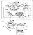
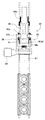
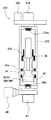
- FIG. 1 is a diagram schematically showing the overall configuration of the automatic analyzer according to the present embodiment
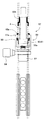
- FIG. 2 is a diagram schematically showing the configuration of the analysis module together with the peripheral configuration of the automatic analyzer.
- the automatic analyzer 100 mounts one or more sample containers 1 (described later) containing biological samples such as blood and urine (hereinafter referred to as samples) arranged at equal intervals in the transport direction.
- a sample rack loading unit 21 for loading a plurality of types (two types in this embodiment) of sample racks 2 and 3 (described later), a transport device 23 for transporting the sample racks 2 and 3 to each part of the automatic analyzer 100, By reading the IDs of the sample racks 2 and 3 (identifier: referred to as sample rack ID) and the IDs of the sample containers 1 mounted in the sample racks 2 and 3 (identifier: referred to as sample ID).
- An ID reading unit 22 to be sent to the overall management computer 28, analysis module analysis modules 24, 25, 26 for analyzing the sample in the sample container 1 transported by the transport device 23, and the analysis module 24
- the entire operation of the automatic analyzer 100 and the sample rack collection unit 27 that collects the sample racks 2 and 3 loaded with the sample containers 1 that have been analyzed in 25 and 26, or the sample racks 2 and 3 that have not been analyzed since then.
- the system includes a general management computer 28 to be controlled and a display device 30 for displaying various setting screens and analysis results in the automatic analyzer 100, and each component is connected via a communication path 106.
- the overall management computer 28 prints information such as a keyboard 102 and a mouse 103 as operating devices for inputting and operating various information, a storage device 107 for storing various information such as analysis instruction information and measurement results, and the like. And a printer 105 for output.
- the analysis modules 24, 25, and 26 are disposed along the transport line 23 and are detachably connected to the transport line 23. That is, the number of analysis modules in the automatic analyzer 100 can be arbitrarily set, and in the present embodiment, a case where three analysis modules (analysis modules 24, 25, 26) are connected is shown.
- the sample container 1 mounted and held in the sample rack 2 or 3 is given a sample ID indicating attribute information (reception number, patient name, requested analysis item, etc.) regarding the sample stored in the sample container 1. Further, the sample racks 2 and 3 are assigned rack IDs having rack identification information such as rack numbers.
- the overall management computer 28 determines which analysis module 24, 25, 26 performs the analysis based on the requested analysis item of the attribute information of the sample container 1, and the transport device 23 determines the determined analysis module
- the sample racks 2 and 3 are transported to 24, 25 and 26, and the analysis operation is performed by the analysis modules 24, 25 and 26.
- the analysis modules 24, 25, 26 are transported by the transport device 23, and are transported in the analysis modules 24, 25, 26, in which the sample racks 2, 3 taken into the analysis modules 24, 25, 26 are transported. Respective analysis modules via an apparatus 119, a reagent disk 111 on which a plurality of reagent bottles 112 containing reagents used for analyzing the sample are mounted, a reaction disk 109 that performs measurement by reacting the sample and the reagent, and an interface 122
- a computer 123 is connected to each component in the 24, 25, 26 and controls the overall operation of each analysis module 24, 25, 26.
- the reaction disk 109 includes a plurality of reaction containers 110 arranged concentrically and a sample in the sample container 1 mounted on the sample racks 2 and 3 that have been transported to the dispensing position of the analytical module transport device 119.
- the computer 123 is connected to the communication path 106 via the interface 122.
- the operator uses the scanning device (keyboard 102, mouse 103) of the overall management computer 28 to set the display device 30 and give an analysis instruction to the automatic analyzer 100.
- the analysis instruction is stored in the storage device 107 and transmitted to each analysis module 24, 25, 26 via the communication path 106.
- Each analysis module 24, 25, 26 controls the analysis module 24, 25, 26 as follows according to the received analysis. That is, the sample dispensing probe 113 dispenses a predetermined amount of the sample contained in the sample container 1 mounted on the sample racks 2 and 3 transported to the dispensing position into the reaction container 110.
- the in-analytical-module transport device 119 removes the sample racks 2 and 3 so that the next sample container 1 is directly under the sample dispensing probe 113 (dispensing position). Moving.
- the sample racks 2 and 3 are carried out by the in-analysis module transport device 119.
- the reaction container 110 into which the sample is dispensed rotates on the reaction disk 109 by the rotation operation of the reaction disk 109. Meanwhile, the reagent in the reagent bottle 112 is dispensed to the specimen in the reaction container 110 by the reagent dispensing probe 118, and the reaction liquid (mixed liquid of specimen and reagent) is stirred by the stirring device 114. 116 and the multiwavelength photometer 117 measure the absorbance of the reaction solution, and then the reaction vessel 110 that has been analyzed is washed by the washing device 115. The measurement signal of the measured absorbance is sent to the computer 123 via the A / D converter 124 and the interface 122.
- various data are calculated based on an analysis method set in advance for each test substance.
- the sample to be analyzed is a standard solution sample
- calibration curve data is calculated from the set concentration data.
- concentration data is calculated from calibration curve data obtained by measuring a standard solution sample.
- 3 to 7 are diagrams schematically showing a sample container and a sample rack used in the present embodiment.
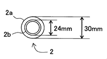
- 3 to 5 are views showing a sample rack on which one sample container is mounted.
- FIG. 3 is a top view
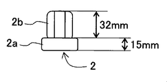
- FIG. 4 is a side view
- FIG. 5 is a side view showing a state in which the sample container is mounted.
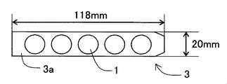
- 6 and 7 are views showing a sample rack on which a plurality of sample containers are arranged at equal intervals in the transport direction
- FIG. 6 is a top view showing a state in which the sample containers are mounted
- FIG. 7 is a sample container. It is a side view which shows a mode that was mounted.
- a sample rack 2 (first sample rack) on which one sample container 1 is mounted is formed to have a smaller diameter (for example, an outer diameter of 30 mm) than a conveyance path (described later) in the conveyance device 23.
- the base 2a is formed with a height of 15 mm, for example, and the sample container holding part 2b is formed with a height of 32 mm above the base 2a. That is, when the sample racks 2 are arranged in contact with the base 2a on the transport path, for example, when four sample racks 2 are arranged, the length is 120 mm, and when five sample racks 2 are arranged, the length is set. 150mm.
- a sample rack 3 (second sample rack) on which a plurality of (five in the present embodiment) sample containers 1 are mounted has a sample container holding portion whose width in the transport direction is the first sample rack 2. It has a sample container holding portion 3b that is narrower than 2b (for example, 20 mm in width) and higher than the upper end portion of the sample container holding portion 2b of the first sample rack 2 (for example, 66 mm in height). .
- FIG. 8 is a top view schematically showing the main configuration of the transport apparatus.
- FIG. 9 is a diagram schematically showing the positional relationship between the transport mechanism and the transport path of the transport device when transporting the first sample rack, and
- FIG. 10 is the case when transporting the second sample rack. It is a figure which shows roughly the positional relationship of the conveyance mechanism and conveyance path of this conveyance apparatus.
- the transport device 23 includes belt conveyors 60 and 61 arranged in tandem along a transport path for transporting the sample holders 2 and 3 on which the sample containers 1 are mounted, and both sides of the belt conveyors 60 and 61.
- the belt conveyors 60 and 61 are driven by a driving mechanism (not shown) so that the sample racks 2 and 3 arranged on the belt conveyors 60 and 61 are transported toward the downstream side of the transport path.
- the transport mechanism 57 grips the sample racks 2 and 3 from both sides in the transport direction at the sample rack gripping position 157 with gripping plates 57a, and transports the sample rack along the transport path.
- a sample rack transport mechanism shaft drive motor 66 that drives the mechanism 59 along the transport path is provided.
- the sample rack gripping mechanism 59 includes two gripping plates 57a, an arm 58 that holds each gripping plate 57a from both sides below, and a direction in which the gripping plate 57a is in an open state (that is, a direction in which the distance between the gripping plates 57a increases).
- a spring 58a for urging the arm 58 and an opening / closing motor 67 for driving the holding plate 57a by driving the arm 58 are provided.
- the opening / closing motor 67 is controlled by the overall management computer 28, and controls the distance between the gripping plates 57a of the sample rack gripping mechanism 59 according to the width of the sample racks 2 and 3.
- the guide members 63 are provided along the transport path on both sides of the transport path, and guide the movement of the first sample rack 2 in the transport direction while restricting the movement of the sample container holder 2b in the width direction.
- the guide member 63a and the upper direction of the sample container holding part 2b of the first sample rack 2 are provided along the transfer path on both sides of the transfer path and in the width direction of the sample container holding part 3a of the second sample rack 3
- a second guide member 63b that guides the movement in the transport direction while restricting the movement to the position.
- a configuration having two-stage guides that is, an upper guide (second guide member 63b) and a lower guide (first guide member 63a) is shown.
- a plurality of guides of three or more stages may be provided in accordance with the shape of the symmetric sample rack, and the guide function of the sample rack may be further improved.
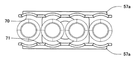
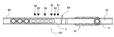
- FIG. 11 to 13 are diagrams showing the configuration of the gripping plate of the transport mechanism.
- FIG. 11 shows the open state of the gripping plate of the transport mechanism
- FIG. 12 shows the closed state of gripping the first sample rack.
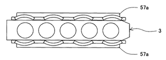
- 13 is a diagram showing a closed state in which the second sample rack is held.
- the opposing surfaces of the gripping plate 57a are formed along the side surface shape of the base portion 2a of the first sample rack 2, and are provided with curved surface portions 70 arranged at equal intervals in the transport direction, and A flat surface portion 71 is provided that is formed along the side surface shape of the two-sample rack 3 and disposed between the curved surface portions in the transport direction.
- the length of the gripping plate 57a in the transport direction is configured to be approximately the same as the length of the narrow sample rack (in the present embodiment, the second sample rack 3) in the transport direction.
- the gripping plate 57a of the transport mechanism 57 When the gripping plate 57a of the transport mechanism 57 is changed from the open state (see FIG. 11) in which the sample racks 2 and 3 are released to the closed state, the first sample rack 2 is gripped by the gripping plate 57a.
- the side surfaces of the second base portion 2a are sandwiched and held stably by the curved surface portions 70 of the grip plates 57a on both sides of the conveyance path (see FIG. 12).
- the gripping plate 57a of the transport mechanism 57 When the gripping plate 57a of the transport mechanism 57 is changed from the open state (see FIG. 11) in which the sample racks 2 and 3 are released to the closed state, the second sample rack 3 is gripped by the gripping plate 57a.
- the side surfaces of the sample rack 3 are sandwiched by the flat portions 71 of the grip plates 57a on both sides of the transport path and are stably held.
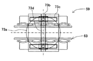
- FIG. 14 to 16 are diagrams showing the opening / closing structure of the gripping plate 57a in the opening / closing motor 67 of the sample rack gripping mechanism 59.
- FIG. 14 shows the open state of the gripping plate 57a
- FIG. 15 shows the gripping of the first sample rack.
- FIG. 16 is a diagram illustrating the closed state
- FIG. 16 is a diagram illustrating the closed state in which the second sample rack is held.
- the opening / closing mechanism of the sample rack gripping mechanism 59 includes a disk-shaped member 73a that is rotationally driven in the horizontal direction by the opening / closing motor 67 about the center in the transport direction and the width direction in the transport path of the grip plate 57a, and a disk-shaped member.
- a sliding projection 73b provided on the surface on the gripping plate 57a side at two positions that are symmetrical with respect to the center of 73a, and a gripping plate 57a that is provided along the transport path in the transporting direction of the sliding projection 73b.
- a vertical guide 73c for guiding the movement of the grip plate 57 and a lateral guide 73d for guiding the movement of the gripping plate 57a in the width direction in the conveyance path.
- the disk-shaped member 73a is rotationally driven by the opening / closing motor 67, and the width direction of the sliding projection 73b in the transport path is increased.
- the gripping plate 57a having the longitudinal guide 73c that guides the movement of the sliding protrusion 73b is moved in the width direction in the transport path while being guided by the lateral guide 73d. 2 and the second sample rack 3 are held by the holding plate 57a (see FIGS. 15 and 16). That is, by changing the rotation direction of the opening / closing motor 67, the holding plate 57a can be driven to open / close. Further, the distance (opening / closing distance) between the gripping plates 57a can be controlled by changing the rotation angle of the disk-shaped member 73a by the opening / closing motor 67.
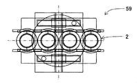
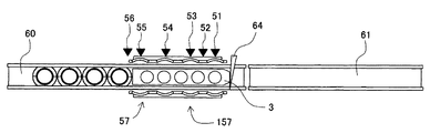
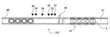
- FIG. 17 and 18 are diagrams showing the positional relationship between each sensor and the sample rack at the sample rack holding position.
- FIG. 17 shows an example in which four first sample racks are stopped at the sample rack holding position by the rack stopper.
- FIG. 18 is a diagram showing an example in which the second sample rack is stopped.
- the sensors 51 to 56 are arranged in order from the downstream side of the transport path, the center position of the first first sample rack 2 (sensor 51), and the first and second first sample racks. 2 (sensor 52), the center position of the second first sample rack 2 (sensor 53), the center position of the third first sample rack 2 (sensor 54), and the fourth first sample rack 2 Are arranged so as to detect the presence or absence of the sample racks 2 and 3 at the center position (sensor 55) and the upstream end position (sensor 56) of the fourth first sample rack 2.
- the output signal (sample rack presence / absence information) is turned ON when the sample racks 2 and 3 are detected at the respective positions, and the output signal (sample rack presence / absence information) is turned OFF when not detected. .
- the output signals obtained from the sensors 51 and 52 are ON and ON, respectively, and are obtained from the sensors 55 and 56. Information to be turned ON and ON, respectively.
- the sample rack presence / absence information obtained from the sensors 51 to 56 makes it possible to determine which of the sample racks 2 and 3 at the sample rack holding position 157, and thus, a plurality of types of sample racks having different widths. Can be determined.
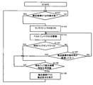
- FIG. 19 to 21 are flowcharts showing the flow of the sample rack transport process by the transport device
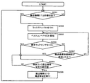
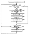
- FIG. 19 is a flowchart showing the sample rack transport request process of the transport process
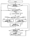
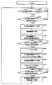
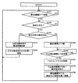
- FIG. 20 is the sample rack transfer process of the transport process
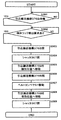
- FIG. 21 is a flowchart showing the sample dispensing process of the transport process.
- the overall management computer 28 first determines whether or not the transport mechanism 57 is in a standby state (not driven) (step S1101). If the determination result is NO, the determination in step S1101 is repeated until the determination result is YES. If the determination result in step S1101 is YES, the rack stopper 64 is turned on to block the movement of the sample racks 2 and 3 on the belt conveyor 60 (step S1102), and the belt conveyor 60 is driven (step S1103). . Subsequently, it is determined whether or not the sensor 51 is ON (step S1104). If the determination result is NO, it is determined whether or not a predetermined transport mechanism standby time has elapsed (step S1107).
- step S1107 determines whether the transport mechanism 57 is waiting at the sample rack gripping position 157 (step S1104). If the determination result in step S1105 is YES, a sample rack transport request for transporting the sample racks 2 and 3 at the sample rack gripping position 157 is issued to the transport mechanism 57 (step S1106), and then in step S1101 Return to processing. If the determination result in step S1106 is NO, the determination in step S1106 is repeated until the determination result is YES.
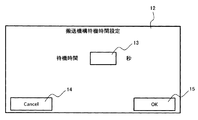
- FIG. 22 is a diagram showing a setting screen for setting the transport mechanism standby time in the sample rack transport request process.
- the transport mechanism standby time setting screen 12 is displayed on the display device 30 and is set by an operation using the operation device (keyboard 102, mouse 103).
- the standby time input unit 13 cancels input.
- a button 14 and an OK button 15 for determining an input result are provided.
- the waiting time of the transport mechanism 57 is input to the input unit 12 by the operating device, and is determined by operating the OK button 15.
- the overall management computer 28 first determines whether or not the transport mechanism 57 is waiting at the sample rack gripping position 157 (step S1301), and the determination result. If YES, it is determined whether a sample rack transport request has been issued in the sample rack transport request process (step S1302). If the determination result in step S1302 is NO, the determination in step S1301 is repeated. If the determination result is YES, the rack stopper 64 is turned off and the movement of the sample racks 2 and 3 on the belt conveyor 60 is released.
- step S1304 Whether the sample rack at the sample rack holding position 157 is the sample rack 2 (first sample rack) on which one sample container 1 is mounted, or the sample rack 3 (first sample rack) on which a plurality (five) sample containers 1 are mounted. It is determined whether it is a two-sample rack) (step S1304). If the determination result in step S1304 is the first sample rack 2, the distance between the grip plates 57a of the transport mechanism 57 is closed so as to be the width of the first sample rack 2 (step S1305), and the transport mechanism 57 is closed. After moving to the sample dispensing position 162 (step S1307), the process returns to step S1301.
- step S1304 determines whether the determination result in step S1304 is the second sample rack 3
- the distance between the gripping plates 57a of the transport mechanism 57 is closed so as to be the width of the second sample rack 3 (step S1306), and transport is performed.
- the mechanism 57 is moved to the sample dispensing position 162 (step S1307), and then the process returns to step S1301. If the determination result in step S1301 is NO, it is determined whether the transport mechanism 57 is waiting at the sample dispensing position 162 (step S1308). If the determination result is YES, the transport mechanism 57 is determined.
- a sample dispensing schedule is created, and the process returns to the determination in step S1301. If the determination result in step S1308 is NO, the process returns to the determination in step S1301.
- the overall management computer 28 first completes the dispensing of the sample in the sample container 1 mounted in the sample racks 2 and 3 at the sample dispensing position 162. If the determination result is NO, the process of step S1401 is repeated until the determination result is YES. If the determination result in step S1401 is YES, it is determined whether there is a sample to be dispensed in the other sample containers 1 mounted in the sample racks 2 and 3 (step S1402).
- step S1403 If YES, the sample container 1 to be dispensed is moved to the dispensing position (step S1403), the transport mechanism 57 is opened (step S1404), the rack stopper 65 is turned on, and the sample rack 2, 3 is cut off (step S1405), and only the sample racks 2 and 3 loaded with the sample containers 1 that have been dispensed by driving the belt conveyor 61 are released from the transport mechanism 57 to the next analysis module. Transport is performed (step S1406), the rack stopper 65 is turned OFF to open the transport path (step S1407), and the transport mechanism 57 is closed (step S1). 08), then returns to the determination of step S1401.
- step S1402 If the determination result in step S1402 is NO, the transport mechanism 57 is opened (step S1409), the belt conveyor 61 is driven (step S1410), and the transport mechanism 57 is moved to the sample rack gripping position 157. (Step S1411) Then, it returns to determination of step S1401.
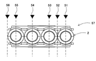
- FIGS. FIG. 23 to FIG. 30 are diagrams schematically showing how the sample racks 2 and 3 are gripped and transported at the sample rack gripping position 157.
- FIG. 23 is a diagram showing a state in which four or more sample racks 2 (first sample racks) on which one sample container 1 is mounted are continuously stopped by the rack stopper 64 at the sample rack holding position 157.
- FIG. FIG. 6 is a diagram showing a state in which four downstream first sample racks 2 are gripped by the transport mechanism 57 and transported downstream.
- sample rack presence / absence information obtained from the sensors 51 and 52 are respectively.
- the output signals (sample rack presence / absence information) obtained from the sensors 55 and 56 are ON and OFF, respectively.
- the rack stopper 64 is driven to turn OFF, the belt conveyor 60 is released, and only the four sample racks 2 gripped by the transport mechanism 57 are transported on the belt conveyor 61 on the downstream side.
- the belt stopper 60 is again shut off by the rack stopper 64 and the belt conveyor 60 is operated again, so that the subsequent sample rack 2 located upstream of the sample rack gripping position 157 is stopped, Can be transported by movement.
- FIG. 25 is a diagram showing a state in which a plurality of sample racks 3 (second sample racks) on which a plurality (five) of sample containers 1 are mounted are stopped by a rack stopper 64 at a sample rack gripping position 157.
- FIG. 6 is a diagram showing a state in which the second sample rack 3 is gripped by the transport mechanism 57 and transported downstream.
- sample rack presence / absence information obtained from the sensors 51 and 52 are ON
- the output signals (sample rack presence / absence information) obtained from the sensors 55 and 56 are ON and ON, respectively.
- the sample rack stopped at the sample rack holding position 157 is the sample rack 3 (second sample rack), and between the holding plates 57a of the transport mechanism 57 according to the width of the sample rack 3.
- the sample rack 3 is gripped by determining the grip width and setting the grip width.
- the rack stopper 64 is driven to be turned OFF, the belt conveyor 60 is released, and the sample rack 3 gripped by the transport mechanism 57 is transported on the belt conveyor 61 on the downstream side.
- the belt stopper 60 is again shut off by the rack stopper 64 and the belt conveyor 60 is operated again, so that the subsequent sample rack 3 located on the upstream side of the sample rack gripping position 157 is stopped. Can be transported by movement.
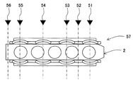
- the sample rack holding position 157 includes the sample rack 2 (first sample rack) on which one sample container 1 is mounted and the sample rack 3 (second sample rack) on which a plurality (five) of sample containers 1 are mounted.
- FIG. 28 is a diagram illustrating a state in which only the most downstream first sample rack 2 is gripped by the transport mechanism 57 and transported to the downstream side.
- sample rack presence / absence information obtained from the above are ON and OFF, respectively, and the output signals (sample rack presence / absence information) obtained from the sensors 55 and 56 are ON and ON, respectively.
- the sample rack stopped at the most downstream side of the sample rack gripping position 157 is the sample rack 2 (first sample rack) and the second sample rack follows, and the sample rack
- the grip width between the grip plates 57a of the transport mechanism 57 is determined in accordance with the width of 2, and the sample rack 2 is gripped by making it closed.
- the rack stopper 64 is driven to turn OFF, the belt conveyor 60 is released, and only the top sample rack 2 gripped by the transport mechanism 57 is transported on the belt conveyor 61 on the downstream side.
- the second sample rack that is narrower than the first sample rack remains in place.
- the belt stopper 60 is again shut off by the rack stopper 64 and the belt conveyor 60 is operated again, so that the subsequent sample rack 3 located on the upstream side of the sample rack gripping position 157 is stopped. Can be transported by movement.
- the width of the transport mechanism 57 the same as the width of the number of sample racks that can be gripped, only the sample rack that can be gripped by the sample rack transport mechanism 57 can be moved and cannot be gripped.
- the sample rack can be left on the belt conveyor 60.
- FIG. 29 shows a sample rack holding position 157 in which a sample rack 3 (second sample rack) on which a plurality (five) of sample containers 1 are mounted and a sample rack 2 (first sample rack) on which one sample container 1 is mounted.
- FIG. 30 is a diagram showing a state in which only the most downstream second sample rack 3 is gripped by the transport mechanism 57 and transported to the downstream side.
- sample rack 3 second sample rack
- sample rack 2 first sample rack
- the output signals are ON and ON, respectively
- the output signals (sample rack presence / absence information) obtained from the sensors 55 and 56 are ON and ON, respectively.
- the sample rack stopped at the most downstream side of the sample rack holding position 157 is the sample rack 3 (second sample rack)
- the holding plate of the transport mechanism 57 is matched to the width of the sample rack 3.
- the sample rack 3 is gripped by determining the grip width between 57a and setting it to the closed state.
- the rack stopper 64 is driven to turn OFF, the belt conveyor 60 is released, and only the sample rack 3 gripped by the transport mechanism 57 is transported on the downstream belt conveyor 61 and transported. The subsequent first sample rack that is not gripped by the plate 57a remains in place.
- the belt stopper 60 is again shut off by the rack stopper 64 and the belt conveyor 60 is operated again, so that the subsequent sample rack 3 located on the upstream side of the sample rack gripping position 157 is stopped. Can be transported by movement.
- one or a plurality of sample containers may be mounted on a sample rack and transported.
- a transport line is required for each (shape)
- the structure and control of the automatic analyzer are complicated, leading to an increase in the size and cost of the device.
- the sample racks 2 and 3 on the transport path through which the sample racks 2 and 3 are transported are gripped by gripping plates 57a from both sides in the transport direction, and along the transport path. Since it is configured to be transported, a plurality of types of sample racks can be transported while suppressing an increase in size and cost of the apparatus.
- FIG. 31 to FIG. 33 are diagrams showing the configuration of the gripping plate of the transport mechanism in this modification.
- FIG. 31 shows the open state of the gripping plate of the transport mechanism
- FIG. 32 shows the closed state that grips the first sample rack.
- FIG. 33 is a diagram showing a closed state in which the second sample rack is held.
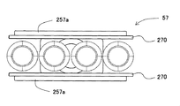
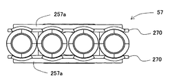
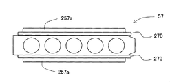
- an elastic body that is deformed in accordance with the shape of the side surface of the first sample rack 2 or the second sample rack 3 is disposed on the opposing surface of the gripping plate 257a in this modification.
- the length of the gripping plate 257a in the transport direction is configured to be substantially the same as the length of the narrow sample rack (second sample rack 3 in the present embodiment) in the transport direction.
- FIGS. 31 and 32 in the open state (see FIG. 31) in which the grip plate 257a of the transport mechanism 57 releases the sample racks 2 and 3, the opposing surfaces of the grip plate 257a are flat, but are closed.
- FIG. 32 when the first sample rack 2 is gripped by the gripping plate 257a, the shape of the gripping plate 257a is deformed into a curved surface in accordance with the shape of the side surface of the base 2a of the first sample rack 2. Thus, the first sample rack 2 is sandwiched, and the first sample rack 2 is stably held.
- FIG. 33 when the second sample rack 3 is gripped by the gripping plate 257a from the open state (see FIG. 31) to the closed state (see FIG. 33), the second sample rack 3 The side surface is sandwiched by the flat grip plate 257a and stably held.
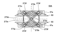
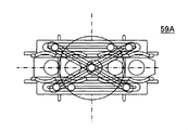
- FIG. 34 to 36 are diagrams showing the opening / closing structure of the gripping plate 57a in the opening / closing motor 67 of the sample rack gripping mechanism 59 in this modification, FIG. 34 shows the open state of the gripping plate 57a, and FIG. 35 shows the first sample.
- FIG. 36 is a diagram illustrating a closed state in which the rack is gripped, and FIG. 36 is a diagram illustrating a closed state in which the second sample rack is gripped.
- the open / close mechanism of the sample rack gripping mechanism 59A in the present modification includes a disk-shaped member 273a that is rotationally driven in the horizontal direction by the open / close motor 67 about the center in the transport direction and the width direction in the transport path of the grip plate 57a, A sliding protrusion 273b provided on the surface on the gripping plate 57a side at two positions that are point-symmetric at the center of the disk-shaped member 73a, and a sliding protrusion 273b provided on the gripping plate 57a along the conveyance path.
- the two rod-shaped members 273g having the same length are arranged so as to intersect at the center 273e of the disk-shaped member 273a at the center, and the longitudinal guides 273c of the gripping plate 57a are disposed at both ends.
- a sliding protrusion 273f is provided to move along.
- the disk-shaped member 273a is rotationally driven by the opening / closing motor 67, and the width direction of the sliding projection 273b in the transport path is increased.
- the gripping plate 57a having the longitudinal guide 273c that guides the movement of the sliding protrusion 273b is moved in the width direction in the transport path while being guided by the lateral guide 273d. 2 and the second sample rack 3 are held by the holding plate 57a (see FIGS. 35 and 36).
- the parallelism of the holding plate 57a is maintained by the two rod-like members 273g.
- the holding plate 57a can be driven to open / close. Further, by changing the rotation angle of the disk-shaped member 273a by the opening / closing motor 67, the distance (opening / closing distance) between the gripping plates 57a can be controlled.
- FIG. 1 is a diagram schematically showing the overall configuration of the automatic analyzer according to the present embodiment
- FIG. 2 is a diagram schematically showing the configuration of the analysis module together with the peripheral configuration of the automatic analyzer.
- FIG. 37 is a top view schematically showing the main configuration of the transport apparatus in the present embodiment.
- FIG. 38 is a diagram schematically showing the configuration of the transport mechanism of the transport apparatus when transporting the first sample rack
- FIG. 39 is the transport of the transport apparatus when transporting the second sample rack. It is a figure which shows the structure of a mechanism roughly.
- the transport device 323 in the present embodiment includes belt conveyors 60 and 61 arranged in tandem along a transport path for transporting the sample holders 2 and 3 on which the sample containers 1 are mounted, and a belt conveyor.
- the sample rack transport path 360 connected in cascade between 60 and 61, the rack stopper 64 provided at the sample rack gripping position 157 disposed on the belt conveyor 60, and the sample racks 2 and 3 in the sample rack gripping maintenance 157
- a plurality of sensors 51 to 56 for detecting the presence or absence of the sample a transport mechanism 57 for gripping the sample racks 2 and 3 at the sample rack gripping position 157 and transporting them along the sample rack transport path 363, and along the sample rack transport path 360
- Dispensing probe 362 for dispensing a sample from the rack, rack stopper 459, and pull-in Mechanism 376A, a shutter 366 and 367 for closing the conveying path of the sample rack 2 by 376B, is schematically a transport mechanism 377 Metropolitan transporting a sample rack 2 and 3 along the belt conveyor 368, 369.
- the belt conveyors 60, 61, 368, 369 are driven by a driving mechanism (not shown) so that the sample racks 2, 3 arranged on the belt conveyors 60, 61 are transported toward the downstream side of the transport path.
- the transport mechanisms 57 and 377 hold the sample racks 2 and 3 at the sample rack gripping position 157 sandwiched by gripping plates 57a from both sides in the transport direction, and transport the sample racks along the transport path.
- a sample rack transport mechanism shaft drive motor 66 that drives the rack gripping mechanism 59 along the transport path is provided.
- the sample rack gripping mechanism 59 includes two gripping plates 57a, an arm 58 that holds each gripping plate 57a from both sides below, and a direction in which the gripping plate 57a is in an open state (that is, a direction in which the distance between the gripping plates 57a increases).
- a spring 58a for urging the arm 58 and an opening / closing motor 67 for driving the holding plate 57a by driving the arm 58 are provided.
- the opening / closing motor 67 is controlled by the overall management computer 28, and controls the distance between the gripping plates 57a of the sample rack gripping mechanism 59 according to the width of the sample racks 2 and 3.
- the pull-in transport mechanisms 376A and 376B grip the sample racks 2 and 3 from both sides in the transport direction with the grip plates 357a, and transport the sample rack grip mechanism 359 and the sample rack grip mechanism 359 along the transport path.
- a sample rack transport mechanism shaft drive motor 380 that drives in the direction along the transport path and in the width direction is provided.
- the sample rack gripping mechanism 359 includes two gripping plates 357a, arms 376 that hold the gripping plates 357a from both upper sides, and a direction in which the gripping plates 357a are in an open state (that is, a direction in which the distance between the gripping plates 357a increases). And a spring 376a for urging the arm 376 and an opening / closing motor 380 for driving the holding plate 357a by driving the arm 376.
- the open / close motor 380 is controlled by the overall management computer 28 and controls the distance between the grip plates 357 a of the sample rack gripping mechanism 359 according to the width of the sample racks 2 and 3.
- the guide members 63 and 363 are provided along the transport path on both sides of the transport path, and guide the movement of the first sample rack 2 in the transport direction while restricting the movement of the sample container holder 2b in the width direction.
- One guide member 63a and the upper side of the sample container holding part 2b of the first sample rack 2 are provided along the transfer path on both sides of the transfer path, and the sample container holding part 3a of the second sample rack 3
- the second guide member 63b guides the movement in the transport direction while restricting the movement in the width direction.
- a configuration having two-stage guides that is, an upper guide (second guide member 63b) and a lower guide (first guide member 63a) is shown.
- a plurality of guides of three or more stages may be provided in accordance with the shape of the symmetric sample rack, and the guide function of the sample rack may be further improved.
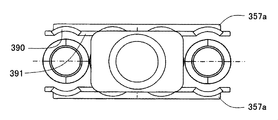
- FIG. 40 and 41 are diagrams showing the configuration of the gripping plate of the pull-in transport mechanism.
- FIG. 40 shows the open state of the gripping plate of the transport mechanism
- FIG. 41 shows the closed state of gripping the first sample rack.
- the gripping plate 357a has substantially the same configuration as the gripping plate 57a, and the sample container holding portion 2b of the first sample rack 2 is disposed on the opposite surface of the gripping plate 357a.
- the curved surface portion 390 is formed along the side surface shape of the second sample rack 3 and is disposed between the curved surface portion in the transport direction.
- a flat portion 391 is provided.
- the length of the gripping plate 357a in the transport direction is configured to be substantially the same as the length of the narrow sample rack (in this embodiment, the second sample rack 3) in the transport direction.
- the gripping plate 357a of the pull-in transport mechanism 357 When the gripping plate 357a of the pull-in transport mechanism 357 is closed from the open state (see FIG. 40) in which the sample racks 2 and 3 are released, the first sample rack 2 is gripped by the gripping plate 357a.
- the side surface of the sample container holding part 2b of the rack 2 is sandwiched and held stably by the curved surface parts 390 of the grip plates 357a on both sides of the transport path (see FIG. 41).
- the gripping plate 357a of the pull-in transport mechanism 357 is closed from the open state (see FIG. 40) in which the sample racks 2 and 3 are released, whereby the second sample rack 3 is gripped by the gripping plate 357a.
- the side surface of the second sample rack 3 is sandwiched by the flat portions 391 of the grip plates 357a on both sides of the transport path and is stably held.
- FIG. 42 is a flowchart schematically showing the sample rack transport request process of the transport process.
- the overall management computer 28 first determines whether or not the transport mechanism 57 is in a standby state (not driven) (step S2001). If the determination result is NO, the determination in step S2001 is repeated until the determination result is YES. If the determination result in step S2001 is YES, the rack stopper 64 is turned on to block the movement of the sample racks 2 and 3 on the belt conveyor 60 (step S2002), and the belt conveyor 60 is driven (step S2003). . Subsequently, it is determined whether or not the sensor 51 is ON (step S2004). If the determination result is NO, it is determined whether or not a predetermined transport mechanism standby time has elapsed (step S2007).
- step S2007 If the determination result in step S2007 is NO, the process returns to step S2003. If the determination result in step S2004 is YES, or if the determination result in step S2007 is YES, it is determined whether the transport mechanism 57 is waiting at the sample rack gripping position 157 (step S2004). If the determination result in step S2005 is YES, a sample rack transport request for transporting the sample racks 2 and 3 at the sample rack gripping position 157 is issued to the transport mechanism 57 (step S2006), and then in step S2001. Return to processing. If the determination result in step S2006 is NO, the determination in step S2006 is repeated until the determination result is YES.
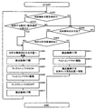
- FIG. 43 is a flowchart schematically showing the transfer mechanism moving process of the transfer process.
- the overall management computer 28 first determines whether or not the transport mechanism 57 is waiting at the receiving position of the sample racks 2 and 3 (step S2301). If the determination result is YES, the rack stopper 64 is turned off (step S2302), the transport mechanism 57 is closed, and the sample racks 2 and 3 are held (step S2303). Subsequently, it is determined whether or not the pull-in transport mechanism 376A is on standby (step S2304). If the determination result is NO, the process waits until the determination result is YES. If the determination result is YES, the transport mechanism 57 is determined.
- step S2305 a movement request for the drawing conveyance mechanism 376A is issued (step S2306), and the process returns to step S2301.
- step S2301 determines whether or not the transport mechanism 57 is waiting at the retracted position (step S2307), and a request for movement of the transport mechanism 57 to the receiving position is issued. It is determined whether or not (step S2308). If any of the determination results in steps S2307 and S2308 is NO, the process returns to step S2301, and if both determination results in steps S2307 and S2308 are YES, the transport mechanism 57 is moved to the receiving position ( Step S2309) and the process returns to step S2301.
- FIG. 44 is a flowchart schematically showing the pull-in transport mechanism moving process of the transport process.
- the overall management computer 28 first determines whether or not the pull-in transport mechanism 376A is on standby (step S2401) and operates the pull-in transport mechanism 376A. It is determined whether a request has been issued (step S2402). When the determination result of any of steps S2401 and S2402 is NO, the processes of steps S2401 and S2402 are repeated until both determination results are YES. If both the determination results in steps S2401 and S2402 are YES, the pull-in conveyance mechanism 376A is closed (step S2403), the conveyance mechanism 57 is opened (step S2404), and the conveyance mechanism 57 is requested to move to the receiving position. Issue (step S2405).
- step S2406 it is determined whether or not the transport mechanism 57 is in a standby state at the receiving position. If the determination result is NO, the process of step S2406 is repeated. If the decision result in the step S2406 is YES, the shutter 366 is opened (step S2407), the drawing / conveying mechanism 376A is moved to the belt conveyor 368 (step S2408), the drawing / conveying mechanism 376A is opened (step S2409), An operation request for the conveyor 368 is issued (step S2410). Subsequently, it is determined whether or not a request for movement of the pull-in transport mechanism 376A to the receiving position has been issued (step S2411). If the determination result is NO, the determination process of step S2411 is repeated. If the decision result in the step S2411 is YES, the drawing transport mechanism 376A is moved to the standby position (step S2412), and the process returns to the step S2401.
- FIG. 45 is a flowchart schematically showing the belt conveyor driving process of the conveying process.
- the overall management computer 28 first determines whether or not an operation request for the pull-in transfer mechanism 376A has been issued (step S2501). If NO, the process of step S2501 is repeated. If the determination result in step S2501 is YES, the rack stopper 372 is opened and the rack stopper 373 is closed (step S2502). Subsequently, the belt conveyor 368 is driven (step S2503), and the sample identifier (sample ID) of the sample container 1 is read (step S2504). Next, it is determined whether or not the transport mechanism 377 is waiting at the sample dispensing position 362a (step S2505). If the determination result is NO, the process of step S2505 is repeated.
- step S2505 If the determination result in step S2505 is YES, the rack stoppers 373 and 374 are opened, the rack stopper 375 is closed (step S2507), and the belt conveyor 368 is driven (step S2508). Subsequently, it is determined whether or not all the sample racks 2 and 3 of the pull-in transport mechanism 376A have been carried out (step S2508). If the determination result is NO, the process returns to step S2502. If the determination result in step S2508 is YES, a request for movement to the receiving position is issued to the pull-in conveyance mechanism 376A (step S2509), a movement request is issued to the conveyance mechanism 377 (step S2510), and step S2502 is performed. Return to the process.
- FIG. 46 is a flowchart schematically showing the belt conveyor driving process of the conveying process.
- the overall management computer 28 first determines whether or not the transfer mechanism 377 is waiting at the delivery position (step S2601), and the determination result is YES. In this case, it is determined whether an operation request for the belt conveyor 368 has been issued (step S2602). If the determination result in step S2602 is NO, the process of step S2602 is repeated. If the determination result in step S2602 is YES, the rack stopper 375 is opened (step S2603), the transport mechanism 377 is closed (step S2604), moved to the sample dispensing position 362a (step S2605), and step S2601. Return to the process.
- step S2601 determines whether the transport mechanism 377 is waiting at the dispensing position. If the determination result is NO, the process of step S2601 is performed. Return. If the determination result in step S2606 is YES, a sample dispensing position schedule is created (step S2607), and the process returns to step S2601.
- FIG. 47 is a flowchart schematically showing the transport mechanism driving process at the dispensing position of the transport process.
- step S2701 the overall management computer 28 first determines whether or not the transport mechanism 377 is in a standby state (step S2701), and the determination result is If NO, the process of step S2701 is repeated. If the determination result in step S2701 is YES, it is determined whether the sample dispensing process for the sample container 1 is completed (step S2702). If the determination result is NO, the process in step S2702 is performed. repeat. If the determination result in step S2702 is YES, it is determined whether there is another sample to be dispensed (that is, the sample to be analyzed) (step S2703).
- Step S2714 the movement distance is calculated according to the sample container fixed by the transport mechanism 377 (step S2714), and the sample container 1 containing the sample to be analyzed is moved to the dispensing position 362a according to the calculation result at step S2714.
- Step S2704 the process returns to step S2701. If the determination result in step S2703 is NO, the transport mechanism 57 is opened (step S2705), and it is determined whether the pull-in transport mechanism 376B is in a standby state (step S2706). If the determination result in step S2706 is NO, the process of step S2706 is repeated.
- step S2706 If the determination result in step S2706 is YES, the belt conveyor 369 is driven (step 2707), an operation request for the pull-in transport mechanism 376B is issued (step S2708), and the transport mechanism 377 is moved to the sample racks 2 and 3. (Step S2709), the process returns to step S2701.
- FIG. 48 is a flowchart schematically showing the pull-in transport mechanism driving process of the transport process.
- the overall management computer 28 first determines whether or not the pull-in transport mechanism 376B is in a standby state (step S2801), and the determination result is NO. In that case, the process of step S2801 is repeated. If the determination result in step S2801 is YES, it is determined whether a request to carry out sample racks 2 and 3 is issued (step S2802). If the determination result is NO, the process of step S202 is performed. repeat.
- step S2803 If the determination result in step S2802 is YES, the pull-in transport mechanism 376B is closed (step S2803), the shutter 367 is opened (step S2804), and the pull-in transport mechanism 376B is moved to the unloading position (step S2805).
- the pull-in transport mechanism 376B is opened (step S2806), the belt conveyor 61 is driven to transport the sample rack to the next analysis module (step S2807), the pull-in transport mechanism 376B is moved to the receiving position (step S2808), and the shutter 367. Is closed (step S2809), and the process is terminated.
- steps S2802 and S2803 the operation request received from the belt conveyor 61 is received together with information for determining the shape of the sample rack, the grip width is determined according to the shape of the sample rack, and the sample rack is fixed by closing. To do.
- FIG. 49 is a flowchart schematically showing the analysis processing.
- the overall management computer 28 first determines whether or not the sample to be analyzed is an emergency sample (step S2901). It is determined whether or not the note has been completed (step S2903). If the determination result of step S2903 is NO, the process of step S2903 is repeated. If the determination result in step S2903 is YES, it is determined whether there is another sample to be analyzed (step S2904). If the determination result is YES, the sample to be analyzed is dispensed.
- Step S2905 the transport mechanism 57 is opened (step S2906), the rack stopper 459 is turned ON (step S2907), the belt conveyor 61 is driven (step S2908), and the rack stopper 459 is turned OFF (step S2909). Then, the transport mechanism 57 is closed (step S2910), and the process returns to step S2901. If the determination result in step S2904 is NO, the transport mechanism 57 is opened (step S2911), the belt conveyor 61 is driven (step S2912), and the transport mechanism 57 is moved to the sample rack receiving position. (Step S2913), the process ends. If the determination result in step S2901 is NO, it is determined whether there is a subsequent emergency sample (step S2902). If the determination result is YES, the process proceeds to step S2905, where the determination result is If NO, the process proceeds to step S2903.
- This modification shows a case where the transport direction of the sample racks 2 and 3 is changed by the pull-in transport mechanism 476.
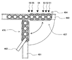
- FIG. 50 is a diagram schematically showing the configuration of the transport apparatus at the retracted position of the sample rack.
- members similar to those of the second embodiment are denoted by the same reference numerals, and description thereof is omitted.
- the sample racks 2 and 3 provided on the belt conveyor 460 are retracted at a position 457 at which the sample racks 2 and 3 block the movement of the sample racks 2 and 3 and the sample rack 2 in a direction different from the belt conveyor 460.
- the pull-in transport mechanism 476 for transporting the sample racks 2 and 3 from the belt conveyor 460 to the belt conveyor 461, and the samples in the sample containers 1 of the sample racks 2 and 3 on the belt conveyor 461.
- a dispensing probe 462 to be poured and sensors 51 to 56 are arranged.
- Sample container 2 Sample rack (first sample rack) 3 Sample rack (second sample rack) 21 Sample rack loading unit 22 ID reading unit 23 Transport device 24, 25, 26 Analysis module 27 Sample rack recovery unit 28 Overall management computer 30 Display device 57, 377 Transport mechanism 57a, 257a Grip plate 376A, 376B, 476 Pull-in transport mechanism 60 , 61, 368, 369 Belt conveyor 62, 362 Dispensing probe 100 Automatic analyzer
Abstract
Description
本発明の第1の実施の形態を図1~図30を参照しつつ説明する。 <First Embodiment>
A first embodiment of the present invention will be described with reference to FIGS.
本発明の第1の実施の形態の変形例を図31~図33を参照しつつ説明する。 <Modification of the first embodiment>
A modification of the first embodiment of the present invention will be described with reference to FIGS.
本発明の第1の実施の形態のその他の変形例を図34~図36を参照しつつ説明する。 <Other Modifications of First Embodiment>
Another modification of the first embodiment of the present invention will be described with reference to FIGS.
本発明の第2の実施の形態を図37~図49を参照しつつ説明する。図中、第1の実施の形態と同様の部材には同じ符号を付し、説明を省略する。 <Second Embodiment>
A second embodiment of the present invention will be described with reference to FIGS. In the figure, the same members as those in the first embodiment are denoted by the same reference numerals, and description thereof is omitted.
本発明の第2の実施の形態の変形例を図50を参照しつつ説明する。 <Modification of Second Embodiment>
A modification of the second embodiment of the present invention will be described with reference to FIG.
2 検体ラック(第1検体ラック)
3 検体ラック(第2検体ラック)
21 検体ラック投入部
22 ID読取部
23 搬送装置
24,25,26 分析モジュール
27 検体ラック回収部
28 全体管理コンピュータ
30 表示装置
57,377 搬送機構
57a,257a 把持板
376A,376B,476 引込搬送機構
60,61,368,369 ベルトコンベヤ
62,362 分注プローブ
100 自動分析装置 1
3 Sample rack (second sample rack)
21 Sample
Claims (13)
- 分析対象の検体を収容した1つ以上の検体容器を搬送方向に等間隔に並べて搭載する検体ラックを搬送する搬送装置と、前記検体容器に収容された検体の分析を行う分析部とを有する自動分析装置において、
前記搬送装置は、
前記検体ラックが搬送される第1の搬送路上の前記検体ラックを搬送方向側方の両側から把持板で挟んで把持し、前記第1の搬送路に沿って搬送する検体ラック把持機構と、
前記検体ラックの幅に応じて、前記検体ラック把持機構の把持板間の距離を制御する把持幅制御部と
を備えたことを特徴とする自動分析装置。 Automatic having a transport device for transporting a sample rack in which one or more sample containers containing samples to be analyzed are arranged at equal intervals in the transport direction, and an analysis unit for analyzing the samples stored in the sample containers In the analyzer
The transfer device
A sample rack gripping mechanism for gripping the sample rack on the first transport path through which the sample rack is transported by sandwiching it with grip plates from both sides in the transport direction, and transporting the sample rack along the first transport path;
An automatic analyzer comprising: a grip width control unit that controls a distance between grip plates of the sample rack gripping mechanism according to the width of the sample rack. - 請求項1記載の自動分析装置において、
前記搬送装置は、前記検体容器を1つのみ保持する第1検体ラックと、複数の前記検体容器を搬送方向に等間隔に並べて搭載する第2検体ラックの2種類の検体ラックを搬送し、
前記第1検体ラックの搬送方向の長さは前記把持板よりも短く、かつ、幅は前記第2検体ラックよりも広く形成され、
前記第2検体ラックの長さは前記把持板と略同じ長さであり、かつ、幅は前記第1検体ラックよりも狭く形成されていることを特徴とする自動分析装置。 The automatic analyzer according to claim 1, wherein
The transport device transports two types of sample racks, a first sample rack that holds only one sample container and a second sample rack that mounts a plurality of the sample containers arranged at equal intervals in the transport direction,
The length of the first sample rack in the transport direction is shorter than the grip plate, and the width is formed wider than the second sample rack.
The automatic analyzer according to claim 1, wherein the length of the second sample rack is substantially the same as the length of the gripping plate, and the width is narrower than that of the first sample rack. - 請求項1記載の自動分析装置において、
前記搬送装置は、1つ以上の前記検体容器を搬送方向に等間隔に並べて搭載する第3検体ラックと、前記第3検体ラックよりも多い前記検体容器を搬送方向に等間隔に並べて搭載する第4検体ラックの2種類の検体ラックを搬送し、
前記第3検体ラックの搬送方向の長さは前記把持板よりも短く、かつ、幅は前記第4検体ラックよりも広く形成されており、
前記第4検体ラックの搬送方向の長さは前記把持板と略同じ長さであり、かつ、幅は前記第3検体ラックよりも狭く形成されていることを特徴とする自動分析装置。 The automatic analyzer according to claim 1, wherein
The transport apparatus includes a third sample rack in which one or more sample containers are mounted at equal intervals in the transport direction, and a second sample rack in which more sample containers than the third sample rack are mounted at equal intervals in the transport direction. 2 sample racks of 4 sample racks are transported,
The length of the third sample rack in the transport direction is shorter than the gripping plate, and the width is formed wider than the fourth sample rack.
The automatic analyzer according to claim 4, wherein the length of the fourth sample rack in the transport direction is substantially the same as the length of the grip plate, and the width is narrower than that of the third sample rack. - 請求項2記載の自動分析装置において、
前記把持板の対向する面には、
前記第1検体ラックの側面形状に沿うように形成され、搬送方向に等間隔に配置された曲面部と、
前記第2検体ラックの側面形状に沿うように形成され、搬送方向における前記曲面部の間に配置された平面部と
を備えたことを特徴とする自動分析装置。 The automatic analyzer according to claim 2,
On the opposing surface of the gripping plate,
A curved surface portion formed along the side shape of the first sample rack and arranged at equal intervals in the transport direction;
An automatic analyzer, comprising: a flat surface portion formed between the curved surface portions in the transport direction, which is formed along the side surface shape of the second sample rack. - 請求項2記載の自動分析装置において、
前記把持板の対向する面には、把持されるときに接触する前記第1検体ラック又は前記第2検体ラックの側面形状に合わせて弾性変形する弾性変形部を備えたことを特徴とする自動分析装置。 The automatic analyzer according to claim 2,
The automatic analysis is characterized in that an opposing surface of the gripping plate is provided with an elastic deformation portion that elastically deforms in accordance with the side surface shape of the first sample rack or the second sample rack that contacts when gripped. apparatus. - 請求項2記載の自動分析装置において、
検体分注位置での検体ラック移動においても前記検体ラック搬送機構を用い、前記検体ラック搬送機構が保持した検体ラックの形状に応じて分注位置での移動距離を制御する移動距離制御部を備えたことを特徴とする自動分析装置。 The automatic analyzer according to claim 2,
The sample rack transport mechanism is used also in the sample rack movement at the sample dispensing position, and a movement distance control unit that controls the movement distance at the dispensing position according to the shape of the sample rack held by the sample rack transport mechanism is provided. An automatic analyzer characterized by that. - 請求項2記載の自動分析装置において、
前記搬送装置の前記第1の搬送路に沿って複数配置され、前記第1の搬送路上の各配置位置における前記第1検体ラック又は前記第2検体ラックの有無を検知するセンサと、
前記複数のセンサからの検出結果に基づいて、前記第1の搬送路上の検体ラックが、前記第1検体ラックと前記第2検体ラックの何れであるかを判定する判定部と
を備えたことを特徴とする自動分析装置。 The automatic analyzer according to claim 2,
A plurality of sensors arranged along the first transport path of the transport apparatus, and detecting the presence or absence of the first sample rack or the second sample rack at each placement position on the first transport path;
A determination unit that determines whether the sample rack on the first transport path is the first sample rack or the second sample rack based on detection results from the plurality of sensors; A featured automatic analyzer. - 請求項2記載の自動分析装置において、
前記搬送路に沿うように配置された第2の搬送路を備え、
前記搬送装置は、前記第1検体ラック又は第2検体ラックを水平方向に搬送して前記第1の搬送路と前記第2の搬送路の間を移動させることを特徴とする自動分析装置。 The automatic analyzer according to claim 2,
A second transport path disposed along the transport path;
The automatic analyzer is characterized in that the transport device transports the first sample rack or the second sample rack in a horizontal direction to move between the first transport path and the second transport path. - 請求項2記載の自動分析装置において、
前記第1の搬送路は、
前記第1の搬送路上の前記第1及び第2検体ラックを搬送方向に搬送するベルト機構と、
前記把持板の前記第1及び第2検体ラックの搬送方向における下流側の端部に設けられ、前記第1の搬送路における前記第1及び第2の検体ラックの下流側への移動を制限する検体ラックストッパと
を備えたことを特徴とする自動分析装置。 The automatic analyzer according to claim 2,
The first transport path is
A belt mechanism for transporting the first and second sample racks on the first transport path in a transport direction;
Provided at the downstream end of the gripping plate in the transport direction of the first and second sample racks, and restricts the downstream movement of the first and second sample racks in the first transport path. An automatic analyzer comprising a sample rack stopper. - 請求項2に記載の自動分析装置において、
前記第1検体ラックは、前記第1の搬送路よりも小径に形成された基部と、前記基部よりも小径に形成され前記検体容器を保持する検体容器保持部とから構成され、
前記第2検体ラックは、搬送方向における幅が前記第1検体ラックの前記検体容器保持部よりも狭く、かつ、前記第1検体ラックの検体容器保持部の上端部よりも高く形成された検体容器保持部を有し、
前記自動分析装置は、
前記第1の搬送路の両側に前記第1の搬送路に沿って設けられ、前記第1検体ラックの検体容器保持部の幅方向への移動を制限しつつ搬送方向への移動をガイドする第1のガイド部材と、
前記第1検体ラックの前記検体容器保持部の上端よりも上方において、前記第1の搬送路の両側に前記第1の搬送路に沿って設けられ、前記第2検体ラックの検体容器保持部の幅方向への移動を制限しつつ搬送方向への移動をガイドする第2のガイド部材と
を備えたことを特徴とする自動分析装置。 The automatic analyzer according to claim 2,
The first sample rack is composed of a base formed with a smaller diameter than the first transport path and a sample container holding unit formed with a smaller diameter than the base and holding the sample container.
The second sample rack has a width in the transport direction that is narrower than the sample container holding portion of the first sample rack and higher than the upper end of the sample container holding portion of the first sample rack. Having a holding part,
The automatic analyzer is
A first guide that is provided on both sides of the first transport path along the first transport path and guides the movement of the first sample rack in the transport direction while restricting the movement of the sample container holder in the width direction. 1 guide member;
Provided along the first transport path on both sides of the first transport path above the upper end of the sample container retainer of the first sample rack, and the sample container retainer of the second sample rack. An automatic analyzer comprising: a second guide member that guides movement in the conveyance direction while restricting movement in the width direction. - 請求項2に記載の自動分析装置において、
前記第1の搬送路の下部に配置され、前記第1の搬送路の下方両側から前記搬送装置の前記把持板を駆動する把持板下部駆動機構を備えたことを特徴とする自動分析装置。 The automatic analyzer according to claim 2,
An automatic analyzer, comprising: a grip plate lower drive mechanism disposed at a lower portion of the first transport path and driving the grip plate of the transport device from both lower sides of the first transport path. - 請求項11に記載の自動分析装置において、
前記第1の搬送路の上部に配置され、前記第1の搬送路の上方両側から前記搬送装置の前記把持板を駆動する把持板上部駆動機構を備えたことを特徴とする自動分析装置。 The automatic analyzer according to claim 11,
An automatic analyzer, comprising: a grip plate upper drive mechanism that is disposed at an upper portion of the first transport path and drives the grip plate of the transport device from both upper sides of the first transport path. - 請求項2に記載の自動分析装置において、
前記第1の搬送路と異なる方向に向けて配置された第3の搬送路を備え、
前記搬送装置は、前記第1検体ラック又は第2検体ラックを水平方向に回転することで、前記第1検体ラック又は第2検体ラックの搬送路を前記第1の搬送路と前記第3の搬送路の間で切り換えることを特徴とする自動分析装置。 The automatic analyzer according to claim 2,
A third transport path disposed in a different direction from the first transport path,
The transport device rotates the first sample rack or the second sample rack in the horizontal direction, thereby moving the transport path of the first sample rack or the second sample rack to the first transport path and the third transport rack. Automatic analyzer characterized by switching between roads.
Priority Applications (4)
| Application Number | Priority Date | Filing Date | Title |
|---|---|---|---|
| JP2016529190A JP6592433B2 (en) | 2014-06-26 | 2015-05-22 | Automatic analyzer |
| EP15811026.2A EP3163309B1 (en) | 2014-06-26 | 2015-05-22 | Automatic analytical apparatus |
| CN201580033620.8A CN106662597B (en) | 2014-06-26 | 2015-05-22 | Automatic analysing apparatus |
| US15/319,914 US10732192B2 (en) | 2014-06-26 | 2015-05-22 | Automatic analyzer |
Applications Claiming Priority (2)
| Application Number | Priority Date | Filing Date | Title |
|---|---|---|---|
| JP2014131815 | 2014-06-26 | ||
| JP2014-131815 | 2014-06-26 |
Publications (1)
| Publication Number | Publication Date |
|---|---|
| WO2015198764A1 true WO2015198764A1 (en) | 2015-12-30 |
Family
ID=54937862
Family Applications (1)
| Application Number | Title | Priority Date | Filing Date |
|---|---|---|---|
| PCT/JP2015/064812 WO2015198764A1 (en) | 2014-06-26 | 2015-05-22 | Automatic analytical apparatus |
Country Status (5)
| Country | Link |
|---|---|
| US (1) | US10732192B2 (en) |
| EP (1) | EP3163309B1 (en) |
| JP (1) | JP6592433B2 (en) |
| CN (1) | CN106662597B (en) |
| WO (1) | WO2015198764A1 (en) |
Cited By (1)
| Publication number | Priority date | Publication date | Assignee | Title |
|---|---|---|---|---|
| US11047871B2 (en) | 2017-04-10 | 2021-06-29 | Roche Diagnostics Operations, Inc. | Centering unit for diagnostic laboratory transporting compartment |
Families Citing this family (13)
| Publication number | Priority date | Publication date | Assignee | Title |
|---|---|---|---|---|
| JP6419540B2 (en) * | 2014-11-14 | 2018-11-07 | シスメックス株式会社 | Sample measuring apparatus and sample measuring method |
| US11733256B2 (en) * | 2017-05-10 | 2023-08-22 | Siemens Healthcare Diagnostics Inc. | Sample rack handler and rotation assembly for a sample analysis system |
| CN109212243A (en) * | 2017-06-05 | 2019-01-15 | 深圳迈瑞生物医疗电子股份有限公司 | Analysis system, analyzer and sample container fixing means |
| WO2019031451A1 (en) * | 2017-08-09 | 2019-02-14 | 株式会社日立ハイテクノロジーズ | Automated analysis apparatus |
| CN111051891B (en) * | 2017-09-01 | 2023-08-25 | 株式会社日立高新技术 | Connection module and interference avoidance method |
| CN107807249A (en) * | 2017-10-26 | 2018-03-16 | 迈克医疗电子有限公司 | Solve lock set, sample transfer device and its control method |
| CN107887250B (en) * | 2017-12-11 | 2024-01-26 | 广东省肇庆市质量计量监督检测所 | Automatic sample feeding device of inductively coupled plasma mass spectrometer |
| CN109975568B (en) * | 2017-12-28 | 2022-11-11 | 深圳市新产业生物医学工程股份有限公司 | Sample rack scheduling control method and system and medical detection equipment |
| WO2019235172A1 (en) * | 2018-06-04 | 2019-12-12 | 株式会社日立ハイテクノロジーズ | Connection device and specimen inspection automating system provided with same |
| MX2020012338A (en) * | 2018-06-06 | 2021-01-29 | Doben Ltd | Magnetic workpiece conveyor for robotic welding cell. |
| CN110609147B (en) * | 2019-01-10 | 2024-04-02 | 深圳迈瑞生物医疗电子股份有限公司 | Analyzer and sample rack conveying mechanism thereof |
| WO2023001733A1 (en) | 2021-07-20 | 2023-01-26 | F. Hoffmann-La Roche Ag | Active centering device for centering a sample holder in a sample handling system |
| CN114324928B (en) * | 2021-12-31 | 2023-11-14 | 迈克医疗电子有限公司 | Sample rack identification method, sample conveying system and storage medium |
Citations (11)
| Publication number | Priority date | Publication date | Assignee | Title |
|---|---|---|---|---|
| JPS5389162A (en) * | 1977-01-14 | 1978-08-05 | Hitachi Metals Ltd | Handling device |
| JPS62218392A (en) * | 1986-03-19 | 1987-09-25 | 株式会社日立製作所 | Hand for cargo handling equipment |
| JPH04127063A (en) * | 1990-09-19 | 1992-04-28 | Hitachi Ltd | Apparatus for distributing specimen for clinical examination |
| JPH09166600A (en) * | 1995-12-18 | 1997-06-24 | Shibuya Kogyo Co Ltd | Automatic liquid transfer device |
| JPH1183866A (en) * | 1997-09-09 | 1999-03-26 | Hitachi Ltd | Specimen processing system and specimen rack used for the system |
| JP2004317211A (en) * | 2003-04-14 | 2004-11-11 | Aloka Co Ltd | Container detector |
| JP2007322289A (en) * | 2006-06-01 | 2007-12-13 | Olympus Corp | Conveyer |
| JP2009121839A (en) * | 2007-11-12 | 2009-06-04 | Hitachi High-Technologies Corp | Specimen processing system |
| JP2009150859A (en) * | 2007-12-25 | 2009-07-09 | Hitachi High-Technologies Corp | Automatic analyzer and sample-processing system |
| JP2009180607A (en) * | 2008-01-30 | 2009-08-13 | Olympus Corp | Automatic analyzer |
| WO2011040196A1 (en) * | 2009-09-30 | 2011-04-07 | 株式会社日立ハイテクノロジーズ | Specimen conveying system |
Family Cites Families (14)
| Publication number | Priority date | Publication date | Assignee | Title |
|---|---|---|---|---|
| US5070608A (en) * | 1986-12-22 | 1991-12-10 | Carrier Corporation | Method for gripping tubes in multirow plate fin coils |
| JPH04266331A (en) * | 1991-01-17 | 1992-09-22 | Mitsubishi Electric Corp | Hand device of robot |
| JPH05264558A (en) * | 1992-03-19 | 1993-10-12 | Nittec Co Ltd | Transfer apparatus for container |
| JP2004061136A (en) | 2002-07-24 | 2004-02-26 | Aloka Co Ltd | Specimen transfer apparatus |
| US20050230986A1 (en) * | 2004-04-16 | 2005-10-20 | Lindberg Paul A | Apparatus for manipulating landscaping and other similar materials |
| FR2932273B1 (en) * | 2008-06-06 | 2011-10-07 | Noviloire Sa | APPARATUS FOR GRATING A SUPPORT OF BIOLOGICAL SAMPLES, ASSEMBLY OF A BIOLOGICAL SAMPLE SUPPORT AND A CLIP ADAPTED FOR SEIZING IT, AND AUTOMATA FOR TREATING AND / OR ANALYZING BIOLOGICAL SAMPLES |
| EP2530025B1 (en) * | 2008-07-25 | 2015-11-04 | F.Hoffmann-La Roche Ag | Alignment element for sample tube racks |
| JP5393321B2 (en) * | 2009-07-30 | 2014-01-22 | 株式会社日立ハイテクノロジーズ | Automatic analyzer |
| CN103052885B (en) * | 2010-09-28 | 2015-07-08 | 株式会社日立高新技术 | Automated sample inspection system and method for controlling same |
| JP6060010B2 (en) * | 2013-03-07 | 2017-01-11 | シスメックス株式会社 | Sample processing apparatus and sample processing method |
| CN103263953B (en) * | 2013-05-27 | 2015-02-04 | 无锡特可思电器制造有限公司 | Test tube clamping mechanism in test tube cover removing device |
| EP3029468B1 (en) * | 2014-12-02 | 2019-10-30 | F.Hoffmann-La Roche Ag | Device for repositioning tubes in a tube rack |
| JP6616954B2 (en) * | 2015-03-31 | 2019-12-04 | あおい精機株式会社 | Transport device |
| EP3109642B1 (en) * | 2015-06-25 | 2024-04-10 | Roche Diagnostics GmbH | Device and method for handling racks of disposable pipette tips in a laboratory automation system and laboratory automation system |
-
2015
- 2015-05-22 EP EP15811026.2A patent/EP3163309B1/en active Active
- 2015-05-22 WO PCT/JP2015/064812 patent/WO2015198764A1/en active Application Filing
- 2015-05-22 JP JP2016529190A patent/JP6592433B2/en active Active
- 2015-05-22 CN CN201580033620.8A patent/CN106662597B/en active Active
- 2015-05-22 US US15/319,914 patent/US10732192B2/en active Active
Patent Citations (11)
| Publication number | Priority date | Publication date | Assignee | Title |
|---|---|---|---|---|
| JPS5389162A (en) * | 1977-01-14 | 1978-08-05 | Hitachi Metals Ltd | Handling device |
| JPS62218392A (en) * | 1986-03-19 | 1987-09-25 | 株式会社日立製作所 | Hand for cargo handling equipment |
| JPH04127063A (en) * | 1990-09-19 | 1992-04-28 | Hitachi Ltd | Apparatus for distributing specimen for clinical examination |
| JPH09166600A (en) * | 1995-12-18 | 1997-06-24 | Shibuya Kogyo Co Ltd | Automatic liquid transfer device |
| JPH1183866A (en) * | 1997-09-09 | 1999-03-26 | Hitachi Ltd | Specimen processing system and specimen rack used for the system |
| JP2004317211A (en) * | 2003-04-14 | 2004-11-11 | Aloka Co Ltd | Container detector |
| JP2007322289A (en) * | 2006-06-01 | 2007-12-13 | Olympus Corp | Conveyer |
| JP2009121839A (en) * | 2007-11-12 | 2009-06-04 | Hitachi High-Technologies Corp | Specimen processing system |
| JP2009150859A (en) * | 2007-12-25 | 2009-07-09 | Hitachi High-Technologies Corp | Automatic analyzer and sample-processing system |
| JP2009180607A (en) * | 2008-01-30 | 2009-08-13 | Olympus Corp | Automatic analyzer |
| WO2011040196A1 (en) * | 2009-09-30 | 2011-04-07 | 株式会社日立ハイテクノロジーズ | Specimen conveying system |
Non-Patent Citations (1)
| Title |
|---|
| See also references of EP3163309A4 * |
Cited By (1)
| Publication number | Priority date | Publication date | Assignee | Title |
|---|---|---|---|---|
| US11047871B2 (en) | 2017-04-10 | 2021-06-29 | Roche Diagnostics Operations, Inc. | Centering unit for diagnostic laboratory transporting compartment |
Also Published As
| Publication number | Publication date |
|---|---|
| US10732192B2 (en) | 2020-08-04 |
| US20170153261A1 (en) | 2017-06-01 |
| EP3163309A1 (en) | 2017-05-03 |
| EP3163309B1 (en) | 2021-07-28 |
| JPWO2015198764A1 (en) | 2017-04-20 |
| JP6592433B2 (en) | 2019-10-23 |
| CN106662597A (en) | 2017-05-10 |
| CN106662597B (en) | 2019-11-01 |
| EP3163309A4 (en) | 2018-03-14 |
Similar Documents
| Publication | Publication Date | Title |
|---|---|---|
| JP6592433B2 (en) | Automatic analyzer | |
| AU2021215255B2 (en) | Automated method and system for obtaining and preparing microorganism sample for both identification and antibiotic susceptibility tests | |
| JP6345850B2 (en) | Automatic diagnostic analyzer with rear accessible truck system and related method | |
| US7666355B2 (en) | Automated analyzer | |
| JP6093899B2 (en) | Automatic analyzer | |
| US8064062B2 (en) | Photometric apparatus and automatic analyzer | |
| EP2972403B1 (en) | Automated diagnostic analyzers having vertically arranged carousels and related methods | |
| JP4969060B2 (en) | Automatic analyzer | |
| US7341691B2 (en) | Automatic analyzing apparatus | |
| JPH09243646A (en) | Multiple-sample analytical system | |
| US9804180B2 (en) | Incubation device and methods for automatic movement of a reaction vessel therein for an automatic analysis apparatus | |
| WO2008030755A1 (en) | Micro-sample cup rack adapter | |
| US20040241872A1 (en) | Optical detection liquid handling robot system | |
| JP6918531B2 (en) | A system that warns of possible erroneous measurement results in an automatic analyzer | |
| JP4408404B2 (en) | Automatic analyzer | |
| JP2000028620A (en) | Multi-specimen analyzing system | |
| JP2007309742A (en) | Autoanalyzer | |
| JP2009229140A (en) | Autoanalyzer | |
| WO2021044656A1 (en) | Complex-type auto analysis device, system, and abnormality determination method | |
| EP1293782B1 (en) | Automatic analyzing apparatus | |
| CN115468595A (en) | Automated method for handling in-vitro diagnostic containers in an in-vitro diagnostic laboratory | |
| CN114245870A (en) | Raman analysis of pharmaceutical dosage forms | |
| JPH0255957A (en) | Automatic analyzer | |
| Albert | Automated Liquid Handlers As Sources of Error |
Legal Events
| Date | Code | Title | Description |
|---|---|---|---|
| 121 | Ep: the epo has been informed by wipo that ep was designated in this application |
Ref document number: 15811026 Country of ref document: EP Kind code of ref document: A1 |
|
| DPE1 | Request for preliminary examination filed after expiration of 19th month from priority date (pct application filed from 20040101) | ||
| ENP | Entry into the national phase |
Ref document number: 2016529190 Country of ref document: JP Kind code of ref document: A |
|
| REEP | Request for entry into the european phase |
Ref document number: 2015811026 Country of ref document: EP |
|
| WWE | Wipo information: entry into national phase |
Ref document number: 15319914 Country of ref document: US Ref document number: 2015811026 Country of ref document: EP |