WO2015194656A1 - エンジン制御システム及びこれを備えたエンジン並びにこれを備えた船舶、及びエンジン制御方法 - Google Patents
エンジン制御システム及びこれを備えたエンジン並びにこれを備えた船舶、及びエンジン制御方法 Download PDFInfo
- Publication number
- WO2015194656A1 WO2015194656A1 PCT/JP2015/067689 JP2015067689W WO2015194656A1 WO 2015194656 A1 WO2015194656 A1 WO 2015194656A1 JP 2015067689 W JP2015067689 W JP 2015067689W WO 2015194656 A1 WO2015194656 A1 WO 2015194656A1
- Authority
- WO
- WIPO (PCT)
- Prior art keywords
- fuel gas
- engine
- calorific value
- value
- injection valve
- Prior art date
- Legal status (The legal status is an assumption and is not a legal conclusion. Google has not performed a legal analysis and makes no representation as to the accuracy of the status listed.)
- Ceased
Links
Images



Classifications
-
- F—MECHANICAL ENGINEERING; LIGHTING; HEATING; WEAPONS; BLASTING
- F02—COMBUSTION ENGINES; HOT-GAS OR COMBUSTION-PRODUCT ENGINE PLANTS
- F02D—CONTROLLING COMBUSTION ENGINES
- F02D41/00—Electrical control of supply of combustible mixture or its constituents
- F02D41/02—Circuit arrangements for generating control signals
-
- F—MECHANICAL ENGINEERING; LIGHTING; HEATING; WEAPONS; BLASTING
- F02—COMBUSTION ENGINES; HOT-GAS OR COMBUSTION-PRODUCT ENGINE PLANTS
- F02D—CONTROLLING COMBUSTION ENGINES
- F02D41/00—Electrical control of supply of combustible mixture or its constituents
- F02D41/02—Circuit arrangements for generating control signals
- F02D41/04—Introducing corrections for particular operating conditions
-
- F—MECHANICAL ENGINEERING; LIGHTING; HEATING; WEAPONS; BLASTING
- F02—COMBUSTION ENGINES; HOT-GAS OR COMBUSTION-PRODUCT ENGINE PLANTS
- F02M—SUPPLYING COMBUSTION ENGINES IN GENERAL WITH COMBUSTIBLE MIXTURES OR CONSTITUENTS THEREOF
- F02M21/00—Apparatus for supplying engines with non-liquid fuels, e.g. gaseous fuels stored in liquid form
- F02M21/02—Apparatus for supplying engines with non-liquid fuels, e.g. gaseous fuels stored in liquid form for gaseous fuels
-
- Y—GENERAL TAGGING OF NEW TECHNOLOGICAL DEVELOPMENTS; GENERAL TAGGING OF CROSS-SECTIONAL TECHNOLOGIES SPANNING OVER SEVERAL SECTIONS OF THE IPC; TECHNICAL SUBJECTS COVERED BY FORMER USPC CROSS-REFERENCE ART COLLECTIONS [XRACs] AND DIGESTS
- Y02—TECHNOLOGIES OR APPLICATIONS FOR MITIGATION OR ADAPTATION AGAINST CLIMATE CHANGE
- Y02T—CLIMATE CHANGE MITIGATION TECHNOLOGIES RELATED TO TRANSPORTATION
- Y02T10/00—Road transport of goods or passengers
- Y02T10/10—Internal combustion engine [ICE] based vehicles
- Y02T10/30—Use of alternative fuels, e.g. biofuels
Definitions
- the present invention relates to an engine control system, an engine equipped with the same, a ship equipped with the same, and an engine control method.
- Patent Document 1 it is disclosed to measure the calorific value per unit volume of fuel gas and to control the air fuel ratio of the engine, ignition timing and supply of high calorific value fuel gas based on the measurement result. There is. Further, according to Patent Document 2, the pressure in the cylinder is detected, and the amount of auxiliary fuel gas supplied is reduced when excessive combustion resulting in excessive cylinder pressure such as excessive increase in cylinder maximum pressure or occurrence of knocking is detected. It is disclosed that
- the present invention has been made in view of such circumstances, and provides an engine control system capable of coping with variations in calorific value of fuel gas, an engine including the same, a ship including the same, and an engine control method. Intended to be provided.
- An engine control system includes a fuel gas injection valve for injecting a fuel to an engine driven by a fuel gas, a calorific value measuring means for measuring a calorific value of the fuel gas, and the fuel gas injection.
- a fuel gas injection valve for injecting fuel to an engine driven by fuel gas, a calorific value measurement means for measuring the calorific value of fuel gas, and control for controlling the fuel gas injection valve
- the control unit predicts the arrival time of the fuel gas having the calorific value measurement value measured by the calorific value measurement means to reach the engine, and the fuel gas injection according to the calorific value measurement value and the achievement time Since the control of the valve is performed, even if the calorific value of the fuel gas fluctuates, an appropriate fuel gas injection amount according to the calorific value of the fuel gas supplied to the engine by predicting the calorific value fluctuation in advance Can be adjusted.
- the fuel gas injection valve can be controlled before knocking (abnormal combustion) occurs.
- the engine can be stably operated by restraining in advance that the fuel gas of the engine runs short and can not take out a necessary output, and that the fuel gas is excessively supplied and knocking occurs in advance.
- control unit stores in advance a control map in which the calorific value measurement value of the fuel gas and the injection period of the fuel gas injection valve are associated and mapped for each engine load of the engine.
- the fuel gas injection valve may be controlled by obtaining the injection period of the fuel gas injection valve from the control map based on the engine load of the engine and the calorific value measurement value.
- the control unit stores in advance the control map in which the calorific value measurement value of the fuel gas and the injection period of the fuel gas injection valve are associated and mapped for each engine load of the engine. Since control is performed by acquiring the injection period of the fuel gas injection valve from the control map based on the engine load of the operating engine and the calorific value measurement value, control is performed according to the engine load of the engine and the calorific value measurement value of fuel gas Adjustment of the fuel gas injection valve is possible. Further, even if the calorific value of the fuel gas fluctuates, the fuel gas injection valve is controlled accordingly, so that the fuel gas can be appropriately supplied to the engine, and stable engine operation can be performed.
- control unit is the measurement value of the calorific value of the fuel gas and the limit value of the fuel gas injection valve when abnormal combustion occurs in the engine in advance for each engine load of the engine.
- the control map in which the maximum injection amount is correlated and mapped is stored, and the injection period and the maximum injection amount of the fuel gas injection valve are determined from the control map based on the engine load of the engine and the calorific value measurement value. To control the fuel gas injection valve.
- the control unit stores in advance a control map in which the calorific value measurement value of the fuel gas and the maximum injection amount of the fuel gas injection valve are associated and mapped for each engine load of the engine. Since the maximum injection amount is the limit value when knocking occurs and the engine may be damaged, using the control map including the maximum injection amount causes knocking according to the load and calorific value measurement value of the engine Control of the fuel gas injection valve can be performed so as not to cause it.
- control unit is configured to calculate the calorific value when the injection period of the fuel gas injection valve acquired from the control map is based on the calorific value measurement value measured by the calorific value measurement unit. When it is predicted that the maximum injection amount in the measured value is exceeded, control may be performed to reduce the injection amount of the fuel gas with respect to the fuel gas injection valve before the arrival time.
- the control unit predicts that the injection period of the fuel gas injection valve acquired from the control map based on the calorific value exceeds the maximum injection amount in the calorific value at the arrival time.
- the fuel gas injection valve is controlled to reduce the injection amount of fuel gas before arrival time, so knocking can be avoided by reducing the injection amount of fuel gas before knocking occurs. .
- control unit, the heating value the injection period is the arrival time of the heating value measuring the fuel gas injection valve obtained from the control map based on have been the heat quantity measurement value measured by means
- control may be performed to delay the injection timing of the fuel gas with respect to the fuel gas injection valve before the arrival time.
- the control unit predicts that the injection period of the fuel gas injection valve acquired from the control map based on the calorific value exceeds the maximum injection amount in the calorific value at the arrival time.
- knocking can be avoided by delaying the fuel gas injection timing before knocking occurs.
- control unit is configured to calculate the calorific value of the fuel gas when the calorific value measured by the calorific value measuring means is predicted to exceed a first predetermined value.
- the maximum injection amount may be reduced before the first predetermined value is exceeded.
- the control unit reduces the maximum injection amount before exceeding the first predetermined value when it is predicted that the calorific value measured value exceeds the first predetermined value.
- the injection period of the fuel gas injection valve can be shortened to suppress the injection amount.
- damage to the engine due to knocking can be prevented by changing the maximum injection amount to a small value before fuel gas having a high calorific value is consumed.
- control unit is configured to generate heat when it is predicted that the calorific value measured value measured by the calorific value measuring means is less than a second predetermined value smaller than a first predetermined value.
- the maximum injection amount may be increased at the same time as the amount measurement value falls below the second predetermined value.
- the control unit when it is predicted that the calorific value measurement value falls below a second predetermined value smaller than the first predetermined value, the control unit simultaneously falls below the second predetermined value. Since the maximum injection amount is increased, it is possible to extend the injection period of the fuel gas injection valve and to increase the injection amount. In addition, by allowing the maximum injection amount to be increased when fuel gas with a low calorific value is consumed, it is possible to prevent the engine output from running short.
- the second aspect of the present invention employs an engine equipped with the engine control system described in any of the above.
- the engine since the engine is provided with any of the above-described engine control systems, it is suitable from the calorific value of the fuel gas supplied to the engine and the arrival time of the fuel gas reaching the engine The amount of fuel gas injection is controlled. For this reason, the engine can be stably operated by preventing in advance that the fuel gas is insufficient for the load of the engine and the required output can not be taken out, and the fuel gas is excessively supplied for the load of the engine and knocking occurs. It can be performed.
- a third aspect of the invention employs a vessel equipped with the above described engine.
- the injection amount of fuel gas is controlled appropriately from the calorific value of the supplied fuel gas and the arrival time of the fuel gas reaching the engine Driven by the engine. Therefore, the engine can be stably operated by suppressing in advance that the fuel gas is insufficient with respect to the load of the engine and the required output can not be taken out, or the fuel gas is excessively supplied with respect to the load of the engine and knocking occurs. Therefore, the ship can operate stably.
- An engine control method comprises the steps of: predicting an arrival time at which a fuel gas having a calorific value measurement value reaches the engine; and a fuel gas injection valve according to the calorific value measurement value and the attainment time. Performing the control of
- the steps of predicting the arrival time of the fuel gas having the calorific value measurement value to reach the engine, and controlling the fuel gas injection valve according to the calorific value measurement value and the achievement time And, even when the calorific value of the fuel gas fluctuates, an appropriate fuel gas injection amount corresponding to the calorific value of the fuel gas supplied to the engine is predicted in advance by predicting the calorific value fluctuation. It can be adjusted.
- the fuel gas injection valve can be controlled before knocking occurs.
- the engine can be stably operated by restraining in advance that the fuel gas of the engine runs short and can not take out a necessary output, and that the fuel gas is excessively supplied and knocking occurs in advance.
- the control of the fuel gas injection valve is performed according to the fluctuating heat value, an abnormal state in the cylinder such as knocking can be avoided. Further, according to the present invention, since the abnormal state in the cylinder is predicted and avoided in advance, damage to the engine can be suppressed.
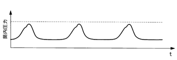
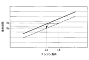
- FIG. 1 is a schematic configuration view showing an engine control system according to a first embodiment of the present invention. It is a control map of the calorific value measurement value of the fuel gas in the specific engine load of the engine control system concerning a 1st embodiment of the present invention, the injection period, and the maximum injection quantity. It is the graph which showed the time progress of the in-cylinder pressure of the engine concerning a 1st embodiment of the present invention. It is the graph which showed the time progress of the in-cylinder pressure of the conventional engine. It is a graph of the engine load of the engine control system concerning a 2nd embodiment of the present invention, and the injection period of fuel gas. It is the graph which showed the elapsed time of the calorific value measurement value of fuel gas, and the maximum injection quantity concerning a 2nd embodiment of the present invention.
- the engine control system 1 mainly includes a control unit 20, a calorific value meter (heat amount measuring means) 50, and a flow meter (flow rate measuring means) 60, and from the fuel gas tank 30 through the fuel gas injection valve 40 Control of the fuel gas supplied to the engine 10;
- the engine control system 1, the engine 10, the fuel gas tank 30, and the fuel gas injection valve 40 are mounted on a ship.
- the engine 10 is used as a main engine of a ship.
- LNG liquefied natural gas
- BOG boil-off gas
- the fuel gas supplied from the fuel gas tank 30 is injected and supplied from the fuel gas injection valve 40 to the engine 10, and is burned in the engine 10. Further, the air taken into the engine 10 to be used for the combustion is combusted with the fuel gas and then discharged as the exhaust gas to the outside of the engine 10.
- the fuel gas injection valve 40 provided in the engine 10 is controlled by a solenoid valve.
- a calorific value meter 50 and a flow meter 60 are installed in the fuel gas flow path 70 from the fuel gas tank 30 to the engine 10.
- the distance of the fuel gas passage 70 between the calorimeter 50 and the flow meter 60 is L1
- the distance of the fuel gas passage 70 between the flow meter 60 and the engine 10 is L2.
- the calorific value meter 50 measures the calorific value of the fuel gas supplied to the engine 10.
- the control unit 20 acquires the calorific value measurement value information in real time from the calorific value meter 50.
- the flow meter 60 measures the flow rate of the fuel gas supplied to the engine 10.
- the control unit 20 acquires real-time fuel gas flow rate information from the flow meter 60.
- the control unit 20 also acquires real-time engine load information.
- the control unit 20 is, for example, a computer, and communicates with a main storage device such as a central processing unit (CPU), a random access memory (RAM), an auxiliary storage device such as a hard disk drive (HDD), and external devices. It is comprised by the communication apparatus etc. which transmit and receive information by this.
- Various programs for example, application software
- the CPU reads out the programs from the auxiliary storage device to the main storage device and executes various programs.
- the fuel gas stored in the fuel gas tank 30 is mainly composed of methane when it is derived from LNG.
- Other components include several to several tens of propane, butane and the like.
- the liquid phase and the gas phase exist in the fuel gas tank 30, the boiling points of methane and the other components are different, so the component ratio of methane and the other components is different in the liquid phase and the gas phase.
- the calorific value differs between methane and the other components, the calorific value per unit of the gas phase and the calorific value per unit of the liquid phase are different.
- the engine control system 1 and the fuel gas tank 30 are mounted on a ship, the engine control system 1 and the fuel gas tank 30 swing due to an influence from the outside such as navigation. Therefore, the mixing ratio of the gas phase and the liquid phase in the fuel gas tank 30 is irregularly fluctuated by the swing of the fuel gas tank 30, and the calorific value of the fuel gas supplied from the fuel gas tank 30 is irregular. fluctuate.
- the calorific value of propane and butane which are components other than methane, is about twice that of methane. Therefore, when fuel gas is injected in a state where the amount of propane or butane with respect to methane changes while the engine output is operating at a constant level, abnormal combustion or insufficient output occurs unless the injection amount is controlled. I will.
- the calorific value fluctuates in the increasing direction, the engine 10 causes abnormal combustion. This abnormal combustion is called knocking. When knocking occurs, the engine 10 is damaged due to pressure increase due to abnormal combustion and the like.
- the calorific value and flow rate of the fuel gas supplied to the engine 10 are measured by the calorific value meter 50 and the flow meter 60, and the fuel gas is measured according to the measurement value. Control of the injection valve 40 is performed.
- FIG. 2 shows a control map at a specific engine load of engine 10.
- the vertical axis is the injection period of the fuel gas injection valve 40
- the horizontal axis is the calorific value of the fuel gas
- the solid line is the maximum injection amount
- the dashed line is the injection period corresponding to the calorific value when the engine load of the engine 10 is 100%. It represents.
- the heating value of the fuel gas when the engine load of the engine 10 is 100% in the case of Q A the injection period of the fuel gas injection valve 40 has shown that the R A.
- the maximum injection amount is a limit value of the injection amount of the fuel gas injection valve 40 set for each engine load of the engine 10 in order to prevent damage to the engine 10. Therefore, the injection of the fuel gas exceeding the maximum injection amount is limited. As shown in FIG. 2, as the calorific value increases, the injection period becomes shorter, and the maximum injection amount decreases.
- the control unit 20 acquires engine load information of the engine 10, calorific value measurement value information of the fuel gas measured by the calorimeter 50, and fuel gas flow rate information measured by the flow meter 60.
- the distance of the fuel gas passage 70 until the fuel gas having the calorific value measurement value measured by the calorific value meter 50 reaches the engine 10 is L1 + L2, and the calorific value measured value by the calorific value meter 50 by the distance
- the arrival of the fuel gas to the engine 10 is delayed. Therefore, the arrival time of the fuel gas of the calorific value measurement value to the engine 10 can be predicted from the flow rate and the reach distance of the fuel gas with respect to the combustion of the fuel gas in the cylinder of the engine 10.
- the control unit 20 predicts the arrival time from the engine load, the fuel gas flow rate and the distance L1 + L2. Further, the control unit 20 selects a control map according to the engine load from the engine load of the engine 10. For example, it is assumed that the control unit 20 selects the control map of FIG.
- the control unit 20 since when the heat quantity measurement value of the engine load is 100% and the engine 10 is Q B, the injection period of the fuel gas injection valve 40 corresponding thereto is R B, the calorific value of Q B the fuel gas in the heating value measurements after obtaining a measured value to predict the arrival time to reach the engine 10, the control so that just before the arrival time of the injection period of the fuel gas injection valve 40 to R B Do.
- the calorific value meter 50 detects the calorific value fluctuation, and the engine load and fuel gas Since the arrival time to the engine 10 is predicted from the flow rate and the fuel gas injection valve 40 is controlled, proper control can be performed before abnormal combustion occurs to avoid knocking.
- the calorific value meter 50 since the calorific value measurement value of the fuel gas is Q A and the injection period of the fuel gas injection valve 40 is controlled by R A , the calorific value meter 50 also detects the calorific value measurement value Q C Regardless of this, if the engine is operated in the injection period RA as it is, the maximum injection amount will be exceeded, and the engine 10 will be knocked. Therefore, the heat generation amount measurement value of the fuel gas is predicted arrival time to reach the engine 10 when the engine load is 100% and the engine 10 is Q C, the injection period of the fuel gas injection valve 40 in this just before reaching R Control is performed so as to be less than D , preferably R C.
- control of the fuel gas injection valve 40 by the control unit 20 changes the injection period of the fuel gas injection valve 40 to change the injection amount, or the injection timing of the fuel gas injection valve 40 It is to change. For example, when a calorific value larger than the calorific value of the fuel gas required by the engine 10 is supplied, control for reducing the injection amount by shortening the injection period of the fuel gas injection valve 40 or the fuel gas injection valve 40 Control to delay the injection timing is performed.
- the calorific value meter 50 detects the calorific value fluctuation, and the engine load and fuel gas flow rate to the engine 10 The arrival time of the fuel gas injection valve 40 is controlled to increase the injection amount, or the injection timing of the fuel gas injection valve 40 is advanced.
- FIG. 3 shows the time course of the in-cylinder pressure of the engine as an effect of the control of the fuel gas injection valve 40 according to the present embodiment.
- the vertical axis represents the in-cylinder pressure of the engine 10
- the horizontal axis represents time.
- the solid line represents the transition of the in-cylinder pressure
- the broken line represents a limit value at which in-cylinder pressure in the engine 10 may be knocked. That is, when the solid line exceeds the broken line, the engine 10 is knocking.
- the in-cylinder pressure may exceed the limit value even if it approaches the limit value as shown by the solid line in FIG. Absent.
- FIG. 4 shows a graph showing the time course of the in-cylinder pressure of the conventional engine.
- the vertical axis represents the in-cylinder pressure of the engine 10
- the horizontal axis represents time
- the solid line represents the transition of the in-cylinder pressure
- the broken line represents the in-cylinder determined that knocking has occurred in the engine 10. It is a pressure.
- knocking occurs beyond the broken line. The occurrence of this knocking is judged by the measured value of the in-cylinder pressure, and the fuel gas injection valve is controlled based on this.
- knocking even if control of the fuel gas injection valve is performed after knocking occurs in the first cycle, knocking also occurs in the second cycle if a control delay occurs. Thereafter, control of the fuel gas injection valve returns the engine to normal combustion, and knocking does not occur in the third cycle.
- the pressure in the cylinder is measured, and the fuel gas injection valve is controlled accordingly. Therefore, even in the occurrence of knocking, the occurrence of knocking is detected, and thereafter the fuel gas injection valve is controlled, so the frequency of occurrence of knocking is high. Since the engine is damaged when an excessive in-cylinder pressure rise occurs due to knocking, the higher the frequency of knocking, the higher the probability that the engine will be damaged.
- the fuel gas injection valve 40 for injecting fuel to the engine 10 driven by the fuel gas the calorific value meter 50 for measuring the calorific value of the fuel gas
- the control unit 20 for controlling the fuel gas injection valve 40 The control unit 20 predicts the arrival time of the fuel gas having the calorific value measurement value measured by the calorific value meter 50 to reach the engine 10, and controls the fuel gas injection valve 40 according to the calorific value measurement value and the achievement time.
- the calorific value of the fuel gas fluctuates, the calorific value fluctuation is predicted in advance, and the appropriate fuel gas injection amount is adjusted according to the calorific value of the fuel gas supplied to the engine 10 can do. Further, the control of the fuel gas injection valve 40 can be performed before knocking occurs. As a result, the engine 10 can be stably operated by restraining in advance that the fuel gas of the engine 10 runs short and can not take out a necessary output, and that the fuel gas is excessively supplied and knocking occurs in advance.
- control unit 20 stores in advance a control map in which the calorific value measurement value of the fuel gas and the injection period of the fuel gas injection valve 40 are correlated and mapped for each engine load of the engine 10. Since the injection period of the fuel gas injection valve 40 is acquired from the control map and controlled based on the engine load of 10 and the calorific value measurement value, the fuel gas injection valve according to the engine load of the engine 10 and the calorific value of fuel gas 40 adjustments are possible. Further, even if the calorific value of the fuel gas fluctuates, the fuel gas injection valve 40 is controlled accordingly, so that the fuel gas can be appropriately supplied to the engine 10, and the stable operation of the engine 10 can be performed.
- control unit 20 stores in advance a control map in which the calorific value measurement value of the fuel gas and the maximum injection amount of the fuel gas injection valve are associated and mapped for each engine load of the engine 10. Since the maximum injection amount is the limit value when knocking occurs and the engine may be damaged, using the control map including the maximum injection amount causes knocking according to the load and calorific value measurement value of the engine Control of the fuel gas injection valve 40 can be performed so as not to cause this.
- control unit 20 determines that the injection period of the fuel gas injection valve 40 acquired from the control map based on the calorific value is predicted to exceed the maximum injection amount in the calorific value at the arrival time, By performing control to reduce the injection amount of fuel gas to the fuel gas injection valve 40 before, knocking can be avoided before knocking occurs.
- control unit 20 determines that the injection period of the fuel gas injection valve 40 acquired from the control map based on the calorific value is predicted to exceed the maximum injection amount in the calorific value at the arrival time, Since the fuel gas injection valve 40 is controlled to delay the injection timing of the fuel gas, knocking can be avoided before knocking occurs.
- the engine 10 since the engine 10 includes any one of the above-described engine control systems 1, an appropriate fuel gas injection amount from the calorific value of the fuel gas supplied to the engine 10 and the arrival time of the fuel gas reaching the engine Is adjusted. Therefore, the engine 10 can be operated stably by suppressing in advance that the fuel gas is insufficient for the engine load and the required output can not be taken out, and that the fuel gas is excessively supplied for the engine load and knocking occurs. It can be carried out.
- the ship since the ship is equipped with the above-described engine 10, it is driven by the engine 10 whose injection amount of the fuel gas is controlled appropriately from the calorific value of the supplied fuel gas and the arrival time of the fuel gas reaching the engine. For this reason, the engine 10 can be operated stably by preventing in advance that the fuel gas is insufficient for the engine load to take out a necessary output, and that the fuel gas is excessively supplied for the engine load to cause knocking to occur. , The ship can perform stable operation.
- the maximum injection amount is set by the control map.
- the calorific value of the fuel gas fluctuates in the higher direction
- the calorific value fluctuates in maximum.
- the value of the injection amount is changed.
- the other points are the same as in the first embodiment, so the same reference numerals are given to the same components, and the description thereof is omitted.
- FIG. 5 shows a graph of the engine load and the fuel gas injection period of the engine control system according to the present embodiment.
- the vertical axis is the injection period of the fuel gas injection valve 40
- the horizontal axis is the engine load of the engine 10
- the solid line is the maximum injection amount
- the dashed line is the injection period when the load of the engine 10 is 100%. It represents.
- the injection period becomes longer, and the maximum injection amount increases.
- the engine load of the engine 10 constantly fluctuates, and accordingly, the control unit 20 needs to finely control the injection period of the fuel gas injection valve 40 so as to follow.
- the engine load of the engine 10 is maintained by varying the injection period to correspond to the engine load.
- the fuel gas injection valve 40 is controlled by a solenoid valve so as to follow the fluctuation of the engine load by finely controlling ON / OFF.
- ON / OFF the fine control of ON / OFF of the solenoid valve
- the fuel gas injection valve 40 can not control the injection period so as to follow the engine load, and injects a large amount of fuel gas to the reduced load.
- the injection period follows to be R b .
- the injection period is shortened gradually injection period by control over ON / OFF of the solenoid valve so as to move on the broken line from R b to R a Should follow.
- a delay occurs in the follow-up of the fuel gas injection valve 40 by limiting the follow-up due to the electromagnetic valve, rapidly value remains a predetermined time as shown by a dashed line was maintained R b, from then R b to R a Will decrease. At this time, R b is maintained for a predetermined time, and the injection amount is injected more by the surplus amount of R b -R a. However, since the maximum injection amount (solid line) is set, the maximum injection amount The excess fuel gas is not injected.
- FIG. 6 is a graph showing the elapsed time of the calorific value measurement value of the fuel gas and the maximum injection amount according to the second embodiment of the present invention.
- the vertical axis represents the calorific value of the fuel gas
- the horizontal axis represents time
- the solid line represents the transition of the calorific value of the fuel gas.
- the vertical axis represents the maximum injection amount
- the horizontal axis represents time
- the solid line represents the transition of the maximum injection amount.
- the calorific value of the fuel gas fluctuates continuously as time passes. Further, the heating value of the fuel gas, the first predetermined value Q 1 and the second predetermined value Q 2 is set. The second predetermined value Q 2 and a first value smaller than the predetermined value Q 1. Heating value of the fuel gas is the second case of the first is less than the predetermined value Q 1 greater than the predetermined value Q 2, that is, the first predetermined value Q 1 second value between the predetermined value Q 2 In this case, the standard value is taken.
- the calorific value of the fuel gas supplied from the fuel gas tank 30 fluctuates irregularly.
- methane, propane, butane, etc. which are other components, continuously exist in the methane, and the distribution thereof is distributed more slowly than the engine cycle (for example, about 1 second). It is predicted that Therefore, if the calorific value is measured in time series by the calorific value meter 50, the fluctuation of the calorific value of the fuel gas can be predicted.
- maximum injection quantity M t is set, it is possible to increase the injection period of the fuel gas injection valve 40, and thereby possible to increase the injection quantity.
- the maximum injection amount Mt is a value set by the tendency of transition of the calorific value of the fuel gas, and is a fluctuating value to be set according to the tendency.
- the heating value exceeds the second predetermined value Q 2
- M m is set to the maximum injection quantity at the same time.
- the predetermined value Q 1 first heating value from the transition It is predicted to exceed. Specifically, the prediction of the transition of the calorific value exceeds the first predetermined value Q1, and the differential value in the transition of the calorific value of the unit time ⁇ t exceeds a certain value. If the calorific value of the fuel gas becomes too high, knocking may occur, which may lead to damage to the engine 10.
- the first predetermined value Q 1 at a timing before the exceeding, to set the maximum injection quantity M b in the case of the first high heat value than the predetermined value Q 1. That is, in a first time t 3 is a time earlier than the time t 4 when it is expected that more than a predetermined value Q 1, the maximum injection quantity M b value smaller than the standard value M m of the maximum injection quantity Set By maximum injection quantity M b is set, the injection period of the fuel gas injection valve 40 can be suppressed short and thereby enabling to reduce the injection amount.
- the maximum injection amount Mb is a value set by the tendency of transition of the calorific value of the fuel gas, and is a value which fluctuates according to the tendency.
- Control unit 20 when the heating value measurements may be expected to exceed the first predetermined value Q 1, since reducing the maximum injection quantity before exceeding the first predetermined value Q 1, the fuel gas injection valve The injection period of 40 can be shortened to suppress the injection amount. Moreover, damage to the engine 10 due to knocking can be prevented by changing the maximum injection amount to a small amount before the fuel gas having a high calorific value is consumed.
- Control unit 20 when the heating value measurements may be expected to fall below the predetermined value Q 2 small second than the first predetermined value Q 1, the maximum injection quantity at the same time as the second below a predetermined value Q 2 Since it is possible to increase the injection period of the fuel gas injection valve 40 and to increase the injection amount, it is possible to increase the injection amount. Further, by allowing the maximum injection amount to be increased when the fuel gas having a low calorific value is consumed, the output of the engine 10 can be prevented from being insufficient.
- the engine 10 provided with the engine control system 1 is an engine mounted on a ship, but may be a stationary engine.
- the predetermined value of the calorific value of the fuel gas first by setting the predetermined value Q 1 and the second predetermined value Q 2 and to control the injection amount of the fuel gas
- the injection amount of fuel gas may be controlled by setting a predetermined value. In this case, the injection amount of the fuel gas can be controlled more finely.
Landscapes
- Engineering & Computer Science (AREA)
- Chemical & Material Sciences (AREA)
- Combustion & Propulsion (AREA)
- Mechanical Engineering (AREA)
- General Engineering & Computer Science (AREA)
- Chemical Kinetics & Catalysis (AREA)
- General Chemical & Material Sciences (AREA)
- Oil, Petroleum & Natural Gas (AREA)
- Electrical Control Of Air Or Fuel Supplied To Internal-Combustion Engine (AREA)
- Combined Controls Of Internal Combustion Engines (AREA)
Abstract
燃料ガスの発熱量の変動に対応可能なエンジン制御システム及びこれを備えたエンジン並びにこれを備えた船舶、及びエンジン制御方法を提供することを目的とする。エンジン制御システム(1)は、燃料ガスによって運転されるエンジン(10)へ燃料を噴射する燃料ガス噴射弁(40)と、燃料ガスの発熱量を計測する発熱量計(50)と、燃料ガス噴射弁(40)を制御する制御部(20)と、を備え、制御部(20)は、発熱量計(50)によって計測された発熱量計測値を有する燃料ガスがエンジン(10)に到達する到達時間を予測し、発熱量計測値及び到達時間に応じて燃料ガス噴射弁(40)の制御を行う。
Description
本発明は、エンジン制御システム及びこれを備えたエンジン並びにこれを備えた船舶、及びエンジン制御方法に関するものである。
燃料ガスを燃料として用いるエンジンにおいては、発熱量が高くかつ発熱量が変動しないガスを燃料ガスとして用いることで安定した運転を行うことができる。
しかし、供給される燃料ガスの発熱量が変動する場合には、エンジンの運転が不安定になる恐れがある。
そこで、例えば特許文献1では、燃料ガスの単位体積当たりの発熱量を計測し、その計測結果に基づいてエンジンの空燃比、点火タイミング及び高発熱量燃料ガスの供給を制御することが開示されている。
また、特許文献2には、筒内圧力を検出し、筒内最高圧力の過昇やノッキング発生などの過大な筒内圧力となる過剰燃焼が検知されると、補助燃料ガスの供給量を減少させることが開示されている。
しかし、供給される燃料ガスの発熱量が変動する場合には、エンジンの運転が不安定になる恐れがある。
そこで、例えば特許文献1では、燃料ガスの単位体積当たりの発熱量を計測し、その計測結果に基づいてエンジンの空燃比、点火タイミング及び高発熱量燃料ガスの供給を制御することが開示されている。
また、特許文献2には、筒内圧力を検出し、筒内最高圧力の過昇やノッキング発生などの過大な筒内圧力となる過剰燃焼が検知されると、補助燃料ガスの供給量を減少させることが開示されている。
しかしながら、上記特許文献1及び2に開示された発明では、定置用のエンジンに関する発明であるため、例えば船舶に搭載されるエンジンなどのように、供給される燃料ガスの貯留タンクがエンジン運転時に揺動することにより燃料ガスが有する発熱量の変動をコントロールできない場合について検討されていないという問題があった。
また、筒内の異常な状態(例えばノッキング)を回避するために特許文献1及び2の技術を用いる場合、筒内の異常な状態を計測してそれをもとに判断し制御するため、制御を行う前提として筒内に異常な状態が発生している必要があった。つまり、制御を行う前に筒内が極端に異常な状態となることによりエンジンにダメージを与えてしまう可能性があった。
また、筒内の異常な状態(例えばノッキング)を回避するために特許文献1及び2の技術を用いる場合、筒内の異常な状態を計測してそれをもとに判断し制御するため、制御を行う前提として筒内に異常な状態が発生している必要があった。つまり、制御を行う前に筒内が極端に異常な状態となることによりエンジンにダメージを与えてしまう可能性があった。
本発明は、このような事情に鑑みてなされたものであって、燃料ガスの発熱量の変動に対応可能なエンジン制御システム及びこれを備えたエンジン並びにこれを備えた船舶、及びエンジン制御方法を提供することを目的とする。
上記課題を解決するために、本発明のエンジン制御システム及びこれを備えたエンジン並びにこれを備えた船舶、及びエンジン制御方法は以下の手段を採用する。
本発明の第1態様に係るエンジン制御システムは、燃料ガスによって運転されるエンジンへ燃料を噴射する燃料ガス噴射弁と、前記燃料ガスの発熱量を計測する発熱量計測手段と、前記燃料ガス噴射弁を制御する制御部と、を備え、前記制御部は、前記発熱量計測手段によって計測された発熱量計測値を有する前記燃料ガスが前記エンジンに到達する到達時間を予測し、前記発熱量計測値及び前記到達時間に応じて前記燃料ガス噴射弁の制御を行う。
本発明の第1態様に係るエンジン制御システムは、燃料ガスによって運転されるエンジンへ燃料を噴射する燃料ガス噴射弁と、前記燃料ガスの発熱量を計測する発熱量計測手段と、前記燃料ガス噴射弁を制御する制御部と、を備え、前記制御部は、前記発熱量計測手段によって計測された発熱量計測値を有する前記燃料ガスが前記エンジンに到達する到達時間を予測し、前記発熱量計測値及び前記到達時間に応じて前記燃料ガス噴射弁の制御を行う。
本発明の第1態様によれば、燃料ガスによって運転されるエンジンへ燃料を噴射する燃料ガス噴射弁と、燃料ガスの発熱量を計測する発熱量計測手段と、燃料ガス噴射弁を制御する制御部と、を備え、制御部は、発熱量計測手段によって計測された発熱量計測値を有する燃料ガスがエンジンに到達する到達時間を予測し、発熱量計測値及び到達時間に応じて燃料ガス噴射弁の制御を行うことから、燃料ガスの発熱量が変動する場合であっても、あらかじめ発熱量変動を予測してエンジンに供給される燃料ガスの発熱量に応じた適切な燃料ガスの噴射量を調整することができる。また、ノッキング(異常燃焼)が発生する前に燃料ガス噴射弁の制御を行うことができる。これにより、エンジンの燃料ガスが不足して必要な出力を取り出せないことや、燃料ガスが供給過多になりノッキングが発生することを予め抑止し、エンジンの安定稼働を行うことができる。
上記第1態様において、前記制御部は、予め前記エンジンのエンジン負荷ごとに前記燃料ガスの前記発熱量計測値と前記燃料ガス噴射弁の噴射期間とを関連づけてマッピングした制御マップを記憶しておき、前記エンジンの前記エンジン負荷と前記発熱量計測値に基づき前記制御マップから前記燃料ガス噴射弁の前記噴射期間を取得し、前記燃料ガス噴射弁の制御を行うこととしてもよい。
本発明の第1態様によれば、制御部は、予めエンジンのエンジン負荷ごとに、燃料ガスの発熱量計測値と燃料ガス噴射弁の噴射期間とを関連づけてマッピングした制御マップを記憶しておき、運転中のエンジンのエンジン負荷と発熱量計測値に基づき制御マップから燃料ガス噴射弁の噴射期間を取得して制御を行うことから、エンジンのエンジン負荷および燃料ガスの発熱量計測値に応じた燃料ガス噴射弁の調整が可能である。また、燃料ガスの発熱量が変動しても、それに応じて燃料ガス噴射弁を制御することから、エンジンに対して適切な燃料ガス供給が行え、安定したエンジンの運転ができる。
上記第1態様において、前記制御部は、予め前記エンジンの前記エンジン負荷ごとに前記燃料ガスの前記発熱量計測値と前記エンジンに異常燃焼が発生する場合の前記燃料ガス噴射弁の限界値である最大噴射量とを関連づけてマッピングした前記制御マップを記憶しておき、前記エンジンの前記エンジン負荷と前記発熱量計測値に基づき前記制御マップから前記燃料ガス噴射弁の前記噴射期間及び前記最大噴射量を取得し、前記燃料ガス噴射弁の制御を行うこととしてもよい。
本発明の第1態様によれば、制御部は、予めエンジンのエンジン負荷ごとに、燃料ガスの発熱量計測値と燃料ガス噴射弁の最大噴射量とを関連づけてマッピングした制御マップを記憶する。最大噴射量は、ノッキングを起こしエンジンが損傷する恐れがある時の限界値であることから、最大噴射量を含む制御マップを用いることで、エンジンの負荷及び発熱量計測値に応じてノッキングを発生させないように燃料ガス噴射弁の制御を行うことができる。
上記第1態様において、前記制御部は、前記発熱量計測手段によって計測された前記発熱量計測値に基づき前記制御マップから取得した前記燃料ガス噴射弁の前記噴射期間が前記到達時間に前記発熱量計測値における前記最大噴射量を超えることが予測される場合に、前記到達時間前に前記燃料ガス噴射弁に対し前記燃料ガスの噴射量を減らす制御を行うこととしてもよい。
本発明の第1態様によれば、制御部は、発熱量計測値に基づき制御マップから取得した燃料ガス噴射弁の噴射期間が到達時間にその発熱量計測値における最大噴射量を超えることが予測される場合に、到達時間前に燃料ガス噴射弁に対し燃料ガスの噴射量を減らす制御を行うことから、ノッキングが発生する前に燃料ガスの噴射量を減らすことでノッキングを回避することができる。
上記第1態様において、前記制御部は、前記発熱量計測手段によって計測された前記発熱量計測値に基づき前記制御マップから取得した前記燃料ガス噴射弁の前記噴射期間が前記到達時間に前記発熱量計測値における前記最大噴射量を超えることが予測される場合に、前記到達時間前に前記燃料ガス噴射弁に対し前記燃料ガスの噴射タイミングを遅らせる制御を行うこととしてもよい。
本発明の第1態様によれば、制御部は、発熱量計測値に基づき制御マップから取得した燃料ガス噴射弁の噴射期間が到達時間にその発熱量計測値における最大噴射量を超えることが予測される場合に、到達時間前に燃料ガス噴射弁に対し燃料ガスの噴射タイミングを遅らせる制御を行うことから、ノッキングが発生する前に燃料ガスの噴射タイミングを遅らせることでノッキングを回避することができる。
上記第1態様において、前記制御部は、前記発熱量計測手段によって計測された前記発熱量計測値が第1の所定値を超えることが予測される場合、前記燃料ガスの前記発熱量計測値が前記第1の所定値を超える前に前記最大噴射量を小さくすることとしてもよい。
本発明の第1態様によれば、制御部は、発熱量計測値が第1の所定値を超えることが予測される場合、第1の所定値を超える前に最大噴射量を小さくすることから、燃料ガス噴射弁の噴射期間を短くし噴射量を抑えることが可能となる。また、発熱量が高い燃料ガスが消費される前に最大噴射量を小さく変更することで、ノッキングによるエンジンの損傷を防止することができる。
上記第1態様において、前記制御部は、前記発熱量計測手段によって計測された前記発熱量計測値が第1の所定値よりも小さい第2の所定値を下回ることが予測される場合、前記発熱量計測値が前記第2の所定値を下回ると同時に前記最大噴射量を大きくすることとしてもよい。
本発明の第1態様によれば、制御部は、発熱量計測値が第1の所定値よりも小さい第2の所定値を下回ることが予測される場合、第2の所定値を下回ると同時に最大噴射量を大きくすることから、燃料ガス噴射弁の噴射期間を長くし、噴射量を多くすることを許容できる。また、発熱量が低い燃料ガスが消費される時に最大噴射量を大きくすることを許容することにより、エンジンの出力が不足するのを防ぐことができる。
本発明の第2態様は、上記のいずれかに記載されたエンジン制御システムを備えたエンジンを採用する。
本発明の第2態様によれば、エンジンは、前述のいずれかのエンジン制御システムを備えることから、エンジンに対し供給される燃料ガスの発熱量とその燃料ガスがエンジンに到達する到達時間から適切な燃料ガスの噴射量が制御される。そのため、エンジンの負荷に対して燃料ガスが不足して必要な出力を取り出せないことや、エンジンの負荷に対して燃料ガスが供給過多になりノッキングが発生することを予め抑止し、エンジンは安定稼働を行うことができる。
本発明の第3態様は、上記に記載されたエンジンを搭載する船舶を採用する。
本発明の第3態様によれば、船舶は前述のエンジンを搭載することから、供給される燃料ガスの発熱量とその燃料ガスがエンジンに到達する到達時間から適切な燃料ガスの噴射量が制御されるエンジンにより駆動する。そのため、エンジンの負荷に対して燃料ガスが不足して必要な出力を取り出せないことやエンジンの負荷に対して燃料ガスが供給過多になりノッキングが発生することを予め抑止し、エンジンが安定稼働するため、船舶は安定した運行を行うことができる。
本発明の第4態様に係るエンジン制御方法は、発熱量計測値を有する燃料ガスがエンジンに到達する到達時間を予測するステップと、前記発熱量計測値及び前記到達時間に応じて燃料ガス噴射弁の制御を行うステップと、を備える。
本発明の第4態様によれば、発熱量計測値を有する燃料ガスがエンジンに到達する到達時間を予測するステップと、発熱量計測値及び到達時間に応じて燃料ガス噴射弁の制御を行うステップと、を備えることから、燃料ガスの発熱量が変動する場合であっても、あらかじめ発熱量変動を予測してエンジンに供給される燃料ガスの発熱量に応じた適切な燃料ガスの噴射量を調整することができる。また、ノッキングが発生する前に燃料ガス噴射弁の制御を行うことができる。これにより、エンジンの燃料ガスが不足して必要な出力を取り出せないことや、燃料ガスが供給過多になりノッキングが発生することを予め抑止し、エンジンの安定稼働を行うことができる。
本発明によれば、変動する発熱量に応じて燃料ガス噴射弁の制御を行うので、ノッキングなどの筒内の異常な状態を回避することができる。
また、本発明によれば、筒内の異常な状態を事前に予測し回避することから、エンジンの損傷を抑止することができる。
また、本発明によれば、筒内の異常な状態を事前に予測し回避することから、エンジンの損傷を抑止することができる。
以下に、本発明に係るエンジン制御システム及びこれを備えたエンジン並びにこれを備えた船舶、及びエンジン制御方法の一実施形態について、図面を参照して説明する。
〔第1実施形態〕
以下、本発明の第1実施形態について、図1を用いて説明する。
図1には、本実施形態に係るエンジン制御システムが示されている。
エンジン制御システム1は、制御部20と、発熱量計(発熱量計測手段)50と、流量計(流量計測手段)60とを主な構成として備え、燃料ガスタンク30から燃料ガス噴射弁40を介してエンジン10へ供給される燃料ガスの制御を行う。
本実施形態では、エンジン制御システム1、エンジン10、燃料ガスタンク30及び燃料ガス噴射弁40は、船舶に搭載されている。この場合、エンジン10は船舶の主機として用いられる。例えば、液化天然ガス(LNG)を運搬する船舶であるならば、運搬するLNGの余剰分やLNGのボイルオフガス(BOG)を燃料ガスとして用いることが可能である。
〔第1実施形態〕
以下、本発明の第1実施形態について、図1を用いて説明する。
図1には、本実施形態に係るエンジン制御システムが示されている。
エンジン制御システム1は、制御部20と、発熱量計(発熱量計測手段)50と、流量計(流量計測手段)60とを主な構成として備え、燃料ガスタンク30から燃料ガス噴射弁40を介してエンジン10へ供給される燃料ガスの制御を行う。
本実施形態では、エンジン制御システム1、エンジン10、燃料ガスタンク30及び燃料ガス噴射弁40は、船舶に搭載されている。この場合、エンジン10は船舶の主機として用いられる。例えば、液化天然ガス(LNG)を運搬する船舶であるならば、運搬するLNGの余剰分やLNGのボイルオフガス(BOG)を燃料ガスとして用いることが可能である。
エンジン10には、燃料ガスタンク30から供給された燃料ガスが燃料ガス噴射弁40から噴射、供給され、エンジン10内部で燃焼される。また、燃焼に用いるためにエンジン10に取り込まれた空気は、燃料ガスとともに燃焼された後に排気となってエンジン10外部へ排出される。エンジン10に備えられた燃料ガス噴射弁40は、電磁弁により制御される。
燃料ガスタンク30からエンジン10への燃料ガス流路70には、発熱量計50及び流量計60が設置されている。発熱量計50と流量計60との間の燃料ガス流路70の距離はL1、流量計60とエンジン10との間の燃料ガス流路70の距離はL2である。
燃料ガスタンク30からエンジン10への燃料ガス流路70には、発熱量計50及び流量計60が設置されている。発熱量計50と流量計60との間の燃料ガス流路70の距離はL1、流量計60とエンジン10との間の燃料ガス流路70の距離はL2である。
発熱量計50は、エンジン10に供給される燃料ガスの発熱量を計測する。制御部20は、発熱量計50から実時間の発熱量計測値情報を取得する。
流量計60は、エンジン10に供給される燃料ガスの流量を計測する。制御部20は、流量計60から実時間の燃料ガス流量情報を取得する。
また制御部20は、実時間のエンジン負荷情報を取得する。
流量計60は、エンジン10に供給される燃料ガスの流量を計測する。制御部20は、流量計60から実時間の燃料ガス流量情報を取得する。
また制御部20は、実時間のエンジン負荷情報を取得する。
制御部20は、たとえばコンピュータであり、CPU(中央演算処理装置)、RAM(Random Access Memory)等の主記憶装置、HDD(Hard Disk Drive)等の補助記憶装置、外部の機器と通信を行うことにより情報の授受を行う通信装置等などで構成されている。補助記憶装置には、各種プログラム(例えば、アプリケーションソフトウェア)が格納されており、CPUが補助記憶装置から主記憶装置にプログラムを読み出し、実行することにより種々の処理を実現させる。
燃料ガスタンク30に貯蔵されている燃料ガスは、LNG由来の場合、メタンが主成分とされている。その他の成分としては、数%から数十%のプロパン、ブタンなどが含まれている。
燃料ガスタンク30内では液相と気相とが存在するが、メタンとその他の成分との沸点が異なることから、液相と気相とではメタンやその他の成分の成分比が異なる。さらに、メタンとその他の成分とは発熱量が異なるため、気相の単位当たりの発熱量と液相の単位当たりの発熱量とはその発熱量が異なる。
一方、エンジン制御システム1及び燃料ガスタンク30は、船舶に搭載されていることから航行など外部からの影響により揺動する。よって、燃料ガスタンク30の揺動により、燃料ガスタンク30内の気相と液相との混合割合が不定期に変動することになり、燃料ガスタンク30から供給される燃料ガスの発熱量は不定期に変動する。
燃料ガスタンク30内では液相と気相とが存在するが、メタンとその他の成分との沸点が異なることから、液相と気相とではメタンやその他の成分の成分比が異なる。さらに、メタンとその他の成分とは発熱量が異なるため、気相の単位当たりの発熱量と液相の単位当たりの発熱量とはその発熱量が異なる。
一方、エンジン制御システム1及び燃料ガスタンク30は、船舶に搭載されていることから航行など外部からの影響により揺動する。よって、燃料ガスタンク30の揺動により、燃料ガスタンク30内の気相と液相との混合割合が不定期に変動することになり、燃料ガスタンク30から供給される燃料ガスの発熱量は不定期に変動する。
一般的に、メタン以外のその他の成分であるプロパン及びブタンの発熱量はメタンの発熱量の約2倍である。そのため、エンジン出力が一定で運転している状態で、メタンに対するプロパンやブタンの量が変化した状態の燃料ガスが噴射される場合は、噴射量を制御しない限り、異常燃焼や出力不足が生じてしまう。特に発熱量が増加方向に変動するとエンジン10が異常燃焼を起こす。この異常燃焼をノッキングという。ノッキングが発生すると、エンジン10は異常燃焼による圧力上昇などにより損傷を受ける。
そこで本実施形態では、ノッキングの発生を予め回避するため、エンジン10に供給される燃料ガスの発熱量と流量を、発熱量計50及び流量計60にて計測し、計測値に応じて燃料ガス噴射弁40の制御を行う。
そこで本実施形態では、ノッキングの発生を予め回避するため、エンジン10に供給される燃料ガスの発熱量と流量を、発熱量計50及び流量計60にて計測し、計測値に応じて燃料ガス噴射弁40の制御を行う。
予め、エンジン10の運転条件(エンジン10の負荷)、燃料ガスの発熱量及び燃料ガス噴射弁40の噴射期間と、ノッキングの有無の関係とを、試験にて把握する。この試験結果は、エンジン10のエンジン負荷ごとにマッピングを行うことで、制御マップとされる。
図2は、エンジン10の特定のエンジン負荷における制御マップを示している。縦軸は燃料ガス噴射弁40の噴射期間、横軸は燃料ガスの発熱量であり、実線は最大噴射量、破線はエンジン10のエンジン負荷が100%の場合の発熱量に応じた噴射期間を表している。例えば、燃料ガスの発熱量がQAの場合にエンジン10のエンジン負荷が100%の時、燃料ガス噴射弁40の噴射期間がRAとなることを示している。
また、最大噴射量とは、エンジン10の損傷を防ぐために、エンジン10のエンジン負荷ごとに設定された燃料ガス噴射弁40の噴射量の限界値である。したがって、最大噴射量を超えた燃料ガスの噴射は制限されることになる。
図2に示されるように、発熱量が高くなると、噴射期間は短くなり、また最大噴射量は少なくなる。
図2は、エンジン10の特定のエンジン負荷における制御マップを示している。縦軸は燃料ガス噴射弁40の噴射期間、横軸は燃料ガスの発熱量であり、実線は最大噴射量、破線はエンジン10のエンジン負荷が100%の場合の発熱量に応じた噴射期間を表している。例えば、燃料ガスの発熱量がQAの場合にエンジン10のエンジン負荷が100%の時、燃料ガス噴射弁40の噴射期間がRAとなることを示している。
また、最大噴射量とは、エンジン10の損傷を防ぐために、エンジン10のエンジン負荷ごとに設定された燃料ガス噴射弁40の噴射量の限界値である。したがって、最大噴射量を超えた燃料ガスの噴射は制限されることになる。
図2に示されるように、発熱量が高くなると、噴射期間は短くなり、また最大噴射量は少なくなる。
制御部20は、エンジン10のエンジン負荷情報と、発熱量計50が計測した燃料ガスの発熱量計測値情報と、流量計60が計測した燃料ガス流量情報とを取得する。
発熱量計50が計測した発熱量計測値を有する燃料ガスがエンジン10に到達するまでの燃料ガス流路70の距離はL1+L2であり、その距離分だけ発熱量計50が計測した発熱量計測値を有する燃料ガスのエンジン10への到達が遅れる。そこで、エンジン10の筒内における燃料ガスの燃焼に対する燃料ガスの流量及び到達距離から、発熱量計測値の燃料ガスのエンジン10への到達時間を予測することができる。すなわち、制御部20は、エンジン負荷、燃料ガス流量及び距離L1+L2より到達時間を予測する。
また制御部20は、エンジン10のエンジン負荷から、エンジン負荷に応じた制御マップを選択する。例えば制御部20が図2の制御マップを選択したものとする。制御部20は、発熱量計測値がQBでありエンジン10のエンジン負荷が100%である場合、これに対応する燃料ガス噴射弁40の噴射期間はRBであるため、QBの発熱量計測値を得てからこの発熱量計測値の燃料ガスがエンジン10に到達するまでの到達時間を予測し、この到達時間直前に燃料ガス噴射弁40の噴射期間をRBにするように制御を行う。
発熱量計50が計測した発熱量計測値を有する燃料ガスがエンジン10に到達するまでの燃料ガス流路70の距離はL1+L2であり、その距離分だけ発熱量計50が計測した発熱量計測値を有する燃料ガスのエンジン10への到達が遅れる。そこで、エンジン10の筒内における燃料ガスの燃焼に対する燃料ガスの流量及び到達距離から、発熱量計測値の燃料ガスのエンジン10への到達時間を予測することができる。すなわち、制御部20は、エンジン負荷、燃料ガス流量及び距離L1+L2より到達時間を予測する。
また制御部20は、エンジン10のエンジン負荷から、エンジン負荷に応じた制御マップを選択する。例えば制御部20が図2の制御マップを選択したものとする。制御部20は、発熱量計測値がQBでありエンジン10のエンジン負荷が100%である場合、これに対応する燃料ガス噴射弁40の噴射期間はRBであるため、QBの発熱量計測値を得てからこの発熱量計測値の燃料ガスがエンジン10に到達するまでの到達時間を予測し、この到達時間直前に燃料ガス噴射弁40の噴射期間をRBにするように制御を行う。
またエンジン10が必要な燃料ガスの発熱量よりも大きい発熱量の燃料ガスが燃料ガスタンク30から供給された場合であっても、発熱量計50が発熱量変動を検知し、エンジン負荷および燃料ガス流量からエンジン10への到達時間を予測し、燃料ガス噴射弁40の制御を行うため、異常燃焼が起きる前に適正な制御が行え、ノッキングを回避する。
例えば、燃料ガスの発熱量計測値がQAであるため燃料ガス噴射弁40の噴射期間をRAで制御している場合に、発熱量計50が発熱量計測値QCを検知したにもかかわらずそのまま噴射期間RAで運転すると、最大噴射量を超えることになり、エンジン10にノッキングが発生することになる。そこで、発熱量計測値がQCでありエンジン10のエンジン負荷が100%の場合に燃料ガスがエンジン10に到達する到達時間を予測し、この到達直前に燃料ガス噴射弁40の噴射期間をRD未満、好ましくはRCにするように制御を行う。
例えば、燃料ガスの発熱量計測値がQAであるため燃料ガス噴射弁40の噴射期間をRAで制御している場合に、発熱量計50が発熱量計測値QCを検知したにもかかわらずそのまま噴射期間RAで運転すると、最大噴射量を超えることになり、エンジン10にノッキングが発生することになる。そこで、発熱量計測値がQCでありエンジン10のエンジン負荷が100%の場合に燃料ガスがエンジン10に到達する到達時間を予測し、この到達直前に燃料ガス噴射弁40の噴射期間をRD未満、好ましくはRCにするように制御を行う。
ここで、制御部20による燃料ガス噴射弁40の制御とは、具体的には、燃料ガス噴射弁40の噴射期間を変えて噴射量を変更する、または、燃料ガス噴射弁40の噴射タイミングを変更することである。例えば、エンジン10が必要な燃料ガスの発熱量よりも大きい発熱量が供給される場合には、燃料ガス噴射弁40の噴射期間を短くして噴射量を減らす制御、または燃料ガス噴射弁40の噴射タイミングを遅らせる制御を行う。
また、エンジン10が必要な燃料ガスの発熱量よりも小さい発熱量が燃料ガスタンク30から供給された場合は、発熱量計50が発熱量変動を検知し、エンジン負荷および燃料ガス流量からエンジン10への到達時間を予測し、燃料ガス噴射弁40の噴射期間を長くして噴射量を増やす制御、または燃料ガス噴射弁40の噴射タイミングを早める制御を行う。
図3には、本実施形態による燃料ガス噴射弁40の制御による効果として、エンジンの筒内圧力の時間経過が示されている。
図3において、縦軸はエンジン10の筒内圧力、横軸は時間であり、実線が筒内圧力の推移、破線はエンジン10における筒内圧力のノッキング発生の恐れのある限界値である。すなわち、実線が破線を超えると、エンジン10にはノッキングが発生していることになる。
本実施形態では、ノッキングが発生する前にノッキングを予測して燃料ガス噴射弁40の制御を行うため、図3の実線のように筒内圧力が限界値に近づいても限界値を超えることがない。
図3において、縦軸はエンジン10の筒内圧力、横軸は時間であり、実線が筒内圧力の推移、破線はエンジン10における筒内圧力のノッキング発生の恐れのある限界値である。すなわち、実線が破線を超えると、エンジン10にはノッキングが発生していることになる。
本実施形態では、ノッキングが発生する前にノッキングを予測して燃料ガス噴射弁40の制御を行うため、図3の実線のように筒内圧力が限界値に近づいても限界値を超えることがない。
図4には、従来のエンジンの筒内圧力の時間経過を表すグラフが示されている。
図4において、図3と同様に、縦軸はエンジン10の筒内圧力、横軸は時間であり、実線が筒内圧力の推移、破線はエンジン10においてノッキングが発生したと判断される筒内圧力である。
図4の場合、1回目のサイクルに投入される燃料ガスの発熱量が通常より高くなることで筒内圧力が上がると、破線を超えてノッキングが発生する。このノッキングの発生有無を筒内圧力の計測値により判断し、これを元に燃料ガス噴射弁の制御を行う。ただし、1回目のサイクルにおいてノッキングが発生した後に燃料ガス噴射弁の制御を行っても、制御遅れが生じた場合には、2回目のサイクルにおいてもノッキングが発生してしまう。その後、燃料ガス噴射弁の制御によりエンジンは正常燃焼に戻り、3回目のサイクルはノッキングが発生していない。
このように、従来のエンジンは、例えば筒内圧力を計測し、それに応じて燃料ガス噴射弁の制御を行っている。そのため、ノッキングの発生においても、ノッキングしたことを検知し、その後に燃料ガス噴射弁の制御を行うことから、ノッキングが発生する頻度が高い。ノッキングにより過度の筒内圧力上昇が生じた場合にはエンジンが損傷を受けるため、ノッキングの頻度が高いほどエンジンが損傷を受ける確率が高くなる。
図4において、図3と同様に、縦軸はエンジン10の筒内圧力、横軸は時間であり、実線が筒内圧力の推移、破線はエンジン10においてノッキングが発生したと判断される筒内圧力である。
図4の場合、1回目のサイクルに投入される燃料ガスの発熱量が通常より高くなることで筒内圧力が上がると、破線を超えてノッキングが発生する。このノッキングの発生有無を筒内圧力の計測値により判断し、これを元に燃料ガス噴射弁の制御を行う。ただし、1回目のサイクルにおいてノッキングが発生した後に燃料ガス噴射弁の制御を行っても、制御遅れが生じた場合には、2回目のサイクルにおいてもノッキングが発生してしまう。その後、燃料ガス噴射弁の制御によりエンジンは正常燃焼に戻り、3回目のサイクルはノッキングが発生していない。
このように、従来のエンジンは、例えば筒内圧力を計測し、それに応じて燃料ガス噴射弁の制御を行っている。そのため、ノッキングの発生においても、ノッキングしたことを検知し、その後に燃料ガス噴射弁の制御を行うことから、ノッキングが発生する頻度が高い。ノッキングにより過度の筒内圧力上昇が生じた場合にはエンジンが損傷を受けるため、ノッキングの頻度が高いほどエンジンが損傷を受ける確率が高くなる。
以上、説明してきたように、本実施形態に係るエンジン制御システム及びこれを備えたエンジン並びにこれを備えた船舶、及びエンジン制御方法によれば、以下の作用効果を奏する。
燃料ガスによって運転されるエンジン10へ燃料を噴射する燃料ガス噴射弁40と、燃料ガスの発熱量を計測する発熱量計50と、燃料ガス噴射弁40を制御する制御部20と、を備え、制御部20は、発熱量計50によって計測された発熱量計測値を有する燃料ガスがエンジン10に到達する到達時間を予測し、発熱量計測値及び到達時間に応じて燃料ガス噴射弁40の制御を行うことから、燃料ガスの発熱量が変動する場合であっても、あらかじめ発熱量変動を予測してエンジン10に供給される燃料ガスの発熱量に応じた適切な燃料ガスの噴射量を調整することができる。また、ノッキングが発生する前に燃料ガス噴射弁40の制御を行うことができる。これにより、エンジン10の燃料ガスが不足して必要な出力を取り出せないことや、燃料ガスが供給過多になりノッキングが発生することを予め抑止し、エンジン10の安定稼働を行うことができる。
燃料ガスによって運転されるエンジン10へ燃料を噴射する燃料ガス噴射弁40と、燃料ガスの発熱量を計測する発熱量計50と、燃料ガス噴射弁40を制御する制御部20と、を備え、制御部20は、発熱量計50によって計測された発熱量計測値を有する燃料ガスがエンジン10に到達する到達時間を予測し、発熱量計測値及び到達時間に応じて燃料ガス噴射弁40の制御を行うことから、燃料ガスの発熱量が変動する場合であっても、あらかじめ発熱量変動を予測してエンジン10に供給される燃料ガスの発熱量に応じた適切な燃料ガスの噴射量を調整することができる。また、ノッキングが発生する前に燃料ガス噴射弁40の制御を行うことができる。これにより、エンジン10の燃料ガスが不足して必要な出力を取り出せないことや、燃料ガスが供給過多になりノッキングが発生することを予め抑止し、エンジン10の安定稼働を行うことができる。
また、制御部20は、予めエンジン10のエンジン負荷ごとに、燃料ガスの発熱量計測値と燃料ガス噴射弁40の噴射期間とを関連づけてマッピングした制御マップを記憶しておき、運転中のエンジン10のエンジン負荷と発熱量計測値に基づき制御マップから燃料ガス噴射弁40の噴射期間を取得して制御を行うことから、エンジン10のエンジン負荷および燃料ガスの発熱量に応じた燃料ガス噴射弁40の調整が可能である。また、燃料ガスの発熱量が変動しても、それに応じて燃料ガス噴射弁40を制御することから、エンジン10に対して適切な燃料ガス供給が行え、安定したエンジン10の運転ができる。
また制御部20は、予めエンジン10のエンジン負荷ごとに、燃料ガスの発熱量計測値と燃料ガス噴射弁の最大噴射量とを関連づけてマッピングした制御マップを記憶する。最大噴射量は、ノッキングを起こしエンジンが損傷する恐れがある時の限界値であることから、最大噴射量を含む制御マップを用いることで、エンジンの負荷及び発熱量計測値に応じてノッキングを発生させないように燃料ガス噴射弁40の制御を行うことができる。
また制御部20は、発熱量計測値に基づき制御マップから取得した燃料ガス噴射弁40の噴射期間が到達時間にその発熱量計測値における最大噴射量を超えることが予測される場合に、到達時間前に燃料ガス噴射弁40に対し燃料ガスの噴射量を減らす制御を行うことから、ノッキングが発生する前にノッキングを回避することができる。
また制御部20は、発熱量計測値に基づき制御マップから取得した燃料ガス噴射弁40の噴射期間が到達時間にその発熱量計測値における最大噴射量を超えることが予測される場合に、到達時間前に燃料ガス噴射弁40に対し燃料ガスの噴射タイミングを遅らせる制御を行うことから、ノッキングが発生する前にノッキングを回避することができる。
またエンジン10は、前述のいずれかのエンジン制御システム1を備えることから、エンジン10に対し供給される燃料ガスの発熱量とその燃料ガスがエンジンに到達する到達時間から適切な燃料ガスの噴射量が調整される。そのため、エンジン負荷に対して燃料ガスが不足して必要な出力を取り出せないことや、エンジン負荷に対して燃料ガスが供給過多になりノッキングが発生することを予め抑止し、エンジン10は安定稼働を行うことができる。
また船舶は前述のエンジン10を搭載することから、供給される燃料ガスの発熱量とその燃料ガスがエンジンに到達する到達時間から適切な燃料ガスの噴射量が制御されるエンジン10により駆動する。そのため、エンジン負荷に対して燃料ガスが不足して必要な出力を取り出せないことやエンジン負荷に対して燃料ガスが供給過多になりノッキングが発生することを予め抑止し、エンジン10が安定稼働するため、船舶は安定した運行を行うことができる。
〔第2実施形態〕
以下、本発明の第2実施形態について、図5及び6を用いて説明する。
上記した第1実施形態では、最大噴射量は制御マップにより設定されるとしたが、本実施形態では、燃料ガスの発熱量が高い方向に変動する場合に、発熱量の変動よりも先に最大噴射量の値を変更するものである。その他の点については第1実施形態と同様であるので、同様の構成については同一符号を付しその説明は省略する。
以下、本発明の第2実施形態について、図5及び6を用いて説明する。
上記した第1実施形態では、最大噴射量は制御マップにより設定されるとしたが、本実施形態では、燃料ガスの発熱量が高い方向に変動する場合に、発熱量の変動よりも先に最大噴射量の値を変更するものである。その他の点については第1実施形態と同様であるので、同様の構成については同一符号を付しその説明は省略する。
図5には、本実施形態に係るエンジン制御システムのエンジン負荷と燃料ガスの噴射期間とのグラフが示されている。
図5のグラフにおいて、縦軸は燃料ガス噴射弁40の噴射期間、横軸はエンジン10のエンジン負荷であり、実線は最大噴射量、破線はエンジン10の負荷が100%の場合の噴射期間を表している。図5に示されるように、エンジン負荷が高くなると、噴射期間は長くなり、また最大噴射量は多くなる。
図5のグラフにおいて、縦軸は燃料ガス噴射弁40の噴射期間、横軸はエンジン10のエンジン負荷であり、実線は最大噴射量、破線はエンジン10の負荷が100%の場合の噴射期間を表している。図5に示されるように、エンジン負荷が高くなると、噴射期間は長くなり、また最大噴射量は多くなる。
エンジン10のエンジン負荷は常に変動しており、これに合わせて制御部20は、燃料ガス噴射弁40の噴射期間も追従するように細かく制御する必要がある。噴射期間をエンジン負荷に対応するように変動させることにより、エンジン10のエンジン負荷を維持している。燃料ガス噴射弁40は電磁弁によって制御されており、ON/OFFを細かく制御することによってエンジン負荷の変動に追従させるようにしている。ただし、電磁弁のON/OFFの細かい制御には限界があり、急激な変動には追従することが困難である。
例えばエンジン負荷が大きく低下した場合は、燃料ガス噴射弁40はエンジン負荷に追従するように噴射期間を制御することができず、低下した負荷に対して多くの量の燃料ガスを噴射してしまう場合がある。
例えば、図5に示すように、エンジン負荷がLbの場合、噴射期間はRbとなるように追従している。ここでエンジン負荷がLbからLaに大きく低下した場合、噴射期間はRbからRaへ破線上を移動するように電磁弁のON/OFFを細かく制御して徐々に噴射期間を短くするように追従すべきである。しかし、電磁弁による追従性の限界によって燃料ガス噴射弁40の追従に遅れが生じ、一点鎖線に示されるように所定時間はRbが維持されたままで、その後RbからRaへ急激に値が減少することとなる。この時、所定時間はRbが維持されてRb-Raの余剰分だけ噴射量を多く噴射していることになるが、最大噴射量(実線)が設定されているので最大噴射量を超えた燃料ガスが噴射されることはない。
例えば、図5に示すように、エンジン負荷がLbの場合、噴射期間はRbとなるように追従している。ここでエンジン負荷がLbからLaに大きく低下した場合、噴射期間はRbからRaへ破線上を移動するように電磁弁のON/OFFを細かく制御して徐々に噴射期間を短くするように追従すべきである。しかし、電磁弁による追従性の限界によって燃料ガス噴射弁40の追従に遅れが生じ、一点鎖線に示されるように所定時間はRbが維持されたままで、その後RbからRaへ急激に値が減少することとなる。この時、所定時間はRbが維持されてRb-Raの余剰分だけ噴射量を多く噴射していることになるが、最大噴射量(実線)が設定されているので最大噴射量を超えた燃料ガスが噴射されることはない。
以上のように、エンジン負荷に対して最大噴射量を設定することで、エンジン10のノッキングによる損傷を防ぐことができる。本実施形態では、さらに燃料ガスの発熱量に対して最大噴射量を設定する。
図6には、本発明の第2実施形態に係る燃料ガスの発熱量計測値と最大噴射量の時間経過を表したグラフが示されている。
図6(A)において、縦軸は燃料ガスの発熱量、横軸は時間、実線は燃料ガスの発熱量の推移である。図6(B)において、縦軸は最大噴射量、横軸は時間、実線は最大噴射量の推移である。図6(A)に示されるように、燃料ガスの発熱量は時間経過とともに連続的にその値が変動している。
また、燃料ガスの発熱量には、第1の所定値Q1および第2の所定値Q2が設定されている。第2の所定値Q2は第1の所定値Q1よりも小さい値であるとする。燃料ガスの発熱量は、第2の所定値Q2より大きく第1の所定値Q1未満である場合、すなわち第1の所定値Q1と第2の所定値Q2の間の値である場合、標準値であるとされる。
図6には、本発明の第2実施形態に係る燃料ガスの発熱量計測値と最大噴射量の時間経過を表したグラフが示されている。
図6(A)において、縦軸は燃料ガスの発熱量、横軸は時間、実線は燃料ガスの発熱量の推移である。図6(B)において、縦軸は最大噴射量、横軸は時間、実線は最大噴射量の推移である。図6(A)に示されるように、燃料ガスの発熱量は時間経過とともに連続的にその値が変動している。
また、燃料ガスの発熱量には、第1の所定値Q1および第2の所定値Q2が設定されている。第2の所定値Q2は第1の所定値Q1よりも小さい値であるとする。燃料ガスの発熱量は、第2の所定値Q2より大きく第1の所定値Q1未満である場合、すなわち第1の所定値Q1と第2の所定値Q2の間の値である場合、標準値であるとされる。
燃料ガスタンク30から供給される燃料ガスの発熱量は、前述したように不定期に変動している。燃料ガスタンク30内部では、メタンにその他の成分であるプロパンやブタン等が連続的に存在していることが予想され、またその分布はエンジンのサイクル(例えば約1秒)に比べて緩やかに分布していると予測される。
そのため、発熱量計50により発熱量を時系列的に計測していれば、燃料ガスの発熱量の変動を予測することができる。
そのため、発熱量計50により発熱量を時系列的に計測していれば、燃料ガスの発熱量の変動を予測することができる。
時間t1までの間、燃料ガスの発熱量は標準値である第1の所定値Q1と第2の所定値Q2との間を推移しており、最大噴射量には発熱量の標準値に対応する最大噴射量の標準値Mmが設定される。
時間t1からt2の間は、発熱量は第2の所定値Q2を下回る。この場合、エンジン10のノッキングによる損傷などの発生は無いことから、発熱量が第2の所定値Q2を下回ると同時に最大噴射量には最大噴射量の標準値Mmよりも大きい最大噴射量Mtが設定される。最大噴射量Mtが設定されることで、燃料ガス噴射弁40の噴射期間を長くすることができ、これにより噴射量を増加させることが可能となる。
ここで、最大噴射量Mtは、燃料ガスの発熱量の推移の傾向により設定される値であり、その傾向に応じて設定させる変動する値である。
時間t2において、発熱量は第2の所定値Q2を上回り、これと同時に最大噴射量にはMmが設定される。
時間t1からt2の間は、発熱量は第2の所定値Q2を下回る。この場合、エンジン10のノッキングによる損傷などの発生は無いことから、発熱量が第2の所定値Q2を下回ると同時に最大噴射量には最大噴射量の標準値Mmよりも大きい最大噴射量Mtが設定される。最大噴射量Mtが設定されることで、燃料ガス噴射弁40の噴射期間を長くすることができ、これにより噴射量を増加させることが可能となる。
ここで、最大噴射量Mtは、燃料ガスの発熱量の推移の傾向により設定される値であり、その傾向に応じて設定させる変動する値である。
時間t2において、発熱量は第2の所定値Q2を上回り、これと同時に最大噴射量にはMmが設定される。
時間t2からt3の間は、最大噴射量にはMmが設定されているが、燃料ガスの発熱量は上昇を続けており、その推移から発熱量は第1の所定値Q1を超えることが予測される。具体的には、発熱量の推移の予測が第1の所定値Q1を超え、かつ単位時間Δtの発熱量の推移における微分値が一定の値を超える場合である。燃料ガスの発熱量が高くなりすぎると、ノッキングが発生しエンジン10の損傷につながるおそれがあることから、本実施形態では、燃料ガスの発熱量の上昇の予測から、第1の所定値Q1を超える前のタイミングで、第1の所定値Q1よりも高い発熱量の場合の最大噴射量Mbを設定する。すなわち、第1の所定値Q1を超えることが予測される時間t4よりも前のタイミングである時間t3において、最大噴射量の標準値Mmよりも小さい値の最大噴射量Mbを設定する。最大噴射量Mbが設定されることで、燃料ガス噴射弁40の噴射期間を短く抑えることができ、これにより噴射量を減少させることが可能となる。
ここで、最大噴射量Mbは、燃料ガスの発熱量の推移の傾向により設定される値であり、その傾向に応じて変動する値である。
ここで、最大噴射量Mbは、燃料ガスの発熱量の推移の傾向により設定される値であり、その傾向に応じて変動する値である。
時間t4からt5の間は、燃料ガスの発熱量は上昇を続けるが、ある時点から下降する。
時間t5において、発熱量は第1の所定値Q1を下回り、標準値の間を推移することになる。よって、最大噴射量にはMmが設定される。
時間t5において、発熱量は第1の所定値Q1を下回り、標準値の間を推移することになる。よって、最大噴射量にはMmが設定される。
以上、説明してきたように、本実施形態に係るエンジン制御システム及びこれを備えたエンジン並びにこれを備えた船舶、及びエンジン制御方法によれば、以下の作用効果を奏する。
制御部20は、発熱量計測値が第1の所定値Q1を超えることが予測される場合、第1の所定値Q1を超える前に最大噴射量を小さくすることから、燃料ガス噴射弁40の噴射期間を短くし噴射量を抑えることが可能となる。また、発熱量が高い燃料ガスが消費される前に最大噴射量を小さく変更することで、ノッキングによるエンジン10の損傷を防止することができる。
制御部20は、発熱量計測値が第1の所定値Q1を超えることが予測される場合、第1の所定値Q1を超える前に最大噴射量を小さくすることから、燃料ガス噴射弁40の噴射期間を短くし噴射量を抑えることが可能となる。また、発熱量が高い燃料ガスが消費される前に最大噴射量を小さく変更することで、ノッキングによるエンジン10の損傷を防止することができる。
制御部20は、発熱量計測値が第1の所定値Q1よりも小さい第2の所定値Q2を下回ることが予測される場合、第2の所定値Q2を下回ると同時に最大噴射量を大きくすることから、燃料ガス噴射弁40の噴射期間を長くし、噴射量を多くすることが許容できる。また、発熱量が低い燃料ガスが消費される時に最大噴射量を大きくすることを許容することにより、エンジン10の出力が不足するのを防ぐことができる。
以上、本発明の各実施形態について図面を参照して詳述してきたが、具体的な構成はこの実施形態に限られるものではなく、本発明の要旨を逸脱しない範囲の設計変更なども含まれる。
例えば、上述した各実施形態においてはエンジン制御システム1を備えたエンジン10は船舶に搭載されるエンジンであるとしたが、定置用エンジンであるとしてもよい。
また、上述した実施形態において、燃料ガスの発熱量の所定値として第1の所定値Q1および第2の所定値Q2を設定して燃料ガスの噴射量を制御するとしたが、さらに複数の所定値を設定して燃料ガスの噴射量を制御してもよい。この場合、燃料ガスの噴射量をさらに細かく制御することができる。
1 エンジン制御システム
10 エンジン
20 制御部
30 燃料ガスタンク
40 燃料ガス噴射弁
50 発熱量計(発熱量計測手段)
60 流量計(流量計測手段)
70 燃料ガス流路
10 エンジン
20 制御部
30 燃料ガスタンク
40 燃料ガス噴射弁
50 発熱量計(発熱量計測手段)
60 流量計(流量計測手段)
70 燃料ガス流路
Claims (10)
- 燃料ガスによって運転されるエンジンへ燃料を噴射する燃料ガス噴射弁と、
前記燃料ガスの発熱量を計測する発熱量計測手段と、
前記燃料ガス噴射弁を制御する制御部と、
を備え、
前記制御部は、前記発熱量計測手段によって計測された発熱量計測値を有する前記燃料ガスが前記エンジンに到達する到達時間を予測し、前記発熱量計測値及び前記到達時間に応じて前記燃料ガス噴射弁の制御を行うエンジン制御システム。 - 前記制御部は、予め前記エンジンのエンジン負荷ごとに前記燃料ガスの前記発熱量計測値と前記燃料ガス噴射弁の噴射期間とを関連づけてマッピングした制御マップを記憶しておき、前記エンジンの前記エンジン負荷と前記発熱量計測値に基づき前記制御マップから前記燃料ガス噴射弁の前記噴射期間を取得し、前記燃料ガス噴射弁の制御を行う請求項1に記載のエンジン制御システム。
- 前記制御部は、予め前記エンジンの前記エンジン負荷ごとに前記燃料ガスの前記発熱量計測値と前記エンジンに異常燃焼が発生する場合の前記燃料ガス噴射弁の限界値である最大噴射量とを関連づけてマッピングした前記制御マップを記憶しておき、前記エンジンの前記エンジン負荷と前記発熱量計測値に基づき前記制御マップから前記燃料ガス噴射弁の前記噴射期間および前記最大噴射量を取得し、前記燃料ガス噴射弁の制御を行う請求項2に記載のエンジン制御システム。
- 前記制御部は、前記発熱量計測手段によって計測された前記発熱量計測値に基づき前記制御マップから取得した前記燃料ガス噴射弁の前記噴射期間が前記到達時間に前記発熱量計測値における前記最大噴射量を超えることが予測される場合に、前記到達時間前に前記燃料ガス噴射弁に対し前記燃料ガスの噴射量を減らす制御を行う請求項3に記載のエンジン制御システム。
- 前記制御部は、前記発熱量計測手段によって計測された前記発熱量計測値に基づき前記制御マップから取得した前記燃料ガス噴射弁の前記噴射期間が前記到達時間に前記発熱量計測値における前記最大噴射量を超えることが予測される場合に、前記到達時間前に前記燃料ガス噴射弁に対し前記燃料ガスの噴射タイミングを遅らせる制御を行う請求項3に記載のエンジン制御システム。
- 前記制御部は、前記発熱量計測手段によって計測された前記発熱量計測値が第1の所定値を超えることが予測される場合、前記燃料ガスの前記発熱量計測値が前記第1の所定値を超える前に前記最大噴射量を小さくする請求項3から5のいずれかに記載のエンジン制御システム。
- 前記制御部は、前記発熱量計測手段によって計測された前記発熱量計測値が第1の所定値よりも小さい第2の所定値を下回ることが予測される場合、前記発熱量計測値が前記第2の所定値を下回ると同時に前記最大噴射量を大きくする請求項6に記載のエンジン制御システム。
- 請求項1から7のいずれかに記載されたエンジン制御システムを備えたエンジン。
- 請求項8に記載されたエンジンを搭載する船舶。
- 発熱量計測値を有する燃料ガスがエンジンに到達する到達時間を予測するステップと、
前記発熱量計測値及び前記到達時間に応じて燃料ガス噴射弁の制御を行うステップと、
を備えるエンジン制御方法。
Applications Claiming Priority (2)
| Application Number | Priority Date | Filing Date | Title |
|---|---|---|---|
| JP2014127517A JP6362933B2 (ja) | 2014-06-20 | 2014-06-20 | エンジン制御システム及びこれを備えたエンジン並びにこれを備えた船舶、及びエンジン制御方法 |
| JP2014-127517 | 2014-06-20 |
Publications (1)
| Publication Number | Publication Date |
|---|---|
| WO2015194656A1 true WO2015194656A1 (ja) | 2015-12-23 |
Family
ID=54935632
Family Applications (1)
| Application Number | Title | Priority Date | Filing Date |
|---|---|---|---|
| PCT/JP2015/067689 Ceased WO2015194656A1 (ja) | 2014-06-20 | 2015-06-19 | エンジン制御システム及びこれを備えたエンジン並びにこれを備えた船舶、及びエンジン制御方法 |
Country Status (2)
| Country | Link |
|---|---|
| JP (1) | JP6362933B2 (ja) |
| WO (1) | WO2015194656A1 (ja) |
Citations (5)
| Publication number | Priority date | Publication date | Assignee | Title |
|---|---|---|---|---|
| JPH1061460A (ja) * | 1996-08-15 | 1998-03-03 | Toyota Motor Corp | ガス燃料内燃機関の制御装置 |
| JP2008223493A (ja) * | 2007-03-08 | 2008-09-25 | Toyota Motor Corp | 内燃機関の制御装置 |
| JP2009133256A (ja) * | 2007-11-30 | 2009-06-18 | Yanmar Co Ltd | デュアルフューエルエンジンの制御方法 |
| JP2013184517A (ja) * | 2012-03-06 | 2013-09-19 | Mitsui Eng & Shipbuild Co Ltd | 電気推進船 |
| JP2014058962A (ja) * | 2012-06-29 | 2014-04-03 | Man Diesel & Turbo Filial Af Man Diesel & Turbo Se Tyskland | 可変燃料噴射プロファイルを有する内燃エンジン |
-
2014
- 2014-06-20 JP JP2014127517A patent/JP6362933B2/ja active Active
-
2015
- 2015-06-19 WO PCT/JP2015/067689 patent/WO2015194656A1/ja not_active Ceased
Patent Citations (5)
| Publication number | Priority date | Publication date | Assignee | Title |
|---|---|---|---|---|
| JPH1061460A (ja) * | 1996-08-15 | 1998-03-03 | Toyota Motor Corp | ガス燃料内燃機関の制御装置 |
| JP2008223493A (ja) * | 2007-03-08 | 2008-09-25 | Toyota Motor Corp | 内燃機関の制御装置 |
| JP2009133256A (ja) * | 2007-11-30 | 2009-06-18 | Yanmar Co Ltd | デュアルフューエルエンジンの制御方法 |
| JP2013184517A (ja) * | 2012-03-06 | 2013-09-19 | Mitsui Eng & Shipbuild Co Ltd | 電気推進船 |
| JP2014058962A (ja) * | 2012-06-29 | 2014-04-03 | Man Diesel & Turbo Filial Af Man Diesel & Turbo Se Tyskland | 可変燃料噴射プロファイルを有する内燃エンジン |
Also Published As
| Publication number | Publication date |
|---|---|
| JP6362933B2 (ja) | 2018-07-25 |
| JP2016008506A (ja) | 2016-01-18 |
Similar Documents
| Publication | Publication Date | Title |
|---|---|---|
| CN104508279B (zh) | 用于控制气体燃料内燃机内的燃料压力的方法和装置 | |
| IL262865B (en) | Apparatus for operating an engine | |
| US20200287385A1 (en) | Method for controlling ess output | |
| US20150121903A1 (en) | Device for supplying gas | |
| US9632516B2 (en) | Gas-supply system and method | |
| JP2022187094A (ja) | 水素混焼用電子制御装置及び水素混合割合制御方法 | |
| JP5583820B2 (ja) | 液化ガス貯蔵設備のボイルオフガス抑制方法 | |
| US9657661B2 (en) | Engine control system | |
| JP2021092202A (ja) | 燃料供給システム、車両および燃料供給方法 | |
| JP5534055B1 (ja) | ボイラシステム | |
| JP6362933B2 (ja) | エンジン制御システム及びこれを備えたエンジン並びにこれを備えた船舶、及びエンジン制御方法 | |
| JP4379808B2 (ja) | バイフューエルエンジンの燃料供給装置 | |
| JP6531214B1 (ja) | ガスエンジンの運転方法 | |
| KR20160041522A (ko) | 이중 연료 엔진의 파일럿 오일 분사량 제어를 통한 연소시작시기 밸런싱 장치 및 방법 | |
| JP5295298B2 (ja) | 液化ガス貯蔵設備のボイルオフガス抑制方法 | |
| JP2005273577A (ja) | 液化ガス燃料供給装置 | |
| US11480119B2 (en) | System, apparatus, and method for controlling an engine system to account for varying fuel quality | |
| JPWO2018229845A1 (ja) | 燃料消費量取得装置、燃料消費量取得方法、および燃料消費量取得プログラム | |
| JP2016023546A (ja) | エンジン及びその制御方法 | |
| KR20140127454A (ko) | 이중연료엔진의 연소지속시간 제어를 통한 실린더 밸런싱 장치 및 방법 | |
| KR101654632B1 (ko) | 선박의 고압펌프 주입구 압력 및 유량 제어 장치 및 방법 | |
| JP6413218B2 (ja) | ロケット用燃焼器の燃焼試験方法 | |
| KR101938013B1 (ko) | 이중연료엔진의 연소중앙시기 제어를 통한 실린더 밸런싱 장치 및 방법 | |
| JP6987289B1 (ja) | ポンプ制御装置、ポンプ制御システム、及びポンプ制御プログラム | |
| JP6326675B2 (ja) | 気体燃料不足判定装置及び燃料供給制御装置 |
Legal Events
| Date | Code | Title | Description |
|---|---|---|---|
| 121 | Ep: the epo has been informed by wipo that ep was designated in this application |
Ref document number: 15809322 Country of ref document: EP Kind code of ref document: A1 |
|
| NENP | Non-entry into the national phase |
Ref country code: DE |
|
| 122 | Ep: pct application non-entry in european phase |
Ref document number: 15809322 Country of ref document: EP Kind code of ref document: A1 |