WO2015190545A1 - ガスの濃度を検知するガスセンサ - Google Patents
ガスの濃度を検知するガスセンサ Download PDFInfo
- Publication number
- WO2015190545A1 WO2015190545A1 PCT/JP2015/066840 JP2015066840W WO2015190545A1 WO 2015190545 A1 WO2015190545 A1 WO 2015190545A1 JP 2015066840 W JP2015066840 W JP 2015066840W WO 2015190545 A1 WO2015190545 A1 WO 2015190545A1
- Authority
- WO
- WIPO (PCT)
- Prior art keywords
- gas
- side wall
- cover
- sensor
- gas circulation
- Prior art date
- Legal status (The legal status is an assumption and is not a legal conclusion. Google has not performed a legal analysis and makes no representation as to the accuracy of the status listed.)
- Ceased
Links
Images


Classifications
-
- G—PHYSICS
- G01—MEASURING; TESTING
- G01N—INVESTIGATING OR ANALYSING MATERIALS BY DETERMINING THEIR CHEMICAL OR PHYSICAL PROPERTIES
- G01N27/00—Investigating or analysing materials by the use of electric, electrochemical, or magnetic means
- G01N27/26—Investigating or analysing materials by the use of electric, electrochemical, or magnetic means by investigating electrochemical variables; by using electrolysis or electrophoresis
- G01N27/403—Cells and electrode assemblies
- G01N27/406—Cells and probes with solid electrolytes
- G01N27/407—Cells and probes with solid electrolytes for investigating or analysing gases
- G01N27/4077—Means for protecting the electrolyte or the electrodes
Definitions
- the present invention relates to a gas sensor that detects the concentration of a gas of a specific component contained in a gas to be measured.
- Patent Document 1 discloses a gas sensor having a rod-shaped sensor element provided with a detection unit for detecting a specific gas in a gas to be measured on the tip side.
- This gas sensor has a double-structured cover that is provided in the detection part of the sensor element and has holes through which the gas to be measured (exhaust gas) flows.
- the hole of the cover is provided in a predetermined shape and at a predetermined position so that the flow of the gas to be measured does not directly hit the detection part of the sensor element in order to suppress water and poisoning of the sensor element.
- the exhaust port of each cylinder is connected to an exhaust collection part via a branch pipe of an exhaust manifold, and a gas sensor is provided in the exhaust collection part.
- the gas sensor is configured to detect the air-fuel ratio (A / F) by detecting the concentration of the specific gas in the gas to be measured from the collective exhaust.
- the air-fuel ratio (A / F) of the cylinder deviates from the stoichiometric air-fuel ratio.
- an A / F imbalance (indicating variation, imbalance, or non-uniformity) occurs between the cylinders.
- an A / F imbalance value a value indicating the degree of imbalance
- an abnormality occurring in each cylinder can be detected.
- the cover which covers the detection part of a sensor element is comprised so that the water exposure and poisoning of a sensor element may be suppressed.
- the gas to be measured may not be able to smoothly flow through the cover and may not easily reach the detection unit. In this case, there is room for improvement because sufficiently high detection accuracy cannot be obtained.
- the present invention has been made in view of such a background, and an object of the present invention is to provide a gas sensor that can be used to perform air-fuel ratio control of an internal combustion engine with higher accuracy.
- a gas sensor includes a sensor element that includes a detection unit that detects a concentration of a specific gas contained in a measurement gas, an inner cover that covers the detection unit, and a measurement target between the inner cover and the inner cover.
- a measured gas side cover including an outer cover that covers the inner cover so as to form a gas flow part through which gas flows.
- the detection unit is formed with a take-in unit that takes in a gas to be measured, and the gas flow unit is a first gas flow located on the front end side between the side wall of the inner cover and the side wall of the outer cover.
- a second gas circulation part that is located on the proximal end side with respect to the first gas circulation part and is formed wider than the first gas circulation part.
- an inner side wall hole through which the gas to be measured flows is formed at a position facing the second gas circulation part.
- an outer side wall hole through which the gas to be measured flows is formed at a position closer to the tip than the inner side wall hole.
- the second gas circulation part is formed sufficiently wider than the first gas circulation part.
- the gas to be measured flowing from the outer side wall hole smoothly flows through the first gas circulation part and the second gas circulation part, and flows into the inner cover from the inner side wall hole.
- the length a in the axial direction of the capturing portion and the distance b in the axial direction between the inner side wall hole and the capturing portion satisfy b ⁇ 2a.
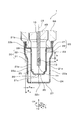
- FIG. 3 is a cross-sectional view of the gas sensor in the first embodiment.
- the partial enlarged view of the gas sensor in FIG. 1 is a schematic diagram of an engine including a gas sensor according to Embodiment 1.
- FIG. 3 is a graph showing the relationship between crank angle, A / F and ⁇ A / F and time in Example 1.
- FIG. The graph showing the relationship between the imbalance value and the direction of a sensor element in Example 1 and Comparative Example 1.
- FIG. 3 is a schematic diagram for explaining the orientation of the sensor element in the first embodiment.
- FIG. 3 is a graph showing a relationship between a detected value variation of an imbalance value and d / c in Example 1. Sectional drawing of the gas sensor in Example 2.
- FIG. 3 is
- the gas sensor of the present invention can be used for air-fuel ratio control in an automobile internal combustion engine.
- it can be suitably used for air-fuel ratio control in a multi-cylinder internal combustion engine.
- Example 1 The gas sensor according to the first embodiment will be described with reference to FIGS.
- the gas sensor 1 of the present example includes a sensor element 10 and a measured gas side cover 20 as shown in FIG.
- the sensor element 10 is formed in a rod shape.
- the longitudinal direction of the sensor element 10 is set as the axial direction Y.
- a central axis CT passing through the center position of the cross section perpendicular to the axial direction Y of the sensor element 10 can be set, and when the axial direction Y is placed on the central axis CT, as shown in FIG.
- a radial radial direction X extending along the orthogonal cross section is set, and a circumferential direction CR is set around the axial direction Y.
- the side of the sensor element 10 on which the detection unit is provided is referred to as the distal end side Y1, and the side opposite to the distal end side is referred to as the proximal end side Y2.
- the sensor element 10 includes a detection unit 11 that detects a specific gas concentration in the gas to be measured.
- the measured gas side cover 20 includes an inner cover 21 that covers the detection unit 11 and an outer cover 22 that covers the inner cover 21 so as to form a gas flow part 30 through which the measured gas flows between the inner cover 21 and the inner cover 21. Have.
- the detection unit 11 is formed with an intake unit 13 that takes in the gas to be measured.
- the gas circulation part 30 has a first gas circulation part 31 and a second gas circulation part 32 between the side wall 21 a of the inner cover 21 and the side wall 22 a of the outer cover 22.
- the 1st gas distribution part 31 is located in the front end side Y1.
- the second gas circulation part 32 is located on the proximal end side Y ⁇ b> 2 with respect to the first gas circulation part 31 and is formed wider than the first gas circulation part 31.
- an inner side wall hole 23 through which the gas to be measured flows is formed at a position facing the second gas circulation portion 32.
- An outer side wall hole 24 through which the gas to be measured flows is formed in the side wall 22a of the outer cover 22 at a position closer to the front end side Y1 than the inner side wall hole 23.
- the distance between the side wall 21a of the inner cover 21 and the side wall 22a of the outer cover 22 in the first gas circulation part 31 is c, and the inner cover 21 is positioned at the position in the axial direction Y of the inner side wall hole 23 in the second gas circulation part 32.
- the relationship d> 1.5c is satisfied.
- the gas sensor 1 is attached to an exhaust system of an internal combustion engine of an automobile and used for air-fuel ratio control of the internal combustion engine.
- it is attached to an exhaust collecting portion of an exhaust manifold in a 4-cylinder engine.
- the sensor element 10 is formed in a rod shape extending in the axial direction Y, includes a detection unit 11 that detects a gas to be measured at the distal end, and an output unit that outputs a detection result of the detection unit 11 at the proximal end. 12 is provided.
- the sensor element 10 is held in an interior 40 a of a cylindrical insulator 40, and the insulator 40 is accommodated in an interior 50 a of a substantially cylindrical housing 50.
- an atmosphere side cover 51 is provided on the base end side Y ⁇ b> 2 of the housing 50.
- An air introduction hole (not shown) is provided on the outer peripheral surface on the base end side of the atmosphere side cover 51.
- a water repellent filter is provided in the air introduction hole. The atmosphere is configured to flow into the atmosphere-side cover 51 from the atmosphere introduction hole through the water repellent filter.
- An air-side atmosphere 52 is formed inside the air-side cover 51.
- the interior 40 a of the insulator 40 has a shape that follows the outer shape of the sensor element 10 from the center in the axial direction Y to the tip end side Y1.
- the sensor element 10 is inserted into the inside 40 a of the insulator 40.
- a space between the sensor element 10 and the insulator 40 is sealed with a sealing glass 43.
- an atmosphere-side insulator 41 is disposed on the base end side Y ⁇ b> 2 of the insulator 40.
- a lead terminal 42 is disposed inside the atmosphere-side insulator 41, and the lead terminal 42 is in contact with the output portion 12 of the sensor element 10 so as to be electrically connected.
- the sensor element 10 is a stacked air-fuel ratio (A / F) detection element.
- a measured gas side cover 20 that covers the detection unit 11 of the sensor element 10 is provided at the front end Y1 of the housing 50.
- the measured gas side cover 20 has a double structure including an inner cover 21 and an outer cover 22.
- an inner side wall hole 23 is provided in the side wall 21 a of the inner cover 21, and an outer side wall hole 24 is provided in the distal end side Y ⁇ b> 1 of the side wall 22 a of the outer cover 22.
- the gas to be measured flows into the inner cover 21 through the inner side wall hole 23 and the outer side wall hole 24.
- the measured gas side atmosphere 25 is formed inside the inner cover 21.
- the inner cover 21 has a substantially cylindrical shape with a bottom, and is open to the proximal end side Y2.
- a diameter-expanded portion 21 b that is expanded along the distal end portion 53 of the housing 50 is formed at the end portion of the inner cover 21 on the proximal end side Y ⁇ b> 2.
- the enlarged diameter portion 21 b is fitted to the distal end portion 53 of the housing 50.
- the inner side wall hole 23 formed in the side wall 21 a of the inner cover 21 is closer to the base end side Y ⁇ b> 2 than the capturing portion 13 provided in the detection unit 11 of the sensor element 10 in the axial direction Y. It is located and opposes the 2nd gas distribution part 32 mentioned below.
- Eight inner side wall holes 23 are provided at equal intervals in the circumferential direction. If the length in the axial direction Y of the capturing portion 13 is a, and the distance from the end of the proximal end Y2 of the capturing portion 13 to the center of the inner side wall hole 23 in the axial direction Y is b, b ⁇ 2a Meet the relationship.
- a bottom hole 26 is formed in the bottom 21c of the inner cover 21, and the gas to be measured that flows into the inner cover 21 from the inner side wall hole 23 flows out through the bottom hole 26. Yes.
- the outer cover 22 has a substantially cylindrical shape with a bottom.
- the end portion 22b on the base end side Y2 of the outer cover 22 that opens to the base end side Y2 has a shape that follows the enlarged diameter portion 21b of the inner cover 21, and is fitted to the enlarged diameter portion 21b. .
- the outer cover 22 covers the inner cover 21.
- a gap is provided between the inner cover 21 and the outer cover 22 except for a portion where the enlarged diameter portion 21b and the end portion 22b are engaged, and a gas flow portion 30 through which the gas to be measured flows is formed. ing.
- the gas circulation part 30 includes a first gas circulation part 31 and a second gas circulation part 32 that are formed between the sidewall 21 a of the inner cover 21 and the sidewall 22 a of the outer cover 22. Furthermore, a third gas circulation part 33 formed between the bottom part 21 c of the inner cover 21 and the bottom part 22 c of the outer cover 22 is provided. A part of the second gas circulation part 32 faces the inner side wall hole 23. The first gas circulation part 31 is located closer to the front end Y1 than the second gas circulation part 32.
- an outer side wall hole 24 through which a gas to be measured flows is formed in the side wall 22a of the outer cover 22 at a position closer to the tip side Y1 than the inner side wall hole 23.
- a bottom hole 27 through which the gas to be measured flows is formed in the bottom 22c of the outer cover 22. The gas to be measured flows into the outer cover 22 through the outer side wall hole 24 and the bottom hole 27 and flows out from the outer cover 22 to the outside.
- the distance between the side wall 21 a of the inner cover 21 and the side wall 22 a of the outer cover 22 in the first gas circulation part 31 (the width of the first gas circulation part 31 in the radial direction X perpendicular to the axial direction Y).
- C and the distance between the side wall 21a of the inner cover 21 and the side wall 22a of the outer cover 22 at the position in the axial direction Y of the inner side wall hole 23 in the second gas circulation part 32 (the second gas circulation part 32 in the radial direction X). If the width is d, the relationship of d> 1.5c is satisfied.
- the gas sensor 1 of this example is provided upstream of the catalyst unit 103 in the exhaust collecting unit 101 of the four-cylinder engine 100. Exhaust gas discharged from the four cylinders 102 is collected in the exhaust collecting unit 101 and becomes collective exhaust.
- the gas sensor 1 is configured to detect a specific gas concentration in the gas to be measured from the collective exhaust and detect A / F.
- the imbalance value detection test method and the imbalance determination method are shown below.
- the exhaust of one cylinder among the four cylinders 102 is changed to the rich side so that an A / F imbalance (variation) occurs between the cylinders 102.
- the gas sensor 1 detects A / F every 4 ms.
- a difference ⁇ A / F from the immediately preceding A / F value is calculated from the detected A / F.
- the A / F detected by the gas sensor 1 changes periodically every one engine cycle (crank angle 720CA). Then, for each cycle, the average value ( ⁇ A / F (+) average value, sign 401) of ⁇ A / F being positive (+) and the average value ( ⁇ A / F) of ⁇ A / F being negative ( ⁇ ) / F ( ⁇ ) average value, sign 402) is calculated. Next, the maximum value (average one-time differential value) of ⁇ A / F (+) average value and the minimum value (average one-time differential value) of ⁇ A / F ( ⁇ ) averaged over 100 cycles are extracted, Each absolute value is used as an imbalance value. The imbalance value is compared with the reference value, and when the imbalance value is higher than the reference value, it is determined as abnormal, and when it is lower, it is determined as normal.
- the relationship between the orientation of the sensor element 10 and the imbalance value with respect to the exhaust flow direction is shown in FIG. 6, and the rate of change of the imbalance value is shown. 7 shows.
- the distance between the side wall 21a of the inner cover 21 and the side wall 22a of the outer cover 22 in the first gas flow part 31 is c1, and the second gas flow.
- the distance between the side wall 21a of the inner cover 21 and the side wall 22a of the outer cover 22 at the position in the axial direction Y of the inner side wall hole 23 in the portion 32 is d1, and the length in the axial direction Y of the intake portion 13 is a1.
- the direction of the sensor element 10 with respect to the exhaust flow direction is the exhaust manifold (exhaust collecting portion 101) as shown in FIGS. 8A, 8B, 8C, and 8D, respectively.
- the capturing part 13 is a diffusion resistance layer made of a porous layer, and is configured such that the gas to be measured reaches the measurement side electrode 15 via the capturing part 13.
- the change rate (%) of the imbalance value shown in FIG. 7 is a value obtained by subtracting the minimum value from the maximum value of the imbalance value among the respective directions (four directions) of the sensor element 10 with respect to the exhaust flow direction. Dividing by the average imbalance value in four directions and multiplying by 100.
- the gas sensor of Example 1 is larger than the imbalance value detected by the samples 1 to 3 of the gas sensor 900 of Comparative Example 1.
- the imbalance value detected by one sample 1 to 3 was larger.
- the rate of change of the imbalance value is large depending on the direction of the sensor element 10 with respect to the exhaust flow direction, and the sample 1 of the gas sensor 1 of the first embodiment. From 3 to 3, the rate of change of the imbalance value was small.
- the detected imbalance value is larger in the gas sensor 1 of the first embodiment than the gas sensor 900 of the first comparative example, and the detected value of the imbalance value varies depending on the direction of the sensor element 10 with respect to the exhaust flow direction. This indicates that the detection accuracy of the imbalance value is excellent.
- the relationship between the average imbalance value in four directions and b / a when b / a is changed in the configuration of the gas sensor 1 of Example 1 is shown in FIG.
- the relationship between the balance value detection value variation) and d / c is shown in FIG.
- d / c> 1.5 that is, d> 1.5c
- fills d> 1.5c it was confirmed that the detection accuracy is improved.
- the second gas circulation part 32 is formed to be sufficiently wider than the first gas circulation part 31.
- the gas to be measured that has flowed from the outer side wall hole 24 provided on the front end side Y1 of the outer cover 22 is rectified in the first gas circulation portion 31 that is formed to be narrow and then formed to have a wide width. It distribute
- the gas to be measured flowing from the outer side wall hole 24 smoothly flows through the first gas circulation part 31 and the second gas circulation part 32 and flows into the inner cover 21 from the inner side wall hole 23. .
- the taking-in part 13 and the inner side wall hole 23 are arrange
- the gas to be measured that has flowed into the inner cover from the inner side wall hole 23 easily reaches the intake portion 13. That is, according to the gas sensor 1, the gas to be measured flows smoothly into the inner cover 21 and easily reaches the intake portion 13, so that the detection accuracy of the sensor element 10 can be improved.
- the sensor element 10 since the sensor element 10 is a laminated type, the sensor element 10 can be arranged in various directions with respect to the exhaust flow direction P as shown in FIGS. 8 (A) to 8 (D).
- the imbalance detectability of the gas sensor 1 of the present example has little variation depending on the orientation of the sensor element 10 with respect to the exhaust flow direction P, according to the gas sensor 1 of the present example, when the stacked sensor element 10 is employed. Thus, the detection accuracy of the imbalance value can be further improved.
- the present invention may be applied to a multi-cylinder engine such as a 6-cylinder or 8-cylinder engine that is required to improve imbalance detection.
- a multi-cylinder engine such as a 6-cylinder or 8-cylinder engine that is required to improve imbalance detection.
- OBD On Board Diagnostics
- Example 2 A gas sensor according to Example 2 is shown in FIG. As shown in FIG. 11, in the gas sensor 1 of this example, the inner side wall hole 23 is formed on the proximal end side Y2 as compared with the case of the first embodiment. Other configurations are the same as those described in the first embodiment.
- the gas sensor 1 of this example also satisfies the relationship of b ⁇ 2a, d> 1.5c. For this reason, the same effect as the case of Example 1 can be produced.
Landscapes
- Chemical & Material Sciences (AREA)
- Life Sciences & Earth Sciences (AREA)
- Health & Medical Sciences (AREA)
- Physics & Mathematics (AREA)
- Chemical Kinetics & Catalysis (AREA)
- Electrochemistry (AREA)
- Molecular Biology (AREA)
- Analytical Chemistry (AREA)
- Biochemistry (AREA)
- General Health & Medical Sciences (AREA)
- General Physics & Mathematics (AREA)
- Immunology (AREA)
- Pathology (AREA)
- Measuring Oxygen Concentration In Cells (AREA)
Abstract
ガスセンサ(1)は、センサ素子(10)と、内側カバー(21)及び外側カバー(22)を備えた被測定ガス側カバー(20)とを備える。内側カバー(21)の側壁(21a)と外側カバー(22)の側壁(22a)との間には、センサ先端側(Y1)に第1ガス流通部(31)が形成され、センサ基端側(Y2)に第2ガス流通部(32)が形成されている。センサ素子(10)の取り込み部(13)の軸方向Yの長さをa、内側カバー(21)において第2ガス流通部(32)に対向する位置に形成された内側側壁孔(23)と取り込み部(13)との軸方向Yにおける距離をbとしたとき、b<2aの関係を満たす。第1ガス流通部(31)における側壁(21a)と側壁(22a)との間の距離をcとし、第2ガス流通部(32)における内側側壁孔(23)の軸方向Yの位置に対応した部分での側壁(21a)と側壁(22a)との間の距離をdとしたとき、d>1.5cの関係を満たす。
Description
本発明は、被測定ガスに含まれる特定成分のガスの濃度を検知するガスセンサに関する。
従来、自動車等、多くの内燃機関において空燃比制御がなされている。この空燃比制御には、排ガスとしての被測定ガスに含まれる特定成分のガス(特定ガス)の濃度を検出するガスセンサが用いられている。このガスセンサとして、特許文献1に開示の構成が知られている。
この特許文献1には、先端側に被測定ガス中の特定ガスを検出する検出部を備える棒状のセンサ素子を有するガスセンサが開示されている。このガスセンサは、センサ素子の検出部に設けられた、被測定ガス(排ガス)が流通する孔を有する二重構造のカバーを有する。このカバーの孔は、センサ素子の被水や被毒を抑制するため、被測定ガスの流れがセンサ素子の検出部に直接当たらないように所定の形状で所定の位置に設けられている。
近年、内燃機関における空燃比制御の精度向上が求められている。例えば、多気筒の内燃機関では、各気筒の排気ポートは排気マニホールドの枝管を介して排気集合部に連結されており、当該排気集合部にガスセンサが設けられている。このガスセンサによって集合排気から被測定ガス中の特定ガスの濃度を検出して空燃比(A/F)を検出するように構成されている。この構成において、インジェクタの故障などによって一つの気筒から排気がリッチ側に変動した場合には、当該気筒の空燃比(A/F)が理論空燃比からずれる。このため、気筒間にA/Fのインバランス(ばらつき、不均衡、又は不均一性を示す)が発生する。かかるA/Fのインバランス値(インバランスの程度を示す値)を検出することにより各気筒に発生した異常を検出することができる。ガスセンサによるA/Fのインバランス値の検出精度を向上することによって、空燃比制御をより高精度に行うことができる。しかしながら、従来の構成では、センサ素子の検出部を覆うカバーがセンサ素子の被水や被毒を抑制するように構成されている。このため、被測定ガスがカバー内を円滑に流通できずに検出部に到達しにくい場合がある。この場合には、十分高い検出精度が得られないことから、改良の余地がある。
本発明は、かかる背景に鑑みてなされたもので、内燃機関の空燃比制御をより高精度に行うために使用できるガスセンサを提供しようとするものである。
本発明の一態様に係るガスセンサは、被測定ガス中に含まれる特定ガスの濃度を検出する検出部を備えるセンサ素子と、上記検出部を覆う内側カバーと、該内側カバーとの間に被測定ガスが流通するガス流通部を形成するように上記内側カバーを覆う外側カバーとからなる被測定ガス側カバーと、を備える。上記検出部には、被測定ガスを取り込む取り込み部が形成されており、上記ガス流通部は、上記内側カバーの側壁と上記外側カバーの側壁との間において、先端側に位置する第1ガス流通部と、該第1ガス流通部よりも基端側に位置するとともに該第1ガス流通部よりも幅広に形成される第2ガス流通部とを有している。上記内側カバーの側壁には、上記第2ガス流通部に対向する位置に被測定ガスが流通する内側側壁孔が形成されている。上記外側カバーの側壁には、上記内側側壁孔よりも先端側の位置に、被測定ガスが流通する外側側壁孔が形成されている。上記センサ素子の軸方向における取り込み部の長さをaとし、上記軸方向における上記内側側壁孔と上記取り込み部との距離をbとしたとき、b<2aの関係を満たす。さらに、上記第1ガス流通部における上記内側カバーの側壁と上記外側カバーの側壁との距離をcとし、上記第2ガス流通部における上記内側側壁孔の上記軸方向の位置での上記内側カバーの側壁と上記外側カバーの側壁との距離をdとしたとき、d>1.5cの関係を満たす。
上記ガスセンサにおいては、上記第1ガス流通部における上記内側カバーの側壁と上記外側カバーの側壁との距離cと、上記第2ガス流通部における上記内側側壁孔と上記外側カバーの側壁との距離dとが、d>1.5cを満たしている。同時に、第2ガス流通部は第1ガス流通部よりも十分に幅広に形成されている。これにより、外側カバーの先端側に設けられた外側側壁孔から流入してきた被測定ガスが、幅が狭く形成された第1ガス流通部において整流化される。この整流化の後、被測定ガスは、幅が広く形成された第2ガス流通部に流通する。その結果、外側側壁孔から流入してきた被測定ガスが第1ガス流通部及び第2ガス流通部を円滑に流通して、内側側壁孔から内側カバー内に流入する。上記取り込み部の軸方向の長さa、上記内側側壁孔と上記取り込み部との軸方向における距離bがb<2aを満たす。これにより、取り込み部と内側側壁孔とが互いに十分近接して配置される。このため、内側側壁孔から内側カバー内に流入してきた被測定ガスが取り込み部に到達しやすくなる。すなわち、上記ガスセンサによれば、被測定ガスが内側カバー内に円滑に流入されるとともに、取り込み部に到達しやすいため、センサ素子の検出精度を向上することができる。
以上のごとく、本発明によれば、内燃機関の空燃比制御をより高精度に行うために使用可能なガスセンサを提供ことができる。
添付図面において、
実施例1における、ガスセンサの断面図。
図1における、ガスセンサの一部拡大図。
実施例1におけるガスセンサを備えるエンジンの模式図。
実施例1における、クランクアングル、A/F及びΔA/Fと時間との関係を表したグラフ。
比較例1における、ガスセンサの一部拡大図。
実施例1及び比較例1における、インバランス値とセンサ素子の向きとの関係を表したグラフ。
実施例1及び比較例1における、センサ素子の向きによるインバランス値の変化率を表したグラフ。
実施例1における、センサ素子の向きを説明する模式図。
実施例1における、インバランス値とb/aとの関係を表したグラフ。
実施例1における、インバランス値の検出値ばらつきとd/cとの関係を表したグラフ。
実施例2における、ガスセンサの断面図。
本発明のガスセンサは、自動車の内燃機関における空燃比制御に使用することができる。中でも多気筒の内燃機関における空燃比制御に好適に使用することができる。
(実施例1)
本実施例1に係るガスセンサにつき、図1~図10を用いて説明する。
本実施例1に係るガスセンサにつき、図1~図10を用いて説明する。
本例のガスセンサ1は、図1に示すように、センサ素子10及び被測定ガス側カバー20を備える。
センサ素子10は、棒状に形成されている。このため、このセンサ素子10の長手方向を軸方向Yとして設定する。この場合、センサ素子10の軸方向Yに直交する断面の中心位置を通る中心軸CTを設定でき、その中心軸CTに軸方向Yを置くと、図1に示すように、その軸方向Yから上記直交断面に沿って伸びる放射状の径方向Xが設定され、さらに軸方向Yの周りに周方向CRが設定される。さらに、本実施例では、センサ素子10の検出部が設けられる側を先端側Y1とし、先端側と反対側を基端側Y2と呼んでいる。
センサ素子10は、被測定ガス中の特定ガス濃度を検出する検出部11を備える。被測定ガス側カバー20は、検出部11を覆う内側カバー21と、内側カバー21との間に被測定ガスが流通するガス流通部30を形成するように内側カバー21を覆う外側カバー22とを有する。
センサ素子10は、被測定ガス中の特定ガス濃度を検出する検出部11を備える。被測定ガス側カバー20は、検出部11を覆う内側カバー21と、内側カバー21との間に被測定ガスが流通するガス流通部30を形成するように内側カバー21を覆う外側カバー22とを有する。
図2に示すように、検出部11には、被測定ガスを取り込む取り込み部13が形成されている。
ガス流通部30は、内側カバー21の側壁21aと外側カバー22の側壁22aとの間において、第1ガス流通部31と第2ガス流通部32とを有している。第1ガス流通部31は先端側Y1に位置する。第2ガス流通部32は、第1ガス流通部31よりも基端側Y2に位置するとともに、該第1ガス流通部31よりも幅広に形成される。
内側カバー21の側壁21aには、第2ガス流通部32に対向する位置に被測定ガスが流通する内側側壁孔23が形成されている。
外側カバー22の側壁22aには、内側側壁孔23よりも先端側Y1の位置に、被測定ガスが流通する外側側壁孔24が形成されている。
取り込み部13の軸方向Yの長さをaとし、内側側壁孔23と取り込み部13との軸方向Yにおける距離をbとしたとき、b<2aの関係を満たしている。
第1ガス流通部31における内側カバー21の側壁21aと外側カバー22の側壁22aとの距離をcとし、第2ガス流通部32における内側側壁孔23の軸方向Yの位置での内側カバー21の側壁21aと外側カバー22の側壁22aとの距離をdとしたとき、d>1.5cの関係を満たしている。
以下、本例のガスセンサ1について詳述する。
ガスセンサ1は、一例として、自動車の内燃機関の排気系に取付けられて、内燃機関の空燃比制御に利用されるものである。本例では、4気筒のエンジンにおける排気マニホールドの排気集合部に取り付けられている。
図1に示すように、センサ素子10は、軸方向Yに延びる棒状に形成され、先端に被測定ガスを検出する検出部11を備え、基端に検出部11の検出結果を出力する出力部12を備える。センサ素子10は筒状のインシュレータ40の内部40aに保持されており、インシュレータ40は略筒状のハウジング50の内部50aに収納されている。また、ハウジング50の基端側Y2には大気側カバー51が設けてある。大気側カバー51の基端側の外周面には図示しない大気導入孔が備えられている。また、大気導入孔には撥水フィルタが設けられている。大気は、大気導入孔から当該撥水フィルタを介して大気側カバー51内に流入されるように構成されている。大気側カバー51の内部に大気側雰囲気52が形成されている。
図1に示すように、インシュレータ40の内部40aは、軸方向Yにおける中央から先端側Y1においてセンサ素子10の外形に沿う形状を成している。インシュレータ40の内部40aにはセンサ素子10が挿通されている。センサ素子10とインシュレータ40との間は封止ガラス43によって封止されている。
図1に示すように、インシュレータ40の基端側Y2には大気側インシュレータ41が配置されている。大気側インシュレータ41の内部にはリード端子42が配置され、リード端子42はセンサ素子10の出力部12と電気的導通が取れるように接触している。なお、本例では、センサ素子10は積層型の空燃比(A/F)検出用素子である。
図1に示すように、ハウジング50の先端側Y1には、センサ素子10の検出部11を覆う被測定ガス側カバー20が設けられる。被測定ガス側カバー20は、内側カバー21と外側カバー22とからなる二重構造を有している。図2に示すように、内側カバー21の側壁21aには内側側壁孔23が設けられており、外側カバー22の側壁22aの先端側Y1には外側側壁孔24が設けられている。内側側壁孔23及び外側側壁孔24を介して、被測定ガスが内側カバー21の内部に流入するように構成されている。これにより、内側カバー21の内部に被測定ガス側雰囲気25が形成されている。
図2に示すように、内側カバー21は有底の略円筒形を成しており、基端側Y2に開口している。内側カバー21における基端側Y2の端部には、ハウジング50の先端部53に沿って拡径された拡径部21bが形成されている。そして、当該拡径部21bがハウジング50の先端部53に嵌合されている。これにより、内側カバー21の内部に、センサ素子10の検出部11が位置することとなる。
図2に示すように、内側カバー21の側壁21aに形成されている内側側壁孔23は、軸方向Yにおいて、センサ素子10の検出部11に設けられた取り込み部13よりも基端側Y2に位置しており、後述の第2ガス流通部32に対向している。内側側壁孔23は周方向に等間隔に8個設けられている。そして、取り込み部13の軸方向Yの長さをaとし、軸方向Yにおいて、取り込み部13の基端側Y2の端部から内側側壁孔23の中心までの距離をbとすると、b<2aの関係を満たしている。なお、内側カバー21の底部21cには底部孔26が形成されており、内側側壁孔23から内側カバー21の内部に流入した被測定ガスが当該底部孔26を介して流出するように構成されている。
図2に示すように、外側カバー22は有底の略円筒状を成している。基端側Y2に開口している外側カバー22における基端側Y2の端部22bは、内側カバー21の拡径部21bに沿った形状をなしており、拡径部21bに嵌合している。これにより、外側カバー22が内側カバー21を覆っている。内側カバー21と外側カバー22との間には、拡径部21bと端部22bとの係合箇所を除いて、間隙が設けられており、被測定ガスが流通するガス流通部30が形成されている。ガス流通部30は、内側カバー21の側壁21aと外側カバー22の側壁22aとの間に形成される第1ガス流通部31及び第2ガス流通部32を備える。さらに、内側カバー21の底部21cと外側カバー22の底部22cとの間に形成される第3ガス流通部33を備える。第2ガス流通部32の一部は内側側壁孔23に対向している。第1ガス流通部31は、第2ガス流通部32よりも先端側Y1に位置している。
図2に示すように、外側カバー22の側壁22aには、内側側壁孔23よりも先端側Y1の位置に、被測定ガスが流通する外側側壁孔24が形成されている。また、外側カバー22の底部22cには被測定ガスが流通する底部孔27が形成されている。被測定ガスは、外側側壁孔24及び底部孔27を介して外側カバー22の内部に流入し、外側カバー22の内部から外部へ流出するように構成されている。
図2に示すように、第1ガス流通部31における内側カバー21の側壁21aと外側カバー22の側壁22aとの距離(軸方向Yに直交する径方向Xにおける第1ガス流通部31の幅)をcとし、第2ガス流通部32における内側側壁孔23の軸方向Yの位置での内側カバー21の側壁21aと外側カバー22の側壁22aとの距離(径方向Xにおける第2ガス流通部32の幅)をdとすると、d>1.5cの関係を満たしている。
図3に示すように、本例のガスセンサ1は、4気筒エンジン100の排気集合部101において、触媒部103よりも上流側に設けられている。4つの気筒102から排出された排気は、排気集合部101で集合されて集合排気となる。ガスセンサ1は、当該集合排気から被測定ガス中の特定ガス濃度を検出し、A/Fを検出するように構成されている。
次に、インバランス値の検出試験方法、及びインバランスの判定方法を以下に示す。まず、4つ気筒102のうち一つの気筒の排気をリッチ側に変動させて、気筒102間にA/Fのインバランス(ばらつき)が発生する状態にする。そして、図4に示すように、ガスセンサ1によって、4msごとにA/Fを検出する。さらに、検出したA/Fから、直前のA/F値との差分ΔA/Fを算出する。
図4に示すように、ガスセンサ1により検出されるA/Fは、概ね1エンジンサイクル(クランクアングル720CA)ごとに周期的に変動することとなる。そして、サイクルごとにΔA/Fが正(+)である値の平均値(ΔA/F(+)平均値、符号401)と、ΔA/Fが負(-)である値の平均値(ΔA/F(-)平均値、符号402)を算出する。次に、100サイクル間におけるΔA/F(+)平均値の最大値(平均1回微分値)と、ΔA/F(-)平均値の最小値(平均1回微分値)とを抽出し、それぞれの絶対値をインバランス値とする。当該インバランス値と基準値とを比較して、インバランス値が基準値を上回っている場合には異常と判定し、下回っている場合には正常と判定する。
実施例1のガスセンサ1及び、図5に示す比較例1のガスセンサ900について、排気流れ方向に対するセンサ素子10の向きとインバランス値との関係を図6に示し、インバランス値の変化率を図7に示す。比較例1のガスセンサ900は、図5に示すように、ガスセンサ900において、第1ガス流通部31における内側カバー21の側壁21aと外側カバー22の側壁22aとの距離をc1とし、第2ガス流通部32における内側側壁孔23の軸方向Yの位置での内側カバー21の側壁21aと外側カバー22の側壁22aとの距離をd1とし、取り込み部13の軸方向Yの長さをa1とし、内側側壁孔23と取り込み部13との軸方向Yにおける距離をb1としたとき、d1=c1、b1>2a1の関係を満たしている。
上述の排気流れ方向に対するセンサ素子10の向きとは、図8(A)、図8(B)、図8(C)、図8(D)にそれぞれ示すように、排気マニホールド(排気集合部101、図3参照)内の排気流れ方向Pに対するセンサ素子10のヒータ面14の法線とのなす角(0°、90°、180°及び270°)をいうものとする。取り込み部13は多孔質層からなる拡散抵抗層であって、取り込み部13を介して被測定ガスが測定側電極15に到達するように構成されている。また、図7に示したインバランス値の変化率(%)は、排気流れ方向に対するセンサ素子10の各向き(4方向)のうち、インバランス値の最大値から最小値を差し引いた値を、4方向における平均インバランス値で除して100倍したものである。
図6に示すように、排気流れ方向に対するセンサ素子10の向きがいずれの場合も、比較例1のガスセンサ900のサンプル1~3によって検出されたインバランス値の大きさよりも、実施例1のガスセンサ1のサンプル1~3によって検出されたインバランス値の大きさの方が大きくなっていた。さらに、図7に示すように、比較例1のガスセンサ900のサンプル1~3では、排気流れ方向に対するセンサ素子10の向きによってインバランス値の変化率が大きく、実施例1のガスセンサ1のサンプル1~3では当該インバランス値の変化率が小さくなっていた。これらの結果から、比較例1のガスセンサ900に比べて、実施例1のガスセンサ1では、検出されるインバランス値が大きく、排気流れ方向に対するセンサ素子10の向きによるインバランス値の検出値のばらつきが少ないことから、インバランス値の検出精度に優れていることが示された。
さらに、実施例1のガスセンサ1の構成においてb/aを変化させた場合の、4方向における平均インバランス値とb/aとの関係を図9に示した。ガスセンサにより検出されるインバランス値は大きい方が検出精度を向上させやすい。具体的にはガスセンサ1により検出されるインバランス値が0.35よりも大きければ、検出精度の向上が十分に図られる。図9に示すように、b/a<2、すなわちb<2aであれば、検出されるインバランス値が0.35よりも大きくなっていた。これにより、b<2aを満たす本例のガスセンサ1によれば検出精度の向上が図られることが確認された。
さらに、実施例1のガスセンサ1の構成においてd/cを変化させた場合の、センサ素子10の各向き(4方向)における検出されるインバランス値の最大値から最小値を差し引いた値(インバランス値の検出値ばらつき)とd/cとの関係を図10に示した。ガスセンサにより検出されるインバランス値の検出値のばらつきは小さい方が検出精度を向上させやすい。図10に示すように、d/c>1.5、すなわちd>1.5cのとき、センサ素子10の向きによるインバランス値の検出値ばらつきが小さくなっていた。これにより、d>1.5cを満たす本例のガスセンサ1によれば、検出精度の向上が図られることが確認された。
本例のガスセンサ1によれば、d>1.5cを満たすように構成されていることから、第2ガス流通部32は第1ガス流通部31よりも十分幅広に形成されている。これにより、外側カバー22の先端側Y1に設けられた外側側壁孔24から流入してきた被測定ガスが、幅が狭く形成された第1ガス流通部31において整流化された後、幅が広く形成された第2ガス流通部32に流通することとなる。その結果、外側側壁孔24から流入してきた被測定ガスが第1ガス流通部31及び第2ガス流通部32を円滑に流通して、内側側壁孔23から内側カバー21内に流入することとなる。そして、b<2aを満たすように構成されていることから、取り込み部13と内側側壁孔23とが互いに十分近接して配置されている。これにより、内側側壁孔23から内側カバー内に流入してきた被測定ガスが取り込み部13に到達しやすくなる。すなわち、ガスセンサ1によれば、被測定ガスが内側カバー21内を円滑に流入するとともに、取り込み部13に到達しやすいため、センサ素子10の検出精度を向上することができる。
本例では、センサ素子10は積層型であるため、図8(A)~図8(D)に示すように、センサ素子10は排気流れ方向Pに対して様々な向きで配置されうる。しかし、本例のガスセンサ1のインバランス検出性は、排気流れ方向Pに対するセンサ素子10の向きによってばらつきが少ないため、本例のガスセンサ1によれば、積層型のセンサ素子10を採用する場合に、インバランス値の検出精度を一層向上させることができる。
本例では、4気筒のエンジンに適用したがこれに限らない。例えば、インバランス検出性の向上が求められている6気筒や8気筒等の多気筒のエンジンに適用してもよい。これにより、従来、これらの多気筒エンジンにおいても、インバランス検出精度を向上させることができる。そのため、インバランス量が少なくても十分検出できることから、6気筒や8気筒等の多気筒のエンジンにおいてもインバランスに対する自己診断機能(OBD(On Board Diagnostics))へ容易に適合できる。
以上のごとく、本例によれば、内燃機関の空燃比制御をより高精度に行うために使うことができるガスセンサを提供することができる。
(実施例2)
実施例2に係るガスセンサを図11に示す。
図11に示すように、本例のガスセンサ1は、実施例1の場合に比べて、内側側壁孔23が基端側Y2に形成されている。これ以外の構成は、実施例1に記載のものと同様である。本例のガスセンサ1においても、b<2a、d>1.5cの関係を満たしている。このため、実施例1の場合と同様の作用効果を奏することができる。
実施例2に係るガスセンサを図11に示す。
図11に示すように、本例のガスセンサ1は、実施例1の場合に比べて、内側側壁孔23が基端側Y2に形成されている。これ以外の構成は、実施例1に記載のものと同様である。本例のガスセンサ1においても、b<2a、d>1.5cの関係を満たしている。このため、実施例1の場合と同様の作用効果を奏することができる。
1 ガスセンサ
10 センサ素子
11 検出部
13 取り込み部
20 被測定ガス側カバー
21 内側カバー
22 外側カバー
23 内側側壁孔
24 外側側壁孔
30 ガス流通部
31 第1ガス流通部
32 第2ガス流通部
10 センサ素子
11 検出部
13 取り込み部
20 被測定ガス側カバー
21 内側カバー
22 外側カバー
23 内側側壁孔
24 外側側壁孔
30 ガス流通部
31 第1ガス流通部
32 第2ガス流通部
Claims (2)
- 被測定ガスに含まれる特定ガスの濃度を検出する検出部(11)を備えるセンサ素子(10)と、
上記検出部(11)を覆う内側カバー(21)と、該内側カバー(21)との間に被測定ガスが流通するガス流通部(30)を形成するように上記内側カバー(21)を覆う外側カバー(22)とからなる被測定ガス側カバー(20)と、を備え、
上記検出部(11)には、被測定ガスを取り込む取り込み部(13)が形成されており、
上記ガス流通部(30)は、上記内側カバー(21)の側壁(21a)と上記外側カバー(22)の側壁(22a)との間において、先端側(Y1)に位置する第1ガス流通部(31)と、該第1ガス流通部(31)よりも基端側(Y2)に位置するとともに該第1ガス流通部(31)よりも幅広に形成される第2ガス流通部(32)とを有しており、
上記内側カバー(21)の側壁(21a)には、上記第2ガス流通部(32)に対向する位置に被測定ガスが流通する内側側壁孔(23)が形成されており、
上記外側カバー(22)の側壁(22a)には、上記内側側壁孔(23)よりも先端側(Y1)の位置に、被測定ガスが流通する外側側壁孔(24)が形成されており、
上記取り込み部(13)の軸方向(Y)の長さをaとし、上記内側側壁孔(23)と上記取り込み部(13)との軸方向(Y)における距離をbとしたとき、b<2aの関係を満たすとともに、
上記第1ガス流通部(31)における上記内側カバー(21)の側壁(21a)と上記外側カバー(22)の側壁(22a)との距離をcとし、上記第2ガス流通部(32)における上記内側側壁孔(23)の上記軸方向(Y)の位置での上記内側カバー(21)の側壁(21a)と上記外側カバー(22)の側壁(22a)との距離をdとしたとき、d>1.5cの関係を満たすことを特徴とするガスセンサ。 - 上記センサ素子(10)は、積層型であることを特徴とする請求項1に記載のガスセンサ(1)。
Priority Applications (1)
| Application Number | Priority Date | Filing Date | Title |
|---|---|---|---|
| DE112015002797.1T DE112015002797B4 (de) | 2014-06-13 | 2015-06-11 | Gassensor zum Erfassen einer Gaskonzentration |
Applications Claiming Priority (2)
| Application Number | Priority Date | Filing Date | Title |
|---|---|---|---|
| JP2014-122671 | 2014-06-13 | ||
| JP2014122671A JP6458364B2 (ja) | 2014-06-13 | 2014-06-13 | ガスセンサ |
Publications (1)
| Publication Number | Publication Date |
|---|---|
| WO2015190545A1 true WO2015190545A1 (ja) | 2015-12-17 |
Family
ID=54833633
Family Applications (1)
| Application Number | Title | Priority Date | Filing Date |
|---|---|---|---|
| PCT/JP2015/066840 Ceased WO2015190545A1 (ja) | 2014-06-13 | 2015-06-11 | ガスの濃度を検知するガスセンサ |
Country Status (3)
| Country | Link |
|---|---|
| JP (1) | JP6458364B2 (ja) |
| DE (1) | DE112015002797B4 (ja) |
| WO (1) | WO2015190545A1 (ja) |
Families Citing this family (1)
| Publication number | Priority date | Publication date | Assignee | Title |
|---|---|---|---|---|
| JP6623963B2 (ja) * | 2016-07-27 | 2019-12-25 | 株式会社デンソー | ガスセンサ |
Citations (2)
| Publication number | Priority date | Publication date | Assignee | Title |
|---|---|---|---|---|
| JP2007017453A (ja) * | 2001-02-28 | 2007-01-25 | Denso Corp | ガスセンサ |
| JP2012242284A (ja) * | 2011-05-20 | 2012-12-10 | Ngk Spark Plug Co Ltd | ガスセンサ素子の製造方法 |
Family Cites Families (2)
| Publication number | Priority date | Publication date | Assignee | Title |
|---|---|---|---|---|
| JP4124135B2 (ja) | 2004-02-13 | 2008-07-23 | 株式会社デンソー | ガスセンサ |
| JP5765394B2 (ja) | 2012-11-20 | 2015-08-19 | 株式会社デンソー | ガスセンサ |
-
2014
- 2014-06-13 JP JP2014122671A patent/JP6458364B2/ja active Active
-
2015
- 2015-06-11 WO PCT/JP2015/066840 patent/WO2015190545A1/ja not_active Ceased
- 2015-06-11 DE DE112015002797.1T patent/DE112015002797B4/de active Active
Patent Citations (2)
| Publication number | Priority date | Publication date | Assignee | Title |
|---|---|---|---|---|
| JP2007017453A (ja) * | 2001-02-28 | 2007-01-25 | Denso Corp | ガスセンサ |
| JP2012242284A (ja) * | 2011-05-20 | 2012-12-10 | Ngk Spark Plug Co Ltd | ガスセンサ素子の製造方法 |
Also Published As
| Publication number | Publication date |
|---|---|
| DE112015002797T5 (de) | 2017-03-16 |
| JP2016003887A (ja) | 2016-01-12 |
| JP6458364B2 (ja) | 2019-01-30 |
| DE112015002797B4 (de) | 2024-10-10 |
Similar Documents
| Publication | Publication Date | Title |
|---|---|---|
| JP4131242B2 (ja) | ガスセンサ | |
| US10866207B2 (en) | Exhaust gas sensor | |
| US9945312B2 (en) | Abnormality diagnosis device for exhaust gas sensor | |
| US8214176B2 (en) | Exhaust gas sensor abnormality diagnostic device | |
| JP5765394B2 (ja) | ガスセンサ | |
| CN104823044B (zh) | 气体传感器 | |
| JP5206877B2 (ja) | 内燃機関の空燃比気筒間インバランス判定装置 | |
| JP4765865B2 (ja) | ガスセンサ | |
| CN106662547B (zh) | 包括传感器元件、壳体以及元件罩的气体传感器 | |
| US9513252B2 (en) | Gas sensor | |
| JP6233207B2 (ja) | ガスセンサ | |
| JP6458364B2 (ja) | ガスセンサ | |
| JP4647393B2 (ja) | 空燃比センサの異常診断装置 | |
| JP6512033B2 (ja) | ガスセンサ取付構造 | |
| JP2014137004A (ja) | 内燃機関の制御装置 | |
| JP4788498B2 (ja) | ガスセンサ | |
| JP2007271517A (ja) | ガスセンサ | |
| JP5360289B2 (ja) | 内燃機関の空燃比気筒間インバランス判定装置 | |
| JP6499494B2 (ja) | 空燃比センサ、及びそれを用いたインバランス判定システム | |
| JP2014005743A (ja) | 気筒間空燃比ばらつき異常検出装置 |
Legal Events
| Date | Code | Title | Description |
|---|---|---|---|
| 121 | Ep: the epo has been informed by wipo that ep was designated in this application |
Ref document number: 15806396 Country of ref document: EP Kind code of ref document: A1 |
|
| WWE | Wipo information: entry into national phase |
Ref document number: 112015002797 Country of ref document: DE |
|
| 122 | Ep: pct application non-entry in european phase |
Ref document number: 15806396 Country of ref document: EP Kind code of ref document: A1 |