WO2015190186A1 - 内視鏡システム、内視鏡システムの作動方法 - Google Patents
内視鏡システム、内視鏡システムの作動方法 Download PDFInfo
- Publication number
- WO2015190186A1 WO2015190186A1 PCT/JP2015/062830 JP2015062830W WO2015190186A1 WO 2015190186 A1 WO2015190186 A1 WO 2015190186A1 JP 2015062830 W JP2015062830 W JP 2015062830W WO 2015190186 A1 WO2015190186 A1 WO 2015190186A1
- Authority
- WO
- WIPO (PCT)
- Prior art keywords
- image
- information
- angle
- unit
- view
- Prior art date
Links
Images


Classifications
-
- A—HUMAN NECESSITIES
- A61—MEDICAL OR VETERINARY SCIENCE; HYGIENE
- A61B—DIAGNOSIS; SURGERY; IDENTIFICATION
- A61B1/00—Instruments for performing medical examinations of the interior of cavities or tubes of the body by visual or photographical inspection, e.g. endoscopes; Illuminating arrangements therefor
- A61B1/00002—Operational features of endoscopes
- A61B1/00004—Operational features of endoscopes characterised by electronic signal processing
- A61B1/00009—Operational features of endoscopes characterised by electronic signal processing of image signals during a use of endoscope
-
- A—HUMAN NECESSITIES
- A61—MEDICAL OR VETERINARY SCIENCE; HYGIENE
- A61B—DIAGNOSIS; SURGERY; IDENTIFICATION
- A61B1/00—Instruments for performing medical examinations of the interior of cavities or tubes of the body by visual or photographical inspection, e.g. endoscopes; Illuminating arrangements therefor
- A61B1/00002—Operational features of endoscopes
- A61B1/00043—Operational features of endoscopes provided with output arrangements
- A61B1/00045—Display arrangement
- A61B1/0005—Display arrangement combining images e.g. side-by-side, superimposed or tiled
-
- A—HUMAN NECESSITIES
- A61—MEDICAL OR VETERINARY SCIENCE; HYGIENE
- A61B—DIAGNOSIS; SURGERY; IDENTIFICATION
- A61B1/00—Instruments for performing medical examinations of the interior of cavities or tubes of the body by visual or photographical inspection, e.g. endoscopes; Illuminating arrangements therefor
- A61B1/00163—Optical arrangements
- A61B1/00194—Optical arrangements adapted for three-dimensional imaging
-
- A—HUMAN NECESSITIES
- A61—MEDICAL OR VETERINARY SCIENCE; HYGIENE
- A61B—DIAGNOSIS; SURGERY; IDENTIFICATION
- A61B5/00—Measuring for diagnostic purposes; Identification of persons
- A61B5/06—Devices, other than using radiation, for detecting or locating foreign bodies ; determining position of probes within or on the body of the patient
-
- G—PHYSICS
- G02—OPTICS
- G02B—OPTICAL ELEMENTS, SYSTEMS OR APPARATUS
- G02B23/00—Telescopes, e.g. binoculars; Periscopes; Instruments for viewing the inside of hollow bodies; Viewfinders; Optical aiming or sighting devices
- G02B23/24—Instruments or systems for viewing the inside of hollow bodies, e.g. fibrescopes
-
- A—HUMAN NECESSITIES
- A61—MEDICAL OR VETERINARY SCIENCE; HYGIENE
- A61B—DIAGNOSIS; SURGERY; IDENTIFICATION
- A61B1/00—Instruments for performing medical examinations of the interior of cavities or tubes of the body by visual or photographical inspection, e.g. endoscopes; Illuminating arrangements therefor
- A61B1/04—Instruments for performing medical examinations of the interior of cavities or tubes of the body by visual or photographical inspection, e.g. endoscopes; Illuminating arrangements therefor combined with photographic or television appliances
- A61B1/044—Instruments for performing medical examinations of the interior of cavities or tubes of the body by visual or photographical inspection, e.g. endoscopes; Illuminating arrangements therefor combined with photographic or television appliances for absorption imaging
-
- A—HUMAN NECESSITIES
- A61—MEDICAL OR VETERINARY SCIENCE; HYGIENE
- A61B—DIAGNOSIS; SURGERY; IDENTIFICATION
- A61B34/00—Computer-aided surgery; Manipulators or robots specially adapted for use in surgery
- A61B34/20—Surgical navigation systems; Devices for tracking or guiding surgical instruments, e.g. for frameless stereotaxis
- A61B2034/2046—Tracking techniques
- A61B2034/2051—Electromagnetic tracking systems
-
- A—HUMAN NECESSITIES
- A61—MEDICAL OR VETERINARY SCIENCE; HYGIENE
- A61B—DIAGNOSIS; SURGERY; IDENTIFICATION
- A61B34/00—Computer-aided surgery; Manipulators or robots specially adapted for use in surgery
- A61B34/20—Surgical navigation systems; Devices for tracking or guiding surgical instruments, e.g. for frameless stereotaxis
- A61B2034/2046—Tracking techniques
- A61B2034/2061—Tracking techniques using shape-sensors, e.g. fiber shape sensors with Bragg gratings
-
- A—HUMAN NECESSITIES
- A61—MEDICAL OR VETERINARY SCIENCE; HYGIENE
- A61B—DIAGNOSIS; SURGERY; IDENTIFICATION
- A61B90/00—Instruments, implements or accessories specially adapted for surgery or diagnosis and not covered by any of the groups A61B1/00 - A61B50/00, e.g. for luxation treatment or for protecting wound edges
- A61B90/36—Image-producing devices or illumination devices not otherwise provided for
- A61B2090/364—Correlation of different images or relation of image positions in respect to the body
- A61B2090/365—Correlation of different images or relation of image positions in respect to the body augmented reality, i.e. correlating a live optical image with another image
-
- A—HUMAN NECESSITIES
- A61—MEDICAL OR VETERINARY SCIENCE; HYGIENE
- A61B—DIAGNOSIS; SURGERY; IDENTIFICATION
- A61B5/00—Measuring for diagnostic purposes; Identification of persons
- A61B5/74—Details of notification to user or communication with user or patient ; user input means
- A61B5/742—Details of notification to user or communication with user or patient ; user input means using visual displays
- A61B5/743—Displaying an image simultaneously with additional graphical information, e.g. symbols, charts, function plots
Definitions
- the present invention relates to an endoscope system capable of observing a luminal organ with reference to luminal organ image information in the constructed three-dimensional image information, and an operation method of the endoscope system.
- Endoscopic apparatuses are widely used as medical endoscopes that perform treatment using, for example, observation of organs in a body cavity and treatment tools as necessary.
- the insertion portion of the endoscope is inserted into the lumen, and the distal end of the insertion portion quickly and accurately reaches the destination such as the lesion. It is necessary to let
- Japanese Patent Application Laid-Open No. 2012-110549 specifies a correspondence relationship between viewpoint positions of a virtual endoscopic image and a real endoscopic image based on, for example, a distance from an end point of an observation path.
- a technique is described in which an endoscopic image and an actual endoscopic image are displayed at the same time, for example, by aligning them or superimposing them so that their center positions overlap.
- the viewpoint, center line-of-sight vector, and angle of view of the virtual endoscope are determined in consideration of the position of the target structure, the endoscope position, the center line-of-sight vector, and the internal view line.
- a technique is described in which a virtual endoscope image is generated from a three-dimensional medical image that is determined based on the angle of view of the endoscope.
- lumen organs having a plurality of branched lumens such as bronchi and kidney.
- stones for example, may form in the kidney, and the treatment to remove these stones is performed while observing the inside of the renal pelvis and kidney cup with an endoscope using a treatment tool protruding from the tip of the endoscope. It has been broken.
- the calculus is first crushed and subdivided. At this time, in order to confirm the presence or absence of crushing stones after crushing, it is desirable to observe the entire renal pelvis and renal cup with an endoscope.
- the endoscope for the renal pelvis and ureter has a small diameter, there are great structural restrictions on the objective optical system, and it is technically difficult to adopt an objective optical system with a wide viewing angle. Furthermore, the observation is performed, for example, in physiological saline, and the refractive index of the physiological saline is larger than that of air, so that the viewing angle is narrower than that in the case of observation in air. Therefore, just because the endoscope tip is located at a certain position, not all the tip side is observed from that position.
- kidney cup often has a conical shape with a narrow entrance and a wide back, it was possible to observe the bottom part of the cone where the tip of the endoscope entered the small kidney cup and hit the front. In other words, not all of the side portions were observed, that is, it cannot be said that all of the surface mucosa in the kidney cup was observed.
- the present invention has been made in view of the above circumstances, and an object thereof is to provide an endoscope system capable of presenting an observation range in a luminal organ in an easy-to-understand manner and an operation method of the endoscope system.
- An endoscope system includes a first storage unit that stores image information related to a subject acquired in advance for constructing three-dimensional image information, and the three-dimensional image information from the image information.
- a position for acquiring position information of a luminal organ extracting unit that constructs and extracts predetermined luminal organ image information existing in the three-dimensional image information, and an objective optical system that forms an optical image in the subject An image acquired by an image acquisition system including an information acquisition unit, an alignment unit that aligns position information acquired by the position information acquisition unit with respect to the predetermined luminal organ image information, and the objective optical system
- An angle-of-view display information generating unit for generating angle-of-view display information indicating the angle-of-view information of the image, and the position indicated by the position information aligned by the position aligning unit in the predetermined luminal organ image information, Angle of view Comprising an image processing unit that creates a superimposed image obtained by superimposing indicate information.
- An operation method of an endoscope system includes a first storage unit, a luminal organ extraction unit, a position information acquisition unit, a position alignment unit, an angle-of-view display information generation unit, and image processing.
- the first storage unit stores pre-acquired image information about the subject for constructing three-dimensional image information, and the lumen
- An organ extraction unit constructs the three-dimensional image information from the image information and extracts predetermined luminal organ image information existing in the three-dimensional image information
- the position information acquisition unit stores the three-dimensional image information in the subject.
- the alignment unit aligns the position information acquired by the position information acquisition unit with respect to the predetermined luminal organ image information
- the angle-of-view display information generation unit includes imaging including the objective optical system Angle-of-view display information indicating the angle-of-view information of the captured image captured by the image processing unit is generated, and the image processing unit is indicated by the position information aligned by the alignment unit in the predetermined luminal organ image information A superimposed image in which the view angle display information is superimposed at a position is created.
- FIG. 2 is a block diagram illustrating a configuration of the image processing apparatus according to the first embodiment.
- 3 is a flowchart showing the operation of the endoscope system in the first embodiment.
- FIG. 6 is a diagram showing a display example of a display screen of the display device in the first embodiment.
- the figure which shows an example of the bird's-eye view image on which the view angle display information was superimposed.
- FIG. In the said Embodiment 1, the figure which shows the example of the view angle display information displayed on the bird's-eye view image seen from a different direction when the accumulation view angle display button is operated.
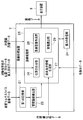
- FIG. 1 is a diagram showing a configuration of an endoscope system 1.
- an endoscope system 1 includes an endoscope device 4 having an endoscope 2 and a camera control unit (CCU) 3, a position detection device 5, a server 6, and an image processing device 7. And a display device 8.
- CCU camera control unit
- the endoscope 2 includes an elongated insertion portion 11 having flexibility, which is inserted into a subject, an operation portion 12 connected to a proximal end portion of the insertion portion 11, and a side surface of the operation portion 12. And an extended cable 13.
- the operation unit 12 includes a release button 12a that is an imaging instruction unit that generates imaging instruction data for acquiring a captured image for recording (an imaging instruction is input), and an image of an image that is observing the subject.
- An angle-of-view display button 12b for generating angle-of-view display instruction data for displaying an angle (inputting an angle-of-view display instruction) and a freeze angle of view for displaying the angle of view at the time of operation during the effective period.
- Freeze angle of view display button 12c as an acquisition instruction section for generating display instruction data (input of freeze angle of view display instruction) and accumulated angle of view display instruction data for accumulating and displaying past angle of view display information.
- a cumulative view angle display button 12d which is a cumulative display instruction portion to be generated (a cumulative view angle display instruction is input).
- the view angle display button 12b is a superimposed image selection instruction unit to which a selection instruction for selecting ON / OFF of the superimposed image generation is input.
- buttons 12a to 12d as described above are not limited to being provided on the operation unit 12 of the endoscope 2.
- the buttons 12a to 12d may be provided as foot switches, or may be provided as switches having other configurations. Absent.
- An imaging system 10 for imaging the inside of the subject is provided at the distal end of the insertion unit 11.
- the imaging system 10 includes an objective optical system that forms an optical image in the subject, and a CCD that photoelectrically converts the optical image formed by the objective optical system to generate an imaging signal.
- the endoscope 2 is connected to the CCU 3 via the cable 13, and an imaging signal captured by the imaging system 10 is transmitted to the CCU 3.
- the CCU 3 performs predetermined image processing on the imaging signal transmitted from the endoscope 2 to generate endoscope image data. Further, the CCU 3 generates endoscope specification data including angle-of-view information based on the model number of the connected endoscope 2 and the like, the operation state of the endoscope apparatus 4 and the like.
- endoscope specification data including angle-of-view information based on the model number of the connected endoscope 2 and the like, the operation state of the endoscope apparatus 4 and the like.
- the electronic zoom is performed by the image processing of the CCU 3
- the field angle range of the observation image changes, and also when the endoscope 2 includes a zoomable objective optical system. Therefore, real-time data at the time of transmission is used as the angle of view information.
- a plurality of receiving coils are provided at a predetermined interval from the distal end portion to the proximal end portion of the insertion portion 11.
- the plurality of receiving coils output electrical signals in accordance with the magnetic field generated by the position detection device 5.
- the endoscope 2 is connected to the position detection device 5 via the cable 14, and each electric signal output from the reception coil is transmitted to the position detection device 5.
- the position detection device 5 as a position information acquisition unit is based on an electrical signal from a reception coil provided at the distal end of the insertion unit 11 among a plurality of reception coils, more specifically, the distal end of the insertion unit 11.
- this position information includes each information of the three-dimensional position of the objective optical system and the optical axis direction of the objective optical system.
- the acquisition of the position information by the position detection device 5 is repeatedly performed at regular time intervals, for example.
- the position detection device 5 calculates and acquires insertion shape data indicating the insertion shape of the insertion portion 11 based on the electrical signals from the plurality of reception coils described above.
- the curved shape data is acquired using the receiving coil.
- the present invention is not limited to this.
- the curved shape data is acquired using an FBG (Fiber Bragg Grating) sensor or the like. It doesn't matter.
- the CCU 3, the position detection device 5, and the server 6 described above are connected to the image processing device 7.
- the server 6 is connected to the image processing apparatus 7 via a communication line such as a hospital LAN.
- the CCU 3 includes endoscope image data, endoscope specification data, each instruction data such as the above-described imaging instruction data, field angle display instruction data, freeze field angle display instruction data, cumulative field angle display instruction data, Is transmitted to the image processing apparatus 7.
- the position detection device 5 transmits the position information (position and direction data) of the objective optical system and the insertion shape data of the insertion unit 11 to the image processing device 7.
- the server 6 stores preoperative multi-slice image data 16a to 16n acquired in advance by CT, MRI, PET, or the like, for example, before performing the examination by the endoscope system 1. Then, the server 6 transmits these preoperative multi-slice image data 16a to 16n to the image processing device 7.
- the image processing apparatus 7 reads the preoperative multi-slice image data 16a to 16n from the server 6, but instead of this, a CD-ROM or the like in which the preoperative multi-slice image data 16a to 16n is stored can be used. Of course, it is possible to read from a portable recording medium.
- the image processing apparatus 7 creates image data by performing a process described later based on each data fetched from the CCU 3, the position detection apparatus 5, and the server 6.
- the image processing device 7 is connected to the display device 8, and the display device 8 receives and displays the image data created by the image processing device 7.
- the display device 8 is a display unit that displays a superimposed image created by the image processing device 7.
- FIG. 2 is a block diagram showing a configuration of the image processing apparatus 7.
- the image processing device 7 includes a first storage unit 21, a luminal organ extraction unit 22, an image processing unit 23, and a second storage unit 24.
- the first storage unit 21 stores preoperative multi-slice image data 16a to 16n, which are image information about a subject acquired in advance for constructing three-dimensional image information.
- the luminal organ extracting unit 22 reads out the image information stored in the first storage unit 21 to construct three-dimensional image information, and further stores predetermined luminal organ image information existing in the three-dimensional image information. Extract.
- the extracted luminal organ image information is image information indicating the luminal structure of the kidney.
- the luminal organ extraction unit 22 uses, for example, the ureter 42, the renal pelvis 43, the large renal cup 44, the small renal cup 45, and the renal papilla 46 (or the bladder and urethra as necessary) as the luminal organ 41.
- a predetermined luminal organ is extracted (see FIG. 4).
- the image processing unit 23 includes an alignment unit 26, an angle-of-view display information generation unit 27, a superimposed image creation unit 28, and an image reading unit 29.
- the alignment unit 26 obtains position information (position information of the objective optical system) acquired by the position detection device 5 with respect to predetermined lumen organ image information as three-dimensional image information extracted by the lumen organ extraction unit 22. ).
- the alignment by the alignment unit 26 is performed, for example, by calculating a conversion formula from real space coordinates acquired by the position detection device 5 to 3D image coordinates for constructing 3D image information.
- the alignment method is not limited to the method using the above-described conversion formula.
- the position detection of the feature points on the patient's body surface as disclosed in Japanese Patent Application Laid-Open No. 2005-31770 is possible.
- a registration method based on feature point designation on 3D image data, or by matching an endoscopic image and a virtual endoscopic image as disclosed in Japanese Patent Application Laid-Open No. 2009-279251 An alignment method or the like may be employed.
- the angle-of-view display information generation unit 27 is based on the angle-of-view information in the endoscope specification data received from the CCU 3, and the angle-of-view display information indicating the angle-of-view information of the captured image captured by the imaging system 10 including the objective optical system. Is generated. Specifically, the angle-of-view display information generated by the angle-of-view display information generation unit 27 includes a boundary line indicating a range of angle of view that extends from one point. Specific examples include a sector shape and a cone shape. And quadrangular pyramids.
- the sector shape is suitable for superimposing on two-dimensional image information created from, for example, three-dimensional image information
- the cone shape is suitable for superimposing on three-dimensional image information
- the quadrangular pyramid shape is an image sensor. It is suitable for superimposing on the three-dimensional image information in consideration of the shape of the imaging surface (generally, a quadrangular shape).
- the image processing unit 23 sets the starting point of the boundary line in the view angle display information to the position of the objective optical system indicated by the position information aligned by the alignment unit 26.
- the superimposed image creation unit 28 of the image processing unit 23 has an angle of view generated by the angle-of-view display information generation unit 27 at a position indicated by the position information aligned by the alignment unit 26 in predetermined luminal organ image information.
- a superimposed image is created by superimposing display information.
- the superimposed image creating unit 28 creates the superimposed image at regular time intervals until the superimposed image generation off is selected. This is performed in accordance with the acquisition of position information by the position detection device 5 that is repeatedly performed. At this time, the display device 8 displays the superimposed image while the selection instruction is on the superimposed image generation. Thereby, the view angle display information is displayed in real time. Further, when the superimposed image generation off is selected by the view angle display button 12b, the superimposed image creation unit 28 does not generate a superimposed image, for example (however, as described later, the superimposed image is stored in the second storage unit 24). When the following cumulative view angle display is performed, a superimposed image may be created regardless of the operation state of the view angle display button 12b).
- the superimposed image creating unit 28 repeats the superimposed image according to the acquisition of the position information by the position detection device 5 repeatedly performed at regular time intervals. Will be made.
- the superimposed image creation unit 28 may create a superimposed image when the operation is performed.
- the superimposing process by the superimposing image creating unit 28 includes a case where the angle-of-view display information is superimposed on predetermined luminal organ image information as three-dimensional image information extracted by the luminal organ extracting unit 22, and There is a case where the predetermined luminal organ image information as the two-dimensional image information is created as an overhead image or a cut-out image from the predetermined luminal organ image information as the image information and then the angle of view display information is superimposed. .
- the two-dimensional superimposed image becomes image data to be output to the display device 8, but when the created superimposed image is a three-dimensional image, image processing is performed.
- the unit 23 creates a two-dimensional superimposed image such as an overhead image or a cut-out image from the superimposed image and sets it as image data to be output to the display device 8.
- the second storage unit 24 stores the generated two-dimensional superimposed image, position information and angle-of-view information (specifically, based on preoperative multi-slice image data 16a to 16n stored in the server 6). At least one of position information (position and direction data) and field-of-view information of the captured image), which is data for creating a superimposed image, is stored.
- the second storage unit 24 includes at least a two-dimensional superimposed image, position information, and angle-of-view information in order to make it easier to later understand the position and direction in which the recorded photograph to be placed on the medical chart or the like was taken.
- One storage may be performed in association with the captured image captured by the imaging system 10. At this time, it is preferable to include the timing at which an imaging instruction is input from the release button 12a, which is an imaging instruction unit, in the timing at which the associated storage is performed.
- the image reading unit 29 displays the two-dimensional superimposed image read from the second storage unit 24 or the two-dimensional superimposed image created based on the position information and the angle-of-view information read from the second storage unit 24. 8 for display.
- the freeze angle-of-view display instruction data generated by the freeze angle-of-view display button 12c, which is the acquisition instruction unit described above, is an acquisition instruction for acquiring information from the second storage unit 24.
- the image reading unit 29 reads the two-dimensional superimposed image at the input start time of the acquisition instruction from the second storage unit 24 in response to the acquisition instruction.
- the image reading unit 29 reads position information and angle-of-view information at the input start point of the acquisition instruction from the second storage unit 24 according to the acquisition instruction, and based on the read position information and angle-of-view information, The processing unit 23 is caused to create a two-dimensional superimposed image.
- the image reading unit 29 continues to output the two-dimensional superimposed image for display while the acquisition instruction is valid. As a result, during the period when the acquisition instruction is valid, the angle of view at the time when the freeze angle-of-view display button 12c is operated is continuously displayed.
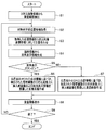
- FIG. 3 is a flowchart showing the operation of the endoscope system 1
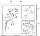
- FIG. 4 is a diagram showing a display example of the display screen 8 a of the display device 8.
- the image displayed on the display screen 8a in FIG. 4 is final two-dimensional image data after being processed by the image processing apparatus 7, but in the following, the two-dimensional image data shown in FIG. The description will be made using symbols as appropriate.
- an overhead image 31, a virtual endoscopic image 32, and an endoscopic image 33 are displayed on the display screen 8 a of the display device 8.
- the bird's-eye view image 31 is a two-dimensional image of the luminal organ observed stereoscopically when the luminal organ constructed as three-dimensional image data is looked down on.
- the virtual endoscopic image 32 is a two-dimensional image when a luminal organ constructed as three-dimensional image data is observed from the viewpoint of the objective optical system.
- the endoscopic image 33 is a captured image captured by the imaging system 10. Note that the display example shown in FIG. 4 is merely an example, and other information may be displayed or some information may be omitted.
- the ureter 42, the renal pelvis 43, the large renal cup 44, the small renal cup 45, and the renal papilla 46 in the luminal organ 41 are displayed.
- An insertion portion image 51 showing the insertion shape is displayed.
- the tip of the insertion portion image 51 is the current position 50 of the objective optical system.
- the current position 50 of the objective optical system is within the great kidney cup 44.
- the endoscopic image 33 shown in FIG. 4 displays the openings of a plurality of small renal cups 45 observed from the large renal cup 44 corresponding to the objective optical system of the insertion unit 11 being in the large renal cup 44. Has been.
- the virtual endoscopic image 32 displays openings of a plurality of small kidney cups 45 that should be observed from the current position 50 of the objective optical system.
- the surgeon first inserts the target small renal cup 45 using the same navigation as in the prior art. Then, an inspection is performed to look around the target small renal cup 45 with an endoscope. In such an examination, the angle of view is displayed when the surgeon operates the angle of view display button 12b of the operation unit 12 at a desired timing.
- the navigation similar to the conventional one is used again. Then, it moves to the next small renal cup 45 for observation.
- the surgeon can operate the view angle display button 12b to turn off the view angle display.
- the luminal organ extracting unit 22 reads out preoperative multi-slice image data 16a to 16n to construct three-dimensional image information as described above, and further, in the constructed three-dimensional image information.
- the predetermined luminal organ image information existing in is extracted (step S1).
- the alignment unit 26 acquires position information (position and direction data) of the objective optical system from the position detection device 5 (step S2).
- the alignment unit 26 performs alignment between the real space coordinates indicated by the acquired position information and the 3D image coordinates where the 3D image information is constructed (step S3).
- the angle-of-view display information generation unit 27 acquires the endoscope specification data from the CCU 3, and based on the angle-of-view information included in the endoscope specification data, the angle-of-view display including a boundary line indicating the angle-of-view range. Information is generated (step S4).
- the image processing unit 23 determines whether or not the view angle display button 12b is operated and the view angle display instruction data is input from the CCU 3 (step S5).
- the superimposed image creation unit 28 is extracted by the luminal organ extraction unit 22 based on the position information aligned by the alignment unit 26.
- a superimposed image is created by superimposing the angle-of-view display information generated by the insertion portion image 51 and the angle-of-view display information generating unit 27 on the three-dimensional image of the luminal organ (step S6).
- the superimposed image creation unit 28 is extracted by the luminal organ extraction unit 22 based on the position information aligned by the alignment unit 26.
- a superimposed image is created by superimposing the insertion portion image 51 on the three-dimensional image of the hollow organ (step S7).
- the image processing unit 23 creates an overhead image 31 from the created superimposed image, configures image data for display together with the virtual endoscopic image 32 and the endoscopic image 33, and then transmits the image data to the display device 8. Output. Accordingly, an image including the overhead image 31 as a superimposed image is displayed on the display device 8 (step S8).
- step S9 it is determined whether or not to end this process.
- the process returns to step S2 to repeat the above-described process, and when it is determined to end. This process is finished.
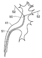
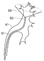
- FIG. 5 is a diagram illustrating an example of the overhead image 31 on which the view angle display information 52 is superimposed.
- the angle-of-view display information 52 generated as a boundary line that forms a fan-shaped angle indicating the angle-of-view range starting from the position 50 of the objective optical system at the tip of the insertion portion image 51 of the overhead image 31 is the optical axis of the objective optical system. It is displayed so as to spread around the direction that matches the direction.
- the opening of the small kidney cup 45 that is observed, the opening of the small kidney cup 45 that is not observed, Can be determined. That is, the opening of the small kidney cup 45 displayed in the endoscopic image 33 and the virtual endoscopic image 32 is three in the example shown in FIG. 4, whereas the overhead image 31 shown in FIG. In FIG. 4, when there are four, it is determined that the opening of one small renal cup 45 is not observed.
- This determination may be performed by the surgeon by comparing the bird's-eye view image 31 as shown in FIG. 5 with the endoscopic image 33 or the virtual endoscopic image 32, but the image processing unit 23 performs the determination process.
- the determination result may be displayed as one piece of navigation information.
- FIG. 6 is a diagram showing an example in which an observable / impossible mark is attached to the overhead image 31 together with the view angle display information 52.
- an observable mark 53 and an unobservable mark 54 are formed in the opening of the small renal cup 45 within the range indicated by the view angle display information 52 of the luminal organ 41 in the overhead image 31. May be displayed.
- the display shown in FIG. 6 is an example, and other display modes may be used, and navigation may be performed by voice or other methods together with or instead of the display.
- FIG. 7 is a diagram showing another example of the overhead image 31 on which the view angle display information 52 is superimposed.
- the field angle display information 52 shown in FIG. 5 is only a fan-shaped boundary line, since the actual observation range is a solid angle, the field angle display information 55 is displayed as a cone in the example shown in FIG. Information.
- the display information may be, for example, a quadrangular pyramid in consideration of the shape of the imaging surface of the imaging device.
- FIG. 8 is a diagram showing an example in which the angle-of-view display information is displayed on a plurality of overhead images 31 and 34 viewed from different directions.
- the image processing unit 23 can create a plurality of two-dimensional superimposed images viewed from different directions.
- the endoscopic image 33, the overhead image 31 and the second overhead image 34 viewed from a different angle from the overhead image 31 are displayed on the display screen 8a of the display device 8.
- the second overhead image 34 is displayed instead of the virtual endoscope image 32, but the overhead image 31, the virtual endoscope image 32, and the endoscope image 33 are further displayed.
- the second overhead image 34 may be displayed.
- the second bird's-eye view image 34 is an image when seen from the direction of arrow A in FIG. 8, and the image processing unit 23 uses the three-dimensional image coordinates for the luminal organ constructed as the three-dimensional image information. It is generated by rotating within.
- angle-of-view display information 52 including fan-shaped boundary lines having a predetermined length is displayed in the bird's-eye view image 31 as in FIG.
- angle-of-view display information 52a indicating a circular angle-of-view range is displayed.
- the angle-of-view display information 52a may be, for example, a rectangle in consideration of the shape of the imaging surface of the imaging element, as described above.
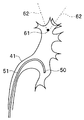
- FIG. 9 is a diagram showing an example of the view angle display information displayed when the freeze view angle display button 12c is operated.
- the view angle display information is displayed in real time starting from the current position 50 of the objective optical system.
- freeze angle-of-view display button 12c which is the acquisition instruction unit
- the angle-of-view display information at the time of the operation is continuously displayed while the freeze angle-of-view display instruction is valid. It is like that.
- the freeze angle-of-view display button 12c is an acquisition instruction unit to which an acquisition instruction for acquiring information from the second storage unit 24 is input.
- the image processing device 7 reads the preoperative multi-slice image data 16a to 16n from the server 6 and reads the position from the second storage unit 24. After the information and the angle-of-view information are aligned by the alignment unit 26, a two-dimensional superimposed image at the start time of input of the acquisition instruction is created.
- the image reading unit 29 displays the two-dimensional superimposed image at the input start time of the acquisition instruction, which is read or created based on the read information, for display while the acquisition instruction is valid. To continue to output.
- the view angle display information 62 is obtained by operating the freeze view angle display button 12c.
- the freeze display is continued starting from the position 61 of the objective optical system at the time.
- This freeze display is erased from the screen when the freeze view angle display button 12c is subsequently operated to cancel the freeze view angle display instruction.
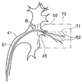
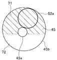
- FIG. 10 is a diagram illustrating an example of the view angle display information displayed on the overhead view image when the cumulative view angle display button 12d is operated, and FIG. 11 is different when the cumulative view angle display button 12d is operated. It is a figure which shows the example of the view angle display information displayed on the bird's-eye view image seen from the direction.
- FIG. 11 shows an image when viewed from the direction of arrow B in FIG.
- the second storage unit 24 stores at least one of a two-dimensional superimposed image, position information, and field angle information at a plurality of past times.
- the cumulative field angle display since it is also possible to reset the cumulative field angle display, when a reset operation is performed, it is acquired at the time before the reset operation and the two-dimensional superimposed image acquired at the time before the reset operation.
- the position information and the angle-of-view information may be deleted.
- the image processing unit 23 cumulatively superimposes the two-dimensional superimposed images at a plurality of past time points, and at the past plural time points. At least one of position information and angle-of-view information is read from the second storage unit 24.
- the image processing apparatus 7 sends pre-operative multi-slice image data 16a to 16 from the server 6. 16n is read, and the position information and angle-of-view information at the past plural time points read from the second storage unit 24 are aligned by the aligning unit 26, and then a two-dimensional superimposed image at the past plural time points is created. .
- the image processing unit 23 reads out from the second storage unit 24, or created based on the position information and the angle of view information read out from the second storage unit 24, and two-dimensional superimposition at a plurality of past times.
- An image is cumulatively superimposed to create a cumulative two-dimensional superimposed image in which past angles of view are accumulated and displayed.
- FIGS. 10 and 11 a cumulative two-dimensional superimposed image as shown in FIGS. 10 and 11 is displayed on the display device 8.
- FIG. 10 and FIG. 11 show a state when the inside of the small renal cup 45 is observed from the opening 45a of the small renal cup 45.
- FIG. 10 and FIG. 11 show a state when the inside of the small renal cup 45 is observed from the opening 45a of the small renal cup 45.
- FIG. 10 and FIG. 11 show a state when the inside of the small renal cup 45 is observed from the opening 45a of the small renal cup 45.
- the inside 45b of the small renal cup 45 is wider than the opening 45a.
- the accumulated field angle display information 71 indicated by hatching indicates an observed field angle range in the inside 45 b of the small kidney cup 45.
- view angle display information 52 and 52a indicate the range of the inside 45b of the small renal cup 45 observed from the current position 50 of the objective optical system.
- a region 72 indicates an unobserved region in the small kidney cup 45.
- the area including the specific small area that is, the enlargement target area as shown by a two-dot chain line in FIG. 73 may be enlarged and displayed.
- the enlargement target area 73 may be automatically enlarged and displayed.
- the observation range in the luminal organ is reduced. It becomes possible to present it in an easy-to-understand manner.
- the second storage unit 24 that stores at least one of the two-dimensional superimposed image, the position information, and the angle of view information is provided, the observation range at a certain time can be confirmed at a later time. Become. In particular, when storing position information and angle-of-view information, it is possible to reduce the storage capacity compared to storing a two-dimensional superimposed image.
- the second storage unit 24 since at least one of the two-dimensional superimposed image, the position information, and the angle-of-view information stored by the second storage unit 24 is stored in association with the captured image captured by the imaging system 10, a medical record or the like When a captured image is captured as a recorded photograph to be placed on the camera, the recorded photograph is captured by referring to the associated two-dimensional superimposed image or the two-dimensional superimposed image created from the associated positional information and angle-of-view information. The range can be easily grasped.
- the imaging instruction unit 24 storage associated with at least one of the two-dimensional superimposed image, the position information, and the angle-of-view information by the second storage unit 24 is performed when an imaging instruction is input from the imaging instruction unit. If this is done (that is, if the timing at which the associated instruction is stored includes the timing at which the imaging instruction is input from the release button 12a, which is the imaging instruction unit), the imaging range at the time when the captured image is acquired is surely determined. It becomes possible to grasp.
- the image reading unit 29 reads out the two-dimensional superimposed image at the input start time of the acquisition instruction read from the second storage unit 24 according to the acquisition instruction or the second storage unit 24 according to the acquisition instruction. Since the two-dimensional superimposed image created based on the position information and the angle-of-view information when the acquisition instruction is input is continuously output for display while the acquisition instruction is valid, the freeze angle-of-view display instruction is issued. It is possible to continuously view the observation range at the time point when the freeze display is effective. As a result, even if the current position 50 of the objective optical system changes finely, for example, the observation range at the time of the indication of the freeze angle of view can be stably viewed.
- the image processing unit 23 creates a superimposed image in response to the position information being acquired by the position detection device 5
- the field angle display information can be displayed in real time. It is also possible to store in advance a superimposed image for displaying the cumulative angle of view.
- the image processing unit 23 Since the image processing unit 23 generates a superimposed image when the superimposed image generation ON is selected by the view angle display button 12b and does not generate a superimposed image when the superimposed image generation OFF is selected, real-time display is performed. Therefore, a superimposed image is generated only when necessary, and the processing load can be reduced when real-time display is unnecessary.
- the display device 8 displays the superimposed image while the selection instruction is on the superimposed image generation ON, it is possible to observe the view angle display information displayed in real time. Further, even for an operator who does not like to always display the angle-of-view display information in a superimposed manner, the display of the angle-of-view display information can be turned on / off by selecting on / off of the superimposed image generation. It is possible to switch.
- the observation range can be grasped in a three-dimensional manner.
- the view angle display information includes a boundary line indicating a view angle range extending from the position of the objective optical system indicated by the position information, the range observed from the position of the objective optical system can be easily set. It becomes possible to grasp.
- the image processing unit 23 Since the image processing unit 23 creates a cumulative two-dimensional superimposed image in which two-dimensional superimposed images at a plurality of past times are cumulatively superimposed when a cumulative field angle display instruction is input, Thus, it is possible to easily check the completed area and the unobserved area.
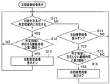
- FIG. 12 shows a second embodiment of the present invention, and is a flowchart showing an automatic superimposed image display process in the endoscope system 1.
- the same parts as those in the first embodiment are denoted by the same reference numerals and the description thereof is omitted as appropriate, and only different points will be mainly described.
- the display of the superimposed image that is, the display of the view angle display information is performed according to the button operation from the operator, but this embodiment is performed by automatic processing. ing.
- step S11 when the processing shown in FIG. 12 is started, it is determined whether or not the objective optical system is present in a predetermined region, specifically in the small kidney cup 45 (step S11).
- step S12 when it is determined that it exists in the predetermined area, it is determined whether or not the duration time existing in the predetermined area is equal to or longer than the first threshold (step S12).
- step S13 if it is determined that the threshold value is equal to or greater than the first threshold value, the automatic superimposed image display is turned on (step S13). If it is determined that the threshold value is less than the first threshold value, the process proceeds to step S13. The process returns to the determination in step S11 without performing the process.
- the automatic superimposed image display is turned on in step S13, the process of creating and displaying the superimposed image as described in the first embodiment in real time is performed.
- step S11 If it is determined in step S11 that the objective optical system does not exist within the predetermined area, it is determined whether or not the automatic superimposed image display is currently on (step S14).
- step S15 if it is determined that the automatic superimposed image display is on, it is determined whether or not the duration that does not exist in the predetermined area is equal to or greater than the second threshold (step S15).
- step S16 If it is determined that the threshold value is greater than or equal to the second threshold, the automatic superimposed image display is turned off (step S16), and the automatic superimposed image display is determined to be off in step S14. If it is determined in step S15 that it is less than the second threshold, the process returns to step S11.
- the same effect as that of the first embodiment described above can be obtained, and the superimposed image can be displayed when the duration time during which the objective optical system is present in the predetermined region is equal to or greater than the first threshold value. Since it is automatically created, when observing a specific region such as the small renal cup 45, it is possible to grasp the range to be observed without requiring manual operation.
- the angle of view is near the entrance of a specific area such as the small kidney cup 45. It is possible to prevent the display on / off of the display information from being unstablely switched, and to perform observation while viewing a stable display screen.
- the display of the superimposed image is turned off. It is possible to move the insertion position while observing a screen on which no information is displayed.
- the endoscope system may be an operation method of the endoscope system that operates the endoscope system as described above, or a program for causing a computer to execute the operation method. It may be a non-temporary recording medium that can be read by a computer that records the program.
- the present invention is not limited to the above-described embodiment as it is, and can be embodied by modifying the constituent elements without departing from the scope of the invention in the implementation stage.
- various aspects of the invention can be formed by appropriately combining a plurality of components disclosed in the embodiment. For example, you may delete some components from all the components shown by embodiment.
- the constituent elements over different embodiments may be appropriately combined.
Landscapes
- Health & Medical Sciences (AREA)
- Life Sciences & Earth Sciences (AREA)
- Surgery (AREA)
- Physics & Mathematics (AREA)
- Engineering & Computer Science (AREA)
- Optics & Photonics (AREA)
- Veterinary Medicine (AREA)
- Animal Behavior & Ethology (AREA)
- Pathology (AREA)
- Public Health (AREA)
- Biophysics (AREA)
- Biomedical Technology (AREA)
- Heart & Thoracic Surgery (AREA)
- Medical Informatics (AREA)
- Molecular Biology (AREA)
- General Health & Medical Sciences (AREA)
- Nuclear Medicine, Radiotherapy & Molecular Imaging (AREA)
- Radiology & Medical Imaging (AREA)
- Signal Processing (AREA)
- Astronomy & Astrophysics (AREA)
- General Physics & Mathematics (AREA)
- Human Computer Interaction (AREA)
- Endoscopes (AREA)
- Instruments For Viewing The Inside Of Hollow Bodies (AREA)
Abstract
Description
図1から図11は本発明の実施形態1を示したものであり、図1は内視鏡システム1の構成を示す図である。
図12は本発明の実施形態2を示したものであり、内視鏡システム1における自動重畳画像表示処理を示すフローチャートである。この実施形態2において、上述の実施形態1と同様である部分については同一の符号を付すなどして説明を適宜省略し、主として異なる点についてのみ説明する。
Claims (13)
- 3次元画像情報を構築するための、予め取得した被検体に関する画像情報を記憶する第1の記憶部と、
前記画像情報から前記3次元画像情報を構築して当該3次元画像情報内に存在する所定の管腔臓器画像情報を抽出する管腔臓器抽出部と、
前記被検体内の光学像を結像する対物光学系の位置情報を取得する位置情報取得部と、
前記所定の管腔臓器画像情報に対して、前記位置情報取得部で取得された位置情報を位置合わせする位置合わせ部と、
前記対物光学系を含む撮像系によって撮像された撮像画像の画角情報を示す画角表示情報を生成する画角表示情報生成部と、
前記所定の管腔臓器画像情報における前記位置合わせ部によって位置合わせされた前記位置情報で示される位置に、前記画角表示情報を重畳した重畳画像を作成する画像処理部と、
を具備することを特徴とする内視鏡システム。 - 前記画像処理部は、さらに、前記重畳画像から2次元重畳画像を作成可能であり、
前記2次元重畳画像と、前記位置情報および前記画角情報と、の少なくとも一方を記憶する第2の記憶部をさらに具備することを特徴とする請求項1に記載の内視鏡システム。 - 前記第2の記憶部は、前記2次元重畳画像と、前記位置情報および前記画角情報と、の少なくとも一方を、前記撮像画像に関連付けて記憶することを特徴とする請求項2に記載の内視鏡システム。
- 前記撮像画像を取得するための撮像指示が入力される撮像指示部をさらに具備し、
前記第2の記憶部は、前記撮像指示部から前記撮像指示が入力された場合に、前記2次元重畳画像と、前記位置情報および前記画角情報と、の少なくとも一方を、前記撮像画像に関連付けて記憶することを特徴とする請求項3に記載の内視鏡システム。 - 前記第2の記憶部から情報を取得するための取得指示が入力される取得指示部と、
前記取得指示に応じて前記第2の記憶部から読み出した該取得指示の入力開始時点における前記2次元重畳画像、または、前記取得指示に応じて前記第2の記憶部から読み出した該取得指示の入力開始時点における前記位置情報および前記画角情報に基づき作成された2次元重畳画像を、該取得指示が有効である間は表示用に出力し続ける画像読出部と、
をさらに具備することを特徴とする請求項2に記載の内視鏡システム。 - 前記画像処理部は、前記位置情報取得部により前記位置情報が取得されることに応じて前記重畳画像を作成することを特徴とする請求項1に記載の内視鏡システム。
- 重畳画像生成オン/オフを選択するための選択指示が入力される重畳画像選択指示部をさらに具備し、
前記画像処理部は、前記選択指示が重畳画像生成オンであるときには前記重畳画像を生成し、前記選択指示が重畳画像生成オフであるときには前記重畳画像を生成しないことを特徴とする請求項1に記載の内視鏡システム。 - 前記重畳画像を表示する表示部をさらに具備し、
前記表示部は、前記選択指示が重畳画像生成オンである間は前記重畳画像を表示することを特徴とする請求項7に記載の内視鏡システム。 - 前記画像処理部は、さらに、前記重畳画像から、異なる複数方向から見た複数の2次元重畳画像を作成することを特徴とする請求項1に記載の内視鏡システム。
- 前記画角表示情報は、前記位置情報で示される前記対物光学系の位置を起点として延伸する画角範囲を示す境界線を含むことを特徴とする請求項1に記載の内視鏡システム。
- 過去の画角表示情報を累積して表示するための累積画角表示指示が入力される累積表示指示部をさらに具備し、
前記第2の記憶部は、過去の複数の時点における、前記2次元重畳画像と、前記位置情報および前記画角情報と、の少なくとも一方を記憶し、
前記画像処理部は、さらに、前記累積画角表示指示が入力された場合には、過去の複数の時点における前記2次元重畳画像を累積的に重畳した累積2次元重畳画像と、過去の複数の時点における前記位置情報および前記画角情報に基づき作成された累積2次元重畳画像と、の少なくとも一方を作成することを特徴とする請求項2に記載の内視鏡システム。 - 前記画像処理部は、前記位置情報に基づき前記対物光学系が所定領域内に存在すると判定される継続時間が第1の閾値以上となった場合には、その後に該所定領域内に存在しないと判定される継続時間が第2の閾値以上になるまでは、重畳画像を自動的に作成することを特徴とする請求項1に記載の内視鏡システム。
- 第1の記憶部と、管腔臓器抽出部と、位置情報取得部と、位置合わせ部と、画角表示情報生成部と、画像処理部と、を具備する内視鏡システムの作動方法であって、
前記第1の記憶部が、3次元画像情報を構築するための、予め取得した被検体に関する画像情報を記憶し、
前記管腔臓器抽出部が、前記画像情報から前記3次元画像情報を構築して当該3次元画像情報内に存在する所定の管腔臓器画像情報を抽出し、
前記位置情報取得部が、前記被検体内の光学像を結像する対物光学系の位置情報を取得し、
前記位置合わせ部が、前記所定の管腔臓器画像情報に対して、前記位置情報取得部で取得された位置情報を位置合わせし、
前記画角表示情報生成部が、前記対物光学系を含む撮像系によって撮像された撮像画像の画角情報を示す画角表示情報を生成し、
前記画像処理部が、前記所定の管腔臓器画像情報における前記位置合わせ部によって位置合わせされた前記位置情報で示される位置に、前記画角表示情報を重畳した重畳画像を作成することを特徴とする内視鏡システムの作動方法。
Priority Applications (4)
| Application Number | Priority Date | Filing Date | Title |
|---|---|---|---|
| JP2015562616A JP5945643B2 (ja) | 2014-06-10 | 2015-04-28 | 内視鏡システム、内視鏡システムの作動方法 |
| EP15806951.8A EP3095377A4 (en) | 2014-06-10 | 2015-04-28 | Endoscope system and endoscope system operation method |
| CN201580009481.5A CN106028903B (zh) | 2014-06-10 | 2015-04-28 | 内窥镜系统、内窥镜系统的工作方法 |
| US15/244,270 US9918614B2 (en) | 2014-06-10 | 2016-08-23 | Endoscope system with angle-of-view display information overlapped on three-dimensional image information |
Applications Claiming Priority (2)
| Application Number | Priority Date | Filing Date | Title |
|---|---|---|---|
| JP2014119754 | 2014-06-10 | ||
| JP2014-119754 | 2014-06-10 |
Related Child Applications (1)
| Application Number | Title | Priority Date | Filing Date |
|---|---|---|---|
| US15/244,270 Continuation US9918614B2 (en) | 2014-06-10 | 2016-08-23 | Endoscope system with angle-of-view display information overlapped on three-dimensional image information |
Publications (1)
| Publication Number | Publication Date |
|---|---|
| WO2015190186A1 true WO2015190186A1 (ja) | 2015-12-17 |
Family
ID=54833291
Family Applications (1)
| Application Number | Title | Priority Date | Filing Date |
|---|---|---|---|
| PCT/JP2015/062830 WO2015190186A1 (ja) | 2014-06-10 | 2015-04-28 | 内視鏡システム、内視鏡システムの作動方法 |
Country Status (5)
| Country | Link |
|---|---|
| US (1) | US9918614B2 (ja) |
| EP (1) | EP3095377A4 (ja) |
| JP (1) | JP5945643B2 (ja) |
| CN (1) | CN106028903B (ja) |
| WO (1) | WO2015190186A1 (ja) |
Cited By (1)
| Publication number | Priority date | Publication date | Assignee | Title |
|---|---|---|---|---|
| WO2023148812A1 (ja) * | 2022-02-01 | 2023-08-10 | 日本電気株式会社 | 画像処理装置、画像処理方法及び記憶媒体 |
Families Citing this family (6)
| Publication number | Priority date | Publication date | Assignee | Title |
|---|---|---|---|---|
| JP6828465B2 (ja) * | 2017-01-30 | 2021-02-10 | セイコーエプソン株式会社 | 内視鏡操作支援システム |
| CN110944567B (zh) * | 2017-08-03 | 2022-10-11 | 索尼奥林巴斯医疗解决方案公司 | 医疗观察装置 |
| WO2019079126A1 (en) * | 2017-10-17 | 2019-04-25 | Verily Life Sciences Llc | DISPLAYING PREOPERATIVE AND INTRA-OPERATIVE IMAGES |
| US11660057B2 (en) * | 2019-07-10 | 2023-05-30 | Stryker Corporation | Systems and methods for persistent ureter visualization |
| CN114785948B (zh) * | 2022-04-14 | 2023-12-26 | 常州联影智融医疗科技有限公司 | 内窥镜调焦方法、装置、内镜图像处理器及可读存储介质 |
| CN116211260B (zh) * | 2023-05-09 | 2023-07-21 | 西南医科大学附属医院 | 一种基于变焦扫描的肾结石形态三维成像系统及方法 |
Citations (7)
| Publication number | Priority date | Publication date | Assignee | Title |
|---|---|---|---|---|
| JP2003225195A (ja) * | 2002-02-01 | 2003-08-12 | Pentax Corp | 可撓性内視鏡のモニター装置 |
| JP2011212244A (ja) * | 2010-03-31 | 2011-10-27 | Fujifilm Corp | 内視鏡観察を支援するシステムおよび方法、並びに、装置およびプログラム |
| WO2012176854A1 (ja) * | 2011-06-23 | 2012-12-27 | 株式会社 東芝 | 医用画像処理装置及び医用画像診断装置 |
| JP2013085593A (ja) * | 2011-10-14 | 2013-05-13 | Toshiba Corp | 医用画像表示装置 |
| JP2013202313A (ja) * | 2012-03-29 | 2013-10-07 | Panasonic Corp | 手術支援装置および手術支援プログラム |
| WO2015029970A1 (ja) * | 2013-08-28 | 2015-03-05 | オリンパスメディカルシステムズ株式会社 | カプセル型内視鏡システム |
| WO2015049962A1 (ja) * | 2013-10-02 | 2015-04-09 | オリンパスメディカルシステムズ株式会社 | 内視鏡システム |
Family Cites Families (20)
| Publication number | Priority date | Publication date | Assignee | Title |
|---|---|---|---|---|
| JPS6281193A (ja) * | 1985-10-03 | 1987-04-14 | Toshiba Corp | 内視鏡装置 |
| DE10246355A1 (de) * | 2002-10-04 | 2004-04-15 | Rust, Georg-Friedemann, Dr. | Interaktive virtuelle Endoskopie |
| US7381183B2 (en) * | 2003-04-21 | 2008-06-03 | Karl Storz Development Corp. | Method for capturing and displaying endoscopic maps |
| JP4537756B2 (ja) | 2004-04-30 | 2010-09-08 | オリンパス株式会社 | 超音波診断装置 |
| JP2006167123A (ja) * | 2004-12-15 | 2006-06-29 | Olympus Corp | 画像処理装置および内視鏡装置 |
| JP2006198031A (ja) * | 2005-01-18 | 2006-08-03 | Olympus Corp | 手術支援システム |
| US7967742B2 (en) * | 2005-02-14 | 2011-06-28 | Karl Storz Imaging, Inc. | Method for using variable direction of view endoscopy in conjunction with image guided surgical systems |
| US9289267B2 (en) * | 2005-06-14 | 2016-03-22 | Siemens Medical Solutions Usa, Inc. | Method and apparatus for minimally invasive surgery using endoscopes |
| EP2110067B1 (en) * | 2007-02-05 | 2014-04-02 | Olympus Medical Systems Corp. | Display device and in-vivo information acquisition system using the same |
| US8527032B2 (en) * | 2007-05-16 | 2013-09-03 | General Electric Company | Imaging system and method of delivery of an instrument to an imaged subject |
| JP5188879B2 (ja) | 2008-05-23 | 2013-04-24 | オリンパスメディカルシステムズ株式会社 | 医療機器 |
| WO2010130056A1 (en) * | 2009-05-14 | 2010-11-18 | University Health Network | Quantitative endoscopy |
| JP5369078B2 (ja) | 2010-11-26 | 2013-12-18 | 富士フイルム株式会社 | 医用画像処理装置および方法、並びにプログラム |
| BR112014009129A2 (pt) * | 2011-10-20 | 2017-04-18 | Koninklijke Philips Nv | sistema e método para exibição holográfica interativa |
| WO2013132880A1 (ja) * | 2012-03-06 | 2013-09-12 | オリンパスメディカルシステムズ株式会社 | 内視鏡システム |
| US20130250081A1 (en) * | 2012-03-21 | 2013-09-26 | Covidien Lp | System and method for determining camera angles by using virtual planes derived from actual images |
| JP6128796B2 (ja) * | 2012-10-25 | 2017-05-17 | オリンパス株式会社 | 挿入システム、挿入支援装置、挿入支援装置の作動方法及びプログラム |
| CN104780826B (zh) * | 2013-03-12 | 2016-12-28 | 奥林巴斯株式会社 | 内窥镜系统 |
| WO2015031877A2 (en) * | 2013-08-30 | 2015-03-05 | Maracaja-Neto Luiz | Endo-navigation systems and methods for surgical procedures and cpr |
| CN106163371B (zh) * | 2014-03-31 | 2018-09-28 | 奥林巴斯株式会社 | 内窥镜系统 |
-
2015
- 2015-04-28 EP EP15806951.8A patent/EP3095377A4/en not_active Withdrawn
- 2015-04-28 JP JP2015562616A patent/JP5945643B2/ja active Active
- 2015-04-28 WO PCT/JP2015/062830 patent/WO2015190186A1/ja active Application Filing
- 2015-04-28 CN CN201580009481.5A patent/CN106028903B/zh active Active
-
2016
- 2016-08-23 US US15/244,270 patent/US9918614B2/en active Active
Patent Citations (7)
| Publication number | Priority date | Publication date | Assignee | Title |
|---|---|---|---|---|
| JP2003225195A (ja) * | 2002-02-01 | 2003-08-12 | Pentax Corp | 可撓性内視鏡のモニター装置 |
| JP2011212244A (ja) * | 2010-03-31 | 2011-10-27 | Fujifilm Corp | 内視鏡観察を支援するシステムおよび方法、並びに、装置およびプログラム |
| WO2012176854A1 (ja) * | 2011-06-23 | 2012-12-27 | 株式会社 東芝 | 医用画像処理装置及び医用画像診断装置 |
| JP2013085593A (ja) * | 2011-10-14 | 2013-05-13 | Toshiba Corp | 医用画像表示装置 |
| JP2013202313A (ja) * | 2012-03-29 | 2013-10-07 | Panasonic Corp | 手術支援装置および手術支援プログラム |
| WO2015029970A1 (ja) * | 2013-08-28 | 2015-03-05 | オリンパスメディカルシステムズ株式会社 | カプセル型内視鏡システム |
| WO2015049962A1 (ja) * | 2013-10-02 | 2015-04-09 | オリンパスメディカルシステムズ株式会社 | 内視鏡システム |
Non-Patent Citations (1)
| Title |
|---|
| See also references of EP3095377A4 * |
Cited By (1)
| Publication number | Priority date | Publication date | Assignee | Title |
|---|---|---|---|---|
| WO2023148812A1 (ja) * | 2022-02-01 | 2023-08-10 | 日本電気株式会社 | 画像処理装置、画像処理方法及び記憶媒体 |
Also Published As
| Publication number | Publication date |
|---|---|
| EP3095377A1 (en) | 2016-11-23 |
| EP3095377A4 (en) | 2017-09-13 |
| CN106028903B (zh) | 2018-07-24 |
| JPWO2015190186A1 (ja) | 2017-04-20 |
| US9918614B2 (en) | 2018-03-20 |
| CN106028903A (zh) | 2016-10-12 |
| JP5945643B2 (ja) | 2016-07-05 |
| US20160353968A1 (en) | 2016-12-08 |
Similar Documents
| Publication | Publication Date | Title |
|---|---|---|
| JP5945643B2 (ja) | 内視鏡システム、内視鏡システムの作動方法 | |
| JP4153963B2 (ja) | 内視鏡挿入形状検出装置 | |
| JP5378628B1 (ja) | 内視鏡システム | |
| JP4698966B2 (ja) | 手技支援システム | |
| JP5687811B1 (ja) | 内視鏡システム | |
| JP4733243B2 (ja) | 生検支援システム | |
| EP2904958A1 (en) | Endoscopic system | |
| JP5977900B2 (ja) | 画像処理装置 | |
| JP3850217B2 (ja) | 気管支用内視鏡位置検出装置 | |
| JPWO2004010857A1 (ja) | 内視鏡装置、内視鏡装置のナビゲーション方法、内視鏡画像の表示方法、及び内視鏡用画像表示プログラム | |
| US20210338044A1 (en) | Medical systems and related methods | |
| US10918443B2 (en) | Navigation system and operation method of navigation system | |
| US20170188986A1 (en) | Medical observation system | |
| JP4445792B2 (ja) | 挿入支援システム | |
| KR101492801B1 (ko) | Oct 영상과 심장 삼차원 영상의 정합을 통한 심장 수술 내비게이션 시스템 및 방법 | |
| JP2005211529A (ja) | 手技支援システム |
Legal Events
| Date | Code | Title | Description |
|---|---|---|---|
| ENP | Entry into the national phase |
Ref document number: 2015562616 Country of ref document: JP Kind code of ref document: A |
|
| 121 | Ep: the epo has been informed by wipo that ep was designated in this application |
Ref document number: 15806951 Country of ref document: EP Kind code of ref document: A1 |
|
| REEP | Request for entry into the european phase |
Ref document number: 2015806951 Country of ref document: EP |
|
| WWE | Wipo information: entry into national phase |
Ref document number: 2015806951 Country of ref document: EP |
|
| NENP | Non-entry into the national phase |
Ref country code: DE |