WO2015190023A1 - 車両設定装置 - Google Patents
車両設定装置 Download PDFInfo
- Publication number
- WO2015190023A1 WO2015190023A1 PCT/JP2015/001952 JP2015001952W WO2015190023A1 WO 2015190023 A1 WO2015190023 A1 WO 2015190023A1 JP 2015001952 W JP2015001952 W JP 2015001952W WO 2015190023 A1 WO2015190023 A1 WO 2015190023A1
- Authority
- WO
- WIPO (PCT)
- Prior art keywords
- vehicle
- registered
- vehicle setting
- display units
- sight
- Prior art date
- Legal status (The legal status is an assumption and is not a legal conclusion. Google has not performed a legal analysis and makes no representation as to the accuracy of the status listed.)
- Ceased
Links
Images


Classifications
-
- B—PERFORMING OPERATIONS; TRANSPORTING
- B60—VEHICLES IN GENERAL
- B60R—VEHICLES, VEHICLE FITTINGS, OR VEHICLE PARTS, NOT OTHERWISE PROVIDED FOR
- B60R16/00—Electric or fluid circuits specially adapted for vehicles and not otherwise provided for; Arrangement of elements of electric or fluid circuits specially adapted for vehicles and not otherwise provided for
- B60R16/02—Electric or fluid circuits specially adapted for vehicles and not otherwise provided for; Arrangement of elements of electric or fluid circuits specially adapted for vehicles and not otherwise provided for electric constitutive elements
- B60R16/037—Electric or fluid circuits specially adapted for vehicles and not otherwise provided for; Arrangement of elements of electric or fluid circuits specially adapted for vehicles and not otherwise provided for electric constitutive elements for occupant comfort, e.g. for automatic adjustment of appliances according to personal settings, e.g. seats, mirrors, steering wheel
Definitions
- the present disclosure relates to a vehicle setting device that performs various settings for a vehicle.
- Patent Document 1 When a plurality of drivers with similar faces such as parents and children, brothers, etc. drive one vehicle, the configuration described in Patent Document 1 may not be able to accurately identify which driver is seated in the driver's seat. . Even parents, siblings, and the like may have different heights and preferences, and if the driver sitting in the driver's seat cannot be accurately identified, vehicle settings such as mirror position cannot be made properly. Such a problem similarly occurs with respect to other vehicle settings other than the positions of the mirror and the seat.
- the present disclosure has been made for the purpose of providing a vehicle setting device capable of setting a vehicle according to a vehicle occupant.
- the vehicle setting device includes a plurality of display units, a line-of-sight detection unit, a determination unit, and a vehicle setting unit.
- the plurality of display units individually display different characters or designs.
- a gaze detection unit detects a gaze of a vehicle occupant and determines whether or not the gaze has moved in a pre-registered order on a plurality of pre-registered display units among the plurality of display units. Judgment.
- the vehicle setting unit corresponds to the plurality of display units registered in advance and the order. Set the vehicle.
- the vehicle setting device of the present disclosure if an occupant registers in advance in which order the line of sight is transferred to which display unit among a plurality of display units corresponding to the vehicle setting, The corresponding vehicle settings can be made.
- FIG. 1 is a schematic diagram illustrating a configuration of a passenger compartment of a vehicle to which the present disclosure is applied
- FIG. 2 is a block diagram showing the configuration of the vehicle setting device for the vehicle
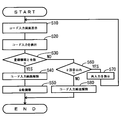
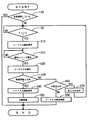
- FIG. 3 is a flowchart of start-up vehicle setting processing in the vehicle setting device
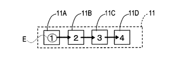
- FIG. 4A is an explanatory view illustrating a display screen by the vehicle setting process at the time of starting
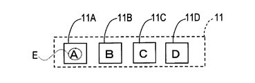
- FIG. 4B is an explanatory diagram illustrating a display screen by the vehicle setting process at the time of start-up
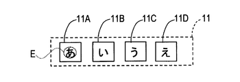
- FIG. 4C is an explanatory view illustrating a display screen by the vehicle setting process at the time of start-up
- FIG. 5 is a flowchart of a post-startup vehicle setting process in the vehicle setting device.
- a windshield 5 is mounted in front of the passenger compartment 3 of the vehicle 1 shown in FIG.
- a steering wheel 9 is provided on the dashboard 7 below the windshield 5 so that the position of the steering wheel 9 can be adjusted.
- a head-up display 13 (see FIG. 2) for projecting various images onto the display area 11 set on the windshield 5 is provided inside the dashboard 7.
- the dashboard 7 is provided with an eye tracker 15 and a start switch 17 on the surface facing the driver D.
- the eye tracker 15 detects the posture of the eyeball of the driver D by applying infrared IR to the eyes of the driver D and detects the reflected light, and detects the direction of the line of sight E of the driver D based on the detected eye.
- the start switch 17 is provided around the steering wheel 9 (for example, adjacent to the right) at a position where the driver D can easily operate.
- the vehicle setting device mounted on the vehicle 1 includes the head-up display 13, the eye tracker 15, the start switch 17, the control ECU 20, the electric seat 21, and the electric mirror 23.
- the steering wheel adjusting device 25 and the shift position sensor 27 are provided.
- the control ECU 20 is constituted by a microcomputer centered on a CPU, ROM, and RAM.
- the electric seat 21 is a seat on which the driver D is seated, and is a well-known one provided with various electric actuators that move the seating position back and forth and adjust the angle of the backrest.
- the seating position and the backrest angle are collectively referred to as a seating position.
- the electric mirror 23 is composed of a rearview mirror provided in the passenger compartment 3 and a side mirror provided outside the passenger compartment 3, and the angle of each reflecting surface is configured to be adjustable in various directions by an electric actuator. Yes.
- mirrors when it is not necessary to distinguish between the rearview mirror and the side mirror, they are simply referred to as mirrors, and the angles of their reflecting surfaces are referred to as mirror positions.
- the steering wheel adjusting device 25 includes an electric actuator that adjusts an angle of the steering wheel 9 (hereinafter referred to as a steering wheel position) around a horizontal axis.
- the shift position sensor 27 is a known sensor that detects a shift position (shift range) of the vehicle 1 that is switched by a shift lever or a shift switch (not shown).
- an authentication code input screen is displayed in the display area 11 of the windshield 5 by the head-up display 13 (HUD). Is displayed.
- FIG. 4A shows an example of the authentication code input screen.
- This authentication code input screen includes four substantially square display portions 11A, 11B, 11C, and 11D, and numbers “1” to “4” are displayed at the centers of the display portions 11A to 11D.
- the driver D inputs the authentication code registered in advance in the control ECU 20 by the line of sight E.
- the driver D indicates his / her line of sight E as an arrow in FIG. 4A in the order of display unit 11A ⁇ display unit 11B ⁇ display unit 11C ⁇ display unit 11D. Move to.
- an authentication code input by the driver D with the line of sight E is detected by detecting how the line of sight E has moved on the display units 11A to 11D via the eye tracker 15.
- the In subsequent S30 it is determined whether or not the authentication code detected in S20 matches the authentication code (information) registered in the control ECU 20 in advance. If they match (S30: YES), the process proceeds to S40. To do.
- the authentication code input screen displayed in the display area 11 is deleted (released).
- the seat position, the mirror position, and the steering wheel position previously registered in the control ECU 20 in association with the authentication code are automatically adjusted, and the process is terminated. That is, in the control ECU 20, an authentication code, a seat position, a mirror position, and a steering wheel position are registered in a one-to-one correspondence.
- the seat position, the mirror position, and the steering wheel position corresponding to the authentication code detected in S20 are read, and the electric seat 21, the electric mirror 23, and the steering wheel adjusting device 25 are driven accordingly.
- the seat position, the mirror position, and the steering wheel position are automatically adjusted to positions corresponding to the driver D, respectively.
- the seat position and the like are input. It is automatically adjusted to the position corresponding to the authentication code. In that case, even when a plurality of drivers D drive one vehicle 1, the seat position, the mirror position, and the steering wheel position are automatically adjusted to positions corresponding to the drivers D, respectively.
- the process proceeds to S60. It is determined whether it is within the range. If it is within the second time (S60: YES), after re-input of the authentication code is instructed to the driver D via the head-up display 13 in S70, the process proceeds to S10 described above. Thus, when the authentication code is re-input, if the authentication code detected in S20 is registered next (S30: YES), the process proceeds to S40 described above.
- the process proceeds to S80.
- S80 the authentication code input screen displayed in the display area 11 is erased (released) as in S40, and the process ends.
- This manual operation may be an operation in which the driver D mechanically moves the mirror or the like directly by hand, or an operation in which the driver D operates a switch or the like to move the mirror or the like via an electric actuator or the like. Good.
- the driver D changes the shift position to the D range or the R range and moves the vehicle 1.
- this process is in the middle of the process when another process using the head-up display 13 is started, for example, when the shift position detected via the shift position sensor 27 changes to the D range or the R range. Or it may be forcibly terminated.
- the driving of the electric seat 21 or the like by S50 it is desirable that the present processing is terminated after the automatic adjustment by the driving is completed.
- control ECU 20 executes a post-startup vehicle setting process shown in FIG. 5 at a predetermined timing. This process is also executed by the CPU of the control ECU 20 based on a program stored in the ROM of the control ECU 20.
- This process is different from the above-described start-time vehicle setting process in that the process reaches S10 through S0 and S5 at the start of the process and S15 is inserted between S10 and S20. Therefore, the same reference numerals as those in FIG. 3 are assigned to steps in which the same processes as those in the start-time vehicle setting process shown in FIG. 3 are performed, and the description thereof will be omitted.
- the process proceeds to S15 and is in a standby state until the start switch 17 is operated (S15: NO). During the standby in S15, a message prompting the driver D to operate the start switch 17 and input the authentication code by the line of sight E may be displayed in the display area 11.
- the start switch 17 is operated (S15: YES)
- the process proceeds to S20 described above, and the input of the authentication code by the line of sight E is detected.
- the seat position and the like are automatically adjusted based on the input of the authentication code by the line of sight E. For this reason, even when a plurality of drivers D having similar faces such as parents and children, brothers, etc. drive one vehicle 1, it is possible to perform vehicle settings according to the driver D that has input the authentication code. In other words, if the occupant pre-registers in which order the line of sight should be transferred to which display unit among the plurality of display units in correspondence with the vehicle setting, the vehicle setting according to the occupant can be performed it can.
- the authentication code can be input both when the vehicle 1 is turned on and after the movement is started. For this reason, even if the driver D forgets to perform the vehicle setting when the power is turned on or the vehicle setting fails, the driver D can perform the vehicle setting by inputting the authentication code after the vehicle 1 starts moving.
- the authentication code is input using an existing configuration such as the head-up display 13 (configuration that can be used for other purposes). For this reason, the manufacturing cost of a vehicle setting apparatus can be reduced.
- the eye tracker 15 is the line-of-sight detection unit
- the control ECU 20 is the determination unit
- the control ECU 20 is the electric seat 21, the electric mirror 23 and the steering wheel adjustment device 25 are the vehicle setting unit
- the head-up display 13 is Each corresponds to an image display device.
- the process of S30 corresponds to the determination unit
- the process of S50 corresponds to the vehicle setting unit.
- the vehicle setting device is not limited to the above embodiment, and can take various forms.
- the display units 11A to 11D may display Roman characters or Hiragana (Japanese syllable characters), or other characters.
- symbols may be displayed on the display units 11A to 11D, and various symbols such as fruits such as cherries and bananas, animals of the zodiac, and performers of famous animation may be displayed.
- the number and arrangement method of the display units may be variously changed, and the authentication code may be configured by using a part of the plurality of display units.
- the authentication code input screen is displayed on the head-up display 13, but the present invention is not limited to this.
- an authentication code input screen that is small enough not to interfere with other displays may be displayed on a digital speedometer or the like, and an authentication code input screen may be displayed on the monitor of the navigation device.
- the display unit for inputting the authentication code with the line of sight E may not be formed on an image displayed on an image display device such as a monitor or a display.
- a printing unit such as a dial of a mechanical meter or a car audio dial may be used as a display unit for inputting an authentication code.
- the eye tracker 15 can detect in which order the line of sight E moves on which of the display sections.
- the display unit for inputting the authentication code with the line of sight E is configured to be hard to touch directly like the head-up display 13
- the display unit is formed on the monitor image of the navigation device. Compared with the case where the display unit is directly touched by a hand as described above, the effect of the vehicle setting device appears more remarkably.
- the vehicle setting may be setting of brightness and contrast of the monitor of the navigation device, setting of the drive mode of the engine of the vehicle 1, setting of the air conditioning temperature, and the like.
- this embodiment may be applied individually with respect to an auxiliary seat or a rear seat. That is, the vehicle occupant in the vehicle setting device is not necessarily a driver.
- the timings at which the processes in FIGS. 3 and 5 are executed may be timings other than those described above, and the execution conditions of these processes may be appropriately changed. Further, only one of the processes in FIGS. 3 and 5 may be executed.
- the functions of one component in the above embodiment may be distributed as a plurality of components, or the functions of a plurality of components may be integrated into one component. Further, at least a part of the configuration of the above embodiment may be replaced with a known configuration having the same function. Moreover, you may abbreviate
- At least a part of the configuration of the vehicle setting device described above may be retrofitted to the vehicle 1.
- the system includes the vehicle setting device as a component, a program for causing a computer to function as the vehicle setting device, a medium on which the program is recorded, a vehicle setting method, and the like.
- the present disclosure can also be realized.
- each step is expressed as S10, for example. Further, each step can be divided into a plurality of sub-steps, while a plurality of steps can be combined into one step.
- embodiment, a structure, and aspect of the vehicle setting apparatus were illustrated, embodiment, a structure, and an aspect are not limited to each embodiment, each structure, and each aspect which were mentioned above.
- embodiments, configurations, and aspects obtained by appropriately combining technical sections disclosed in different embodiments, configurations, and aspects are also included in the scope of the embodiments, configurations, and aspects according to the present disclosure.
Landscapes
- Engineering & Computer Science (AREA)
- Mechanical Engineering (AREA)
- Fittings On The Vehicle Exterior For Carrying Loads, And Devices For Holding Or Mounting Articles (AREA)
- Instrument Panels (AREA)
Abstract
車両設定装置は、互いに異なる文字または図柄を個々に表示する複数の表示部(11A,11B,11C,11D)と、車両(1)の乗員(D)の視線を検出する視線検出部(15)と、前記視線検出部(15)が検出した視線が、前記複数の表示部(11A,11B,11C,11D)のうち、予め登録された複数の表示部上を予め登録された順序で移動したか否かを判断する判断部(20,S30)と、前記判断部(20,S30)が、前記予め登録された複数の表示部上を前記予め登録された順序で前記視線が移動したと判断したとき、前記予め登録された複数の表示部及び前記予め登録された順序に対応した車両設定を行う車両設定部(20,21,23,25,S50)と、を備える。
Description
本出願は、2014年6月11日に出願された日本国特許出願2014-120680号に基づくものであり、ここにその記載内容を参照により援用する。
本開示は、車両に対して各種設定を行う車両設定装置に関する。
1台の車両を複数のドライバが運転する場合、ドライバが変わる毎にミラーや座席の位置を調整し直す必要がある。そこで、ドライバの顔を撮影した画像に基づいて、その顔が登録されたドライバの顔であるか否かを判断し、登録されたドライバの顔である場合、そのドライバに応じてミラーや座席の位置を設定する装置が提案されている(例えば、特許文献1参照。)。
本願発明者は、下記を見出した。親子、兄弟等、顔の似通った複数のドライバが1台の車両を運転する場合、特許文献1に記載の構成では、運転席に着座しているのがどのドライバか正確に特定できない場合がある。親子、兄弟等であっても、身長や好みが異なる場合があり、運転席に着座しているのがどのドライバか正確に特定できないと、ミラー位置等の車両設定を適切に行うことができない。このような課題は、ミラーや座席の位置以外の、他の車両設定に関しても同様に生じる。
本開示は、車両の乗員に応じた車両設定を行うことのできる車両設定装置の提供を目的としてなされた。
本開示の一態様に係る車両設定装置によれば、車両設定装置は、複数の表示部と、視線検出部と、判断部と、車両設定部と、を備えている。複数の表示部は、互いに異なる文字または図柄を個々に表示する。車両の乗員の視線を視線検出部が検出し、その視線が、前記複数の表示部のうち、予め登録された複数の表示部上を予め登録された順序で移動したか否かを、判断部が判断する。そして、前記判断部が、前記予め登録された複数の表示部上を前記順序で前記視線が移動したと判断したとき、車両設定部は、その予め登録された複数の表示部及び前記順序に対応した車両設定を行う。
本開示の車両設定装置によれば、複数の表示部のうち、どの表示部にどのような順序で視線を移すかを、乗員が車両設定に対応させて予め登録しておけば、その乗員に応じた車両設定を行うことができる。
本開示についての上記および他の目的、特徴や利点は、添付図面を参照した下記詳細な説明から、より明確になる。添付図面において
図1は、本開示を適用した車両の車室内の構成を示す概略図であり、
図2は、前記車両の車両設定装置の構成を示すブロック図であり、
図3は、その車両設定装置における始動時車両設定処理のフローチャートであり、
図4Aは、その始動時車両設定処理による表示画面を例示する説明図であり、
図4Bは、その始動時車両設定処理による表示画面を例示する説明図であり、
図4Cは、その始動時車両設定処理による表示画面を例示する説明図であり、
図5は、前記車両設定装置における始動後車両設定処理のフローチャートである。
以下、本開示が適用された実施形態について、図面を用いて説明する。
(第1実施形態)
(構成)
図1に示す車両1の車室3の前方には、ウインドシールド5が装着されている。また、ウインドシールド5の下方のダッシュボード7には、ステアリングホイール9が位置調整可能に設けられている。さらに、ダッシュボード7の内部には、ウインドシールド5に設定された表示領域11に各種画像を投影するヘッドアップディスプレイ13(図2参照)が設けられている。ダッシュボード7には、この他、ドライバDと対向する面に、アイトラッカー15と開始スイッチ17とが設けられている。
(構成)
図1に示す車両1の車室3の前方には、ウインドシールド5が装着されている。また、ウインドシールド5の下方のダッシュボード7には、ステアリングホイール9が位置調整可能に設けられている。さらに、ダッシュボード7の内部には、ウインドシールド5に設定された表示領域11に各種画像を投影するヘッドアップディスプレイ13(図2参照)が設けられている。ダッシュボード7には、この他、ドライバDと対向する面に、アイトラッカー15と開始スイッチ17とが設けられている。
アイトラッカー15は、ドライバDの目に赤外線IRを当ててその反射光を検出することにより、ドライバDの眼球の姿勢を検知し、それに基づいてドライバDの視線Eの方向を検知する。開始スイッチ17は、ステアリングホイール9の周囲(例えば右隣)の、ドライバDが操作しやすい位置に設けられている。
図2のブロック図に示すように、車両1に搭載された車両設定装置は、前述のヘッドアップディスプレイ13,アイトラッカー15,開始スイッチ17と、制御ECU20と、電動シート21と、電動ミラー23と、ステアリングホイール調整装置25と、シフト位置センサ27とを備える。制御ECU20は、CPU,ROM,RAMを中心としたマイクロコンピュータによって構成されている。
電動シート21は、ドライバDが着座する座席であって、その着座の位置を前後に移動させたり背もたれの角度を調整したりする各種電動アクチュエータを備えた周知のものである。以下、前記着座の位置及び背もたれの角度を座席位置と総称する。電動ミラー23は、車室3内に設けられたバックミラーと車室3外に設けられたサイドミラーとから構成され、それぞれの反射面の角度が電動アクチュエータによって各種方向に調整可能に構成されている。以下、バックミラーとサイドミラーとを特に区別する必要のない場合は、単にミラーと総称し、それらの反射面の角度をミラー位置と称する。ステアリングホイール調整装置25は、ステアリングホイール9の角度(以下、ステアリングホイール位置と称する。)を水平軸回りに調整する電動アクチュエータを備えたものである。シフト位置センサ27は、図示省略したシフトレバーまたはシフトスイッチによって切り換えられる車両1のシフト位置(シフトレンジ)を検出する周知のセンサである。
(処理)
(始動時車両設定処理)
次に、制御ECU20が実行する始動時車両設定処理について、図3のフローチャートを用いて説明する。なお、この処理は、車両1の電源が投入されたとき(内燃機関車であればアクセサリスイッチがオンされたとき)、制御ECU20のROMに記憶されたプログラムに基づき当該制御ECU20のCPUにより実行される。
(始動時車両設定処理)
次に、制御ECU20が実行する始動時車両設定処理について、図3のフローチャートを用いて説明する。なお、この処理は、車両1の電源が投入されたとき(内燃機関車であればアクセサリスイッチがオンされたとき)、制御ECU20のROMに記憶されたプログラムに基づき当該制御ECU20のCPUにより実行される。
図3に示すように、この処理では、先ず、S10(Sはステップを表す:以下同様)にて、ヘッドアップディスプレイ13(HUD)により、ウインドシールド5の表示領域11に、認証コード入力画面が表示される。図4Aは、その認証コード入力画面の一例を表している。この認証コード入力画面は、4つの略正方形の表示部11A,11B,11C,11Dを備え、各表示部11A~11Dの中心には、「1」~「4」の数字が表示されている。このような認証コード入力画面が表示領域11に表示されると、ドライバDは、自身が予め制御ECU20に登録しておいた認証コードを視線Eで入力する。例えば、ドライバDの認証コードが「1234」である場合、ドライバDは、自身の視線Eを、表示部11A→表示部11B→表示部11C→表示部11Dの順に、図4Aに矢印で示すように移動させる。
そこで、S10に続くS20では、視線Eが表示部11A~11D上をどのように移動したかがアイトラッカー15を介して検出されることにより、ドライバDが視線Eによって入力した認証コードが検出される。続くS30では、S20で検出された認証コードが事前に制御ECU20に登録された認証コード(情報)と一致したか否かが判断され、一致した場合は(S30:YES)、処理はS40へ移行する。
S40では、表示領域11に表示されていた認証コード入力画面が消去(解除)される。続くS50では、前記認証コードに対応付けて予め制御ECU20に登録されていた座席位置,ミラー位置,ステアリングホイール位置に自動調整がなされて、処理が終了する。すなわち、制御ECU20には、認証コードと、座席位置及びミラー位置及びステアリングホイール位置とが、一対一に対応付けて登録されている。S50では、S20で検出された認証コードに対応した座席位置及びミラー位置及びステアリングホイール位置が読み出され、それに応じて電動シート21及び電動ミラー23及びステアリングホイール調整装置25が駆動されるのである。これによって、座席位置及びミラー位置及びステアリングホイール位置が、ドライバDに対応した位置にそれぞれ自動調整される。
なお、制御ECU20に、複数の認証コードと、各認証コードに対応した座席位置及びミラー位置及びステアリングホイール位置とが、一対一に対応付けて登録されている場合は、座席位置等は入力された認証コードに対応した位置に自動調整される。その場合、複数のドライバDが1台の車両1を運転する場合も、座席位置及びミラー位置及びステアリングホイール位置が、各ドライバDに対応した位置にそれぞれ自動調整される。
一方、S20で検出された認証コードが事前に登録された認証コードと合致しなかった場合は(S30:NO)、処理はS60へ移行し、前記合致しなかったのが本処理開始後2回目以内であるか否かが判断される。2回目以内である場合は(S60:YES)、S70にて認証コードの再入力がヘッドアップディスプレイ13を介してドライバDに指示された後、処理は前述のS10へ移行する。こうして、認証コードの入力がやり直された場合、次にS20で検出された認証コードが登録されたものであれば(S30:YES)、処理は前述のS40へ移行する。
また、S60にて、前記合致しなかったのが本処理開始後3回目であると判断された場合は(S60:NO)、処理はS80へ移行する。S80では、S40と同様に表示領域11に表示されていた認証コード入力画面が消去(解除)された後、処理が終了する。なお、このようにして、座席位置及びミラー位置及びステアリングホイール位置が自動調整されることなく本処理が終了した場合も、それらの位置は、ドライバDが手動操作によって調整することができる。この手動操作とは、ドライバDがミラー等を機械的に直接手で動かす操作であってもよく、ドライバDがスイッチ等を操作して電動アクチュエータ等を介してミラー等を動かす操作であってもよい。
本処理が終了すると、ドライバDはシフト位置をDレンジまたはRレンジに変更して、車両1を移動させる。また、本処理は、シフト位置センサ27を介して検出されたシフト位置がDレンジまたはRレンジに変化するなどして、ヘッドアップディスプレイ13を用いる他の処理が開始された場合は、処理の途中であっても強制的に終了されてもよい。ただし、その場合も、既にS50による電動シート21等の駆動が開始されていた場合は、その駆動による自動調整が完了してから本処理が終了されるのが望ましい。
(始動後車両設定処理)
また、制御ECU20は、車両1が移動を開始した後、所定タイミングで図5に示す始動後車両設定処理を実行する。この処理も、制御ECU20のROMに記憶されたプログラムに基づき当該制御ECU20のCPUにより実行される。
また、制御ECU20は、車両1が移動を開始した後、所定タイミングで図5に示す始動後車両設定処理を実行する。この処理も、制御ECU20のROMに記憶されたプログラムに基づき当該制御ECU20のCPUにより実行される。
なお、この処理は、処理の開始時にS0,S5を経て前述のS10に至る点と、S10とS20との間にS15が挿入された点において、前述の始動時車両設定処理と異なる。そこで、図3に示した始動時車両設定処理におけるステップと同様の処理がなされるステップには図3と同じ参照符号を付して説明を省略し、以下、相違点について説明する。
この処理では、処理が開始されると、先ずS0にて、運転開始時に自動調整がなされているか否かが判断される。すなわち、図3におけるS50の処理により、座席位置等の自動調整がなされたか否かが判断される。運転開始時に自動調整がなされている場合は(S0:YES)、自動調整を再度実行する必要がないので処理はそのまま終了し、運転開始時に自動調整がなされていない場合は(S0:NO)、処理はS5へ移行する。S5では、シフト位置センサ27の検出結果に基づき、車両1のシフト位置がPレンジ(パーキングレンジ)であるか否かが判断される。Pレンジでない場合は(S5:NO)、処理はそのままS5にて待機状態となり、Pレンジである場合は(S5:YES)、処理は前述のS10へ移行する。
S10にて表示領域11に認証コード入力画面が表示されると、処理はS15へ移行し、開始スイッチ17が操作されるまで待機状態となる(S15:NO)。なお、S15における待機中に、表示領域11には、開始スイッチ17を操作して視線Eによる認証コードの入力を行うよう、ドライバDに促すメッセージが表示されてもよい。そして、開始スイッチ17が操作されると(S15:YES)、処理は前述のS20へ移行し、視線Eによる認証コードの入力が検出される。
また、本処理では、S20で検出された認証コードが事前に登録された認証コードと合致せず(S30:NO)、当該合致しなかったのが本処理開始後2回目以内である場合は(S60:YES)、S70にて再入力が指示された後、処理は前述のS5へ移行する。このため、ドライバDは、シフト位置がPレンジに保持されている場合に(S5:YES)、認証コードの入力をやり直すことができる。
以上詳述した第1実施形態によれば、以下の効果が得られる。
(A)本実施形態では、視線Eによる認証コードの入力に基づいて座席位置等を自動調整している。このため、親子、兄弟等、顔の似通った複数のドライバDが1台の車両1を運転する場合でも、認証コードを入力したドライバDに応じた車両設定を行うことができる。つまり、複数の表示部のうち、どの表示部にどのような順序で視線を移すかを、乗員が車両設定に対応させて予め登録しておけば、その乗員に応じた車両設定を行うことができる。
(B)本実施形態では、車両1の電源投入時にも移動開始後にも認証コードの入力が可能である。このため、電源投入時にドライバDが車両設定を行うことを忘れたり車両設定に失敗した場合でも、ドライバDは車両1の移動開始後に認証コードの入力による車両設定を行うことができる。
(C)本実施形態では、ヘッドアップディスプレイ13といった既存の構成(他の用途にも利用可能な構成)を利用して認証コードの入力がなされる。このため、車両設定装置の製造コストを低減することができる。
なお、上記実施形態において、アイトラッカー15が視線検出部に、制御ECU20が判断部に、制御ECU20、電動シート21、電動ミラー23及びステアリングホイール調整装置25が車両設定部に、ヘッドアップディスプレイ13が画像表示装置に、それぞれ相当する。また、制御ECU20の処理のうち、S30の処理が判断部に、S50の処理が車両設定部に、それぞれ相当する。
(他の実施形態)
以上、実施形態について説明したが、車両設定装置は上記実施形態に限定されることなく、種々の形態を採り得る。
以上、実施形態について説明したが、車両設定装置は上記実施形態に限定されることなく、種々の形態を採り得る。
(A)上記実施形態では、表示部11A~11Dに数字が表示されたが、これに限定されるものではない。例えば、図4B,図4Cに示すように、表示部11A~11Dにはローマ字や平仮名(日本の音節文字)が表示されてもよく、その他の文字が表示されてもよい。さらに、表示部11A~11Dには、記号が表示されてもよく、サクランボ,バナナ等の果物や、十二支の動物や、著名アニメーションの登場者等の各種図柄が表示されてもよい。また、表示部の個数や配列方法も種々に変更されてもよく、認証コードは複数の表示部のうち一部の表示部を使用して構成されてもよい。
(B)上記実施形態では、ヘッドアップディスプレイ13に認証コード入力画面が表示されたが、これに限定されるものではない。例えば、デジタルスピードメータ等に、他の表示の邪魔にならない程度の小さい認証コード入力画面が表示されてもよく、ナビゲーション装置のモニタに認証コード入力画面が表示されてもよい。さらに、認証コードを視線Eで入力するための表示部は、モニタやディスプレイといった画像表示装置に表示される画像上に形成されるものではなくてもよい。例えば、機械式メータの文字盤やカーオーディオの文字盤などの印刷部等が認証コード入力用の表示部として使用されてもよい。この場合も、その表示部のうちのどの表示部上をどのような順序で視線Eが移動したかが、アイトラッカー15によって検出可能である。
ただし、認証コードを視線Eで入力するための表示部は、ヘッドアップディスプレイ13のように直接手で触れにくい構成とされた方が、ナビゲーション装置のモニタの画像上に表示部が形成される場合のように表示部が直接手で触れられる場合に比べて、車両設定装置の効果が一層顕著に表れる。
(C)上記実施形態では車両設定として、座席位置及びミラー位置及びステアリングホイール位置を設定しているが、これに限定されるものではない。例えば、車両設定は、ナビゲーション装置のモニタの明るさ及びコントラストの設定、車両1のエンジンのドライブモードの設定、空調温度の設定等であってもよい。そして、空調温度の設定等がなされる場合は、本実施形態が補助席や後部座席に対して個々に適用されてもよい。すなわち、車両設定装置における車両の乗員は必ずしもドライバでなくてもよい。
(D)上記実施形態では、「1234」のように異なる表示部11A~11D上を視線Eが順次移動する場合を例に取ったが、「1111」のように同じ数字が連続する場合は、瞬きがなされたときに同じ表示部に対する入力が複数なされたとみなしてもよい。また、アイトラッカー15によって検出された視線Eが表示部11A~11Dの中心から若干ずれていても、登録された認証コードに沿って視線Eが移動しているとみなす制御がなされてもよい。その場合、アイトラッカー15による視線Eの検出精度を向上させるための補正量を検出するいわゆるキャリブレーションの処理が、S20の処理と並行して実行されてもよい。
(E)上記図3,図5の処理が実行されるタイミングは、上記以外のタイミングであってもよく、それらの処理の実行条件も適宜変更されてもよい。また、図3,図5の処理のいずれか一方のみが実行されてもよい。
(F)上記実施形態における1つの構成要素が有する機能を複数の構成要素として分散させたり、複数の構成要素が有する機能を1つの構成要素に統合させたりしてもよい。また、上記実施形態の構成の少なくとも一部を、同様の機能を有する公知の構成に置き換えてもよい。また、上記実施形態の構成の一部を、課題を解決できる限りにおいて省略してもよい。また、上記実施形態の構成の少なくとも一部を、他の上記実施形態の構成に対して付加又は置換してもよい。
(G)上述した車両設定装置は、その構成の少なくとも一部が車両1に後付可能であってもよい。また、上述した車両設定装置の他、当該車両設定装置を構成要素とするシステム、当該車両設定装置としてコンピュータを機能させるためのプログラム、このプログラムを記録した媒体、車両設定方法など、種々の形態で本開示を実現することもできる。
この出願に記載されるフローチャート、あるいは、フローチャートの処理は、複数のステップ(あるいはセクションと言及される)から構成され、各ステップは、たとえば、S10と表現される。さらに、各ステップは、複数のサブステップに分割されることができる、一方、複数のステップが合わさって一つのステップにすることも可能である。
以上、車両設定装置の実施形態、構成、態様を例示したが、実施形態、構成、態様は、上述した各実施形態、各構成、各態様に限定されるものではない。例えば、異なる実施形態、構成、態様にそれぞれ開示された技術的部を適宜組み合わせて得られる実施形態、構成、態様についても本開示に係る実施形態、構成、態様の範囲に含まれる。
Claims (7)
- 互いに異なる文字または図柄を個々に表示する複数の表示部(11A,11B,11C,11D)と、
車両(1)の乗員(D)の視線を検出する視線検出部(15)と、
前記視線検出部(15)が検出した視線が、前記複数の表示部(11A,11B,11C,11D)のうち、予め登録された複数の表示部上を予め登録された順序で移動したか否かを判断する判断部(20,S30)と、
前記判断部(20,S30)が、前記予め登録された複数の表示部上を前記予め登録された順序で前記視線が移動したと判断したとき、前記予め登録された複数の表示部及び前記予め登録された順序に対応した車両設定を行う車両設定部(20,21,23,25,S50)と、
を備える車両設定装置。 - 前記車両設定部(20,21,23,25,S50)は、前記予め登録された複数の表示部及び前記予め登録された順序と、実行すべき車両設定と、を一対一に対応付けた情報に基づき、前記予め登録された複数の表示部上を前記予め登録された順序で前記視線が移動したと前記判断部(20,S30)が判断したとき、前記予め登録された複数の表示部及び前記予め登録された順序に対応付けられた車両設定を行う請求項1に記載の車両設定装置。
- 請求項1または2に記載の車両設定装置であって、
前記判断部(20,S30)が、前記予め登録された複数の表示部上を前記予め登録された順序で前記視線が移動したと判断しなかった場合でも、前記車両設定部(20,21,23,25,S50)が行う車両設定は、前記乗員(D)が手動操作によって実行可能である車両設定装置。 - 請求項1~3のいずれか1項に記載の車両設定装置であって、
前記複数の表示部(11A,11B,11C,11D)のそれぞれは、画像表示装置(13)によって表示される画像上に表示される車両設定装置。 - 請求項4に記載の車両設定装置であって、
前記画像表示装置(13)は、ヘッドアップディスプレイであり、前記画像は前記車両(1)のウインドシールド(5)に表示される車両設定装置。 - 請求項4または5に記載の車両設定装置であって、
前記画像表示装置(13)は、前記車両(1)の移動開始後で、前記予め登録された複数の表示部上を前記予め登録された順序で前記視線が移動したと前記判断部(20,S30)が未だ判断していない場合、前記車両(1)のシフトレンジがパーキングレンジであるときに、前記表示部(11A,11B,11C,11D)を前記画像上に表示する車両設定装置。 - 請求項1~6のいずれか1項に記載の車両設定装置であって、
前記車両設定部(20,21,23,25,S50)は、座席位置、ミラー位置、またはステアリングホイール位置を設定する車両設定装置。
Applications Claiming Priority (2)
| Application Number | Priority Date | Filing Date | Title |
|---|---|---|---|
| JP2014-120680 | 2014-06-11 | ||
| JP2014120680A JP6354359B2 (ja) | 2014-06-11 | 2014-06-11 | 車両設定装置 |
Publications (1)
| Publication Number | Publication Date |
|---|---|
| WO2015190023A1 true WO2015190023A1 (ja) | 2015-12-17 |
Family
ID=54833142
Family Applications (1)
| Application Number | Title | Priority Date | Filing Date |
|---|---|---|---|
| PCT/JP2015/001952 Ceased WO2015190023A1 (ja) | 2014-06-11 | 2015-04-07 | 車両設定装置 |
Country Status (2)
| Country | Link |
|---|---|
| JP (1) | JP6354359B2 (ja) |
| WO (1) | WO2015190023A1 (ja) |
Cited By (1)
| Publication number | Priority date | Publication date | Assignee | Title |
|---|---|---|---|---|
| CN111873929A (zh) * | 2020-05-28 | 2020-11-03 | 江西江铃集团新能源汽车有限公司 | 一种车载hud投影自动调节方法、系统及汽车 |
Families Citing this family (2)
| Publication number | Priority date | Publication date | Assignee | Title |
|---|---|---|---|---|
| JP2020071773A (ja) * | 2018-11-01 | 2020-05-07 | アイシン精機株式会社 | 視線検出装置 |
| JP2021091274A (ja) * | 2019-12-09 | 2021-06-17 | 株式会社デンソー | ウィンドウ表示システムおよびそれを含む車両システム |
Citations (3)
| Publication number | Priority date | Publication date | Assignee | Title |
|---|---|---|---|---|
| JP2002288670A (ja) * | 2001-03-22 | 2002-10-04 | Honda Motor Co Ltd | 顔画像を使用した個人認証装置 |
| JP2007141002A (ja) * | 2005-11-18 | 2007-06-07 | Fujitsu Ltd | 個人認証方法、個人認証プログラムおよび個人認証装置 |
| JP2012091758A (ja) * | 2010-10-29 | 2012-05-17 | Denso Corp | 車両用表示装置 |
Family Cites Families (1)
| Publication number | Priority date | Publication date | Assignee | Title |
|---|---|---|---|---|
| JP2005149326A (ja) * | 2003-11-18 | 2005-06-09 | Canon Inc | 認証システム及び認証方法 |
-
2014
- 2014-06-11 JP JP2014120680A patent/JP6354359B2/ja not_active Expired - Fee Related
-
2015
- 2015-04-07 WO PCT/JP2015/001952 patent/WO2015190023A1/ja not_active Ceased
Patent Citations (3)
| Publication number | Priority date | Publication date | Assignee | Title |
|---|---|---|---|---|
| JP2002288670A (ja) * | 2001-03-22 | 2002-10-04 | Honda Motor Co Ltd | 顔画像を使用した個人認証装置 |
| JP2007141002A (ja) * | 2005-11-18 | 2007-06-07 | Fujitsu Ltd | 個人認証方法、個人認証プログラムおよび個人認証装置 |
| JP2012091758A (ja) * | 2010-10-29 | 2012-05-17 | Denso Corp | 車両用表示装置 |
Cited By (1)
| Publication number | Priority date | Publication date | Assignee | Title |
|---|---|---|---|---|
| CN111873929A (zh) * | 2020-05-28 | 2020-11-03 | 江西江铃集团新能源汽车有限公司 | 一种车载hud投影自动调节方法、系统及汽车 |
Also Published As
| Publication number | Publication date |
|---|---|
| JP2016000560A (ja) | 2016-01-07 |
| JP6354359B2 (ja) | 2018-07-11 |
Similar Documents
| Publication | Publication Date | Title |
|---|---|---|
| JP6221942B2 (ja) | ヘッドアップディスプレイ装置 | |
| TWI642972B (zh) | 抬頭顯示系統及其控制方法 | |
| CN106458059B (zh) | 自动调整装置、自动调整系统以及自动调整方法 | |
| US20190096359A1 (en) | Display control device, display device, in-vehicle display system, and display control method | |
| KR101575292B1 (ko) | 차량용 헤드 업 디스플레이 장치 | |
| CN106030465B (zh) | 用于自动接通和/或切换调节装置来调节平视显示器装置的视窗位置的系统和方法以及车辆 | |
| US10564922B2 (en) | Display device for a motor vehicle | |
| JP2017097759A (ja) | 視線方向検出装置、及び視線方向検出システム | |
| JP2022104965A (ja) | ヘッドアップディスプレイ装置 | |
| US20180181122A1 (en) | In-vehicle system | |
| JP6637986B2 (ja) | 画像表示装置 | |
| JP5588764B2 (ja) | 車載機器操作装置 | |
| KR20140079903A (ko) | 차량의 헤드업 디스플레이 장치 및 그 동작 방법 | |
| JP6354359B2 (ja) | 車両設定装置 | |
| JP2006219000A (ja) | 車両用操作装置 | |
| US12194848B2 (en) | Controller, vehicle, control method controlling a plurality of parameters | |
| JP2019015936A (ja) | ヘッドアップディスプレイ装置 | |
| CN110300911A (zh) | 为车辆使用者显示信息的方法 | |
| JP6322991B2 (ja) | 視線検出装置、および視線検出方法 | |
| US20180330693A1 (en) | Display correction apparatus | |
| JP2021092609A (ja) | ウィンドシールド表示装置 | |
| JP4753703B2 (ja) | 表示装置 | |
| JP2020131947A (ja) | 表示装置 | |
| WO2017110014A1 (ja) | 画像表示装置、画像表示方法および制御プログラム | |
| JP2017114468A (ja) | 画像表示装置、画像表示方法および制御プログラム |
Legal Events
| Date | Code | Title | Description |
|---|---|---|---|
| 121 | Ep: the epo has been informed by wipo that ep was designated in this application |
Ref document number: 15807218 Country of ref document: EP Kind code of ref document: A1 |
|
| NENP | Non-entry into the national phase |
Ref country code: DE |
|
| 122 | Ep: pct application non-entry in european phase |
Ref document number: 15807218 Country of ref document: EP Kind code of ref document: A1 |