WO2015189987A1 - ウェアラブル型情報表示入力システム及びそれに用いる携帯型情報入出力装置および情報入力方法 - Google Patents
ウェアラブル型情報表示入力システム及びそれに用いる携帯型情報入出力装置および情報入力方法 Download PDFInfo
- Publication number
- WO2015189987A1 WO2015189987A1 PCT/JP2014/065759 JP2014065759W WO2015189987A1 WO 2015189987 A1 WO2015189987 A1 WO 2015189987A1 JP 2014065759 W JP2014065759 W JP 2014065759W WO 2015189987 A1 WO2015189987 A1 WO 2015189987A1
- Authority
- WO
- WIPO (PCT)
- Prior art keywords
- input
- information
- display
- wearable
- video
- Prior art date
- Legal status (The legal status is an assumption and is not a legal conclusion. Google has not performed a legal analysis and makes no representation as to the accuracy of the status listed.)
- Ceased
Links
Images






Classifications
-
- G—PHYSICS
- G06—COMPUTING OR CALCULATING; COUNTING
- G06F—ELECTRIC DIGITAL DATA PROCESSING
- G06F3/00—Input arrangements for transferring data to be processed into a form capable of being handled by the computer; Output arrangements for transferring data from processing unit to output unit, e.g. interface arrangements
- G06F3/01—Input arrangements or combined input and output arrangements for interaction between user and computer
- G06F3/048—Interaction techniques based on graphical user interfaces [GUI]
-
- G—PHYSICS
- G06—COMPUTING OR CALCULATING; COUNTING
- G06F—ELECTRIC DIGITAL DATA PROCESSING
- G06F21/00—Security arrangements for protecting computers, components thereof, programs or data against unauthorised activity
- G06F21/30—Authentication, i.e. establishing the identity or authorisation of security principals
- G06F21/31—User authentication
- G06F21/42—User authentication using separate channels for security data
Definitions
- the present invention relates to an information display input system for a wearable display device.
- Patent Document 1 Japanese Patent Application Laid-Open No. 2000-242394
- a virtual keyboard is displayed in a space by a display device such as a head-mounted display device, and predetermined information is input by detecting the position and movement of a fingertip operating this virtual keyboard with a sensor attached to the fingertip.
- the information input means is described.
- the present invention has been made in view of these problems, and it is an object of the present invention to provide an information input means or apparatus having high operability and convenience with simple means in a small and lightweight wearable information display system.
- the present invention includes a plurality of means for solving the above-mentioned problems.
- a wearable display device a portable information input / output device including a display screen for displaying video information, and an input device;
- a portable information input / output device comprising a signal transmission unit for transmitting an information signal or a control signal input from the input device to the wearable display device, and the wearable display
- An apparatus includes a signal receiving unit that receives an information signal or a control signal transmitted from a portable information input / output device, and a video display unit that displays predetermined video information based on the information signal or the control signal obtained by the signal receiving unit And the portable information input / output device generates a first video to be displayed on the wearable display device.
- a video generating unit configured to have a second image generator for generating a second video independent of the first video to be displayed on the portable information input and output device.
- FIG. 1 is a schematic diagram of a wearable information display / input system in Embodiment 1.
- FIG. 1 is a schematic diagram of a head mounted display device and a portable information input / output device in Embodiment 1.
- FIG. 1 is a block diagram of a schematic configuration of a head mounted display device in Embodiment 1.
- FIG. 1 is a schematic configuration block diagram of a portable information input / output device in Embodiment 1.
- FIG. 3 is a diagram for explaining one use case in the first embodiment. It is a figure explaining the other use example in Example 1.
- FIG. 6 is a schematic diagram of a portable information input / output device in Embodiment 2.
- FIG. It is a schematic block diagram of a portable information input / output device according to a second embodiment.
- 10 is a process flowchart executed by the portable information input / output device according to the second embodiment. It is a figure explaining the state in which the operator in Example 2 is gazing at the display screen of a portable information input / output device. It is a figure explaining the state in which the operator in Example 2 has looked away from the display screen of the portable information input / output device. 10 is another flowchart of processing executed by the portable information input / output device according to the second embodiment. 10 is a flowchart illustrating an authentication process of the head mounted display device according to the third embodiment.
- FIG. 1 is a schematic diagram of a wearable information display and input system in the present embodiment.
- a head-mounted display device 1 is a so-called see-through head that is mounted on the head of an operator 3 and has a function of displaying an image in a part of the user's field of view while the outside is visible. It is a mount display device.
- the head-mounted display device 1 is not limited to the see-through type head-mounted display device shown in the present embodiment, and is mounted on one of the operator's bodies to display a predetermined image to the operator. Any type of so-called wearable display device having a function may be used.
- the wearable information display and input system in the present embodiment is basically constituted by a combination of the portable information input / output device 2 and the head mounted display device 1.
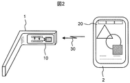
- FIG. 2 is a schematic diagram of each of the head mounted display device 1 and the portable information input / output device 2 in the present embodiment shown in FIG.
- the head mounted display device 1 includes a first video display unit 10 that displays a predetermined video (hereinafter, this video is referred to as a first video) within the visual field of the operator when the head mounted display device 1 is worn on the head.
- the first video display unit 10 includes, for example, a video display device including a dedicated liquid crystal element or a minute movable mirror element arranged in a grid pattern, and the first video displayed on the video display device within the visual field of the operator.
- the present embodiment is not limited to this.
- the portable information input / output device 2 includes a second video display unit 20 that displays a second video that is completely independent of the first video (hereinafter, this video is referred to as a second video). Yes.
- the second video display unit 20 also has a function of an input device for inputting a predetermined information signal by a predetermined input operation.
- this input device for example, when an operator's finger touches the display screen of the second video display unit 20, information using a so-called touch panel function that detects the contact position of the finger, its moving direction, distance, and the like is used.
- a voice input device for inputting predetermined information may be used.
- the portable information input / output device 2 has a function of transmitting a predetermined information signal 30 to the head mounted display device 1 wirelessly or by wire, and the head mounted display device 1 receives the information signal 30. It has a function.
- a portable information input / output device having the above-described video display function
- an information input device function using a touch panel for example, a tablet-type portable personal computer or a so-called smartphone
- an information signal transmission function for example, a tablet-type portable personal computer or a so-called smartphone
- a portable information communication terminal device represented by
- the present embodiment is not limited to this, and any form of portable information input / output device having the video display function, the information input device function, and the information signal transmission function as described above may be used. It does n’t matter.
- any detection means such as a means for detecting the contact pressure of the finger on the panel or a means for detecting a change in capacitance may be used as the detection means for the finger touch position in the touch panel function. Absent.
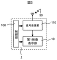
- FIG. 3 is a schematic configuration block diagram of the head mounted display device 1 in the present embodiment. That is, in FIG. 3, in the head mounted display device 1, a signal receiving unit 110 that receives an information signal 30 transmitted from the portable information input / output device 2 and a predetermined image received by the signal receiving unit 110. A first video display unit 10 that displays a first video using an information signal is provided. Processing operations in these units are controlled by the control unit 100.
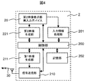
- FIG. 4 is a schematic configuration block diagram of the portable information input / output device 2 in the present embodiment.
- the portable information input / output device 2 includes a first video generation unit 211 for generating a first video displayed on the head mounted display device 1, and a first video generated by the first video generation unit 211.
- a signal transmission unit 210 that converts a video signal of a video into a predetermined information signal 30 and transmits the signal to the head mounted display device 1, and a second for generating a second video displayed on the portable information input / output device 2.
- a video generation unit 221 and a second video display unit 20 that displays video using the video signal generated by the second video generation unit 221 are provided.
- the second video display unit 20 also has a predetermined input device function such as a touch panel, and a predetermined information signal or control signal input from the input device is input to the input information processing unit 201 in a predetermined manner. Converted to video editing signal.
- the portable information input / output device 2 also includes a storage unit 202 having a function of storing each video information generated by the first video generation unit 211 or the second video generation unit 221. These processing operations are controlled by the control unit 200.
- the video editing signal is reflected in the first video displayed on the head mounted display device 1, or The operator can freely determine whether to reflect in the second video displayed on the portable information input / output device 2 or in both the first and second video generation.
- the video editing signal is sent to one or both of the first video generation unit 211 and the second video generation unit 221, and is generated by each generation unit. Reflected in the video.
- the first video generated by the portable information input / output device 2 and displayed by the head-mounted display device 1 and the second video displayed by the portable information input / output device 2 are coherent with each other. It can be displayed as a totally independent video.
- the input information signal input from the second video display unit / input device of the portable information input / output device 2 is reflected only in the generation of the first video displayed on the head mounted display device 1 or is portable. The operator can freely select and switch whether to reflect only the generation of the second video displayed on the type information input / output device 2 or to both the first and second video generations. .
- FIG. 5 is a diagram for explaining one use case in the present embodiment. 5, the same components as those in FIGS. 1 and 2 are denoted by the same reference numerals.
- the video displayed on the first video display unit 10 of the head mounted display device 1 and the video displayed on the second video display unit 20 of the portable information input / output device 2 are completely different.
- the second video display unit 20 also has a touch panel function as described above.
- the touch panel has a function of detecting the relative position of a detection target in contact with the panel, and is detected by the touch panel.
- the positional information and the like of the contact finger 4 is incorporated into the information signal 30 as an information signal or a video editing signal that is a control signal, and transmitted to the head mounted display device 1.
- a cursor 5 having a predetermined shape, which is a predetermined auxiliary video is superimposed on the video displayed on the first video display unit 10 and reflected in the position information.
- the cursor 5 moves within the display video of the first video display unit 10 according to the movement of the finger 4 that is in contact with the touch panel of the second video display unit 20 (for example, the locus 41 in the figure). It moves like the locus
- a predetermined switching operation, a video selection operation, a drag or drop operation, or the like is executed only on the display video of the first video display unit 10 due to a change in contact pressure or the like. That is, the display form of the first video, such as display content, color, size, orientation, and area, can be changed by changing the contact pressure.
- the position information of the contact finger 4 detected by the touch panel has no influence on the second image displayed on the second image display unit 20.
- the operator can be seen by others on the display screen of the portable information input / output device 2. While displaying the public video content that does not matter as the second video, it is possible to display on the head mounted display device 1 the video content with high secrecy that is not desired to be seen by others as the first video.
- the displayed first video can be created or edited.
- the first image and / or the second image created and edited, or both can be stored in the storage unit 202 of the portable information input / output device 2 independently.
- FIG. 6 is a diagram for explaining another use case in the present embodiment.
- the same components as those in FIGS. 1, 2 and 5 are denoted by the same reference numerals.
- a video of a predetermined keyboard is displayed on the second video display unit / touch panel 20 of the portable information input / output device 2. Then, for example, as shown by a trajectory 41 in the figure, the operator sequentially touches each section on which characters, numbers, symbols, or the like in the keyboard are displayed with the finger 4 so that the characters, numbers in the section are displayed. Alternatively, a symbol is selected and displayed as a predetermined character string 52 on the first video display unit 10 of the head mounted display device 1.
- the operator can create or edit a highly confidential document or content without being seen by others on the display screen of the head mounted display device 1, and has a wide display area. Since the entire display screen and touch panel of the portable information input / output device 2 can be operated as a keyboard, the usability is dramatically improved as compared with the conventional case.
- the display of the first video displayed on the head mounted display device 1 based on the position information of the detection target or the information of the contact pressure obtained from the second video display unit / input device of the portable information input / output device 2 Switching between changing the form or changing the display form of the second video displayed on the portable information input / output device 2 may be performed.
- the display screen / touch panel of the portable information input / output device 2 is divided into an area A for the head mounted display device and an area B for the portable information input / output device, and the input in the area A is sent to the head mounted display device.
- the input in the region B may be reflected to the portable information input / output device.
- the first video generation unit 211 and the second video generation unit 221 are included in the portable information input / output device 2 in order to more clearly represent the independence of the first video and the second video.
- the present embodiment is not limited to this, and a configuration in which a single video generation unit generates a video image as long as the independence of the first video and the second video can be ensured. It does not matter.
- the first video generation unit 211 may simply be converted into a video signal based on information from the outside, or simply through. For example, it may be configured to convert to a video signal based on information obtained on the Internet, or to mediate that information to a signal transmission unit.
- the portable information input / output device 2 includes the storage unit 202 that stores the video information of the first video or the second video.
- the head mounted display device is not limited, for example, the first video or the second video is stored in an external storage medium by a predetermined communication function, or the necessary video information is extracted from the predetermined external storage medium.
- the storage unit 202 in the portable information input / output device 2 may be omitted by providing a function to be displayed on the mobile information input / output device 1 or the portable information input / output device 2.
- this embodiment is a wearable information display / input system including a wearable display device, and a portable information input / output device including a display screen for displaying video information and an input device.
- the information input / output device includes a signal transmission unit that transmits an information signal or a control signal input from the input device to the wearable display device, and the wearable display device includes an information signal or a signal transmitted from the portable information input / output device.
- a portable information input / output device includes a signal receiving unit that receives a control signal and a video display unit that displays predetermined video information based on an information signal or a control signal obtained by the signal receiving unit.
- a first video generation unit for generating a first video to be displayed on the device, and a first video to be displayed on the portable information input / output device
- the input device of the portable information input / output device has an input operation panel that also serves as a display screen, and has a function of detecting the relative position of a detection target that touches the input operation panel.
- the information signal or control signal transmitted to the device includes the position information of the detection target that touches the input operation panel, and the video display unit in the wearable display device includes the position information of the detection target that touches the input operation panel. And a function of superimposing and displaying an auxiliary image on the image displayed on the wearable display.
- the input device has a function of detecting a contact pressure of a detection target that contacts the input operation panel, and an information signal or a control signal transmitted from the signal transmission unit to the wearable display device contacts the input operation panel.
- a video display unit in the wearable display device includes a first information displayed on the wearable display device based on the information on the detection target contact pressure included in the information signal or the control signal. It has a function to change the video display form.
- the portable information input / output device changes the display form of the first video displayed on the wearable display device based on the position information of the detection target obtained from the input device or the information on the contact pressure of the detection target.
- a function of switching between a first input state and a second input state that changes the display form of the second video displayed on the display screen of the portable information input / output device is provided.
- a portable information input / output device having a display screen for displaying video information and an input device, wherein the signal transmission unit transmits an information signal or a control signal input from the input device to the wearable display device
- a first video generation unit that generates a first video displayed on the wearable display device, and a second video generation that generates a second video independent of the first video displayed on the portable information input / output device It consists of parts.
- An information input method for a wearable display device in a wearable information display input system comprising a wearable display device, and a portable information input / output device including a display screen for displaying video information and an input device, Based on information input from an input device of a portable information input / output device separate from the wearable display device, the portable information input / output device generates a first video to be displayed on the wearable display device.
- the input information and the first video are independent and have no influence on the second video used in the type information input / output device, and the input information and the first video are transmitted to the wearable display device.
- the first image is displayed on the wearable display device, and the input information is the wearable type. And information input of Isupurei devices.
- the wearable information display system in the wearable information display system, it is possible to provide an information input means and apparatus having simple means and high operability and convenience.
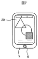
- FIG. 7 is a schematic diagram of a portable information input / output device according to the present embodiment. 7, the same components as those in FIG. 2 are denoted by the same reference numerals.
- a predetermined photographing device 6 is provided on the same side as the display screen of the second video display unit 20 in the portable information input / output device 7.
- the photographing device 6 is an electronic camera device including, for example, a predetermined electronic imaging element and a predetermined photographing lens, and has a function of photographing at least the entire face of the operator.
- FIG. 8 is a schematic block diagram of the portable information input / output device 7 in this embodiment.
- the same components as those in FIG. 4 are denoted by the same reference numerals.
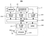
- the portable information input / output device 7 includes the photographing device 6 and the line-of-sight direction detection unit 230, and each processing operation is controlled by the control unit 200. Yes.
- the line-of-sight direction detection unit 230 is a line-of-sight direction detection circuit having a function of detecting in which direction the line of sight of the operator is directed from the entire image of the operator's face or a part of the image captured by the photographing device 6. .
- a means for detecting the gaze direction from the orientation of the face or the relative position of the pupil (black eye) with respect to the eye contour does not limit such line-of-sight detection means.
- any detection means can be used as long as it can detect whether or not the operator's line of sight is facing the display screen direction of the portable information input / output device 7. You may use.
- the head mounted display device 1 may use the same device as that of the first embodiment described with reference to FIGS.
- FIG. 9 shows a process flowchart executed by the portable information input / output device 7 in this embodiment.
- step 301 the entire face or a part of the operator's face is photographed by the photographing device 6 incorporated in the portable information input / output device 7 as described above.
- step 302 the photographed image of the operator is sent to the gaze direction detector 230, where the gaze direction of the operator is detected.
- step 303 it is determined whether or not the detected operator's line of sight faces the display screen direction of the portable information input / output device 7.
- the video display of the first video display unit 10 in the head mounted display device 1 is turned off (turned off) in the next step 304, and the subsequent step 305.
- the screen display of the second video display unit 20 in the portable information input / output device 7 is turned on (lighted).
- step 306 the video display of the first video display unit 10 in the head mounted display device 1 is turned on (lit), In 307, the screen display of the second video display unit 20 in the portable information input / output device 7 is turned OFF (extinguishes).
- step 308 By repeating the above flow until it is determined in step 308 that a predetermined end signal has been input ([Yes]), if the operator is watching the display screen of the portable information input / output device 7, automatic Only the display screen is turned on and the display screen in the head-mounted display device 1 is turned off. On the other hand, when the operator is not gazing at the display screen of the portable information input / output device 7, it is automatically carried. The display screen of the type information input / output device 7 is turned off, and the operation of turning on the display screen in the head mounted display device 1 is repeated.
- steps 304 and 305 and 306 and 307 in FIG. 9 may be changed.
- the display luminance may be increased and the display luminance of the other may be decreased.
- the rise time from the low luminance state to the high luminance state is earlier than the rise time from the display OFF state to the ON state during the display ON / OFF control.
- FIG. 12 shows another embodiment of a flowchart executed by the portable information input / output device 7 in the present embodiment. 12, the same components as those in the flowchart shown in FIG. 9 are denoted by the same reference numerals.
- step 301 the entire face of the operator or a part thereof is photographed by the photographing device 6 incorporated in the portable information input / output device 7, and then in step 302.
- step 309 a predetermined information signal is captured from the second video display unit / input device (for example, touch panel) 20 in the portable information input / output device 7.
- the input information signal is converted into a predetermined video editing signal.
- step 303 it is determined whether or not the operator's line of sight detected in step 303 is facing the display screen direction of the portable information input / output device 7, and if the determination is [Yes], that is, the operator is mobile. If it is determined that the display screen of the type information input / output device 7 is being watched, the video editing signal is sent to the second video display unit 20 in the portable information input / output device 7 in the next step 311. It is reflected only on the displayed second video. That is, only the display form of the second video is changed by the video editing signal. At this time, the video editing signal has no influence on the first video displayed on the first video display unit 10 in the head mounted display device 1.
- step 303 determines whether the operator is not gazing at the display screen of the portable information input / output device 7. If the determination in step 303 is [No], that is, if it is determined that the operator is not gazing at the display screen of the portable information input / output device 7, the process jumps to step 312 and the video editing signal is sent to the first video editing signal.
- the video editing signal reflects only one video, and the video editing signal does not affect the second video. That is, only the display form of the first video is changed by the video editing signal.
- input information from the touch panel is displayed as a first image displayed on the head-mounted display device 1 or a second image displayed on the portable information input / output device 7. It is no longer necessary for the operator to determine each time whether the change is reflected or not, and it can be automatically reflected on the screen that matches the operator's intention, greatly improving the convenience for the operator. improves.
- the portable information input / output device includes the gaze detection unit that detects the gaze direction of the operator holding the portable information input / output device, and includes the gaze direction information detected by the gaze detection unit. Based on this, a function of automatically switching on and off of each of the first video displayed on the wearable display device and the second video displayed on the display screen of the portable information input / output device is provided.
- the display brightness of the first video displayed on the wearable display device and the display brightness of the second video displayed on the display screen of the portable information input / output device based on the gaze direction information detected by the gaze detection means. It has a function to change automatically.
- the first input state for changing the display form of the first video displayed on the wearable display device and the display screen of the portable information input / output device based on the visual line direction information detected by the visual line detection means A function of switching between a second input state for changing the display form of the second video to be displayed is provided.
- FIG. 13 is a flowchart showing an authentication process in the head mounted display device 1 in this embodiment.
- the portable information input / output device 2 stores an individual identification code (hereinafter referred to as a first identification code) for each device for individual identification of the portable information input / output device.
- a first identification code an individual identification code for each device for individual identification of the portable information input / output device.
- an information signal corresponding to the first identification code is incorporated in the information signal 30 and transmitted to the head mounted display 1.
- control unit 100 of the head-mounted display device 1 has the first identification code information regarding the portable information input / output device 2 properly assigned to the head-mounted display device and the individual head-mounted display devices 1.
- the assigned second identification code information or predetermined password information is registered in advance.
- step 401 the information signal 30 transmitted from the portable information input / output device 2 to the head mounted display device 1 is received by the signal receiving unit 110 in the head mounted display device 1 and included therein. First identification code information is sent to the control unit 100.
- step 402 the first identification code signal sent to the control unit 100 is collated with the identification code of the portable information input / output device 2 properly assigned to each head-mounted display device 1 described above. , It is determined whether the codes match.
- step 406 the head mounted display device 1 is put into an inoperable state.
- step 403 the operator 3 inputs a predetermined second identification code or password from the second video display unit / input device 20 in the portable information input / output device 2.
- the input second identification code or password information is also incorporated into the information signal 30 in the same manner as the first identification code information, and is sent to the control unit 100 in the head mounted display device 1.
- step 404 whether the identification code or password entered by the operator is matched with the legitimate second identification code or password information that is collated with the legitimate second identification code or password information registered in advance. Is determined.
- step 406 the operator is regarded as not a valid user (user) and jumps to step 406 as in the case of the first identification code, and the head mounted display device 1 is inoperable. The process to make is done. On the other hand, if the determination result is [Yes], in step 405, the process for bringing the head mounted display device 1 into the operating state is performed for the first time.
- the embodiment in which the operator inputs the second identification code or the password for so-called user authentication for authenticating the operator as a user (user) has been described.
- the embodiment is not limited to this, and any user authentication means may be used.
- a device capable of fingerprint authentication or vein authentication may be incorporated in the portable information input / output device 2 and user authentication may be performed by the fingerprint authentication or vein authentication.
- User authentication may be performed by incorporating a voice input device and voiceprint authentication using the voice input device.
- authentication such as biometric authentication using the eye of the operator such as retina authentication and iris authentication, or so-called jas chair authentication that performs authentication using the movement and combination of the operator's fingers User authentication may be performed using the means.
- security performance can be further improved by using such advanced authentication means.
- the present embodiment identifies individual portable information input / output devices from information signals or control signals transmitted from the signal transmission unit of the portable information input / output devices to the wearable display device.
- the first identification code information and the second identification code information or password information input from the input device by the operator, and the wearable display device is valid from the first identification code information to the portable information input / output device.
- a function of putting the wearable display device in an operating state by authenticating that the device is a device and authenticating that the operator is a valid user from the second identification code information or the password information is provided. Thereby, security performance can be improved.
- each of the above-described configurations, functions, processing units, processing means, and the like may be realized by hardware by designing a part or all of them with, for example, an integrated circuit.
- Each of the above-described configurations, functions, and the like may be realized by software by interpreting and executing a program that realizes each function by the processor.
Landscapes
- Engineering & Computer Science (AREA)
- Theoretical Computer Science (AREA)
- Computer Security & Cryptography (AREA)
- General Engineering & Computer Science (AREA)
- Physics & Mathematics (AREA)
- General Physics & Mathematics (AREA)
- Computer Hardware Design (AREA)
- Software Systems (AREA)
- Human Computer Interaction (AREA)
- User Interface Of Digital Computer (AREA)
Abstract
ウェアラブル型の情報表示および入力システムにおいて、簡便でかつ高い操作性、利便性の有する情報入力手段や高いセキュリティ性能を提供することを目的とする。 そのために、操作者はヘッドマウントディスプレイ装置を頭部に装着すると同時に、所定の携帯型情報入出力装置を把持する。前記ヘッドマウントディスプレイ装置で表示される第1の映像と前記携帯型情報入出力装置で表示される第2の映像は共に前記携帯型情報入出力装置内で生成されるが、各映像は完全に独立している。また前記携帯型情報入出力装置内のタッチパネル等の入力デバイスから入力された情報信号を、前記第1の映像または前記第2の映像のどちらの映像の編集に反映するかは操作者が自由に選択もしくは操作者の視線方向により自動的に切り替える機能を備える。
Description
本発明は、ウェアラブル型ディスプレイ装置の情報表示入力システムに関する。
近年、ゴーグル型や眼鏡型のヘッドマウントディスプレイ装置等を用いて所定の映像情報を表示する、いわゆるウェアラブル型ディスプレイ装置の情報表示システムが急速に普及しつつある。このようなウェアラブル型情報表示システムにおいて、所定の情報を該システムに入力するための情報入力手段として、例えば、特開2000-242394号公報(特許文献1)がある。特許文献1では、ヘッドマウントディスプレイ装置等の表示デバイスによって空間上に仮想キーボードを表示させ、この仮想キーボードを操作する指先の位置や動きを指先に取り付けたセンサにより検知することで所定の情報を入力する情報入力手段が記載されている。
しかしながら、特許文献1に記載された情報入力手段では、仮想キーボードを操作する指先の位置や動きを検知するための指先センサ等を別途具備する必要があり、システムが大型化、複雑化する問題がある。また、指先センサ等の検知精度によりその操作性が大きく阻害されるという問題があった。
本発明はこれらの課題に鑑みなされたものであって、小型軽量なウェアラブル型情報表示システムにおいて、簡便な手段で、かつ高い操作性、利便性を有する情報入力手段または装置を提供することを目的とする。
上記課題を解決するために、例えば請求の範囲に記載の構成を採用する。本発明は上記課題を解決する手段を複数含んでいるが、その一例を挙げるならば、ウェアラブル型ディスプレイ装置と、映像情報を表示する表示画面と入力デバイスとを備えた携帯型情報入出力装置とからなるウェアラブル型情報表示入力システムであって、携帯型情報入出力装置は前記入力デバイスから入力された情報信号または制御信号をウェアラブル型ディスプレイ装置に向けて発信する信号送信部を備え、ウェアラブル型ディスプレイ装置は携帯型情報入出力装置から発信された情報信号または制御信号を受信する信号受信部と該信号受信部で得られた情報信号または制御信号に基づいて所定の映像情報を表示する映像表示部とを備え、携帯型情報入出力装置は、ウェアラブル型ディスプレイ装置に表示する第1の映像を生成する第1映像生成部と、携帯型情報入出力装置に表示する第1の映像と独立した第2の映像を生成する第2映像生成部を有する構成とする。
本発明によれば、ウェアラブル型情報表示システムにおいて、簡便な手段でかつ高い操作性、利便性を有する情報入力手段および装置を提供することができる。
以下、図面を用いて本発明の実施例について説明する。
図1は、本実施例におけるウェアラブル型情報表示および入力システムの概略図である。図1において、ヘッドマウントディスプレイ装置1は、操作者3の頭部に装着され、外界が視認可能な状態でユーザの視野内の一部に映像を表示させる機能を備えた、いわゆるシースルー型のヘッドマウントディスプレイ装置である。なお、このヘッドマウントディスプレイ装置1は、本実施例に示すシースルー型ヘッドマウントディスプレイ装置に限定されるものでは無く、操作者の身体のいずれかに装着して操作者に対し所定の映像を表示する機能を備えた、いわゆるウェアラブル型のディスプレイ装置であればどのような形態のものでも構わない。
また、操作者3は、ヘッドマウントディスプレイ装置1とは別に携帯型の情報入出力装置2を把持している。本実施例におけるウェアラブル型情報表示および入力システムは、基本的にこの携帯型情報入出力装置2とヘッドマウントディスプレイ装置1の組合せによって構成される。
図2は、図1に示した本実施例におけるヘッドマウントディスプレイ装置1と携帯型情報入出力装置2それぞれの概略図である。
ヘッドマウントディスプレイ装置1は、頭部に装着した場合に操作者の視野内に所定の映像(以下、この映像を第1映像と記す。)を表示する第1映像表示部10を備えている。この第1映像表示部10は、例えば専用の液晶素子あるいは格子状に配置された微小可動ミラー素子等からなる映像表示機と、この映像表示機で表示された第1映像を操作者の視野内に投影するための所定の光学系などから構成されるものが一般的であるが、本実施例はそれに限定されるものではない。
一方、携帯型情報入出力装置2は、第1映像に対して完全に独立した第2の映像(以下、この映像を第2映像と記す。)を表示する第2映像表示部20を備えている。またこの第2映像表示部20は、所定の入力操作により所定の情報信号を入力する入力デバイスの機能も兼備している。この入力デバイスとしては、例えば第2映像表示部20の表示画面上に操作者の手指が接触した場合に、その手指の接触位置およびその移動方向、距離などを検知するいわゆるタッチパネル機能を用いた情報入力デバイスなどがある。以下の説明ではそのようなタッチパネルによる情報入力デバイスを前提に実施例の説明を進めるが、本実施例は、そのようなタッチパネルによる情報入力デバイスに限定されるものではなく、例えば、操作者の音声により所定の情報入力を行う音声入力デバイスでも構わない。
また、携帯型情報入出力装置2は、所定の情報信号30を無線もしくは有線にてヘッドマウントディスプレイ装置1に向けて発信する機能を備え、ヘッドマウントディスプレイ装置1は、この情報信号30を受信する機能を備えている。
なお、以上のような映像表示機能、タッチパネル等による情報入力デバイス機能、および情報信号発信機能を備えた携帯型情報入出力装置の実例としては、例えばタブレット型の携帯型パーソナルコンピュータ、あるいは、いわゆるスマートフォンに代表されるような携帯型情報通信端末装置がある。しかしながら、本実施例はそれに限定されるものでは無く、前記したような映像表示機能、情報入力デバイス機能、および情報信号発信機能を備えた携帯型の情報入出力装置であればどのような形態のものでも構わない。
また、前記タッチパネル機能における手指の接触位置等の検知手段についても、例えば手指のパネルへの接触圧力を検知する手段や静電容量の変化を検知する手段等どのような検知手段を用いても構わない。
図3は、本実施例におけるヘッドマウントディスプレイ装置1の概略構成ブロック図である。すなわち、図3において、ヘッドマウントディスプレイ装置1内には、携帯型情報入出力装置2から発信された情報信号30を受信する信号受信部110や、この信号受信部110で受信された所定の映像情報信号を用いて第1映像の表示を行う第1映像表示部10が具備されており、これら各部での処理操作は制御部100によってコントロールされる構成になっている。
図4は、本実施例における携帯型情報入出力装置2の概略構成ブロック図である。図4において、携帯型情報入出力装置2は、ヘッドマウントディスプレイ装置1で表示される第1映像を生成するための第1映像生成部211、該第1映像生成部211で生成された第1映像の映像信号を所定の情報信号30に変換してヘッドマウントディスプレイ装置1に向けて送信する信号送信部210、携帯型情報入出力装置2で表示される第2映像を生成するための第2映像生成部221および該第2映像生成部221で生成された映像信号を用いて映像を表示する第2映像表示部20を備えている。
また、前記したように第2映像表示部20はタッチパネル等所定の入力デバイス機能も兼備しており、この入力デバイスから入力された所定の情報信号または制御信号は、入力情報処理部201で所定の映像編集信号に変換される。
さらに、携帯型情報入出力装置2には、第1映像生成部211または第2映像生成部221で生成される各映像情報を記憶する機能を備えた記憶部202も具備されており、各部での処理操作は制御部200によってコントロールされている。
ところで、第2映像表示部兼入力デバイスから入力され入力情報処理部201で変換された映像編集信号に関しては、この映像編集信号をヘッドマウントディスプレイ装置1で表示される第1映像に反映させるか、携帯型情報入出力装置2で表示される第2映像に反映させるか、あるいは第1および第2の両方の映像生成に反映させるかについて、操作者が自由に判断して切り替えることが出来る。つまり操作者が所定の切り替え操作を行うことで、映像編集信号は第1映像生成部211または第2映像生成部221のどちらか一方、あるいはその両方に送られ、それぞれの生成部で生成される映像に反映される。
本実施例における主要な特徴を改めて整理すると、
(1)携帯型情報入出力装置2で生成された、ヘッドマウントディスプレイ装置1で表示される第1映像と、携帯型情報入出力装置2で表示される第2映像は、互いに干渉性を持たない全く独立した映像として表示できる。
(2)携帯型情報入出力装置2の第2映像表示部兼入力デバイスから入力された入力情報信号は、ヘッドマウントディスプレイ装置1で表示される第1映像の生成にだけ反映されるか、携帯型情報入出力装置2で表示される第2映像の生成にだけ反映されるか、あるいは第1および第2の両方の映像生成に反映させるかを操作者が自由に選択して切り替えることができる。
以上の2点である。
(1)携帯型情報入出力装置2で生成された、ヘッドマウントディスプレイ装置1で表示される第1映像と、携帯型情報入出力装置2で表示される第2映像は、互いに干渉性を持たない全く独立した映像として表示できる。
(2)携帯型情報入出力装置2の第2映像表示部兼入力デバイスから入力された入力情報信号は、ヘッドマウントディスプレイ装置1で表示される第1映像の生成にだけ反映されるか、携帯型情報入出力装置2で表示される第2映像の生成にだけ反映されるか、あるいは第1および第2の両方の映像生成に反映させるかを操作者が自由に選択して切り替えることができる。
以上の2点である。
次に、上記の特徴およびその効果について、具体的な使用事例を示して説明する。
図5は本実施例における一使用事例を説明する図である。図5において、図1および図2と同じ構成部品には同じ符号を付している。
図5において、ヘッドマウントディスプレイ装置1の第1映像表示部10で表示されている映像と、携帯型情報入出力装置2の第2映像表示部20に表示される映像は全く異なっている。そして、この第2映像表示部20は、前記したようにタッチパネル機能も兼備しているが、このタッチパネルはパネルに接触する検出対象の相対位置を検知する機能を備えており、このタッチパネルによって検知された接触手指4の位置情報等は、情報信号または制御信号である映像編集信号として情報信号30内に組み込まれてヘッドマウントディスプレイ装置1に送信される。そして、第1映像表示部10に表示された映像内に所定の補助映像である所定形状のカーソル5が重畳表示され、その位置情報に反映される。
すなわち、このカーソル5は、第2映像表示部20のタッチパネルに接触している手指4の動き(例えば図中の軌跡41)に応じて第1映像表示部10の表示映像内を、例えば図中の軌跡51のように移動する。さらに、例えば、接触圧の変化などによって第1映像表示部10の表示映像に対してのみ所定のスイッチング操作や、映像の選択操作、ドラックあるいはドロップ操作などが実行される。すなわち、接触圧の変化などによって、第1映像の、表示内容、色、大きさ、向き、領域などの表示形態を変化させることが出来る。
一方、タッチパネルで検知された接触手指4の位置情報等は、第2映像表示部20で表示されている第2映像には全く影響を与えない。
ヘッドマウントディスプレイ装置1および携帯型情報入出力装置2に上記のような機能を持たせることにより、例えば、操作者は、携帯型情報入出力装置2の表示画面上には他人に見られても構わない公開映像コンテンツを第2映像として表示させる一方で、他人に見られたくない秘匿性の高い映像コンテンツを、第1映像としてヘッドマウントディスプレイ装置1に表示させることが出来る。
更に第1映像を参照しながら、同時に携帯型情報入出力装置2の表示画面兼タッチパネルを手指4で操作することで前記したタッチパネルによる情報入力操作を行い、その入力情報をもってヘッドマウントディスプレイ装置1に表示させた第1映像の創作あるいは編集を行うことが出来る。
そして、創作、編集された第1映像または第2映像、あるいはその両方を携帯型情報入出力装置2の記憶部202にそれぞれ独立に記憶させることが出来る。
図6は、本実施例における他の使用事例を説明する図である。本図において図1、図2および図5と同じ構成部品には同じ符号を付している。
図6において、携帯型情報入出力装置2の第2映像表示部兼タッチパネル20には所定のキーボードの映像が表示されている。そして、例えば操作者が、図中の軌跡41が示すように、このキーボード内の文字、数字または記号等が表示されている各区画を手指4で順次タッチすることで、その区画の文字、数字または記号が選択され、これがヘッドマウントディスプレイ装置1の第1映像表示部10に所定の文字列52として表示される。
このような機能を持たせることにより、操作者は秘匿性の高い書類またはコンテンツをヘッドマウントディスプレイ装置1の表示画面上で他人に見られることなく創作あるいは編集することが出来る上、表示面積が広い携帯型情報入出力装置2の表示画面兼タッチパネル全体をキーボードとして操作することが出来るので、従来に比べ使い勝手が飛躍的に向上する。
また、携帯型情報入出力装置2の第2映像表示部兼入力デバイスから得られた検出対象の位置情報または接触圧の情報に基づいて、ヘッドマウントディスプレイ装置1で表示される第1映像の表示形態を変化させるか、携帯型情報入出力装置2で表示される第2映像の表示形態を変化させるかの切替えを行っても良い。
また、携帯型情報入出力装置2の表示画面兼タッチパネルを、ヘッドマウントディスプレイ装置用の領域Aと携帯型情報入出力装置用の領域Bに分割し、領域Aでの入力はヘッドマウントディスプレイ装置に反映され、領域Bでの入力は携帯型情報入出力装置に反映されるようにしても良い。これにより、切り替えることなく、携帯型情報入出力装置2の表示画面兼タッチパネルを用いてヘッドマウントディスプレイ装置と携帯型情報入出力装置の両方の編集を行うことが出来る。
なお、図4の概略ブロック図では、第1映像と第2映像の独立性をより明確に表すため、携帯型情報入出力装置2内に第1映像生成部211と第2映像生成部221を独立した別個の映像生成部として記載しているが、本実施例はこれに限定されるものでは無く、第1映像と第2映像の独立性が確保できれば、一つの映像生成部で生成する構成であっても構わない。また、第1映像生成部211は、外部からの情報をもとに単に映像信号に変換する、もしくは、単にスルーする構成であっても良い。例えば、インターネットで入手した情報を基に映像信号に変換するか、もしくはその情報を信号送信部へ送る仲介をする構成であっても良い。
また、図4の概略ブロック図では、携帯型情報入出力装置2内に第1映像または第2映像の映像情報を記憶する記憶部202を具備しているが、これも、このような構成に限定されるものではなく、例えば所定の通信機能によって外部の記憶媒体に第1映像または第2映像を記憶させ、あるいは逆に所定の外部記憶媒体から必要な映像情報を引き出して、ヘッドマウントディスプレイ装置1または携帯型情報入出力装置2に表示させるような機能を持たせることで、携帯型情報入出力装置2内の記憶部202を省略した構成であっても構わない。
以上のように本実施例は、ウェアラブル型ディスプレイ装置と、映像情報を表示する表示画面と入力デバイスとを備えた携帯型情報入出力装置とからなるウェアラブル型情報表示入力システムであって、携帯型情報入出力装置は入力デバイスから入力された情報信号または制御信号をウェアラブル型ディスプレイ装置に向けて発信する信号送信部を備え、ウェアラブル型ディスプレイ装置は携帯型情報入出力装置から発信された情報信号または制御信号を受信する信号受信部と該信号受信部で得られた情報信号または制御信号に基づいて所定の映像情報を表示する映像表示部とを備え、携帯型情報入出力装置は、ウェアラブル型ディスプレイ装置に表示する第1の映像を生成する第1映像生成部と、携帯型情報入出力装置に表示する第1の映像と独立した第2の映像を生成する第2映像生成部を有する構成とする。
また、携帯型情報入出力装置の入力デバイスは表示画面と兼用の入力操作パネルを備え、入力操作パネルに接触する検出対象の相対位置を検知する機能を備えており、信号送信部からウェアラブル型ディスプレイ装置に向けて発信される情報信号または制御信号は入力操作パネルに接触する検出対象の位置情報を含み、かつウェアラブル型ディスプレイ装置内の映像表示部は入力操作パネルに接触する検出対象の位置情報に基づいてウェアラブル型ディスプレイに表示される映像に補助映像を重畳表示させる機能を備える。
また、入力デバイスは入力操作パネルに接触する検出対象の接触圧を検知する機能を備えており、信号送信部からウェアラブル型ディスプレイ装置に向けて発信される情報信号または制御信号は入力操作パネルに接触する検出対象の接触圧の情報を含み、ウェアラブル型ディスプレイ装置内の映像表示部は情報信号または制御信号に含まれる検出対象の接触圧の情報に基づいてウェアラブル型ディスプレイ装置に表示される第1の映像の表示形態を変化させる機能を備える。
また、携帯型情報入出力装置は入力デバイスから得られた検出対象の位置情報または検出対象の接触圧の情報に基づいて、ウェアラブル型ディスプレイ装置に表示される第1の映像の表示形態を変化させる第1の入力状態と、携帯型情報入出力装置の表示画面に表示される第2の映像の表示形態を変化させる第2の入力状態とを切り替える機能を備える。
また、映像情報を表示する表示画面と入力デバイスとを備えた携帯型情報入出力装置であって、入力デバイスから入力された情報信号または制御信号をウェアラブル型ディスプレイ装置に向けて発信する信号送信部と、ウェアラブル型ディスプレイ装置に表示する第1の映像を生成する第1映像生成部と、携帯型情報入出力装置に表示する第1の映像と独立した第2の映像を生成する第2映像生成部とで構成される。
また、ウェアラブル型ディスプレイ装置と、映像情報を表示する表示画面と入力デバイスとを備えた携帯型情報入出力装置とからなるウェアラブル型情報表示入力システムにおけるウェアラブル型ディスプレイ装置の情報入力方法であって、ウェアラブル型ディスプレイ装置とは別体の携帯型情報入出力装置の入力デバイスから入力した情報をもとに、ウェアラブル型ディスプレイ装置に表示する第1の映像を携帯型情報入出力装置で生成し、携帯型情報入出力装置で用いる第2の映像に対して、入力した情報および第1の映像は独立し影響を与えないものであり、入力した情報および第1の映像を前記ウェアラブル型ディスプレイ装置に送信して、ウェアラブル型ディスプレイ装置で第1の映像を表示し、入力した情報をウェアラブル型ディスプレイ装置の情報入力とする。
これにより、本実施例によれば、ウェアラブル型情報表示システムにおいて、簡便な手段でかつ高い操作性、利便性を有する情報入力手段および装置を提供することができる。
図7は、本実施例における携帯型情報入出力装置の概略図である。図7において、図2と同じ構成部品には同じ符号を付している。
本実施例では、携帯型情報入出力装置7内の第2映像表示部20の表示画面と同じ側に所定の撮影装置6を具備している。この撮影装置6は、例えば所定の電子撮像素子と所定の撮影用レンズからなる電子カメラ装置で、少なくとも操作者の顔面全体または一部を撮影できる機能を備えている。
図8は、本実施例における携帯型情報入出力装置7の概略構成ブロック図である。図8において、図4の構成要素と同じ構成要素には同じ符号を付している。
本実施例では、携帯型情報入出力装置7内に図4に示した各要素に加えて、撮影装置6と視線方向検知部230が具備され、共に制御部200により各処理操作がコントロールされている。
視線方向検知部230は、撮影装置6で撮影した操作者の顔面全体またはその一部の映像から、操作者の視線がどの方向を向いているかを検知する機能を備えた視線方向検知回路である。このように視線方向を検知するには、例えば顔面の向きやあるいは眼の輪郭に対する瞳(黒目)の相対位置などからその視線方向を検知する手段等いくつかの公知手段があるが、本実施例はそのような視線検知手段に制限を加えるものではなく、後述するように操作者の視線が携帯型情報入出力装置7の表示画面方向を向いているか否かが検知できればどのような検知手段を用いても構わない。
なお、本実施例においては、ヘッドマウントディスプレイ装置1は図2および図3で説明した実施例1と同じ装置を用いて構わない。
図9は、本実施例における携帯型情報入出力装置7で実行される処理フローチャートを示している。
図9において、まずステップ301において、前記したように携帯型情報入出力装置7内に組み込まれた撮影装置6により操作者の顔面全体または一部が撮影される。
次にステップ302において、撮影された操作者の映像が視線方向検知部230に送られ、ここで操作者の視線方向が検知される。
そして、次のステップ303において、検知された操作者の視線が携帯型情報入出力装置7の表示画面方向に向いているか否かが判定される。
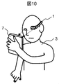
もしここで、操作者の視線が携帯型情報入出力装置7の表示画面方向に「向いている」すなわち[Yes]と判定された場合、つまり図10のように操作者3が携帯型情報入出力装置7の表示画面を注視していると判定された場合は、次のステップ304でヘッドマウントディスプレイ装置1内にある第1映像表示部10の映像表示をOFF(消灯)し、続くステップ305で携帯型情報入出力装置7内にある第2映像表示部20の画面表示をON(点灯)する。
一方、操作者の視線が携帯型情報入出力装置7の表示画面方向に「向いていない」すなわち[No]と判定された場合、つまり図11のように操作者3が携帯型情報入出力装置7の表示画面から視線を逸らしていると判定された場合は、ステップ306へ移行し、ここでヘッドマウントディスプレイ装置1内にある第1映像表示部10の映像表示をON(点灯)し、ステップ307で携帯型情報入出力装置7内にある第2映像表示部20の画面表示をOFF(消灯)する。
以上のフローをステップ308で所定の終了信号が入力された([Yes])と判定されるまで繰り返すことで、操作者が携帯型情報入出力装置7の表示画面を注視している場合は自動的にその表示画面のみが点灯し、ヘッドマウントディスプレイ装置1内の表示画面は消灯する一方で、操作者が携帯型情報入出力装置7の表示画面を注視していない場合は、自動的に携帯型情報入出力装置7の表示画面は消灯し、ヘッドマウントディスプレイ装置1内の表示画面の方が点灯する操作が繰り返される。
このような機能を持たせることにより、常に操作者が見たい画面のみが表示点灯し、見る意志の無い画面は自動的に消灯するので、操作者に視界を常に良好に保持できる上、消費電力の節約にも大きな効果が期待できる。
なお、図9におけるステップ304と305および306と307は、それぞれ処理の順番が入れ替わっても構わない。
また、図9の実施例では、ヘッドマウントディスプレイ装置1内の表示画面と携帯型情報入出力装置7の表示画面とどちらか一方のみ点灯し、他方を消灯する例を示したが、もちろんこれに限定されるものでは無く、例えば一方の表示輝度を上げ他方の表示輝度を下げるような処理をおこなっても構わない。この場合は、表示ON/OFF制御時の表示OFF状態からON状態への立ち上がり時間に比べて、低輝度状態から高輝度状態への立ち上がり時間が早くなるという利点がある。
図12は、本実施例における携帯型情報入出力装置7で実行されるフローチャートの別の一形態を示したものである。図12において、図9に示したフローチャート内の構成要素と同じ構成要素には同じ符号を付している。
図12においては、図9の例と同様、まずステップ301で携帯型情報入出力装置7内に組み込まれた撮影装置6によって操作者の顔面全体またはその一部が撮影され、次にステップ302で操作者の視線方向が検知されるが、それと同時にステップ309で携帯型情報入出力装置7内の第2映像表示部兼入力デバイス(例えばタッチパネル)20から所定の情報信号が取り込まれ、ステップ310において、この入力情報信号が所定の映像編集信号に変換される。
そして、図9と同様、ステップ303で検知された操作者の視線が携帯型情報入出力装置7の表示画面方向に向いているか否かが判定され、もし判定が[Yes]すなわち操作者が携帯型情報入出力装置7の表示画面を注視していると判定された場合は、次のステップ311で、前記した映像編集信号を携帯型情報入出力装置7内にある第2映像表示部20で表示される第2映像にのみ反映させる。すなわち、第2映像の表示形態のみを映像編集信号によって変化させる。この時、ヘッドマウントディスプレイ装置1内にある第1映像表示部10で表示される第1映像には前記映像編集信号は何の影響も与えない。
一方、ステップ303での判定が[No]すなわち操作者が携帯型情報入出力装置7の表示画面を注視していないと判定された場合は、ステップ312へ飛び、前記した映像編集信号を前記第1映像にのみ反映させ、前記第2映像には前記映像編集信号は何の影響も与えない。すなわち、第1映像の表示形態のみを映像編集信号によって変化させる。
このような自動切り換え機能を備えることで、タッチパネルからの入力情報をヘッドマウントディスプレイ装置1で表示される第1映像、あるいは携帯型情報入出力装置7で表示される第2映像、そのどちらの映像に反映させるかを操作者がいちいち判断して切り替え操作を行う必要が無くなり、自動的に操作者の意図に沿う方の画面に反映させることができるので、操作者にとっての利便性が飛躍的に向上する。
以上のように本実施例は、携帯型情報入出力装置は、携帯型情報入出力装置を保持する操作者の視線方向を検知する視線検知手段を備え、視線検知手段によって検出した視線方向情報に基づいてウェアラブル型ディスプレイ装置に表示される第1の映像と携帯型情報入出力装置の表示画面に表示される第2の映像の各々について点灯表示と消灯とを自動的に切り替える機能を備える。
また、視線検知手段によって検出した視線方向情報に基づいてウェアラブル型ディスプレイ装置に表示される第1の映像の表示輝度と携帯型情報入出力装置の表示画面に表示される第2の映像の表示輝度を自動的に変化させる機能を備える。
また、視線検知手段によって検出した視線方向情報に基づいて、ウェアラブル型ディスプレイ装置に表示される第1の映像の表示形態を変化させる第1の入力状態と、携帯型情報入出力装置の表示画面に表示される第2の映像の表示形態を変化させる第2の入力状態とを切り替える機能を備える。
これにより、本実施例によれば、常に操作者が見たい画面のみが表示点灯もしくは輝度を上げて表示、もしくは、編集が反映されるようにしたので、操作者の視界を常に良好に保持できる上、省電力にもなり、さらに、自動的に操作者の意図に沿う方の画面への編集の反映を実施でき、操作性が向上する。
図13は、本実施例におけるヘッドマウントディスプレイ装置1内での認証処理を示したフローチャートである。
本実施例においては、携帯型情報入出力装置2は、携帯型情報入出力装置の個別識別のために、装置ごとに個別の識別コード(これを第1識別コードと記す。)を記憶しており、かつ第1識別コードに相当する情報信号が情報信号30の中に組み込まれてヘッドマウントディスプレイ1に向けて発信されるようになっている。
一方、ヘッドマウントディスプレイ装置1の制御部100には、そのヘッドマウントディスプレイ装置に対して正当に割り付けられた携帯型情報入出力装置2に関する第1識別コード情報と、個々のヘッドマウントディスプレイ装置1に割り付けられた第2識別コード情報あるいは所定のパスワード情報があらかじめ登録されている。
そして、まずステップ401において、携帯型情報入出力装置2からヘッドマウントディスプレイ装置1に向けて送信された情報信号30は、ヘッドマウントディスプレイ装置1内の信号受信部110で受信され、そこに含まれる第1の識別コード情報が制御部100に送られる。
次にステップ402において、制御部100に送られた第1の識別コード信号が、前記した各ヘッドマウントディスプレイ装置1に対して正当に割り付けられた携帯型情報入出力装置2の識別コードと照合され、コードが一致するかどうかが判定される。
この時判定結果が[No]であれば、操作者はその頭部に装着しているヘッドマウントディスプレイ装置1に対して正当な組合せでは無い携帯型情報入出力装置2を把持していることになるので、正当な使用状態では無いと見なされステップ406へ移行し、ここでヘッドマウントディスプレイ装置1を稼動不能状態にする処理がなされる。
一方、前記判定結果が[Yes]ならば、次のステップ403に進む。このステップ403では、操作者3は携帯型情報入出力装置2内の第2映像表示部兼入力デバイス20から所定の第2識別コードあるいはパスワードを入力する。
この入力された第2識別コードあるいはパスワードの情報も第1識別コード情報と同じく情報信号30の中に組み込まれヘッドマウントディスプレイ装置1内の制御部100に送られる。
そして、ステップ404において、あらかじめ登録されている正当な第2識別コードあるいはパスワード情報と照合され、操作者によって入力された識別コードあるいはパスワードが、正当な第2識別コードあるいはパスワード情報と一致するかどうかか判定される。
この判定結果が[No]であれば、操作者は正当な使用者(ユーザ)では無いと見なして第1の識別コードの場合と同様にステップ406へ飛び、ヘッドマウントディスプレイ装置1を稼動不能状態にする処理がなされる。一方、判定結果が[Yes]ならば、ステップ405において初めてヘッドマウントディスプレイ装置1を稼動状態にする処理がなされる。
以上のように、第1識別コードおよび第2識別コード(またはパスワード)による2重の認証処理を行うことで、使用されるヘッドマウントディスプレイ装置1と携帯型情報入出力装置2の組合せの正当性と、操作者の使用者(ユーザ)としての正当性を共に認証することができるので、そのセキュリティ性能をより向上させることができる。
なお、前記実施例では、操作者の使用者(ユーザ)としての正当性を認証する、いわゆるユーザ認証のために、操作者が第2識別コードあるいはパスワードを入力する実施例について述べたが、本実施例はそれに限定されるものではなく、どのようなユーザ認証手段を用いても構わない。例えば、識別コードあるいはパスワードの入力の代わりに、指紋認証や静脈認証などが可能な装置を携帯型情報入出力装置2に組み込んで、その指紋認証や静脈認証によってユーザ認証を行ってもよいし、音声入力装置を組み込んでそれを用いた声紋認証でユーザ認証を行ってもよい。あるいは、内蔵の撮影装置を使って、網膜認証や虹彩認証などの操作者の眼を使った生体認証や、操作者の手指の動きや組合せの形等で認証を行ういわゆるジャスチェア認証などの認証手段を用いてユーザ認証を行っても構わない。本実施例においては、このような高度な認証手段を用いることで、さらにセキュリティ性能を向上させることができる。
以上のように本実施例は、携帯型情報入出力装置の信号送信部からウェアラブル型ディスプレイ装置に向けて発信される情報信号または制御信号には、個々の携帯型情報入出力装置を識別するための第1の識別コード情報と操作者が入力デバイスから入力した第2の識別コード情報またはパスワード情報とを含み、ウェアラブル型ディスプレイ装置は第1の識別コード情報から携帯型情報入出力装置が正当な装置であることを認証し、かつ第2の識別コード情報またはパスワード情報から操作者が正当なユーザであることを認証することでウェアラブル型ディスプレイ装置を稼動状態にする機能を備える。これにより、セキュリティ性能を向上させることができる。
なお、上記した実施例は本発明を分かりやすく説明するために詳細に説明したものであり、必ずしも説明した全ての構成を備えるものに限定されるものではない。また、ある実施例の構成の一部を他の実施例の構成に置き換えることが可能であり、また、ある実施例の構成に他の実施例の構成を加えることも可能である。また、各実施例の構成の一部について、他の構成の追加・削除・置換をすることが可能である。
また、上記の各構成、機能、処理部、処理手段等は、それらの一部又は全部を、例えば集積回路で設計する等によりハードウェアで実現しても良い。また、上記の各構成、機能等は、プロセッサがそれぞれの機能を実現するプログラムを解釈し、実行することによりソフトウェアで実現しても良い。
1…ヘッドマウントディスプレイ装置
2、7…携帯型情報入出力装置
3…操作者
4…操作者の手指
5…カーソル
6…撮影装置
10…第1映像表示部
20…第2映像表示部兼入力デバイス
30…送信信号
100、200…制御部
110…信号受信部
201…入力情報処理部
202…記憶部
210…信号送信部
211…第1映像生成部
221…第2映像生成部
230…視線方向検知部
2、7…携帯型情報入出力装置
3…操作者
4…操作者の手指
5…カーソル
6…撮影装置
10…第1映像表示部
20…第2映像表示部兼入力デバイス
30…送信信号
100、200…制御部
110…信号受信部
201…入力情報処理部
202…記憶部
210…信号送信部
211…第1映像生成部
221…第2映像生成部
230…視線方向検知部
Claims (14)
- ウェアラブル型ディスプレイ装置と、映像情報を表示する表示画面と入力デバイスとを備えた携帯型情報入出力装置とからなるウェアラブル型情報表示入力システムであって、
前記携帯型情報入出力装置は前記入力デバイスから入力された情報信号または制御信号を前記ウェアラブル型ディスプレイ装置に向けて発信する信号送信部を備え、
前記ウェアラブル型ディスプレイ装置は前記携帯型情報入出力装置から発信された前記情報信号または制御信号を受信する信号受信部と該信号受信部で得られた前記情報信号または制御信号に基づいて所定の映像情報を表示する映像表示部とを備え、
前記携帯型情報入出力装置は、前記ウェアラブル型ディスプレイ装置に表示する第1の映像を生成する第1映像生成部と、携帯型情報入出力装置に表示する前記第1の映像と独立した第2の映像を生成する第2映像生成部を有することを特徴とするウェアラブル型情報表示入力システム。 - 請求項1に記載のウェアラブル型情報表示入力システムであって、
前記携帯型情報入出力装置の入力デバイスは前記表示画面と兼用の入力操作パネルを備え、該入力操作パネルに接触する検出対象の相対位置を検知する機能を備えており、
前記信号送信部から前記ウェアラブル型ディスプレイ装置に向けて発信される情報信号または制御信号は前記入力操作パネルに接触する検出対象の位置情報を含み、かつ前記ウェアラブル型ディスプレイ装置内の映像表示部は前記入力操作パネルに接触する検出対象の位置情報に基づいて前記ウェアラブル型ディスプレイに表示される映像に補助映像を重畳表示させる機能を備えたことを特徴とするウェアラブル型情報表示入力システム。 - 請求項2に記載のウェアラブル型情報表示入力システムであって、
前記入力デバイスは前記入力操作パネルに接触する検出対象の接触圧を検知する機能を備えており、前記信号送信部から前記ウェアラブル型ディスプレイ装置に向けて発信される情報信号または制御信号は前記入力操作パネルに接触する検出対象の接触圧の情報を含み、前記ウェアラブル型ディスプレイ装置内の映像表示部は前記情報信号または制御信号に含まれる前記検出対象の接触圧の情報に基づいて前記ウェアラブル型ディスプレイ装置に表示される第1の映像の表示形態を変化させる機能を備えたことを特徴とするウェアラブル型情報表示入力システム。 - 請求項2または3のいずれか1項に記載のウェアラブル型情報表示入力システムであって、
前記携帯型情報入出力装置は前記入力デバイスから得られた前記検出対象の位置情報または前記検出対象の接触圧の情報に基づいて、前記ウェアラブル型ディスプレイ装置に表示される第1の映像の表示形態を変化させる第1の入力状態と、前記携帯型情報入出力装置の表示画面に表示される第2の映像の表示形態を変化させる第2の入力状態とを切り替える機能を備えたことを特徴とするウェアラブル型情報表示入力システム。 - 請求項1から4のいずれか1項に記載のウェアラブル型情報表示入力システムであって、
前記携帯型情報入出力装置は、該携帯型情報入出力装置を保持する操作者の視線方向を検知する視線検知手段を備え、
該視線検知手段によって検出した視線方向情報に基づいて前記ウェアラブル型ディスプレイ装置に表示される第1の映像と前記携帯型情報入出力装置の表示画面に表示される第2の映像の各々について点灯表示と消灯とを自動的に切り替える機能を備えたことを特徴とするウェアラブル型情報表示入力システム。 - 請求項1から4のいずれか1項に記載のウェアラブル型情報表示入力システムであって、
前記携帯型情報入出力装置は該携帯型情報入出力装置を保持する操作者の視線方向を検知する視線検知手段を備え、
該視線検知手段によって検出した視線方向情報に基づいて前記ウェアラブル型ディスプレイ装置に表示される第1の映像の表示輝度と前記携帯型情報入出力装置の表示画面に表示される第2の映像の表示輝度を自動的に変化させる機能を備えたたことを特徴とするウェアラブル型情報表示入力システム。 - 請求項1から4のいずれか1項に記載のウェアラブル型情報表示入力システムであって、
前記携帯型情報入出力装置は、該携帯型情報入出力装置を保持する操作者の視線方向を検知する視線検知手段を備え、
該視線検知手段によって検出した視線方向情報に基づいて、前記ウェアラブル型ディスプレイ装置に表示される第1の映像の表示形態を変化させる第1の入力状態と、前記携帯型情報入出力装置の表示画面に表示される第2の映像の表示形態を変化させる第2の入力状態とを切り替える機能を備えたことを特徴とするウェアラブル型情報表示入力システム。 - 請求項5から7のいずれか1項に記載のウェアラブル型情報表示入力システムであって、
前記視線検知手段は、電子撮像素子と撮影用レンズからなる電子カメラ型撮影装置と、該撮影装置で撮影した前記携帯型情報入出力装置を保持する操作者の映像から操作者の視線方向を検知する視線方向検知回路とからなることを特徴とするウェアラブル型情報表示入力システム。 - 請求項1から8のいずれか1項に記載のウェアラブル型情報表示入力システムであって、
前記携帯型情報入出力装置は記憶部を具備し、該記憶部に前記ウェアラブル型ディスプレイ装置に表示される第1の映像の映像情報を記録する機能を備えたことを特徴とするウェアラブル型情報表示入力システム。 - 請求項1から9のいずれか1項に記載のウェアラブル型情報表示入力システムであって、
前記携帯型情報入出力装置の信号送信部から前記ウェアラブル型ディスプレイ装置に向けて発信される情報信号または制御信号には、個々の携帯型情報入出力装置を識別するための第1の識別コード情報と操作者が前記入力デバイスから入力した第2の識別コード情報またはパスワード情報とを含み、前記ウェアラブル型ディスプレイ装置は前記第1の識別コード情報から前記携帯型情報入出力装置が正当な装置であることを認証し、かつ前記第2の識別コード情報またはパスワード情報から操作者が正当なユーザであることを認証することで前記ウェアラブル型ディスプレイ装置を稼動状態にする機能を備えたことを特徴とするウェアラブル型情報表示入力システム。 - 請求項1から10のいずれか1項に記載のウェアラブル型情報表示入力システムであって、
前記携帯型情報入出力装置は表示ディスプレイ兼用タッチパネル機能を備えた携帯型パーソナルコンピュータであることを特徴とするウェアラブル型情報表示入力システム。 - 請求項1から10のいずれか1項に記載のウェアラブル型情報表示入力システムであって、
前記携帯型情報入出力装置は表示ディスプレイ兼用タッチパネル機能を備えた携帯型情報通信端末装置であることを特徴とするウェアラブル型情報表示入力システム。 - 映像情報を表示する表示画面と入力デバイスとを備えた携帯型情報入出力装置であって、
前記入力デバイスから入力された情報信号または制御信号をウェアラブル型ディスプレイ装置に向けて発信する信号送信部と、
前記ウェアラブル型ディスプレイ装置に表示する第1の映像を生成する第1映像生成部と、
携帯型情報入出力装置に表示する前記第1の映像と独立した第2の映像を生成する第2映像生成部と
を有することを特徴とする携帯型情報入出力装置。 - ウェアラブル型ディスプレイ装置と、映像情報を表示する表示画面と入力デバイスとを備えた携帯型情報入出力装置とからなるウェアラブル型情報表示入力システムにおけるウェアラブル型ディスプレイ装置の情報入力方法であって、
ウェアラブル型ディスプレイ装置とは別体の携帯型情報入出力装置の入力デバイスから入力した情報をもとに、前記ウェアラブル型ディスプレイ装置に表示する第1の映像を前記携帯型情報入出力装置で生成し、
前記携帯型情報入出力装置で用いる第2の映像に対して、前記情報および第1の映像は独立し影響を与えないものであり、
前記情報および第1の映像を前記ウェアラブル型ディスプレイ装置に送信して、前記ウェアラブル型ディスプレイ装置で第1の映像を表示し、前記情報を前記ウェアラブル型ディスプレイ装置の情報入力とすることを特徴とするウェアラブル型ディスプレイ装置の情報入力方法。
Priority Applications (1)
| Application Number | Priority Date | Filing Date | Title |
|---|---|---|---|
| PCT/JP2014/065759 WO2015189987A1 (ja) | 2014-06-13 | 2014-06-13 | ウェアラブル型情報表示入力システム及びそれに用いる携帯型情報入出力装置および情報入力方法 |
Applications Claiming Priority (1)
| Application Number | Priority Date | Filing Date | Title |
|---|---|---|---|
| PCT/JP2014/065759 WO2015189987A1 (ja) | 2014-06-13 | 2014-06-13 | ウェアラブル型情報表示入力システム及びそれに用いる携帯型情報入出力装置および情報入力方法 |
Publications (1)
| Publication Number | Publication Date |
|---|---|
| WO2015189987A1 true WO2015189987A1 (ja) | 2015-12-17 |
Family
ID=54833115
Family Applications (1)
| Application Number | Title | Priority Date | Filing Date |
|---|---|---|---|
| PCT/JP2014/065759 Ceased WO2015189987A1 (ja) | 2014-06-13 | 2014-06-13 | ウェアラブル型情報表示入力システム及びそれに用いる携帯型情報入出力装置および情報入力方法 |
Country Status (1)
| Country | Link |
|---|---|
| WO (1) | WO2015189987A1 (ja) |
Cited By (5)
| Publication number | Priority date | Publication date | Assignee | Title |
|---|---|---|---|---|
| JP2017049918A (ja) * | 2015-09-04 | 2017-03-09 | 株式会社東芝 | 電子機器および支援方法 |
| WO2017104089A1 (ja) * | 2015-12-18 | 2017-06-22 | 日立マクセル株式会社 | ヘッドマウントディスプレイ連携表示システム、及び、表示装置とヘッドマウントディスプレイとを含むシステム、及び、その表示装置 |
| JP2021192116A (ja) * | 2018-06-25 | 2021-12-16 | マクセル株式会社 | 表示装置 |
| CN115810322A (zh) * | 2021-09-16 | 2023-03-17 | 腾讯科技(深圳)有限公司 | 显示控制电路、可穿戴设备、显示系统及显示控制方法 |
| CN119556794A (zh) * | 2018-06-21 | 2025-03-04 | 奇跃公司 | 用于为头戴式图像显示设备提供输入的方法和装置 |
Citations (8)
| Publication number | Priority date | Publication date | Assignee | Title |
|---|---|---|---|---|
| JPH06202776A (ja) * | 1992-10-29 | 1994-07-22 | Internatl Business Mach Corp <Ibm> | 入力装置への圧力の表示方法及びシステム |
| JP2006004093A (ja) * | 2004-06-16 | 2006-01-05 | Funai Electric Co Ltd | 切替装置 |
| JP2006277239A (ja) * | 2005-03-29 | 2006-10-12 | Canon Inc | 電子文書閲覧管理システム |
| JP2008052705A (ja) * | 2006-07-25 | 2008-03-06 | Canon Inc | 情報処理装置及びオブジェクト表示方法 |
| JP2009042967A (ja) * | 2007-08-08 | 2009-02-26 | Nikon Corp | 情報入力表示システム、情報端末および表示装置 |
| WO2011033877A1 (ja) * | 2009-09-16 | 2011-03-24 | 日本電気株式会社 | 携帯情報装置および表示制御方法 |
| JP2012141979A (ja) * | 2010-12-28 | 2012-07-26 | General Electric Co <Ge> | スマート医療共同作業のためのシステムおよび方法 |
| JP2012203128A (ja) * | 2011-03-24 | 2012-10-22 | Seiko Epson Corp | 頭部装着型表示装置および頭部装着型表示装置の制御方法 |
-
2014
- 2014-06-13 WO PCT/JP2014/065759 patent/WO2015189987A1/ja not_active Ceased
Patent Citations (8)
| Publication number | Priority date | Publication date | Assignee | Title |
|---|---|---|---|---|
| JPH06202776A (ja) * | 1992-10-29 | 1994-07-22 | Internatl Business Mach Corp <Ibm> | 入力装置への圧力の表示方法及びシステム |
| JP2006004093A (ja) * | 2004-06-16 | 2006-01-05 | Funai Electric Co Ltd | 切替装置 |
| JP2006277239A (ja) * | 2005-03-29 | 2006-10-12 | Canon Inc | 電子文書閲覧管理システム |
| JP2008052705A (ja) * | 2006-07-25 | 2008-03-06 | Canon Inc | 情報処理装置及びオブジェクト表示方法 |
| JP2009042967A (ja) * | 2007-08-08 | 2009-02-26 | Nikon Corp | 情報入力表示システム、情報端末および表示装置 |
| WO2011033877A1 (ja) * | 2009-09-16 | 2011-03-24 | 日本電気株式会社 | 携帯情報装置および表示制御方法 |
| JP2012141979A (ja) * | 2010-12-28 | 2012-07-26 | General Electric Co <Ge> | スマート医療共同作業のためのシステムおよび方法 |
| JP2012203128A (ja) * | 2011-03-24 | 2012-10-22 | Seiko Epson Corp | 頭部装着型表示装置および頭部装着型表示装置の制御方法 |
Cited By (9)
| Publication number | Priority date | Publication date | Assignee | Title |
|---|---|---|---|---|
| JP2017049918A (ja) * | 2015-09-04 | 2017-03-09 | 株式会社東芝 | 電子機器および支援方法 |
| WO2017104089A1 (ja) * | 2015-12-18 | 2017-06-22 | 日立マクセル株式会社 | ヘッドマウントディスプレイ連携表示システム、及び、表示装置とヘッドマウントディスプレイとを含むシステム、及び、その表示装置 |
| JPWO2017104089A1 (ja) * | 2015-12-18 | 2018-10-04 | マクセル株式会社 | ヘッドマウントディスプレイ連携表示システム、及び、表示装置とヘッドマウントディスプレイとを含むシステム、及び、その表示装置 |
| CN119556794A (zh) * | 2018-06-21 | 2025-03-04 | 奇跃公司 | 用于为头戴式图像显示设备提供输入的方法和装置 |
| JP2021192116A (ja) * | 2018-06-25 | 2021-12-16 | マクセル株式会社 | 表示装置 |
| JP7209786B2 (ja) | 2018-06-25 | 2023-01-20 | マクセル株式会社 | 表示装置 |
| JP2023052278A (ja) * | 2018-06-25 | 2023-04-11 | マクセル株式会社 | ヘッドマウントディスプレイ |
| JP7379734B2 (ja) | 2018-06-25 | 2023-11-14 | マクセル株式会社 | ヘッドマウントディスプレイ |
| CN115810322A (zh) * | 2021-09-16 | 2023-03-17 | 腾讯科技(深圳)有限公司 | 显示控制电路、可穿戴设备、显示系统及显示控制方法 |
Similar Documents
| Publication | Publication Date | Title |
|---|---|---|
| US9146618B2 (en) | Unlocking a head mounted device | |
| JP7840429B2 (ja) | ユーザ認証及びデバイス管理のためのデバイス、方法、及びグラフィカルユーザインタフェース | |
| EP3179290B1 (en) | Mobile terminal and method for controlling the same | |
| US9448620B2 (en) | Input method and apparatus of portable device for mapping segments of a hand to a plurality of keys | |
| CN104915136B (zh) | 移动终端及其控制方法 | |
| EP2899954B1 (en) | Mobile terminal | |
| JP5889397B2 (ja) | 情報端末、入力受付制御方法及び入力受付制御プログラム | |
| JP6264871B2 (ja) | 情報処理装置および情報処理装置の制御方法 | |
| US11080417B2 (en) | Private eye-to-eye communications with wearable heads up display | |
| KR20180068127A (ko) | 이동단말기 및 그 제어방법 | |
| CN101258436A (zh) | 通信设备、系统和方法 | |
| JP2015090569A (ja) | 情報処理装置及び情報処理方法 | |
| KR20230133356A (ko) | 사용자 식별에 기초한 사용자 인터페이스들 및 디바이스설정들 | |
| WO2015189987A1 (ja) | ウェアラブル型情報表示入力システム及びそれに用いる携帯型情報入出力装置および情報入力方法 | |
| US20170139567A1 (en) | Entering Unlock Sequences Using Head Movements | |
| WO2025240264A1 (en) | Gaze-based text entry in a three-dimensional environment | |
| JP6638392B2 (ja) | 表示装置、表示システム、表示装置の制御方法、及び、プログラム | |
| JP6569320B2 (ja) | 電子機器、及び、電子機器の制御方法 | |
| WO2020108491A1 (en) | Method for opening application, application opening device, electronic apparatus, and computer readable storage medium | |
| JP2012194626A (ja) | 表示装置 | |
| CN121116048A (zh) | 眼睛跟踪校准 | |
| KR20170071357A (ko) | 펜 단말기 및 그 제어방법 | |
| KR101792131B1 (ko) | 단자음과 쌍자음 간 자동으로 전환하는 한글 입력 방법 및 이를 이용하는 단말기 | |
| KR20250029544A (ko) | 무전원 입력을 처리하는 방법 및 그 장치 | |
| CN117850606A (zh) | 信息输入方法、装置、设备和介质 |
Legal Events
| Date | Code | Title | Description |
|---|---|---|---|
| 121 | Ep: the epo has been informed by wipo that ep was designated in this application |
Ref document number: 14894769 Country of ref document: EP Kind code of ref document: A1 |
|
| NENP | Non-entry into the national phase |
Ref country code: DE |
|
| NENP | Non-entry into the national phase |
Ref country code: JP |
|
| 122 | Ep: pct application non-entry in european phase |
Ref document number: 14894769 Country of ref document: EP Kind code of ref document: A1 |