WO2015186287A1 - ウエイトローラー及びその製造方法 - Google Patents
ウエイトローラー及びその製造方法 Download PDFInfo
- Publication number
- WO2015186287A1 WO2015186287A1 PCT/JP2015/001996 JP2015001996W WO2015186287A1 WO 2015186287 A1 WO2015186287 A1 WO 2015186287A1 JP 2015001996 W JP2015001996 W JP 2015001996W WO 2015186287 A1 WO2015186287 A1 WO 2015186287A1
- Authority
- WO
- WIPO (PCT)
- Prior art keywords
- weight
- adjusting member
- collar
- weight roller
- resin
- Prior art date
- Legal status (The legal status is an assumption and is not a legal conclusion. Google has not performed a legal analysis and makes no representation as to the accuracy of the status listed.)
- Ceased
Links
Images



Classifications
-
- B—PERFORMING OPERATIONS; TRANSPORTING
- B29—WORKING OF PLASTICS; WORKING OF SUBSTANCES IN A PLASTIC STATE IN GENERAL
- B29C—SHAPING OR JOINING OF PLASTICS; SHAPING OF MATERIAL IN A PLASTIC STATE, NOT OTHERWISE PROVIDED FOR; AFTER-TREATMENT OF THE SHAPED PRODUCTS, e.g. REPAIRING
- B29C45/00—Injection moulding, i.e. forcing the required volume of moulding material through a nozzle into a closed mould; Apparatus therefor
- B29C45/14—Injection moulding, i.e. forcing the required volume of moulding material through a nozzle into a closed mould; Apparatus therefor incorporating preformed parts or layers, e.g. injection moulding around inserts or for coating articles
-
- B—PERFORMING OPERATIONS; TRANSPORTING
- B29—WORKING OF PLASTICS; WORKING OF SUBSTANCES IN A PLASTIC STATE IN GENERAL
- B29C—SHAPING OR JOINING OF PLASTICS; SHAPING OF MATERIAL IN A PLASTIC STATE, NOT OTHERWISE PROVIDED FOR; AFTER-TREATMENT OF THE SHAPED PRODUCTS, e.g. REPAIRING
- B29C45/00—Injection moulding, i.e. forcing the required volume of moulding material through a nozzle into a closed mould; Apparatus therefor
- B29C45/16—Making multilayered or multicoloured articles
-
- F—MECHANICAL ENGINEERING; LIGHTING; HEATING; WEAPONS; BLASTING
- F16—ENGINEERING ELEMENTS AND UNITS; GENERAL MEASURES FOR PRODUCING AND MAINTAINING EFFECTIVE FUNCTIONING OF MACHINES OR INSTALLATIONS; THERMAL INSULATION IN GENERAL
- F16H—GEARING
- F16H9/00—Gearings for conveying rotary motion with variable gear ratio, or for reversing rotary motion, by endless flexible members
- F16H9/02—Gearings for conveying rotary motion with variable gear ratio, or for reversing rotary motion, by endless flexible members without members having orbital motion
- F16H9/04—Gearings for conveying rotary motion with variable gear ratio, or for reversing rotary motion, by endless flexible members without members having orbital motion using belts, V-belts, or ropes
- F16H9/12—Gearings for conveying rotary motion with variable gear ratio, or for reversing rotary motion, by endless flexible members without members having orbital motion using belts, V-belts, or ropes engaging a pulley built-up out of relatively axially-adjustable parts in which the belt engages the opposite flanges of the pulley directly without interposed belt-supporting members
- F16H9/16—Gearings for conveying rotary motion with variable gear ratio, or for reversing rotary motion, by endless flexible members without members having orbital motion using belts, V-belts, or ropes engaging a pulley built-up out of relatively axially-adjustable parts in which the belt engages the opposite flanges of the pulley directly without interposed belt-supporting members using two pulleys, both built-up out of adjustable conical parts
- F16H9/18—Gearings for conveying rotary motion with variable gear ratio, or for reversing rotary motion, by endless flexible members without members having orbital motion using belts, V-belts, or ropes engaging a pulley built-up out of relatively axially-adjustable parts in which the belt engages the opposite flanges of the pulley directly without interposed belt-supporting members using two pulleys, both built-up out of adjustable conical parts only one flange of each pulley being adjustable
Definitions
- the technology disclosed in this specification relates to a weight roller and a method for manufacturing the same.
- the continuously variable transmission includes a pulley composed of a fixed plate fixed to a rotating shaft and a movable plate movable in the direction of the rotating shaft, a transmission belt wound around the pulley, and a rear surface of the movable plate.
- a guide plate that is positioned and fixed to the rotation shaft, and a cylindrical weight roller that is disposed in a gap between the movable plate and the guide plate. The gap between the movable plate and the guide plate becomes smaller toward the outside in the radial direction of the pulley.
- Patent Document 1 describes a weight roller including a cylindrical weight adjusting member and a resin layer covering an outer surface of a core material.
- Patent Document 2 describes a weight roller including a weight adjusting member and a resin layer covering an outer surface of the weight adjusting member, and also describes forming a resin layer.
- Patent Document 3 describes a weight roller using a fiber reinforced resin.
- Patent Document 4 describes a weight roller in which a weight adjusting member is difficult to be removed from a resin layer.
- Patent Document 5 describes a weight roller provided with a resin layer formed into a bottomed cylindrical shape by a center gate method.
- the weight adjusting member may come off from the resin layer. Moreover, it is necessary to cut the weight adjusting member, which may increase the manufacturing cost of the weight roller.
- An object of the present invention is to provide a weight roller that can be manufactured at a low cost and is less likely to cause the weight adjusting member to come off.
- a weight roller includes a cylindrical weight adjustment member, a collar made of resin that covers an outer peripheral surface and a bottom surface of the weight adjustment member, and a groove, a recess, and a recess formed on the outer peripheral surface of the weight adjustment member. At least one of the convex portions is formed.
- a method of manufacturing a weight roller according to another embodiment of the present invention includes a step of injecting a metal powder or a low-melting-point metal material and a resin into a mold cavity and molding a cylindrical weight adjusting member by injection molding, Forming a bottomed cylindrical collar made of resin by injection molding, and at least one of a groove, a concave portion and a convex portion is formed on the outer peripheral surface of the weight adjusting member, The outer peripheral surface and the bottom surface of the weight adjusting member are covered.
- the weight roller and the manufacturing method thereof it is possible to realize a weight roller that is relatively inexpensive and hardly causes the weight adjusting member to be removed.
- FIG. 1 is a cross-sectional view showing a weight roller according to an embodiment of the present invention.
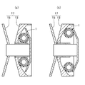
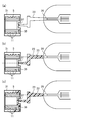
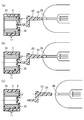
- 2A and 2B are cross-sectional views showing a pulley having the weight roller shown in FIG. 3 (a) to 3 (c) are diagrams showing a method of manufacturing the weight roller shown in FIG. 4 (a) to 4 (c) are diagrams showing a method of manufacturing the weight roller shown in FIG. 5 (a) to 5 (c) are diagrams showing a method of manufacturing the weight roller shown in FIG. 6 (a) to 6 (c) are diagrams showing a method of manufacturing the weight roller shown in FIG.
- FIG. 1 is a cross-sectional view showing a weight roller according to an embodiment of the present invention.
- 2A and 2B are cross-sectional views showing a pulley having the weight roller shown in FIG.
- the weight roller 1 includes a cylindrical weight adjusting member 5, and a collar 3 made of resin that covers the outer peripheral surface and the bottom surface of the weight adjusting member 5.
- At least one of the outer circumferential surface and the bottom surface of the weight adjusting member 5 is formed with a meshing portion 11 for improving the meshing with the collar 3 and reducing noise during use.
- the meshing portion 11 is at least one of a groove, a concave portion, and a convex portion.
- a plurality of grooves are formed on the outer peripheral surface, top surface, and bottom surface of the weight adjusting member 5 as the meshing portion 11.
- the meshing part 11 may be a concave part or a convex part that is discontinuous in the circumferential direction.
- the meshing part 11 meshes with the inner peripheral surface of the collar 3, rattling during use can be prevented. Further, the meshing portion 11 may be formed on the bottom surface or the top surface of the weight adjusting member 5. In this case, when the weight roller 1 rolls, the rattling between the weight adjusting member 5 and the collar 3 is effectively prevented. Can be suppressed. Although the meshing portion 11 can be effectively suppressed when formed on the outer peripheral surface of the weight adjusting member 5 and when formed on the bottom surface, the direction of rattling is different. Is formed on both the outer peripheral surface and the bottom surface of the weight adjusting member 5, it is possible to effectively suppress rattling in any direction, and as a result, it is possible to more strongly suppress rattling. . Furthermore, if the meshing part 11 is formed on the upper surface of the weight adjusting member 5, the rattling can be more effectively suppressed.
- the height of the convex portion or the depth of the concave portion formed on the bottom surface of the weight adjusting member 5 is 0.3 mm or less because manufacturing becomes easy. According to this configuration, it is possible to prevent the flow behavior from being inhibited or changed when the resin passes through the convex portion or the concave portion in the molding process of the collar 3. For this reason, it becomes possible to mold the collar 3 under the same conditions as in the case where the convex portion or the concave portion is not formed on the bottom surface, and as a result, the collar 3 can be easily manufactured.
- the collar 3 has, for example, a bottomed cylindrical shape in which an opening is provided only in the upper part, and a concave gate dropping part 7 is provided in the bottom part.
- the gate drop portion 7 is formed with traces of pin gates used during molding.
- the weight adjusting member 5 is composed of a metal and a resin that functions as a binder.
- the metal constituting the weight adjusting member 5 include stainless steel (SUS), titanium, tungsten, and the like.
- the resin contained in the weight adjusting member 5 include polyamide (PA) 6, PA66, PA46, polyphenylene sulfide (PPS), and the like.
- examples of the resin constituting the color 3 include PA6, PA66, PA46, and PPS.
- the resin constituting the collar 3 and the resin contained in the weight adjusting member 5 may be different from each other, but may be the same resin. When both are the same resin, since the resin in the weight adjusting member 5 is melt-bonded when the collar 3 is molded, the bonding force between the collar 3 and the weight adjusting member 5 can be improved.
- a concave gate portion 9 is provided on the bottom surface of the weight adjusting member 5.
- a convex pin gate mark is formed on the gate portion 9. Since the gate portion 9 is engaged with the collar 3, the effect of preventing rattling is further improved.
- the weight roller 1 of this embodiment is used for a pulley of a continuously variable transmission.
- the pulley 17 of the continuously variable transmission has a substantially disc-like appearance, and includes a guide plate 15 fixed to the rotating shaft, and a rotating shaft direction.
- a movable plate 13 is provided. The gap between the guide plate 15 and the movable plate 13 becomes smaller toward the radially outer side of the pulley 17.
- the plurality of weight rollers 1 are arranged so that the outer peripheral surfaces thereof are in contact with the guide plate 15 and the movable plate 13.
- the weight adjustment member 5 is less likely to come out than a weight roller that fits the weight adjustment member into the collar. It has become. Further, since it is not necessary to precisely process the edge of the weight adjusting member 5 as compared with the type of weight roller in which the weight adjusting member is fitted into the collar, it is possible to reduce the manufacturing man-hour and reduce the manufacturing cost.
- the weight of the weight roller 1 can be adjusted without changing the overall shape of the weight roller 1.
- FIGS. 4 (a) to 4 (c) are diagrams showing a process of forming the weight adjusting member 5 in the method of manufacturing the weight roller shown in FIG. 5 (a) to 5 (c) and FIGS. 6 (a) to 6 (c) are diagrams showing a process of forming the collar 3 in the method of manufacturing the weight roller shown in FIG.
- the weight adjusting member 5 is formed by injection molding using a molding machine.
- a resin material 19 containing a metal powder or a low melting point metal material is injected from a nozzle 26 of a molding machine into a mold cavity 21 through a runner 23 and a pin gate 35.
- the mold for the weight adjusting member is formed with at least one of a groove, a concave portion and a convex portion.
- the metal powder for example, stainless steel (SUS), titanium, tungsten or the like can be used.
- the low melting point metal material for example, a magnesium alloy, an aluminum alloy, or the like can be used.
- the low melting point metal material is not limited to powder and can be used even in a pellet form.
- the resin for example, PA6, PA66, PA46, PPS or the like can be used.
- the amount of metal powder or low melting point metal material added to the resin is, for example, about 20 to 50% by weight.
- the resin material 19 is filled in the cavity 21, the resin material 19 is solidified by, for example, holding at 100 ° C. for 1 minute. Thereafter, by opening the mold, the runner 23 is automatically excised (FIG. 4C). A concave gate portion is formed on the bottom surface of the weight adjusting member 5 formed in this way.
- the collar 3 is molded by injection molding using a molding machine.
- the same resin 33 as the resin for the weight adjusting member 5 is injected from the nozzle 26 of the molding machine into the mold cavity 31 through the runner 23 and the pin gate 37. After filling the resin 33 into the cavity 31, for example, the resin 33 is solidified by holding at 100 ° C. for 0.3 minutes. Thereafter, the runner 23 is automatically cut off by opening the mold (FIG. 6C).
- the collar 3 molded in this manner has a bottomed cylindrical shape, and a concave gate dropping portion is formed at the bottom.
- a pin gate (accurately, a gate mark) 37 is formed in the gate dropping portion.
- the collar 3 covers the outer peripheral surface and the bottom surface of the weight adjusting member 5, and the inner peripheral surface of the collar 3 is in close contact with the meshing portion 11 of the weight adjusting member 5.
- the collar 3 is formed so as to wrap the weight adjusting member 5
- the weight adjusting member 5 is more easily removed than a conventional weight roller in which a separately prepared weight adjusting member is fitted into the collar. Can be prevented.
- the collar 3 is produced by molding, it is not necessary to cut the weight adjusting member 5 to increase the edge accuracy. Furthermore, since the step of press-fitting the weight adjusting member 5 into the collar 3 is not required, it is possible to manufacture the weight roller with a small number of man-hours.
- the runner portion can be removed at the time of mold opening without performing the gate cutting process. For this reason, it becomes possible to reduce a manufacturing man-hour and to reduce manufacturing cost.
- the engagement portion 11 having a complicated shape can be formed by injection molding the weight adjusting member 5, it is possible to effectively prevent rattling during operation.
- the weight adjustment member 5 can also be shape
- the weight roller according to an example of the present invention can be applied to a continuously variable transmission such as a two-wheeled vehicle.
Landscapes
- Engineering & Computer Science (AREA)
- Manufacturing & Machinery (AREA)
- Mechanical Engineering (AREA)
- Transmissions By Endless Flexible Members (AREA)
- Injection Moulding Of Plastics Or The Like (AREA)
- Moulds For Moulding Plastics Or The Like (AREA)
Abstract
ウエイトローラー1は、円筒状の重量調整部材5と、重量調整部材5の外周面及び底面を覆い、樹脂からなるカラー3とを備え、重量調整部材5の外周面には溝、凹部及び凸部のうち少なくとも1つが形成されている。
Description
本明細書に開示された技術は、ウエイトローラー及びその製造方法に関する。
自動二輪車等には、エンジンの回転数の変化に応じて変速が自動的に行われる無段変速装置が用いられている。この無段変速装置は、回転軸に固定された固定プレートと回転軸方向に移動可能な可動プレートとで構成されたプーリと、このプーリに巻き掛けられた伝動ベルトと、可動プレートの背面側に位置し、回転軸に固定されたガイドプレートと、可動プレートとガイドプレートとの隙間に配置された円筒状のウエイトローラーとを備えている。可動プレートとガイドプレートとの隙間は、プーリの径方向外側に向かうに従って小さくなる。
特許文献1には、円筒状の重量調整部材と、芯材の外表面を覆う樹脂層とを備えたウエイトローラーが記載されている。特許文献2には、重量調整部材と、重量調整部材の外表面を覆う樹脂層とを備えたウエイトローラーが記載され、樹脂層を成形することも記載されている。
また、特許文献3には、繊維強化樹脂を用いたウエイトローラーが記載されている。特許文献4には、重量調整部材が樹脂層から抜脱しにくいウエイトローラが記載されている。特許文献5には、センタゲート方式にて有底円筒形状に成形される樹脂層を備えたウエイトローラーが記載されている。
しかしながら、従来のウエイトローラーでは、重量調整部材が樹脂層から抜ける場合がある。また、重量調整部材の切削加工を行う必要があり、ウエイトローラーの製造コストが高くなる場合がある。
本発明の目的は、安価に製造でき、重量調整部材の抜けが生じにくいウエイトローラーを提供することにある。
本発明の一実施形態に係るウエイトローラーは、円筒状の重量調整部材と、重量調整部材の外周面及び底面を覆い、樹脂からなるカラーとを備え、重量調整部材の外周面には溝、凹部及び凸部のうち少なくとも1つが形成されている。
本発明の別の実施形態に係るウエイトローラーの製造方法は、金型のキャビティ内に金属粉末又は低融点金属材と樹脂とを注入して射出成形により円筒状の重量調整部材を成形する工程と、射出成形により樹脂からなる有底円筒形状のカラーを形成する工程とを備え、前記重量調整部材の外周面には溝、凹部及び凸部のうち少なくとも1つが形成されており、前記カラーは、前記重量調整部材の外周面及び底面を覆う。
本発明の一実施形態に係るウエイトローラー及びその製造方法によれば、比較的安価で重量調整部材の抜けが生じにくいウエイトローラーを実現することが可能となる。
(実施形態)
図1は、本発明の一実施形態に係るウエイトローラーを示す断面図である。図2(a)、(b)は、図1に示すウエイトローラーを有するプーリを示す断面図である。
図1は、本発明の一実施形態に係るウエイトローラーを示す断面図である。図2(a)、(b)は、図1に示すウエイトローラーを有するプーリを示す断面図である。
図1に示すように、本実施形態に係るウエイトローラー1は、円筒状の重量調整部材5と、重量調整部材5の外周面及び底面を覆い、樹脂からなるカラー3とを備えている。
重量調整部材5の外周面及び底面の少なくとも一方には、カラー3との噛み合わせを向上させ、使用時の異音を低減するための噛み合わせ部11が形成されている。
ここで、噛み合わせ部11は、溝、凹部及び凸部のうち少なくとも1つである。図1に示す例では、噛み合わせ部11として複数の溝が重量調整部材5の外周面、上面及び底面に形成されている。噛み合わせ部11としては、溝の他に、周方向に不連続な凹部や凸部などであってもよい。カラー3の内周面には、重量調整部材5の噛み合わせ部11と係合する形状の凸部(突条を含む)及び凹部のうち少なくとも1つが形成されている。
この噛み合わせ部11がカラー3の内周面と噛み合っていることにより、使用時のがたつきが防止できる。また、噛み合わせ部11は重量調整部材5の底面又は上面に形成されていてもよく、この場合、ウエイトローラー1が転がる場合に重量調整部材5とカラー3との間のがたつきを効果的に抑制することができる。噛み合わせ部11が重量調整部材5の外周面に形成される場合と底面に形成される場合とで効果的に抑えることができるがたつきの方向が異なるので、噛み合わせ部(すなわち凹部等)11が重量調整部材5の外周面と底面の両方に形成されていれば、いずれの方向のがたつきも効果的に抑えることができ、結果としてより強固にがたつきを抑えることが可能となる。さらに、噛み合わせ部11が重量調整部材5の上面に形成されていれば、がたつきをより効果的に抑えることができる。
重量調整部材5の底面に形成される凸部の高さ又は凹部の深さが0.3mm以下であれば製造が容易になるので好ましい。この構成によれば、カラー3の成形工程において、樹脂が当該凸部又は凹部を通過する際にその流動挙動が阻害されたり又は変化するのを防ぐことができる。このため、底面に凸部又は凹部を形成しない場合と同様の条件でカラ-3の成形をすることが可能になり、結果としてカラー3の製造が容易になる。
カラー3は例えば上方のみに開口が設けられた有底円筒形状であり、底部に凹状のゲート落とし込み部7が設けられている。ゲート落とし込み部7には、成形時に用いられたピンゲートの跡が形成されている。
なお、重量調整部材5の外周面に凸部(突条含む)が形成され、カラー3の内周面に形成された凹部がこの凸部と係合する場合には、重量調整部材5とカラー3との間のがたつきを防止できる上、さらなる重量増が可能となる。
重量調整部材5は、金属と、バインダとして働く樹脂とで構成されている。重量調整部材5を構成する金属としては、例えばステンレス鋼材(SUS)、チタン、タングステン等が挙げられる。重量調整部材5に含まれる樹脂としては、例えばポリアミド(PA)6、PA66、PA46、ポリフェニレンスルファイド(PPS)等が挙げられる。
一方、カラー3を構成する樹脂としては、例えばPA6、PA66、PA46、PPS等が挙げられる。カラー3を構成する樹脂と重量調整部材5に含まれる樹脂とは互いに異なる樹脂であってもよいが、同じ樹脂であってもよい。両者が同一の樹脂である場合、カラー3の成形時に重量調整部材5中の樹脂と溶融結合するので、カラー3と重量調整部材5との結合力を向上させることができる。
重量調整部材5の底面には、凹状のゲート部9が設けられている。このゲート部9には、凸状のピンゲート跡が形成されている。このゲート部9がカラー3と係合していることにより、がたつきの防止効果がさらに向上している。
本実施形態のウエイトローラー1は、無段変速機のプーリに用いられる。
図2(a)、(b)に示すように、無段変速機のプーリ17は、略円板状の外観を有しており、回転軸に固定されたガイドプレート15と、回転軸方向に移動可能な可動プレート13とを備えている。ガイドプレート15と可動プレート13との隙間は、プーリ17の径方向外側に向かうに従って小さくなる。プーリ17において、複数のウエイトローラー1は、その外周面がガイドプレート15及び可動プレート13に接するように配置されている。
プーリ17を備えた無段変速機において、エンジンの回転数が増加するとウエイトローラー1に作用する遠心力が大きくなり、ウエイトローラー1がプーリ17の径方向外方に移動する(図2(b)参照)。この移動に伴って可動プレート13の内側面がウエイトローラー1に押され、可動プレート13の外側面がガイドプレート15のプーリフェイスに近づく。その結果、プーリ17の溝幅が狭くなる。すると、伝動ベルト(図示せず)とプーリ17との噛み合い半径が大きくなり、無段階に変速が行われる。
本実施形態のウエイトローラー1では、カラー3が重量調整部材5の外周面及び底面を覆っているので、重量調整部材をカラーに嵌め込むタイプのウエイトローラーに比べて重量調整部材5の抜けが発生しにくくなっている。また、重量調整部材をカラーに嵌め込むタイプのウエイトローラーに比べて重量調整部材5のエッジを精密に加工する必要がなくなるので、製造工数を削減して製造コストを下げることが可能となる。
さらに、重量調整部材5とカラ-3とは比重が異なるので、重量調整部材5の外周面又は底面に溝、凹部及び凸部の少なくとも1つを形成し、カラー3に凸部及び凹部の一方を形成することで、ウエイトローラー1全体の形状を変えずにウエイトローラー1の重量を調整することが可能となる。
-製造方法-
図3(a)~(c)、図4(a)~(c)、は、図1に示すウエイトローラーの製造方法において重量調整部材5を成形する工程を示す図である。図5(a)~(c)、図6(a)~(c)は、図1に示すウエイトローラーの製造方法においてカラー3を成形する工程を示す図である。
図3(a)~(c)、図4(a)~(c)、は、図1に示すウエイトローラーの製造方法において重量調整部材5を成形する工程を示す図である。図5(a)~(c)、図6(a)~(c)は、図1に示すウエイトローラーの製造方法においてカラー3を成形する工程を示す図である。
まず、図3(a)~(c)、図4(a)~(c)に示すように、成形機を用いた射出成形により重量調整部材5を成形する。
具体的には、金属粉末又は低融点金属材料を含む樹脂材料19を成形機のノズル26から金型のキャビティ21内にランナー23及びピンゲート35を介して注入する。重量調整部材用の金型には、溝、凹部及び凸部のうち少なくとも1つが形成されている。
金属粉末としては、例えばステンレス鋼材(SUS)、チタン、タングステン等を使用することができる。低融点金属材料としては、例えばマグネシウム合金、アルミニウム合金等を使用することができる。低融点金属材料については、粉末に限らずペレット状等であっても用いることができる。
樹脂としては、例えばPA6、PA66、PA46、PPS等を使用することができる。金属粉末又は低融点金属材料の樹脂に対する添加量は、例えば20~50重量%程度である。
樹脂材料19をキャビティ21内に充填した後、例えば100℃で1分間保持することで樹脂材料19を固化させる。その後、金型を開くことにより、ランナー23は自動的に切除される(図4(c))。このようにして成形された重量調整部材5の底面には凹状のゲート部が形成されている。
次いで、図5(a)~(c)、図6(a)~(c)に示すように、成形機を用いた射出成形によりカラー3を成形する。
具体的には、重量調整部材5用の樹脂と同じ樹脂33を成形機のノズル26から金型のキャビティ31内にランナー23及びピンゲート37を介して注入する。樹脂33をキャビティ31内に充填した後、例えば100℃で0.3分間保持することで樹脂33を固化させる。その後、金型を開くことにより、ランナー23は自動的に切除される(図6(c))。このようにして成形されたカラー3は有底円筒形状であり、底部に凹状のゲート落とし込み部が形成されている。ゲート落とし込み部には、ピンゲート(正確にはゲート跡)37が形成される。カラー3は重量調整部材5の外周面及び底面を覆い、カラー3の内周面は重量調整部材5の噛み合わせ部11と密着している。
本実施形態の製造方法によれば、カラー3が重量調整部材5を包み込むように形成されるので、別途作製した重量調整部材をカラーに嵌め込む従来のウエイトローラーに比べて重量調整部材5の脱落を防ぐことができる。
また、本実施形態の製造方法によれば、カラー3を成形により作製しているので、重量調整部材5を切削加工してエッジ精度を上げる必要がなくなる。さらに、重量調整部材5をカラー3に圧入する工程が不要となるので、少ない工数でウエイトローラーを製造することが可能となる。
本実施形態の製造方法では、ピンゲート方式を採用しているので、ゲートカット工程を行わなくても、型開きの際にランナー部分を除去することができる。このため、加工工数を少なくして製造コストを低減することが可能となる。
また、重量調整部材5を射出成形することにより、複雑な形状の噛み合わせ部11を形成することができるので、動作時のがたつきを効果的に防止することができる。
なお、本実施形態では重量調整部材5を成形した後にカラー3の成形を行う例を示したが、カラー3を成形した後に重量調整部材5を成形することもできる。
本実施形態では、ウエイトローラー1及びその製造方法の一例を説明したが、各部材の形状、構成、配置、構成材料、サイズ、製造条件、手順の前後等は本発明の趣旨を逸脱しない範囲において適宜変更可能である。
以上説明したように、本発明の一例に係るウエイトローラーは、二輪車等の無段変速機等に適用されうる。
1 ウエイトローラー
3 カラー
5 重量調整部材
7 ゲート落とし込み部
9 ゲート部
11 噛み合わせ部
13 可動プレート
15 ガイドプレート
17 プーリ
19 樹脂材料
21、31 キャビティ
23 ランナー
26 ノズル
33 樹脂
35、37 ピンゲート
3 カラー
5 重量調整部材
7 ゲート落とし込み部
9 ゲート部
11 噛み合わせ部
13 可動プレート
15 ガイドプレート
17 プーリ
19 樹脂材料
21、31 キャビティ
23 ランナー
26 ノズル
33 樹脂
35、37 ピンゲート
Claims (11)
- 円筒状の重量調整部材と、
前記重量調整部材の外周面及び底面を覆い、樹脂からなるカラーとを備え、
前記重量調整部材の外周面には溝、凹部及び凸部のうち少なくとも1つが形成されているウエイトローラー。 - 請求項1に記載のウエイトローラーにおいて、
前記カラーは有底円筒形状であり、
前記重量調整部材の底面及び上面の少なくとも一方にも溝、凹部及び凸部のうち少なくとも1つが形成されているウエイトローラー。 - 請求項1に記載のウエイトローラーにおいて、
前記カラーは有底円筒形状であり、底部に凹状のゲート落とし込み部が設けられていることを特徴とするウエイトローラー。 - 請求項1~3のうちいずれか1つに記載のウエイトローラーにおいて、
前記重量調整部材は金属及び樹脂で構成されていることを特徴とするウエイトローラー。 - 請求項1~4のうちいずれか1つに記載のウエイトローラーにおいて、
前記カラーを構成する樹脂と前記重量調整部材に含まれる樹脂とは同一であることを特徴とするウエイトローラー。 - 請求項1~5のうちいずれか1つに記載のウエイトローラーにおいて、
前記重量調整部材の底面には、凹状のゲート部が設けられ、前記カラーの内周面には前記ゲート部に係合する凸部が形成されていることを特徴とするウエイトローラー。 - 請求項1~6のうちいずれか1つに記載のウエイトローラーにおいて、
前記カラーの内周面には、前記重量調整部材の外周面に形成された溝、凹部及び凸部の少なくとも1つに係合する凸部又は凹部が形成されていることを特徴とするウエイトローラー。 - 金型のキャビティ内に金属粉末又は低融点金属材と樹脂とを注入して射出成形により円筒状の重量調整部材を成形する工程と、
射出成形により樹脂からなる有底円筒形状のカラーを形成する工程とを備え、
前記重量調整部材の外周面には溝、凹部及び凸部のうち少なくとも1つが形成されており、
前記カラーは、前記重量調整部材の外周面及び底面を覆うウエイトローラーの製造方法。 - 請求項8に記載のウエイトローラーの製造方法において、
前記カラーの底部には凹状のゲート落とし込み部が設けられていることを特徴とするウエイトローラーの製造方法。 - 請求項8又は9に記載のウエイトローラーの製造方法において、
前記重量調整部材は金属及び樹脂で構成されており、
前記カラーを構成する樹脂と前記重量調整部材に含まれる樹脂とは同一であることを特徴とするウエイトローラーの製造方法。 - 請求項8~10のうちいずれか1つに記載のウエイトローラーの製造方法において、
重量調整部材を成形する工程では、ピンゲートを介して成形材料を注入することを特徴とするウエイトローラーの製造方法。
Priority Applications (1)
| Application Number | Priority Date | Filing Date | Title |
|---|---|---|---|
| JP2015545539A JP5877286B1 (ja) | 2014-06-02 | 2015-04-09 | ウエイトローラー及びその製造方法 |
Applications Claiming Priority (2)
| Application Number | Priority Date | Filing Date | Title |
|---|---|---|---|
| JP2014-113827 | 2014-06-02 | ||
| JP2014113827 | 2014-06-02 |
Publications (1)
| Publication Number | Publication Date |
|---|---|
| WO2015186287A1 true WO2015186287A1 (ja) | 2015-12-10 |
Family
ID=54766374
Family Applications (1)
| Application Number | Title | Priority Date | Filing Date |
|---|---|---|---|
| PCT/JP2015/001996 Ceased WO2015186287A1 (ja) | 2014-06-02 | 2015-04-09 | ウエイトローラー及びその製造方法 |
Country Status (3)
| Country | Link |
|---|---|
| JP (1) | JP5877286B1 (ja) |
| TW (1) | TW201600771A (ja) |
| WO (1) | WO2015186287A1 (ja) |
Cited By (1)
| Publication number | Priority date | Publication date | Assignee | Title |
|---|---|---|---|---|
| EP3730812A4 (en) * | 2018-02-07 | 2020-12-16 | Bando Chemical Industries, Ltd. | ROLLER-WEIGHT, ITS MANUFACTURING PROCESS, AND MOLD FOR USE IN THE MANUFACTURE OF A ROLLER-WEIGHT |
Citations (5)
| Publication number | Priority date | Publication date | Assignee | Title |
|---|---|---|---|---|
| JPS6435161A (en) * | 1987-07-31 | 1989-02-06 | Yamaha Motor Co Ltd | Weight for automatic transmission with v-belt |
| JP2000055154A (ja) * | 1998-08-07 | 2000-02-22 | Bando Chem Ind Ltd | ウエイトローラ及びその製造方法 |
| JP2001234992A (ja) * | 2000-02-21 | 2001-08-31 | Honda Motor Co Ltd | ベルト変速機用ウエイトローラー |
| JP2006177468A (ja) * | 2004-12-24 | 2006-07-06 | Kakuichi Kasei Kk | ウェイトローラー |
| JP2013170598A (ja) * | 2012-02-17 | 2013-09-02 | Oiles Corp | Vベルト式自動変速機 |
-
2015
- 2015-04-09 JP JP2015545539A patent/JP5877286B1/ja not_active Expired - Fee Related
- 2015-04-09 WO PCT/JP2015/001996 patent/WO2015186287A1/ja not_active Ceased
- 2015-05-27 TW TW104116954A patent/TW201600771A/zh unknown
Patent Citations (5)
| Publication number | Priority date | Publication date | Assignee | Title |
|---|---|---|---|---|
| JPS6435161A (en) * | 1987-07-31 | 1989-02-06 | Yamaha Motor Co Ltd | Weight for automatic transmission with v-belt |
| JP2000055154A (ja) * | 1998-08-07 | 2000-02-22 | Bando Chem Ind Ltd | ウエイトローラ及びその製造方法 |
| JP2001234992A (ja) * | 2000-02-21 | 2001-08-31 | Honda Motor Co Ltd | ベルト変速機用ウエイトローラー |
| JP2006177468A (ja) * | 2004-12-24 | 2006-07-06 | Kakuichi Kasei Kk | ウェイトローラー |
| JP2013170598A (ja) * | 2012-02-17 | 2013-09-02 | Oiles Corp | Vベルト式自動変速機 |
Cited By (1)
| Publication number | Priority date | Publication date | Assignee | Title |
|---|---|---|---|---|
| EP3730812A4 (en) * | 2018-02-07 | 2020-12-16 | Bando Chemical Industries, Ltd. | ROLLER-WEIGHT, ITS MANUFACTURING PROCESS, AND MOLD FOR USE IN THE MANUFACTURE OF A ROLLER-WEIGHT |
Also Published As
| Publication number | Publication date |
|---|---|
| TW201600771A (zh) | 2016-01-01 |
| JPWO2015186287A1 (ja) | 2017-04-20 |
| JP5877286B1 (ja) | 2016-03-02 |
Similar Documents
| Publication | Publication Date | Title |
|---|---|---|
| JP6463867B1 (ja) | 回転型動力伝達部材の製造方法 | |
| US10738870B2 (en) | Two-color molding method and two-color molded body | |
| JP4173047B2 (ja) | 射出成形樹脂ギヤ,射出成形樹脂スプロケット,射出成形樹脂プーリ,射出成形樹脂ローラ、及び、射出成形樹脂ギヤ,射出成形樹脂スプロケット,射出成形樹脂プーリ,射出成形樹脂ローラの製造方法 | |
| JP6953321B2 (ja) | 偏心揺動型減速装置及び内歯歯車の製造方法 | |
| KR101495623B1 (ko) | 사출성형에 의한 수지 성형 기어의 제조방법 | |
| EP3238906B1 (en) | Manufacturing method of insert molded article | |
| JP5877286B1 (ja) | ウエイトローラー及びその製造方法 | |
| JP2008221687A (ja) | 樹脂製ヘリカル歯車の成形金型及びこの成形金型を用いて成形された樹脂製ヘリカル歯車 | |
| JP2008290402A (ja) | 合成樹脂製プーリの製造方法及び射出成形用金型 | |
| JP5517345B2 (ja) | 樹脂成形品の製造方法 | |
| JP5541052B2 (ja) | 樹脂シート製造方法 | |
| ITBO20060561A1 (it) | Motoriduttore e metodo per la sua realizzazione. | |
| CN111601986B (zh) | 配重辊、其制造方法以及用于制造配重辊的模具 | |
| KR102360895B1 (ko) | 스피닝 릴의 드라이브 기어용 다이캐스팅 금형 | |
| JP2016029288A (ja) | ウエイトローラー及びその製造方法 | |
| JP2008265016A (ja) | 樹脂成形方法及び射出成形装置 | |
| JP6131624B2 (ja) | 転がり軸受用合成樹脂製保持器の製造方法 | |
| JP2020143733A (ja) | 樹脂製歯車および歯車の多層成形方法 | |
| JP5483145B2 (ja) | プーリ及び樹脂プーリ付き転がり軸受 | |
| JP2022169462A (ja) | 圧縮射出成形による歯車の製造方法 | |
| JP2016068652A (ja) | 電動式パワーステアリング装置用のウォームホイールおよびその製造方法 | |
| CN107701691B (zh) | 塑料齿轮 | |
| US20090266455A1 (en) | Mold and process for manufacturing toothed sprockets for locking winding rollers of safety belts | |
| JP2000000852A (ja) | プラスチック成形品 | |
| JP5556365B2 (ja) | 樹脂製プーリの射出成形装置及び射出成形方法 |
Legal Events
| Date | Code | Title | Description |
|---|---|---|---|
| ENP | Entry into the national phase |
Ref document number: 2015545539 Country of ref document: JP Kind code of ref document: A |
|
| 121 | Ep: the epo has been informed by wipo that ep was designated in this application |
Ref document number: 15803585 Country of ref document: EP Kind code of ref document: A1 |
|
| NENP | Non-entry into the national phase |
Ref country code: DE |
|
| 122 | Ep: pct application non-entry in european phase |
Ref document number: 15803585 Country of ref document: EP Kind code of ref document: A1 |