WO2015182575A1 - 太陽電池モジュール用の端子ボックス、太陽電池モジュール及び太陽電池アレイ - Google Patents
太陽電池モジュール用の端子ボックス、太陽電池モジュール及び太陽電池アレイ Download PDFInfo
- Publication number
- WO2015182575A1 WO2015182575A1 PCT/JP2015/065007 JP2015065007W WO2015182575A1 WO 2015182575 A1 WO2015182575 A1 WO 2015182575A1 JP 2015065007 W JP2015065007 W JP 2015065007W WO 2015182575 A1 WO2015182575 A1 WO 2015182575A1
- Authority
- WO
- WIPO (PCT)
- Prior art keywords
- terminal box
- solar cell
- cable
- terminal
- cell module
- Prior art date
- Legal status (The legal status is an assumption and is not a legal conclusion. Google has not performed a legal analysis and makes no representation as to the accuracy of the status listed.)
- Ceased
Links
Images









Classifications
-
- H—ELECTRICITY
- H02—GENERATION; CONVERSION OR DISTRIBUTION OF ELECTRIC POWER
- H02S—GENERATION OF ELECTRIC POWER BY CONVERSION OF INFRARED RADIATION, VISIBLE LIGHT OR ULTRAVIOLET LIGHT, e.g. USING PHOTOVOLTAIC [PV] MODULES
- H02S40/00—Components or accessories in combination with PV modules, not provided for in groups H02S10/00 - H02S30/00
- H02S40/30—Electrical components
- H02S40/34—Electrical components comprising specially adapted electrical connection means to be structurally associated with the PV module, e.g. junction boxes
-
- Y—GENERAL TAGGING OF NEW TECHNOLOGICAL DEVELOPMENTS; GENERAL TAGGING OF CROSS-SECTIONAL TECHNOLOGIES SPANNING OVER SEVERAL SECTIONS OF THE IPC; TECHNICAL SUBJECTS COVERED BY FORMER USPC CROSS-REFERENCE ART COLLECTIONS [XRACs] AND DIGESTS
- Y02—TECHNOLOGIES OR APPLICATIONS FOR MITIGATION OR ADAPTATION AGAINST CLIMATE CHANGE
- Y02E—REDUCTION OF GREENHOUSE GAS [GHG] EMISSIONS, RELATED TO ENERGY GENERATION, TRANSMISSION OR DISTRIBUTION
- Y02E10/00—Energy generation through renewable energy sources
- Y02E10/50—Photovoltaic [PV] energy
Definitions
- the present invention relates to a terminal box for a solar cell module, a solar cell module, and a solar cell array.
- the solar cell module is formed, for example, by sealing a plurality of crystalline solar cells made of single crystal silicon or polycrystalline silicon pasted on a substrate such as glass with a sealing material such as a resin material or a protective film.
- Crystal solar cell modules and thin film solar cell modules formed by sealing thin film solar cells made of thin film photoelectric conversion layers formed on a substrate such as glass with a sealing material such as a resin material or a protective film.
- a sealing material such as a resin material or a protective film
- the lead wire electrically connected to the solar battery cell is usually pulled out to the outside, and the drawn lead wire is put into a terminal box connected to the cable. It is designed to be electrically connected.
- a terminal box may be provided on the back surface of the solar cell module body or on the side surface of the solar cell module body.
- a plurality of solar cell module bodies are connected in series via a terminal box, a plurality of solar cell module bodies are connected in parallel, or in series.
- the connected solar cell module body rows are connected in parallel to obtain a desired output voltage and generated power.
- the solar cell module when the terminal box is provided on the side surface of the solar cell module body, the solar cell module is used on the ceiling or wall of a building for lighting, as well as a sunroof for a passenger car, a building window, etc. It is particularly desirable in the case of a light transmission type (so-called see-through type) thin film solar cell module that can be used in a wide range of applications.
- a light transmission type so-called see-through type
- see-through lines a large number of elongated grooves (so-called see-through lines) are formed in the power generation unit to transmit light.
- a battery module can be mentioned.
- Patent Documents 2 and 3 disclose a terminal box for a solar cell module in which one cable is connected to one end and the other cable is connected to the other end opposite to the one end. is doing.
- a terminal box can be made, for example, about the size of the width of the cable.
- a cable having a single (one-core) electric wire may be connected to the terminal box body.
- FIG. 24 is a schematic configuration diagram schematically showing an example of a connection form of a plurality of solar cell modules Ma to Ma.
- FIG. 24 shows an example in which a plurality of terminal boxes Ba to Ba are provided on the side surfaces M1 of the plurality of solar cell module bodies M to M.
- a plurality of solar cell module bodies M to M are single (one core). Are connected in series via one cable Ca1 having a single electric wire Wa and the other cable Ca2 having a single (one-core) electric wire Wb.
- the lead wires L1 and L2 are taken out from the plurality of solar cell module bodies M to M, and the taken out lead wires L1 and L2 are connected to the positive side and the negative side of the terminal boxes Ba to Ba, respectively.
- the negative electrode side is connected to a single one electric wire Wa (negative electrode electric wire) in one cable Ca1
- the positive electrode side is a single other electric wire Wb (positive electrode electric wire) in the other cable Ca2.
- one single electric wire Wa (negative electrode electric wire) in one cable Ca1 and the other single electric wire Wb (positive electrode electric wire) in the other cable Ca2 are connected to each other via a connector CNa.
- each of the one cable and the other cable has a single (one-core) electric wire, and is suitable for parallel connection of solar cell modules.
- the terminal box configuration has not been fully studied.
- an object of the present invention is to provide a terminal box for a solar cell module, a solar cell module, and a solar cell array that can realize a reduction in size of a terminal box suitable for parallel connection of solar cell modules.
- the present invention provides a terminal box, a solar cell module, and a solar cell array for the following solar cell module.
- Terminal box for solar cell module A terminal box for a solar cell module according to the present invention is positive or negative at the terminal box body, one end of the terminal box body, and the other end opposite to the one end. A pair of electric wires is provided.
- the solar cell module according to the present invention includes a solar cell module main body and a terminal box, and the terminal box is opposite to the terminal box main body, one end of the terminal box main body, and the one end.
- the other end of the side is provided with a pair of positive and negative electric wires.
- the solar cell array according to the present invention includes a plurality of solar cell modules according to the present invention, and the positive / negative pair of other solar cell modules adjacent to the positive / negative pair of electric wires of one solar cell module.
- the plurality of solar cell modules are connected in parallel by being electrically connected to the electric wire.
- a mode in which a first terminal member provided in the terminal box main body and a second terminal member having a different polarity from the first terminal member have a laminated structure can be exemplified.
- a mode in which a diode is further provided in the terminal box body can be exemplified.
- connection position of one lead wire connecting portion electrically connected to one of the pair of lead wires taken out from the solar cell module body of the solar cell module and the pair of lead wires The aspect comprised so that the connection position of the other lead wire connection part electrically connected to the other lead wire of them may align in a predetermined direction can be illustrated.
- the solar cell module surrounds at least a part of a peripheral portion of a lead wire connecting portion electrically connected to at least one of the pair of lead wires taken out from the main body of the solar cell module.
- the aspect by which the protrusion part which protruded in is provided can be illustrated.
- one cable is connected to one end of the terminal box body, and the other cable is connected to the other end opposite to the one end.
- the said other cable can illustrate the aspect provided with the said pair of positive / negative electric wires, respectively.
- the one cable and the other cable can be exemplified as a two-core integrated cable in which the pair of positive and negative wires are integrated.
- the two-core integrated cable is branched into one-core cables on the side opposite to the side connected to the terminal box body, and at the ends of the two one-core cables on the branch side,
- a pair of connectors is provided can be exemplified.
- FIG. 1 is a conceptual diagram showing an example of a connection form of a plurality of solar cell modules provided with a terminal box for a solar cell module according to an embodiment of the present invention.
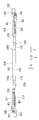
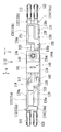
- FIG. 2 is a front view showing a schematic configuration showing an example of a terminal box according to the embodiment of the present invention.
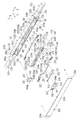
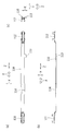
- FIG. 3 is an exploded perspective view showing a schematic configuration of a terminal box body portion in the terminal box shown in FIG. 4 is a schematic configuration diagram of a terminal box main body portion in the terminal box shown in FIG. 2, wherein (a) is a front view thereof, (b) is a first side view thereof, and (c) ) Is a second side view thereof.
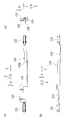
- 5 is a schematic configuration diagram of a box lid in the terminal box main body shown in FIG.
- FIG. 2 is a front view thereof, (b) is a first side view thereof, and (c). Is a second side view thereof.
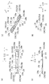
- 6 is a schematic cross-sectional view of a terminal box main body portion in the terminal box shown in FIG. 2, wherein (a) is a cross-sectional view taken along line AA shown in FIG.
- FIG. 4 is a cross-sectional view taken along the line BB shown in FIG. 4A, and
- FIG. 4C is a cross-sectional view taken along the line CC shown in FIG.
- FIG. 7 is a front view showing a schematic configuration of constituent members such as a first terminal member and a second terminal member removed from the terminal box body shown in FIG. 4.
- FIG. 8 is a perspective view showing a schematic configuration of constituent members such as a first terminal member and a second terminal member removed from the terminal box body shown in FIG.
- FIG. 9 is a schematic configuration of a first terminal member provided in the terminal box body, wherein (a) is a front view thereof, (b) is a first side view thereof, and (c) is a front view thereof. It is the 2nd side view.
- FIG. 10 is a schematic configuration of a second terminal member provided in the terminal box body, wherein (a) is a front view thereof, (b) is a first side view thereof, and (c) is a front view thereof. It is the 2nd side view.
- FIG. 9 is a schematic configuration of a first terminal member provided in the terminal box body, wherein (a) is a front view thereof, (b) is a first side view thereof, and (c) is a front view thereof. It is the 2nd side view.
- FIG. 10 is a schematic configuration of a second terminal member provided in the terminal
- FIG. 11 is a schematic configuration diagram of a spacer provided in the terminal box body, in which (a) is a front view thereof, (b) is a first side view thereof, and (c) is a diagram thereof. It is a perspective view, (d) is the 2nd side view.
- FIG. 12 is a schematic configuration diagram of a third terminal member provided in the terminal box body, wherein (a) is a front view thereof, (b) is a first side view thereof, and (c). Is a second side view thereof.
- FIG. 13 is a schematic configuration diagram of a fixing member provided in the terminal box body, in which (a) is a front view thereof, (b) is a first side view thereof, and (c) is a front view thereof.
- FIG. 14 is a schematic configuration diagram showing a branch portion portion of one cable and the other cable which are two-core integrated cables in the terminal box shown in FIG. 2, and (a) is a left side view thereof.
- (B) is a front view thereof, and (c) is a right side view thereof.
- FIG. 15 is a schematic configuration diagram showing a branched portion portion of one cable and the other cable which are two-core integrated cables in the terminal box shown in FIG. 2, and (a) is a first side view thereof.
- FIG. 14B is a cross-sectional view taken along the line AA shown in FIG. 16A and 16B are perspective views of the branch portion shown in FIGS. 14 and 15, wherein FIG.
- FIG. 16A is a perspective view of the branch portion viewed from the front side
- FIG. 16B is a rear view of the branch portion. It is the perspective view seen from the side.
- FIG. 17 is a perspective view showing the internal structure by removing the cover lid of the cover member.
- FIG. 18 is a schematic configuration diagram illustrating another example of the terminal box according to the embodiment of the present invention, in which (a) is a front view thereof and (b) is a first side view thereof. (C) is a rear view thereof.
- FIG. 19 is a schematic configuration diagram of a terminal box main body portion in the terminal box shown in FIG. 18, wherein (a) is a front view thereof, (b) is a first side view thereof, and (c) ) Is a second side view thereof.
- FIG. 18 is a schematic configuration diagram illustrating another example of the terminal box according to the embodiment of the present invention, in which (a) is a front view thereof and (b) is a first side view thereof. (C) is a
- FIG. 20 is a schematic configuration diagram of a box lid in the terminal box body shown in FIG. 18, wherein (a) is a front view thereof and (b) is a first side view thereof.
- FIG. 21 is a schematic cross-sectional view of a terminal box main body portion in the terminal box shown in FIG. 18, wherein (a) is a cross-sectional view taken along line AA shown in FIG.
- FIG. 19 is a sectional view taken along line BB shown in FIG. 19A
- FIG. 19C is a sectional view taken along line CC shown in FIG. 19A
- FIG. FIG. 20A is a cross-sectional view taken along the line DD shown in FIG. 19A
- FIG. 19E is a cross-sectional view taken along the line EE shown in FIG. FIG.
- FIG. 22 is a schematic configuration diagram showing a branched portion portion of one cable and the other cable that are two-core integrated cables in the terminal box shown in FIG. 18, and (a) is a front view thereof. (B) is the 1st side view, (c) is the back view, (d) is the right side view.
- FIG. 23 is a schematic configuration diagram showing a branch portion portion of one cable and the other cable which are two-core integrated cables in the terminal box shown in FIG. 18, and FIG. FIG. 22B is a cross-sectional view taken along the line AA shown in FIG. 22B, FIG. 22B is a cross-sectional view taken along the line BB shown in FIG. 22A, and FIG. FIG. 22D is a sectional view taken along the line CC, and FIG. 22D is a sectional view taken along the line DD shown in FIG.
- FIG. 24 is a schematic configuration diagram schematically illustrating an example of a connection form of a plurality of solar cell modules.
- FIG. 1 is a conceptual diagram showing an example of a connection form of a plurality of solar cell modules MO to MO provided with a terminal box 100 for a solar cell module according to an embodiment of the present invention.
- FIG. 1 shows an example in which terminal boxes 100 to 100 are provided on side surfaces M1 of a plurality of solar cell module bodies M to M.
- a solar cell array 400 is composed of a plurality of solar cell modules MO to MO.
- Each of the solar cell modules MO to MO includes a solar cell module body M and a terminal box 100.
- the solar cell array 400 includes a plurality of solar cell modules MO, and among the solar cell modules MO to MO, another solar cell module MO in which a pair of positive and negative electric wires W1, W2 of one solar cell module MO is adjacent.
- a plurality of solar cell modules MO to MO are connected in parallel by being electrically connected to the pair of positive and negative electric wires W1, W2.
- the pair of positive and negative electric wires is simply referred to as “a pair of electric wires”.
- the terminal boxes 100 to 100 are configured such that a plurality of solar cell module bodies M to M can be connected in parallel.
- the plurality of solar cell modules MO to MO are connected in parallel via one cable 210 having a pair (two-core) of wires W1 and W2 and the other cable 220 having a pair (two-core) of wires W1 and W2.
- the lead wires L1 and L2 are taken out from the plurality of solar cell module bodies M to M, and the lead wire L1 on the positive electrode side of the lead wires L1 and L2 taken out is the diode 140 (in this example, a block king diode).
- the lead wire L2 on the negative electrode side is connected to the negative electrode side of the terminal boxes 100 to 100.
- the positive electrode side and the negative electrode side are respectively connected to a pair of electric wires (one electric wire W1 (positive electric wire in this example) and the other electric wire W2 (negative electric wire in this example)) in one cable 210.
- the other cable 220 is connected to a pair of electric wires (one electric wire W1 (positive electric wire in this example) and the other electric wire W2 (negative electric wire in this example)).
- a pair of wires in one cable 210 (one wire W1 (positive wire in this example) and the other wire W2 (in this example, negative wire)) and a pair of wires in the other cable 220 (one wire W1 ( In this example, the positive electric wire) and the other electric wire W2 (in this example, the negative electric wire) are connected to each other via the connector pair 300,300.
- the plurality of solar cell modules MO to MO have the same configuration.
- the terminal box 100 according to the present embodiment can configure a solar cell module power cable 200 by connecting a plurality of solar cell module bodies M to M to each other.
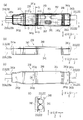
- FIG. 2 is a front view showing a schematic configuration showing an example of the terminal box 100 according to the embodiment of the present invention.
- FIG. 3 is an exploded perspective view showing a schematic configuration of the terminal box body 101 portion in the terminal box 100 shown in FIG.
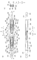
- FIG. 4 is a schematic configuration diagram of a terminal box body 101 portion in the terminal box 100 shown in FIG. 4 (a) is a front view thereof, FIG. 4 (b) is a first side view thereof, and FIG. 4 (c) is a second side view thereof.
- FIG. 4 shows a state of the terminal box body 101 with the box lid 102 removed.
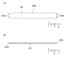
- FIG. 5 is a schematic configuration diagram of the box lid 102 in the terminal box body 101 shown in FIG.
- FIG. 5 (a) is a front view thereof
- FIG. 5 (b) is a first side view thereof
- FIG. 5 (c) is a second side view thereof.
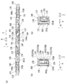
- FIG. 6 is a schematic cross-sectional view of the terminal box body 101 portion in the terminal box 100 shown in FIG. 6A is a cross-sectional view taken along the line AA shown in FIG. 4A, and FIG. 6B is a cross-sectional view taken along the line BB shown in FIG. 4A.
- FIG. 6C is a cross-sectional view taken along the line CC shown in FIG. FIG. 6 shows a state in which the box lid 102 is provided.
- FIG. 7 and 8 are a front view and a perspective view, respectively, showing a schematic configuration of components such as the first terminal member 110 and the second terminal member 120 removed from the terminal box body 101 shown in FIG.
- FIG. 9 is a schematic configuration of the first terminal member 110 provided in the terminal box body 101.
- FIG. 9A is a front view thereof
- FIG. 9B is a first side view thereof
- FIG. 9C is a second side view thereof.
- FIG. 10 is a schematic configuration of the second terminal member 120 provided in the terminal box body 101.
- 10 (a) is a front view thereof
- FIG. 10 (b) is a first side view thereof
- FIG. 10 (c) is a second side view thereof.
- FIG. 11 is a schematic configuration diagram of the spacer 130 provided in the terminal box main body 101.
- 11 (a) is a front view thereof
- FIG. 11 (b) is a first side view thereof
- FIG. 11 (c) is a perspective view thereof
- FIG. 11 (d) is a perspective view thereof.
- FIG. 12 is a schematic configuration diagram of the third terminal member 150 provided in the terminal box body 101.
- FIG. 12A is a front view thereof
- FIG. 12B is a first side view thereof
- FIG. 12C is a second side view thereof.
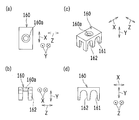
- FIG. 13 is a schematic configuration diagram of a fixing member 160 provided in the terminal box main body 101.
- 13 (a) is a front view thereof
- FIG. 13 (b) is a first side view thereof
- FIG. 13 (c) is a perspective view thereof
- FIG. 13 (d) is a perspective view thereof. It is a 2nd side view.
- a terminal box 100 for a solar cell module includes a terminal box main body 101 and one end portion 100a of the terminal box main body 101 (FIGS. 2, 3, 4A, 4B, and FIG. 6 (a)) and the other end 100b opposite to the one end 100a (see FIGS. 2, 3, 4 (a), 4 (b) and 6 (a)), respectively.
- a pair of electric wires (W1, W2), (W1, W2) (refer to FIG. 2, FIG. 3, FIG. 4 (a) and FIG. 4 (c)) are provided.
- the terminal box 100 includes one cable 210 and the other cable 220 (see FIGS. 2 to 4 and 6A) and a terminal box body 101 (see FIGS. 2 to 4 and 6). I have.
- Both the one cable 210 and the other cable 220 include a pair of electric wires W1 and W2.
- a cable pair in which two one-core cables are independent from each other, or a two-core integrated cable in which a pair (two-core) electric wires are integrated can be used as the one cable 210 and the other cable 220.
- one cable 210 and the other cable 220 are two-core integrated cables in which a pair of (two-core) electric wires are integrated.
- One cable 210 and the other cable 220 have a pair of electric wires W1 and W2 having the same configuration, and the size in the first direction X and the size in the second direction Y are the same or substantially the same. .
- the terminal box main body 101 has one cable insertion portion 101a (see FIGS. 4A and 6A) through which one cable 210 is inserted, and the other cable insertion portion 101b through which the other cable 220 is inserted (see FIG. 3 and FIG. 4 (a) and FIG. 6 (a)).
- the terminal box 100 is configured such that one cable 210 is connected to one end portion 100a of the terminal box body 101 and the other cable 220 is connected to the other end portion 100b.
- One cable insertion portion 101a in the terminal box main body 101 is configured to insert one cable 210 from one end portion 100a.
- the other cable insertion portion 101b in the terminal box main body 101 is configured to insert the other cable 220 from the other end portion 100b.
- one cable insertion portion 101a and the other cable insertion portion 101b are both insertion holes, and the center of one cable insertion portion 101a and the center of the other cable insertion portion 101b are in the insertion direction Z. Are lined up on a virtual straight line.
- the terminal box 100 includes a first terminal member 110 (see FIGS. 3, 4A, 6, 7, 8, and 9) and a second terminal member 120 having a polarity different from that of the first terminal member 110. (See FIGS. 3, 4A, 6, 7, 8, and 10).
- the first terminal member 110 and the second terminal member 120 are provided in the terminal box main body 101.
- the first terminal member 110 and the second terminal member 120 have a laminated structure.
- the first terminal member 110 is provided in the terminal box main body 101 and is electrically connected to one electric wire W1 of the pair of electric wires W1 and W2 of the one cable 210 inserted through the terminal box main body 101.
- One terminal 111 (see FIGS. 3, 4A, 7, 8, 9A and 9B) connected to the terminal box 101 and the other cable inserted into the terminal box body 101 It has the other terminal 112 (refer FIG.3, FIG.4 (a), FIG.7, FIG.8 and FIG.9) electrically connected to one electric wire W1 of a pair of 220 electric wires W1, W2. .
- the second terminal member 120 is provided in the terminal box main body 101 and is electrically connected to the other electric wire W2 of the pair of electric wires W1, W2 of the one cable 210 inserted through the terminal box main body 101.
- One terminal 121 see FIGS. 3, 4A, 7, 8, 10A, and 10B
- the other terminal 122 (refer to FIG. 3, FIG. 4 (a), FIG. 7, FIG. 8, and FIG. 10) that is electrically connected to the other of the wires W ⁇ b> 1 and W ⁇ b> 2.
- first terminal member 110 one terminal 111 is electrically connected to one electric wire W ⁇ b> 1 of one cable 210 inserted from one end portion 100 a of the terminal box main body 101, and the other terminal 112 is connected to the terminal box main body 101. It is electrically connected to one electric wire W1 of the other cable 220 inserted from the other end 100b.
- second terminal member 120 one terminal 121 is electrically connected to the other electric wire W ⁇ b> 2 of one cable 210 inserted from one end 100 a of the terminal box body 101, and the other terminal 122 is connected to the terminal box body 101. It is electrically connected to the other electric wire W2 of the other cable 220 inserted from the other end 100b.
- the first terminal member 110 and the second terminal member 120 are both made of a metal material.
- the first terminal member 110 and the second terminal member 120 are plate-shaped.
- the terminal box body 101 is made of a resin material.
- the terminal box 100 includes a direction in which the pair of electric wires W1 and W2 on one side and the pair of electric wires W1 and W2 on the other side are provided (in this example, the insertion direction Z), and one of the pair of electric wires W1 and W2.
- a direction specifically orthogonal or substantially orthogonal to both the direction in which the electric wire W1 and the other electric wire W2 are juxtaposed (the first direction X in this example) (in the second direction Y in this example)
- the first terminal member 110 and the second terminal member 120 are laminated.
- the pair of wires W1 and W2 of one cable 210 and the pair of wires W1 and W2 of the other cable 220 both pass through the one cable 210 and the other cable 220.
- the first terminal member 110 and the second terminal member 120 are arranged in both the insertion direction Z and the first direction X.
- the first terminal member 110 and the second terminal member 120 intersect in the insertion direction Z (in this example, orthogonal or substantially orthogonal). They are stacked in the second direction Y that intersects (in this example, orthogonal or substantially orthogonal).
- one cable 210 is inserted into the terminal box body 101 so that an imaginary straight line connecting the axes of the pair of electric wires W1 and W2 is parallel or substantially parallel to the first direction X, and the other cable 220 is inserted. Is inserted into the terminal box body 101 so that an imaginary straight line connecting the axes of the pair of electric wires W1, W2 is parallel or substantially parallel to the first direction X.
- predetermined plane portions that are parallel or substantially parallel to both the first direction X and the insertion direction Z are stacked in the second direction Y.
- the insertion direction Z is the longitudinal direction of the one cable 210 and the other cable 220 (in this example, the longitudinal direction of the terminal box body 101), and more specifically, the center of the one cable insertion portion 101a and the other cable.
- the direction is a straight line connecting the center of the insertion part 101b.
- the terminal box body 101 has a hexahedral box shape that is open in one direction (in this example, one side in the second direction Y).
- the terminal box body 101 includes a box lid 102 (see FIGS. 2, 3, 5, and 6) that closes the open side of the terminal box body 101.
- the box lid 102 is engaged with the terminal box main body 101 in an uneven manner.
- a plurality of engaging protrusions 102a to 102a that engage with the terminal box body 101 are provided on the outer peripheral portion of the box lid 102.
- the plurality of engaging convex portions 102a to 102a are provided at two locations on both sides of the box lid 102 in the insertion direction Z and at one location on one side of the box lid 102 in the first direction X.
- a plurality of engagement recesses 101c to 101c (see FIGS. 3 and 4A) that engage with the plurality of engagement projections 102a to 102a, respectively, are provided on the inner peripheral portion on the open side of the terminal box body 101.
- the box lid 102 is fitted on the open side of the terminal box main body 101, and the plurality of engaging convex portions 102a to 102a are engaged with the plurality of engaging concave portions 101c to 101c in the terminal box main body 101, respectively.
- the open side of the main body 101 is closed.
- the box lid 102 is made of a resin material.
- the terminal box body 101 has a long shape in the insertion direction Z.
- the terminal box body 101 has one outer surface (installation surface 101d) (see FIGS. 3, 4, and 6) in the first direction X fixed to the side surface M1 (see FIG. 1) of the solar cell module body M. It has become.
- the size d1 (see FIG. 3) of the terminal box body 101 in the second direction Y is equal to or less than the thickness of the solar cell module body M (in this example, about the thickness of the solar cell module body M).
- the second direction Y is the thickness direction of the solar cell module body M.
- the first terminal member 110 and the second terminal member 120 extend in the insertion direction Z and are provided in the terminal box main body along the insertion direction Z.
- the one terminal 111 and the other terminal 112 in the first terminal member 110 are provided on a virtual straight line along the insertion direction Z.
- the one terminal 121 and the other terminal 122 in the second terminal member 120 are provided on an imaginary straight line along the insertion direction Z.
- the connection position of one terminal 111 in the first terminal member 110 and the connection position of one terminal 121 in the second terminal member 120 are configured to be aligned or substantially aligned in the second direction Y (FIG. 8). reference).
- the connection position of the other terminal 112 in the first terminal member 110 and the connection position of the other terminal 122 in the second terminal member 120 are configured to be aligned or substantially aligned in the second direction Y (see FIG. 8).
- the outer ends in the insertion direction Z of one terminal 111 in the first terminal member 110 and one terminal 121 in the second terminal member 120 are configured to be aligned or substantially aligned in the insertion direction Z (see FIGS. 7 and 8). ).
- the outer terminals 112 in the insertion direction Z of the other terminals 112 in the first terminal member 110 and the other terminals 122 in the second terminal member 120 are configured to be aligned or substantially aligned in the insertion direction Z (see FIGS. 7 and 8).
- the first terminal member 110 and the second terminal member 120 have the same or substantially the same size in the insertion direction Z.
- the height of the terminal box body 101 (in this example, the size d2 in the first direction X (see FIG. 3)) is 20 mm or less (preferably 15 mm or less, more preferably 14 mm or less). .
- the size d1 in the second direction Y is smaller than the size d2 in the first direction X.
- the size d1 of the terminal box main body 101 in the second direction Y can exemplify 10 mm or less, and the size of the terminal box main body 101 in the insertion direction Z can exemplify 130 mm or less.
- the terminal box 100 is provided in the terminal box main body 101 and is a spacer 130 (FIGS. 3 and 4) that electrically insulates the first terminal member 110 and the second terminal member 120 from each other. (A), FIG.6, FIG.7, FIG.8 and FIG. 11) are further provided.
- the spacer 130 includes a holding portion that holds the first terminal member 110 and the second terminal member 120, and the holding portion also serves as an insulating portion.
- the spacer 130 has a central portion 130a in the first direction X from one outer side in the first direction X (see FIGS. 3, 6B, 7, 11A, and 11C).
- a first insertion guide groove 131 (in this example, first insertion guide grooves 131a and 131b on both sides in the insertion direction Z) (see FIGS. 3, 7, 8, and 11).
- a first restricting portion 132 (in this example, first restricting portions 132a and 132b on both sides in the insertion direction Z) for restricting the outward movement of the first terminal member 110 in the first direction X (FIGS. 3, 7 and 7). 8, 11 (a), 11 (c) and 11 (d)).
- the first insertion guide groove 131 is formed along the insertion direction Z, and both ends of the first direction X and the insertion direction Z are open. Accordingly, the spacer 130 is moved by the first insertion guide groove 131 (131a, 131b) and the first restricting portion 132 (132a, 132b) to both sides in the second direction Y and the first direction X. The movement of the terminal box 100 to both sides can be restricted, and the assembly workability of the terminal box 100 can be improved accordingly.
- the spacer 130 has a second insertion guide groove 133 (the other end in the insertion direction Z in this example) through which the second terminal member 120 is inserted from the other outer side in the first direction X toward the central portion 130a in the first direction X.
- a second insertion guide groove 133 (Second insertion guide groove on the side of the portion 100b) (see FIGS. 3, 7, 8, and 11) and a second restricting portion 134 that restricts the outward movement of the second terminal member 120 in the first direction X (see FIG. In this example, it has 2nd control part 134a, 134b (refer FIG.3, FIG.7, FIG.11) in the both sides of the insertion direction Z.
- 2nd control part 134a, 134b (refer FIG.3, FIG.7, FIG.11) in the both sides of the insertion direction Z.
- the second insertion guide groove 133 is formed along the insertion direction Z, and both ends of the first direction X and the insertion direction Z are open. Accordingly, the spacer 130 moves the second terminal member 120 to both sides in the second direction Y and moves to both sides in the first direction X by the second insertion guide groove 133 and the second restricting portion 134 (134a, 134b). As a result, the assembly workability of the terminal box 100 can be improved accordingly.
- the spacer 130 is made of a resin material having excellent insulating properties (for example, PPE resin: polyphenylene ether resin).
- the spacer 130 has a long shape in the insertion direction Z.
- the spacer 130 has a size d3 (see FIG. 11A) in the first direction X that is a predetermined length longer than the size between the inner walls in the first direction X of the terminal box body 101 so that the spacer 130 is surely fit in the terminal box body 101.
- the size in the insertion direction Z is set to a size that is (slightly) smaller than the size between the inner walls in the insertion direction Z of the terminal box body 101 by a predetermined length.
- the spacer 130 has a size (thickness) that is as thin as possible in the second direction Y, and the insulation and retention of the first terminal member 110 and the second terminal member 120 (and the third terminal member 150 described later). The size (thickness and shape) can be maintained.
- the spacer 130 has a positioning portion 135 (see FIGS. 3, 6B, 11A, and 11C) that is positioned with respect to the terminal box body 101 within the terminal box body 101. Is provided. Further, in the terminal box body 101, a positioning unit 135 that controls the movement of the spacer 130 in the first direction X and the insertion direction Z by the positioning unit 135 positions the positioning unit 135 (see FIGS. 3 and 6B). In the position. Thereby, the assembly workability
- the positioning part 135 (135a, 135b) is a pair of through-holes penetrating in the second direction Y on both sides of the spacer 130 in the first direction X.
- the restricting portion 103 (103a, 103b) is a protruding portion that protrudes inward in the second direction Y on both sides in the first direction X of the side surface of the terminal box body 101.
- the diameter of the restricting portion 103 (103a, 103b) is set to a size (slightly) smaller than the diameter of the positioning portion 135 (135a, 135b) to the extent that the positioning portion 135 can be smoothly inserted.
- the restricting portion 103 (103a, 103b) is integrally formed with the terminal box body 101.
- the first terminal member 110 is provided with a positioning portion 113 (see FIG. 3, FIG. 6A and FIG. 9) that is positioned with respect to the spacer 130. Thereby, the assembly workability
- the positioning portion 113 is a protruding portion that protrudes to one side in the first direction X, and is locked to a locking portion 130b (see FIG. 6A) of the spacer 130. . Thereby, the first terminal member 110 can restrict movement in the insertion direction Z by the positioning portion 113.
- the positioning portion 113 is integrally formed with the first terminal member 110.
- the one terminal 111 and the other terminal 112 in the first terminal member 110 are fixed by crimping one electric wire W1 in one cable 210 and one electric wire W1 in the other cable 220, respectively.
- one terminal 111 and another terminal 112, one electric wire W1, and one electric wire W1 are further fixed by solder.
- the second terminal member 120 is provided with a positioning portion 120a (see FIGS. 3 and 10A) that is positioned with respect to the spacer 130.
- the positioning portion 120a is a curved portion that is curved at 90 degrees or substantially 90 degrees between the first direction X and the insertion direction Z in the plate-like portion along both the first direction X and the insertion direction Z. It is latched by the latching
- FIG. Thereby, the 2nd terminal member 120 can control the movement in the insertion direction Z by the positioning part 120a.
- the one terminal 121 and the other terminal 122 in the second terminal member 120 are fixed by crimping the other electric wire W2 in one cable 210 and the other electric wire W2 in the other cable 220, respectively.
- the one terminal 121 and the other terminal 122, the other electric wire W2, and the other electric wire W2 are further fixed by solder.
- the terminal box 100 includes a diode 140 (blocking diode in this example) provided in the terminal box body 101 (see FIGS. 3, 4A, 6A, 7 and 8). ).
- the diode 140 includes a diode main body 141, two terminals 142 and 143, and a heat radiating portion 144.
- the diode body 141 is provided with two terminals 142 and 143 protruding in the same direction, and a heat radiating portion 144 is provided on the opposite side to the direction in which the two terminals 142 and 143 protrude.
- the two terminals 142 and 143 are directed to one side in the insertion direction Z (one end 100a side in this example), while the heat radiating portion 144 is the other side in the insertion direction Z (the other end 100b side in this example). It is provided in the terminal box main body 101 (in this example, the spacer 130) so as to face.
- the diode 140 has a protrusion 136 (see FIGS. 3 and 4) provided in the spacer 130 in a holding hole 144 a (see FIGS. 3, 6 (a) and 7) provided in the heat radiating portion 144.
- FIG. 6 (a), FIG. 7, FIG. 8 and FIG. 11) are penetrated and fixed by a fixing portion 136a (see FIG. 4 (a), FIG. 7 and FIG. 8).
- the protrusion 136 is integrally formed with the spacer 130.
- the terminal box body 101 has a pair of lead wire insertion holes 101e and 101f (FIGS. 3 and 4B) through which the pair of lead wires L1 and L2 taken out from the solar cell module body M (see FIG. 1) are respectively inserted. Reference) is provided.
- the pair of lead wire insertion holes 101e and 101f are sized by a predetermined value (slightly) larger than the cross-sectional shape of the lead wires L1 and L2 so that the lead wires L1 and L2 can be smoothly inserted.
- One of the first terminal member 110 and the second terminal member 120 (in this example, the first terminal member 110) is inserted into one of the pair of lead wire insertion holes 101e and 101f of the terminal box body 101. It is configured to be electrically connected via a diode 140 to one lead wire L1 of the pair of lead wires L1 and L2 inserted through the hole 101e.
- One of the first terminal member 110 and the second terminal member 120 is the other lead wire insertion of the pair of lead wire insertion holes 101e, 101f of the terminal box body 101. It is configured to be electrically connected to the other lead wire L2 of the pair of lead wires L1 and L2 inserted through the hole 101f.
- the terminal box 100 includes a third terminal member 150 (FIG. 3, FIG. 4 (a), FIG. 6 (a), FIG. 6 (c), FIG. 7, FIG. 8, and FIG. 12).
- the third terminal member 150 is made of a metal material.
- the third terminal member 150 is plate-shaped.
- the first terminal member 110, the second terminal member 120, and the third terminal member 150 are stacked in the second direction Y.
- the first terminal member 110, the second terminal member 120, and the third terminal member 150 are laminated in the second direction Y with predetermined plane portions that are parallel or substantially parallel to both the first direction X and the insertion direction Z. ing.
- the third terminal member 150 has one lead wire connecting portion 151 (FIG. 3, FIG. 4A) that is electrically connected to one lead wire L1 inserted through one lead wire insertion hole 101e of the terminal box body 101. ) In FIG. 6 (a), FIG. 6 (c), FIG. 7, FIG. 8 and FIG. 12) and one terminal 142 of the diode 140 (in this example, the anode side).
- One diode connection part 152 see FIGS. 3, 8, 12A and 12B).
- One of the first terminal member 110 and the second terminal member 120 (in this example, the first terminal member 110) is the other electrically connected to the other terminal 143 (in this example, the cathode side) of the diode 140.
- the diode connection portion 114 (see FIGS. 3, 4A, 7, 8, 9A, and 9B).
- One of the first terminal member 110 and the second terminal member 120 (the second terminal member 120 in this example) is connected to the other lead wire L2 inserted from the other lead wire insertion hole 101f of the terminal box body 101.
- the other lead wire connecting portion 123 (see the hatched portion in FIGS. 3 and 4A, FIGS. 6A, 7, 8, and 10) is electrically connected.
- one diode connecting portion 152 in the third terminal member 150 is a bent convex portion that is bent so as to protrude toward the one terminal 142 side of the diode 140.
- one diode connection part 152 and one terminal 142 of the diode 140 can be easily electrically connected by a connection member such as solder.
- one diode connection portion 152 is in the second direction in the first direction X at the same or substantially the same position as the one terminal 121 and the other terminal 122 in the second terminal member 120.
- Y it is located at the same or substantially the same position as the diode connection part 114 in the first terminal member 110, and further, at the same or substantially the same position in the insertion direction Z as the other diode connection part 114 in the first terminal member 110. positioned.
- the third terminal member 150 extends from one diode connection portion 152 toward the other end portion 100b in the insertion direction Z, bends so as to be displaced toward the open side of the terminal box body 101 in the second direction Y, and In the first direction X, one lead wire connecting portion 151 is formed by being displaced toward the first terminal member 110 side.
- the other diode connection portion 114 in the first terminal member 110 is a bent convex portion that is bent so as to protrude toward the other terminal 143 of the diode 140. Thereby, the other diode connection part 114 and the other terminal 143 of the diode 140 can be easily electrically connected by a connection member such as solder.
- the first terminal member 110 is bent at both ends in the insertion direction Z so as to be displaced toward one electric wire W1 (one cable 210) and one electric wire W1 (the other cable 220) in the second direction Y. Terminals 111 and other terminals 112 are formed. Thereby, the connection position in the 2nd direction Y with one terminal 111 and the other terminal 112, one electric wire W1 (one cable 210), and one electric wire W1 (the other cable 220) can be match
- connection form in which the two terminals 142 and 143 of the diode 140 are respectively connected to the one diode connection part 152 in the third terminal member 150 and the other diode connection part 114 in the first terminal member 110 is limited thereto.
- a connection form by soldering, a connection form by caulking, a connection form by ultrasonic waves, or a connection form combining at least two of these can be exemplified.
- the two terminals 142 and 143 of the diode 140 are connected to one diode connection portion 152 and the other diode connection portion 114 by solder.
- the terminal box 100 includes a connection position of one lead wire connecting portion 151 and a pair of leads electrically connected to one lead wire L1 of the pair of lead wires L1 and L2 taken out from the solar cell module body M.
- the connection position of the other lead wire connecting portion 123 that is electrically connected to the other lead wire L2 of the wires L1 and L2 is configured to be aligned or substantially aligned in a predetermined direction (second direction Y in this example). ing.
- connection position of the other lead wire connection portion 123 in the second terminal member 120 is the same or substantially the same position in the second direction Y as the connection position of the one lead wire connection portion 151 in the third terminal member 150. is doing. That is, one lead wire connection portion 151 and the other lead wire connection portion 123 are provided so that the connection positions in the second direction Y are aligned or substantially aligned.
- connection position of the other lead wire connection portion 123 in the second terminal member 120 is located at the same or substantially the same position in the first direction X as the connection position of the one lead wire connection portion 151 in the third terminal member 150. ing. That is, one lead wire connecting portion 151 and the other lead wire connecting portion 123 are provided so that the connection positions in the first direction X are aligned or substantially aligned. Specifically, the connection position of one lead wire connection portion 151 and the connection position of the other lead wire connection portion 123 are provided so as to be located on an imaginary straight line along the insertion direction Z.
- the pair of lead wire insertion holes 101e and 101f extend along the insertion direction Z, and are provided so that the insertion positions in the second direction Y are aligned or substantially aligned. Specifically, the pair of lead wire insertion holes 101e and 101f are provided so as to be positioned on a virtual straight line along the insertion direction Z. The pair of lead wire insertion holes 101e and 101f are connected to one lead wire of the terminal box body 101 to such an extent that the pair of lead wires L1 and L2 do not come into contact with one lead wire connecting portion 151 and the other lead wire connecting portion 123.
- the pair of lead wires L1 and L2 are inserted into the pair of lead wire insertion holes 101e and 101f as they are in a straight state, respectively, and connected to one lead wire connecting portion 151 and the other lead wire connecting portion 123, respectively. be able to.
- one of the first terminal member 110 and the second terminal member 120 (in this example, the second terminal member 120) one terminal 121 and the other terminal 122 are virtual straight lines along the insertion direction Z.
- a bent portion 124 (see FIGS. 3, 4 (b), 6 (b), 7, 8, and 10) formed by bending at 90 degrees or substantially 90 degrees in one direction is provided. .
- the second terminal member 120 is bent so as to be displaced from the other lead wire connection portion 123 toward the other electric wire W2 (one cable 210) side in the second direction Y on the one end portion 100a side in the insertion direction Z.
- One terminal 121 is formed.
- the second terminal member 120 is outside the two terminals 142 and 143 of the diode 140 in the second direction Y on the other end 100b side in the insertion direction Z from the other lead wire connection portion 123 (the open side of the terminal box body 101).
- To be displaced so as to be displaced to one inner wall of the terminal box body 101 in this example, the inner wall 101g on the installation surface 101d side) (FIGS.
- the second terminal member 120 is further bent at 90 degrees or substantially 90 degrees so as to surround the two terminals 142 and 143 of the diode 140 and the spacer 130 to form a bent portion 124.
- the second terminal member 120 has a bent portion 124 extending toward the other end portion 100b in the insertion direction Z, and a spacer 130 on the side opposite to the side bent at 90 ° or substantially 90 ° on the one end portion 100a side. It bends again by 90 degrees or substantially 90 degrees toward the side, and becomes parallel or substantially parallel to the other lead wire connecting portion 123.
- the second terminal member 120 further extends toward the other end portion 100b in the insertion direction Z and is bent so as to be displaced toward the other electric wire W2 (the other cable 220) in the second direction Y to form the other terminal 112. is doing. That is, the bent portion 124 is formed so as to avoid the diode 140 and the third terminal member 150. Further, the second terminal member 120 is bent at both ends in the insertion direction Z so as to be displaced toward the other electric wire W2 (one cable 210) and the other electric wire W2 (the other cable 220) in the second direction Y.
- the connection position in Y can be matched.
- a portion corresponding to the bent portion 124 of the inner wall of the terminal box body 101 has a recess or a through hole (in this example, a through hole 101h (FIG. 3). 4 (b) and 6 (b))
- the bent portion 124 is a recess or a through-hole (this hole in the inner wall of the terminal box body 101 (in this example, the inner wall 101g of the installation surface 101d).
- wiring is performed in a state of entering the through hole 101h)
- the bent portion 124 does not protrude outward from the terminal box main body 101.
- the recessed portion or the through hole has a shape corresponding to the bent portion 124.
- the shape of the bent portion 124 is such that the bent portion 124 can smoothly enter. There is a size only (slightly) larger size.
- each of these members is formed by a plurality of members.
- the electrical resistance tends to increase at the contact portions between them and the area where the area of each member is reduced, and it becomes difficult to allow a relatively large current.
- the first terminal member 110, the second terminal member 120, and the third terminal member 150 are formed by integrally forming a metal plate by cutting and bending, respectively.
- the thickness of the 1st terminal member 110, the 2nd terminal member 120, and the 3rd terminal member 150 is made the same or substantially the same.
- the spacer 130 electrically insulates between the first terminal member 110 and the second terminal member 120, and between the first terminal member 110 and the third terminal member 150 and the second terminal member 120.
- the third terminal member 150 is electrically insulated from the third terminal member 150.
- the spacer 130 has a pair of mounting portions 138 and 139 (FIGS. 3, 4A, and 6A) on which one lead wire connecting portion 151 and the other lead wire connecting portion 123 are respectively mounted. 7, 8 and 11).
- one placement portion 138 on which one lead wire connection portion 151 is placed is the other terminal 112 and the second terminal member 120 of the first terminal member 110 in the insertion direction Z.
- the other mounting portion 139 that is provided between the other terminal 122 and the diode 140 and on which the other lead wire connecting portion 123 is mounted is connected to one terminal 111 of the first terminal member 110 in the insertion direction Z and It is provided between one terminal 121 of the second terminal member 120 and the diode 140.
- the terminal box body 101 is electrically connected to at least one of the pair of lead wires L1 and L2 (L1 and / or L2) taken out from the solar cell module body M.
- Protruding portions (138a and / or 139a) are provided to protrude so as to surround at least a part of the peripheral edge portion of the lead wire connecting portion (151 and / or 123).
- one protruding portion 138a protruding from the thickness of one lead wire connecting portion 151 so as to surround at least a part of the peripheral edge portion of one lead wire connecting portion 151 (FIGS. 3A and 3B). 4 (a), FIG. 7, FIG. 8 and FIG. 11) and the other protrusion protruding from the thickness of the other lead wire connecting portion 123 so as to surround at least a part of the peripheral edge portion of the other lead wire connecting portion 123.
- a portion 139a is provided.
- one protrusion 138 a and the other protrusion 139 a are provided on the spacer 130.
- the one projecting portion 138a is provided in a straight line along the outer peripheral portion of the one lead wire connecting portion 151 placed on the one placing portion 138 at the peripheral portion of the one placing portion 138.
- the other protruding portion 139a is provided in a straight line along the outer peripheral portion of the other lead wire connecting portion 123 mounted on the other mounting portion 139 at the periphery of the other mounting portion 139.
- One protrusion 138 a and the other protrusion 139 a are integrally formed with the spacer 130.
- the pair of electric wires W1, W2 of one cable 210 and the pair of electric wires W1, W2 of the other cable 220 are both arranged in the first direction X, and the first terminal member 110 and the first Although the two terminal members 120 (and the third terminal member 150) are stacked in the second direction Y, the present invention is not limited to this.
- the terminal box 100 is provided in the terminal box body 101, and the insertion portion of one cable 210 (a pair of electric wires W1 and W2 in this example) and the insertion portion of the other cable 220 (this In the example, a pair of fixing members 160 and 160 (see FIGS. 3, 4A, 6A, and 13) for fixing the pair of electric wires W1 and W2) to the terminal box body 101 are further provided. .
- the pair of fixing members 160 and 160 are a pair of press contact portions 161 and 162 (FIGS. 3 and 13B to 13D) that press contact the pair of electric wires W1 and W2 to the terminal box body 101, respectively. ))).
- the fixing member 160 is made of a resin material.
- the one end portion 100a of the terminal box body 101 is provided with restriction portions 101i and 101i for restricting movement of the one fixing member 160 toward the other end portion 100b in the insertion direction Z (FIGS. 3 and 4A). )) Is provided.
- the one fixing member 160 has a size in the insertion direction Z such that the one fixing member 160 can be surely accommodated in the terminal box main body 101, and between the restriction portions 101i, 101i and the inner wall on the one end 100a side in the insertion direction Z of the terminal box main body 101. The size is smaller than the distance by a predetermined length (slightly).
- the terminal box main body 101 restricts the movement of both sides in the insertion direction Z of the one fixing member 160 between the restriction portions 101i, 101i and the inner wall on the one end portion 100a side in the insertion direction Z of the terminal box main body 101. be able to.
- the one fixing member 160 has a size in the first direction X so that it can be surely accommodated in the terminal box body 101 by a predetermined length than the distance between both inner walls in the first direction X of the terminal box body 101. (Slightly) small size.
- the terminal box body 101 can restrict the movement of one fixing member 160 on both sides in the first direction X between the inner walls in the first direction X of the terminal box body 101.
- the other end portion 100b of the terminal box body 101 has restriction portions 101j and 101j for restricting movement of the other fixing member 160 toward the one end portion 100a in the insertion direction Z (see FIGS. 3 and 4A). Is provided.
- the other fixing member 160 has a size in the insertion direction Z such that the other fixing member 160 fits securely in the terminal box body 101 and the inner wall on the other end 100b side in the insertion direction Z of the terminal box body 101. The size is (slightly) smaller than the distance between them by a predetermined length.
- the terminal box main body 101 restricts the movement of both sides in the insertion direction Z of the other fixing member 160 between the restriction portions 101j, 101j and the inner wall on the other end 100b side in the insertion direction Z of the terminal box main body 101. can do.
- the one fixing member 160 has a size in the first direction X so that it can be surely accommodated in the terminal box body 101 by a predetermined length than the distance between both inner walls in the first direction X of the terminal box body 101. (Slightly) small size. Thereby, the terminal box body 101 can restrict the movement of the other fixing member 160 on both sides in the first direction X between the inner walls in the first direction X of the terminal box body 101.
- the pair of pressure contact portions 161 and 162 have an inverted U-shaped concave shape that covers the pair of electric wires W1 and W2 from the open side of the terminal box body 101 in the second direction Y.
- the pair of press contact portions 161 and 162 gradually decreases in size in the first direction X from the concave-shaped open end toward the side opposite to the open end.
- the pair of fixing members 160 and 160 cover the pair of electric wires W1 and W2 so as to cover the pair of press contact portions 161 and 162, respectively, and press the pair of fixing members 160 and 160 toward the pair of electric wires W1 and W2 in the second direction Y.
- the pair of press contact portions 161 and 162 can be securely fixed to the terminal box body 101 while the pair of electric wires W1 and W2 are sandwiched.
- the pair of fixing members 160, 160 are provided with through holes 160a, 160a (see FIGS. 3, 4A and 13A to 13C) penetrating in the second direction Y. ing.
- the one end portion 100a and the other end portion 100b of the terminal box body 101 are provided with projecting portions 101k and 101k (see FIGS. 3 and 4A) projecting toward the open side in the second direction Y.
- the pair of fixing members 160, 160 are inserted through the projecting portions 101k, 101k in the one end portion 100a and the other end portion 100b of the terminal box main body 101 through the through holes 160a, 160a, and by a predetermined fixing means (in this example, an adhesive). Fixed.
- the pair of fixing members 160, 160 sandwiching the pair of electric wires W1, W2 can be fixed to the terminal box body 101.
- the terminal box body 101 is provided with air vent holes (in this example, lead wire insertion holes 101e and 101f and through holes 101h) through which air in the terminal box body 101 is released when the filler is introduced.
- air vent holes in this example, lead wire insertion holes 101e and 101f and through holes 101h
- each above-mentioned structural member is assembled
- the main body 101 is filled with a filler, and a box lid 102 is attached to the terminal box main body 101.
- the terminal box 100 is provided adjacent to the terminal box main body 101 and seal members 170 and 170 (FIGS. 2, 3, 4, and 4) that seal one cable 210 and the other cable 220. 6 (a)).
- seal members 170 and 170 FGS. 2, 3, 4, and 4
- strength of the vicinity of the terminal box main body 101 in the one cable 210 and the other cable 220 can be improved.
- the sealing member 170 for example, a shrinkable tube provided with an adhesive (so-called shrinkable tube with adhesive) can be used.
- one cable 210 and the other cable 220 are both two-core integrated cables as described above, but in this embodiment, the side connected to the terminal box body 101 Is bifurcated so that the opposite side is divided into one-core cables, and at the ends of the two one-core cables (211, 212), (221, 222) (see FIG. 2) on the branch side, Connector pairs 300, 300 (see FIG. 2) are provided.
- the connector pair 300 includes one connector 301 (a male connector in this example) and the other connector 302 (a female connector in this example).
- One one-core cable 211, 221 in one cable 210 and the other cable 220 includes one electric wire W1.
- the other one-core cables 212 and 222 in the one cable 210 and the other cable 220 include the other electric wire W2.
- the pair of connectors 301 and 302 provided on one cable 210 and the pair of connectors 302 and 301 provided on the other cable 220 are configured to be connectable.
- the terminal box 100 is configured to connect one one-core cable 211 in one cable 210 and one one-core cable 221 in the other cable 220, and the other one-core cable in the one cable 210.
- 212 and the other one-core cable 222 of the other cable 220 are connected to each other, and one one-core cable 211 of the one cable 210 is connected to one connector 301 of the pair of connectors 301, 302.
- the other one-core cable 212 of the one cable 210 is provided with the other connector 302 of the pair of connectors 301 and 302.
- One one-core cable 221 in the other cable 220 is provided with the other connector 302 of the pair of connectors 301, 302, and the other one-core cable 222 in the other cable 220 has a pair of connectors One of the connectors 301 and 302 is provided.
- One connector 301 and the other connector 302 in one cable 210 have different connector shapes, and one connector 301 and the other connector 302 in the other cable 220 have different connector shapes.
- the pair of connectors 301 and 302 in one cable 210 and the pair of connectors 301 and 302 in the other cable 220 are of the same type.
- the length of one one-core cable 211 and the other one-core cable 212 of one cable 210 that is a two-core integrated cable are different. Further, the length of one divided one-core cable 221 and the other one-core cable 222 of the other cable 220 that is a two-core integrated cable is different.
- the shorter one-core cable 211 of the one cable 210 and the longer one-core cable 221 of the other cable 220 can be connected, and the longer one of the one cable 210 is connected.
- the one-core cable 212 and the shorter one-core cable 222 of the other cable 220 can be connected.
- the shorter one-core cable 211 of one cable 210 and the longer one-core cable 221 of the other cable 220 are connected, the shorter one-core cable 211 and the longer one-core cable 221 And the longer one-core cable 212 of one cable 210 and the shorter one-core cable 222 of the other cable 220 are connected to each other.
- the total length with the core cable 222 is equal or substantially equal.
- the length of the shorter one-core cable 211 of one cable 210 and the shorter one-core cable 222 of the other cable 220 are equal or substantially equal, and the one cable 210
- the longer one-core cable 212 of the other cable 220 and the longer one-core cable 221 of the other cable 220 are equal or substantially equal.
- the shape of the connector 302 is the same as that of the connector 302 provided on the longer one-core cable 212 of the one cable 210 and the connector 302 provided on the longer one-core cable 221 of the other cable 220.
- the connector shape is the same shape.
- the color arrangement of the one one-core cable 211 and the other one-core cable 212 which are divided into one cable 210 which is a two-core integrated cable is different.
- One color of the one-core cable 221 and the other one-core cable 222 of the other cable 220 that is a two-core integrated cable are different in color scheme.
- one one-core cable 211 of one cable 210 and one one-core cable 221 of the other cable 220 have the same color
- the other one-core cable 212 of the one cable 210 and the other cable 220 are the same.
- the other one-core cable 222 has the same color.
- FIG. 14 and FIG. 15 are schematic configuration diagrams showing a branching portion 230 portion in one cable 210 and the other cable 220 which are two-core integrated cables in the terminal box 100 shown in FIG.
- FIG. 14A is a left side view thereof
- FIG. 14B is a front view thereof
- FIG. 14C is a right side view thereof.
- FIG. 15A is a first side view thereof
- FIG. 15B is a cross-sectional view taken along the line AA shown in FIG. 14B.
- FIG. 16 is a perspective view of the branching portion 230 shown in FIGS. 14 and 15.
- FIG. 16A is a perspective view of the branching portion 230 viewed from the front side
- FIG. 16B is a perspective view of the branching portion 230 viewed from the rear side.
- FIG. 17 is a perspective view showing the internal structure by removing the cover lid 242 of the cover member 240. 14 to 17, one cable 210 and the other cable 220 are shown in one drawing.
- the terminal box 100 is provided on the branch portion 230 of the one cable 210 and the other cable 220 that are two-core integrated cables, and covers the entire branch portion 230.
- the branch portion 230 is a base portion where one one-core cables 211 and 221 and the other one-core cables 212 and 222 are branched with respect to the two-core integrated cables 210a and 220a.
- the cover member 240 of one cable 210 passes through the two-core integrated cable 210a of one cable 210 at one end, and one one-core cable 211 at the other end opposite to the one end.
- the other one-core cable 212 is inserted.
- the cover member 240 of the other cable 220 is inserted through the two-core integrated cable 220a of the other cable 220 into one end, and the one-core cable 221 and the other end at the other end opposite to the one end.
- the single-core cable 222 is inserted.
- the cover member 240 includes a cover main body 241.
- the cover main body 241 has a first insertion portion 241a through which the two-core integrated cables 210a and 220a are inserted from one end, and one one-core cables 211 and 221 and the other one-core cables 212 and 222 from the other end.
- One one-core cables 211 and 221 and the other one-core cables 212 and 222 are inserted through two-core integrated cables 210a and 220a, one one-core cables 211 and 221 and the other one-core cables 212 and 222. They are arranged in parallel in a first direction X that intersects Z (in this example, orthogonal or substantially orthogonal).
- the first insertion portion 241a is located in the first direction X between the one one-core cables 211 and 221 and the other one-core cables 212 and 222 (in this example, the central portion).
- the shape of the branching portion 230 is a Y-shape when viewed from the front
- the cover member 240 is a shape that matches the Y-shape when viewed from the front.
- the cover body 241 is first in a hexahedral box shape in which one direction (for example, one side of the second direction Y intersecting (in this example, orthogonal or substantially orthogonal) in both the first direction X and the insertion direction Z) is open.
- the size in the direction X is made smaller as going to the two-core integrated cables 210a, 220a side.
- the cover main body 241 includes a cover lid 242 that closes the open side of the cover main body 241.
- the cover lid 242 has a shape in front view that matches the shape of the cover main body 241 in front view, and is fixed to the cover main body 241 by a predetermined fixing means (for example, an adhesive).
- a predetermined fixing means for example, an adhesive
- the terminal box 100 is provided adjacent to the cover member 240 and seals the two-core integrated cables 210a and 220a, one one-core cables 211 and 221 and the other one-core cables 212 and 222.
- Seal members 250 to 250 are further provided. Accordingly, the cover member 240 can be reliably fixed to the bifurcated portions 230 of the two-core integrated cables 210a and 220a, the one-core cables 211 and 221 and the other one-core cables 212 and 222.
- a shrinkable tube provided with an adhesive can be used as the sealing member 250.
- the cover main body 241 further includes a plurality of drain holes 241g to 241g (see FIGS. 14B and 16B) through which water that has entered the cover main body 241 escapes.
- the drain holes 241g to 241g are provided on the back side.
- the drain holes 241g to 241g are provided at positions corresponding to the two-core integrated cables 210a and 220a, one one-core cables 211 and 221 and the other one-core cables 212 and 222.
- the drain holes 241g to 241g are provided at both ends in the insertion direction Z.
- one connecting portion 201 in the vicinity of the branching portion 230 (a position separated by a predetermined distance), one connecting portion 201 (FIG. 14 (b) )) And the other connecting portion 202 (see FIGS. 14B and 15A) in which the other one-core cables 212 are electrically connected to each other.
- one connecting portion 201 that electrically connects one one-core cables 221 and the other one-core cable 222 are electrically connected.
- the other connection part 202 connected in general is provided.
- one connection portion 201 and the other connection portion 202 are both connected by being crimped by a crimp terminal.
- the cover member 240 is configured to cover the entire branch portion 230 including the one connection portion 201 and the other connection portion 202.
- the terminal box 100 further includes seal members 260 to 260 (see FIG. 17) that seal the one connection portion 201 and the other connection portion 202.
- seal member 260 for example, a shrink tube provided with an adhesive (so-called shrink tube with adhesive) can be used.
- the terminal box 100 further includes seal members 270 to 270 (see FIG. 17) that seal both ends of the seal members 260 to 260 in the insertion direction Z. Thereby, the penetration
- the seal member 270 for example, a water stop material can be used.
- the cover main body 241 is configured such that one side of the one-core cables 211 and 221 and the other one-core cables 212 and 222 with respect to the one connection portion 201 and the other connection portion 202 is the cover main body 241.
- the first fixing member 241e (see FIG. 17) to be fixed to one side, the other one-side cables 211, 221 and the other side of the other one-core cables 212, 222 on the basis of one connection portion 201 and the other connection portion 202
- a second fixing member 241f (see FIG. 17) for fixing to the cover main body 241.
- a pair of slits S and S (see FIG. 17) extending along the second direction Y are formed in the first fixing member 241e and the second fixing member 241f.
- the first fixing member 241e sandwiches one side of the one-core cables 211 and 221 and the other one-core cables 212 and 222 between the pair of slits S and S, respectively.
- One side of the other one-core cables 212 and 222 can be securely fixed to the cover body 241.
- the second fixing member 241f sandwiches one side of the one-core cables 211 and 221 and the other side of the other one-core cables 212 and 222 between the pair of slits S and S, respectively.
- the other side of the other one-core cables 212 and 222 can be securely fixed to the cover body 241.
- the first fixing member 241e and the second fixing member 241f are integrally formed with the cover body 241.
- FIG. 18 is a schematic configuration diagram illustrating another example of the terminal box 100 according to the embodiment of the present invention.
- 18 (a) is a front view thereof
- FIG. 18 (b) is a first side view thereof
- FIG. 18 (c) is a rear view thereof.
- FIG. 19 is a schematic configuration diagram of a terminal box body 101 portion in the terminal box 100 shown in FIG.
- FIG. 19A is a front view thereof
- FIG. 19B is a first side view thereof
- FIG. 19C is a second side view thereof.
- 18 and 19 show the state of the terminal box body 101 with the box lid 102 removed.
- FIG. 20 is a schematic configuration diagram of the box lid 102 in the terminal box body 101 shown in FIG.
- FIG. 20A is a front view thereof
- FIG. 20B is a first side view thereof.
- FIG. 21 is a schematic cross-sectional view of the terminal box body 101 portion of the terminal box 100 shown in FIG. 21A is a cross-sectional view taken along the line AA shown in FIG. 19A, and FIG. 21B is a cross-sectional view taken along the line BB shown in FIG. 19A.
- FIG. 21 (c) is a cross-sectional view taken along the line CC shown in FIG. 19 (a)
- FIG. 21 (d) is a cross-sectional view taken along the line DD shown in FIG. 19 (a).
- FIG. 21 (e) is a cross-sectional view taken along the line EE shown in FIG. 19 (a).
- FIGS. 22 and 23 are schematic configuration diagrams showing a branching portion 230 portion of one cable 210 and the other cable 220 that are two-core integrated cables in the terminal box 100 shown in FIG. 18.
- 22 (a) is a front view thereof
- FIG. 22 (b) is a first side view thereof
- FIG. 22 (c) is a rear view thereof
- FIG. 22 (d) is a rear view thereof.
- 23A is a cross-sectional view taken along the line AA shown in FIG. 22A
- FIG. 23B is a cross-sectional view taken along the line BB shown in FIG.
- FIG. 23 (c) is a cross-sectional view taken along line CC shown in FIG. 22 (a)
- FIG. 23 (d) is a cross-sectional view taken along line DD shown in FIG. 22 (a).
- FIG. 22 and 23, one cable 210 and the other cable 220 are shown in one figure.
- the terminal box 100 according to the second embodiment is different from the terminal box 100 shown in FIGS. 2 to 17 in that partition portions 180 and 180 are provided in the terminal box body 101 (18 (a), FIG. 19 (a)). 21 (a) and 21 (e)), and in addition to inserting the bent portion 124 in the second terminal member 120, the air vent which releases air when the filler is introduced into the terminal box body 101.
- the difference is that a through hole 101h (see FIGS. 3, 4B, and 6B) that also functions as a hole is not provided (see FIGS. 18B and 19B).
- the terminal box 100 according to the second embodiment further includes one or a plurality (two in this example) of partition portions 180 and 180 provided in the terminal box main body 101.
- the partition portions 180 and 180 are connected to the terminal members (in this example, the first terminal member 110 and the second terminal member 120) and the connection portions 190 and 190 of the electric wires W1 and W2 (FIG. 18A).
- FIG. 19 (a) and FIG. 21 (a)) center part).
- the partitioning portion 180 on one side and the partitioning portion 180 on the other side are plate-shaped partition plates along both the first direction X and the second direction Y.
- the shape of the partitioning portion 180 on one side and the partitioning portion 180 on the other side is the same as the shape constituting the inner wall of the terminal box body 101 when viewed from the second side surface.
- the partitioning part 180 on one side and the partitioning part 180 on the other side are attached in close contact with the inner wall of the terminal box body 101.
- the one-side partitioning portion 180 and the other-side partitioning portion 180 are located inward in the insertion direction Z by a predetermined distance including the connecting portions 190 and 190 from the end portions (both end portions in this example) of the terminal box body 101. It is provided in the position.
- the partition portions 180 and 180 are provided between the connection portions 190 and 190 and the pair of placement portions 138 and 139 in the spacer 130.
- the partition parts 180 and 180 are formed of a resin material.
- the terminal box main body 101 is provided with a pair of restricting portions 101m and 101n for restricting movement of the partitioning portion 180 in the insertion direction Z.
- the pair of restricting portions 101m and 101n are provided on both sides in the first direction X of the inner wall of the terminal box body 101 with a predetermined amount (slightly) larger than the thickness of the partitioning portion 180 so that the partitioning portion 180 can be inserted. It has been. Thereby, the restricting portions 101m and 101n can restrict the movement of the partition portion 180 in the insertion direction Z.
- the pair of restricting portions 101m and 101n are projecting portions protruding inward in the first direction X from the inner walls on both sides in the first direction X of the terminal box body 101.
- the pair of restricting portions 101m and 101n are provided integrally with the terminal box body 101.
- the terminal box body 101 according to the second embodiment has a through hole 101h (see FIGS. 3, 4B, and 6B) provided in the terminal box 100 according to the first embodiment. Therefore, since the bent portion 124 of the second terminal member 120 cannot enter the through hole 101h, the size d2 in the first direction X of the terminal box body 101 according to the second embodiment (FIG. 19 ( c) is larger than the size d2 (see FIG. 3) in the first direction X of the terminal box body 101 according to the first embodiment by that amount (specifically, about 1 mm).
- connection parts 190 and 190 of the terminal member In this example, the 1st terminal member 110 and the 2nd terminal member 120
- the electric wires W1 and W2. Is filled with a filler (see the hatched portion in FIG. 18A).
- the terminal box 100 according to the second embodiment after the above-described constituent members are assembled, first, a filler ( The hatched portion in FIG. 18A is filled and filled, and the connecting portions 190 and 190 are sealed.
- the lead wires L1 and L2 of the solar cell module body M are connected to one lead wire connecting portion 151 and the other lead wire connecting portion 123, respectively.
- the filler is charged into the inner portion ⁇ partitioned by the partitioning portions 180 and 180 in the terminal box body 101, and the terminal box body 101 is further filled with the box lid 102. Is installed.
- the terminal boxes 100 to 100 are configured to connect the plurality of solar cell modules MO to MO in parallel.
- the terminal box is configured to connect the plurality of solar cell modules MO to MO in series.
- 100 to 100 may be configured.
- the terminal boxes 100 to 100 are configured so that the first terminal member 110 is a positive electrode and the second terminal member 120 is a negative electrode.
- the first terminal member 110 is a negative electrode and the second terminal
- the terminal boxes 100 to 100 may be configured so that the member 120 is a positive electrode.
- the terminal box 100 is provided on the side surface M1 of the solar cell module main body M, but may be provided on the back surface of the solar cell module main body M.
- the solar cell module MO provided with the terminal box 100 according to the first to fifth embodiments is not particularly limited, but it is a thin film from the viewpoint that the rated voltage is higher than that of the crystalline solar cell module and desired for parallel connection. It is preferable to use a solar cell module.
- Solar cell module MO especially a light transmissive type, so-called see-through type thin film solar cell module in which a large number of elongated grooves (so-called see-through lines) and dots are formed to transmit light to the power generation unit so as to transmit light
- see-through lines elongated grooves
- the terminal box 100 includes the terminal box main body 101, the one end portion 100a of the terminal box main body 101, and the other side opposite to the one end portion 100a. Since the end portion 100b is provided with the pair of electric wires W1 and W2, respectively, the pair of electric wires W1 and W2 can be aligned in a predetermined direction (in this example, the insertion direction Z), and therefore suitable for parallel connection of the solar cell modules MO.
- the terminal box 100 can be downsized. Further, even when the pair of electric wires W1 and W2 are connected to the terminal box body 101, the terminal box 100 can be downsized.
- the terminal box 100 is configured such that one cable 210 is connected to one end 100a of the terminal box body 101, and the other cable 220 is connected to the other end 100b opposite to the one end 100a. Even if one cable 210 and the other cable 220 are each provided with a pair (two-core) of electric wires W1, W2, the terminal box 100 can be reduced in size.
- the solar cell array 400 includes a plurality of solar cells by electrically connecting a pair of electric wires W1 and W2 of one solar cell module MO to a pair of electric wires W1 and W2 of another adjacent solar cell module MO. Even when the modules MO to MO are connected in parallel, the plurality of solar cell modules MO to MO can be efficiently arranged.
- the terminal box 100 having such a configuration is provided particularly on the side surface M1 of the solar cell module body M, or / and when the solar cell module MO is a light transmission type (so-called see-through type) solar cell module, or / Furthermore, when the solar cell module MO is a thin film solar cell module, it can be used suitably.
- the terminal box 100 is configured such that one cable 210 is connected to one end portion 100a and the other cable 220 is connected to the other end portion 100b opposite to the one end portion 100a.
- the terminal box body 101 having one cable insertion portion 101a for inserting one cable 210 from the portion 100a and the other cable insertion portion 101b for inserting the other cable 220 from the other end portion 100b, a terminal box In the configuration in which the size of the main body 101 can be reduced, and thus the one cable 210 and the other cable 220 are each provided with a pair of (two-core) electric wires W1, W2. It becomes possible to realize downsizing.
- the terminal box 100 has a laminated structure in which the first terminal member 110 provided in the terminal box body 101 and the second terminal member 120 having different polarities from the first terminal member 110 are laminated. As a result, the space in the terminal box body 101 can be used effectively, whereby the terminal box 100 can be further reduced in size.
- the terminal box 100 includes a terminal box body 101 having one cable insertion portion 101a through which one cable 210 is inserted, and the other cable insertion portion 101b through which the other cable 220 is inserted, and a terminal box body.
- One terminal 111 provided in the terminal 101 and electrically connected to one electric wire W1 of the pair of electric wires W1 and W2 of the one cable 210 inserted through the terminal box main body 101, and the terminal box main body
- the first terminal member 110 having the other terminal 112 electrically connected to one of the pair of electric wires W1 and W2 of the other cable 220 inserted through the terminal 101 and the terminal box main body 101 are provided. And the other of the pair of electric wires W1 and W2 of one cable 210 inserted through the terminal box body 101.
- the second terminal member 120 having 122, and the first terminal member 110 and the second terminal member 120 have a laminated structure, so that the size of the terminal box body 101 can be reduced.
- one cable 210 and the other cable 220 are each provided with a pair (two-core) of electric wires W1 and W2, it is possible to reduce the size of the terminal box 100.
- the terminal box 100 has a configuration in which one cable 210 is connected to one end 100a and the other cable 220 is connected to the other end 100b opposite to the one end 100a.
- One cable insertion portion 101a in the terminal box main body 101 passes one cable 210 from the one end portion 100a, and the other cable insertion portion 101b in the terminal box main body 101 extends from the other end portion 100b to the other cable. 220 is inserted.
- the terminal box 100, the one cable 210, and the other cable 220 can be arranged on a virtual straight line along the solar cell module main body M.
- the solar cell module MO is installed in a building window. It can be used for a wide range of applications.
- the pair of electric wires W1 and W2 of the one cable 210 and the pair of electric wires W1 and W2 of the other cable 220 are both inserted through the one cable 210 and the other cable 220 in the insertion direction Z.
- the first terminal member 110 and the second terminal member 120 are stacked in a second direction Y that intersects both the insertion direction Z and the first direction X.
- the pair of electric wires W1 and W2 of the one cable 210 and the pair of electric wires W1 and W2 of the other cable 220 are both arranged in parallel in the first direction X.
- the size in the two directions Y can be set to the size of the width of one cable 210 and the other cable 220.
- the size of the terminal box body 101 can be reduced accordingly. Therefore, the size of the terminal box 100 can be made about the size of a conventional terminal box to which a cable having a single (one-core) electric wire is connected.
- the terminal box 100 is provided in the side surface M1 of the solar cell module main body M, and the size of the 2nd direction Y of the terminal box main body 101 is made into the thickness of the solar cell module main body M or less. .
- the terminal box body 101 can be prevented from protruding from the solar cell module body M in the thickness direction of the solar cell module body M.
- the terminal box 100 may be covered with a frame member that holds the solar cell module main body M.
- the solar cell module body M provided on the side surface M1 is framed. It becomes difficult to fit into the member, and therefore the workability of attaching the solar cell module body M to the frame member is deteriorated.
- the height of the terminal box body 101 (specifically, the size in the first direction X) is 20 mm or less (preferably 15 mm or less, more preferably 14 mm or less).
- the terminal box 100 when the terminal box 100 is covered by a frame member that holds the solar cell module body M, the terminal box 100 is inserted into the frame member when the solar cell module body M provided on the side surface M1 is fitted.
- the solar cell module main body M can be easily fitted into the frame member, whereby the workability of attaching the solar cell module main body M to the frame member can be improved.
- one of the first terminal member 110 and the second terminal member 120 (the second terminal member 120 in this example) and the other terminal 122 are connected to one cable 210 and It is provided on a virtual straight line along the insertion direction Z through which the other cable 220 is inserted, and is formed between the one terminal 121 and the other terminal 122 by being bent so as to retract from the virtual straight line.
- a bent portion 124 is provided.
- a recessed portion or a through hole (in this example, a through hole 101h) is formed in a portion corresponding to the bent portion 124 of the inner wall 101g of the terminal box body 101, and the bent portion 124 is Wiring is carried out in a state of entering a recess or a through hole (in this example, through hole 101h) in the inner wall 101g of the terminal box body 101.
- the space of the bent portion 124 can be secured by the recess or the through hole (in this example, the through hole 101h), and thereby the size of the terminal box body 101 can be maintained.
- the terminal box 100 further includes a spacer 130 that is provided in the terminal box body 101 and electrically insulates between the first terminal member 110 and the second terminal member 120. Yes.
- the spacer 130 includes a holding portion that holds the first terminal member 110 and the second terminal member 120, and the holding portion also serves as an insulating portion.
- the spacer 130 not only has insulation, but also when the first terminal member 110 and the second terminal member 120 are mounted in the terminal box body 101, the first terminal member 110 and the second terminal member 120 are provided. Can be securely held in the terminal box main body 101, and the workability of attaching the first terminal member 110 and the second terminal member 120 into the terminal box main body 101 can be improved accordingly.
- a diode that is electrically connected to a solar cell module is normally electrically connected in a forward direction between the solar cell module and an output destination (for example, a load or a storage battery).
- a blocking diode (backflow prevention diode) or a bypass diode that is electrically connected so as to be in a direction opposite to the polarity of the solar cell module is provided in parallel with the solar cell module.
- the terminal box 100 further includes a diode 140 in the terminal box body 101.
- the diode 140 can be provided in the terminal box main body 101, whereby the connection form of the solar cell module MO can be simplified.
- the terminal box body 101 is provided with a pair of lead wire insertion holes 101e and 101f through which the pair of lead wires L1 and L2 taken out from the solar cell module body M are inserted.
- One of the first terminal member 110 and the second terminal member 120 (in this example, the first terminal member 110) is one lead of the pair of lead wire insertion holes 101e and 101f of the terminal box body 101. Electrically connected via diode 140 to one of the pair of lead wires L1 and L2 (in this example, lead wire L1) inserted through the wire insertion hole (in this example, lead wire insertion hole 101e).
- One of the first terminal member 110 and the second terminal member 120 is the other lead of the pair of lead wire insertion holes 101e and 101f of the terminal box body 101.
- the diode 140 can be reliably provided in the terminal box body 101.
- the terminal box 100 further includes a third terminal member 150 provided in the terminal box main body 101, and the third terminal member 150 extends from one lead wire insertion hole 101 e of the terminal box main body 101.
- One lead wire connection portion 151 electrically connected to one inserted lead wire L1, and one diode connection portion 152 electrically connected to one terminal 142 of the diode 140;
- One of the first terminal member 110 and the second terminal member 120 has the other diode connection portion 114 that is electrically connected to the other terminal 143 of the diode 140.
- the other of the first terminal member 110 and the second terminal member 120 (in this example, the second terminal member 120) is the other of the terminal box body 101. Having other lead wire connecting portion 123 to be electrically connected to the lead wire insertion hole inserted through the other lead wire from 101f L2.
- one of the first terminal member 110 and the second terminal member 120 (the first terminal member 110 in this example) is connected to one lead via the diode 140 using the third terminal member 150. It is possible to connect to the line L1, thereby easily connecting one of the first terminal member 110 and the second terminal member 120 (in this example, the first terminal member 110), the diode 140, and one lead wire L1. It is possible to reliably wire with a simple configuration.
- the terminal box 100 is electrically connected to one lead wire L1 of the pair of lead wires L1 and L2 taken out from the solar cell module body M of the solar cell module MO.
- the connecting position of the lead wire connecting portion 151 and the connecting position of the other lead wire connecting portion 123 electrically connected to the other lead wire L2 of the pair of lead wires L1 and L2 are in a predetermined direction (in this example, the first It is configured to be aligned or substantially aligned in the two directions Y).
- the pair of lead wires L1 and L2 can be easily connected to the one lead wire connecting portion 151 and the other lead wire connecting portion 123, respectively.
- the terminal box 100 is provided in the terminal box main body 101 and electrically insulates the first terminal member 110, the second terminal member 120, and the third terminal member 150 from each other.
- a spacer 130 is provided.
- the first terminal member 110, the second terminal member 120, and the third terminal member 150 can be reliably electrically insulated.
- the spacer 130 is provided with a pair of mounting portions 138 and 139 for mounting one lead wire connecting portion 151 and the other lead wire connecting portion 123, respectively.
- connection form for connecting the pair of lead wires L1 and L2 to the one lead wire connection part 151 and the other lead wire connection part 123, respectively is not limited thereto, but, for example, a connection form by soldering or caulking A connection form, a connection form by ultrasonic waves, or a connection form combining at least two of these can be exemplified.
- solder when connecting a pair of lead wires L1 and L2 to one lead wire connecting portion 151 and the other lead wire connecting portion 123 by soldering, the solder is connected to one lead wire connecting portion 151 and the other lead wire, respectively. It may flow down to the outside of the connection part 123.
- a protruding portion (138a and / or 139a) protruding so as to surround at least a part of the peripheral edge portion of the lead wire connecting portion (151 and / or 123) electrically connected to, for example.
- the solder can be held by the corresponding protruding portion (138a and / or 139a). This effectively prevents the solder from flowing out of at least one of the lead wire connections (151 and / or 123). It is possible to stop.
- one protruding portion 138a protruding from the thickness of one lead wire connecting portion 151 so as to surround at least a part of the peripheral edge portion of one lead wire connecting portion 151, and the other lead wire
- the other protruding portion 139a protruding from the thickness of the other lead wire connecting portion 123 is provided so as to surround at least a part of the peripheral edge portion of the connecting portion 123.
- solder when connecting the pair of lead wires L1 and L2 to one lead wire connecting portion 151 and the other lead wire connecting portion 123 by soldering, the solder is connected to one protrusion 138a and the other lead wire connecting portion 123, respectively. It can hold
- one protrusion 138a and the other protrusion 139a are provided on the spacer 130.
- one protrusion 138a and the other protrusion 139a can be obtained with a simple configuration in which one protrusion 138a and the other protrusion 139a are provided on the spacer 130.
- the terminal box 100 includes a pair of fixing members 160 and 160 that are provided in the terminal box main body 101 and fix the one cable 210 and the other cable 220 to the terminal box main body 101, respectively. It has more.
- both two single-core cables may use independent cable pairs, but in this case, they are connected between the solar cell module bodies M and M.
- One cable 210 and the other cable 220 become two cables, and the connection form of the solar cell module MO becomes complicated.
- one cable 210 and the other cable 220 are both two-core integrated cables 210a and 220a in which a pair of electric wires W1 and W2 are integrated.
- one cable 210 and the other cable 220 connected between the solar cell module main bodies M and M can be made into one cable, thereby simplifying the connection form of the solar cell module MO. Can be configured.
- the connector for the two-core integrated cable is usually connected to the two-core integrated cables 210a and 220a as compared to the connector for the one-core cable for connecting the one-core cables to each other. Since it is difficult to configure, there is a problem in that the connection workability between the two-core integrated cables deteriorates.
- the two-core integrated cables 210a and 220a are branched into one-core cables (211 and 221) and (212 and 222) on the side opposite to the side connected to the terminal box body 101, respectively.
- a pair of connectors 301 and 302 are provided at the ends of the two one-core cables (211 and 221) and (212 and 222) on the branch side.
- the single-core cable connectors (211, 221) are used by using the single-core cable connectors 301, 302 for connecting the single-core cables (211, 221), (212, 222) as connectors. , (212, 222) can be connected, so that in the connectors 301, 302 for single-core cables, the single-core cables (211, 221), (212, 222) can be easily connected, Therefore, the connection workability of the one cable 210 and the other cable 220 which are the two-core integrated cables 210a and 220a can be improved.
- the terminal box 100 is configured so that the pair of connectors 301 and 302 provided on one cable 210 and the pair of connectors 302 and 301 provided on the other cable 220 can be connected. ing.
- a pair of electric wires W1, W2 in one cable 210 and a pair of electric wires W1, W2 in the other cable 220 is connected.
- a pair of electric wires W1 and W2 in the other cable 220 may have a predetermined connection destination (specifically, polarity) in advance.
- polarity specifically, polarity
- the terminal box 100 includes one one-core cable 211 (one electric wire W1 that is positive in this example) in one cable 210 and one one-core cable 221 in the other cable 220. (One electric wire W1 made positive in this example) and the other one-core cable 212 (one electric wire W2 made negative in this example) in one cable 210 and the other The other one-core cable 222 in the cable 220 (in this example, the other electric wire W2 having a negative electrode) is connected.
- the one one-core cable 211 in the one cable 210 has a pair of connectors 301. , 302 is provided, and the other one-core cable 212 in one cable 210 is provided.
- the other connector 302 of the pair of connectors 301 and 302 Is provided with the other connector 302 of the pair of connectors 301 and 302, and the one-core cable 221 of the other cable 220 is provided with the other connector 302 of the pair of connectors 301 and 302.
- the other one-core cable 222 of the other cable 220 is provided with one connector 301 of the pair of connectors 301 and 302, and one connector 301 and the other connector of the one cable 210 are provided.
- the connector shape is different from 302, and the connector shape of one connector 301 and the other connector 302 in the other cable 220 is different.
- the pair of connectors 301 and 302 in one cable 210 and the pair of connectors 301 and 302 in the other cable 220 are of the same type.
- the lengths of the one-core cables 211, 221 divided from the two-core integrated cables 210a, 220a and the other one-core cables 212, 222 are different. .
- the terminal box 100 can be connected to the shorter one-core cable 211 of one cable 210 and the longer one-core cable 221 of the other cable 220, and one cable
- the longer one-core cable 212 of 210 and the shorter one-core cable 222 of the other cable 220 are connectable, and the shorter one-core cable 211 of one cable 210 and the longer one of the other cable 220 are connected.
- the longer one-core cable 221 is connected, the total length of the shorter one-core cable 211 and the longer one-core cable 221 and the longer one-core cable 212 of the one cable 210 and the other one-core cable 221 are connected.
- the sum of the longer one-core cable 212 and the shorter one-core cable 222 when the shorter one-core cable 222 of the cable 220 is connected And length or is substantially equal equal.
- the shape of the connector 302 is the same as that of the connector 302 provided on the longer one-core cable 212 of the one cable 210 and the connector 302 provided on the longer one-core cable 221 of the other cable 220.
- the connector shape is the same shape.
- the terminal box 100 is different in the color scheme of the one-core cables 211, 221 divided from the two-core integrated cables 210a, 220a and the other one-core cables 212, 222.
- the branch part 230 of one one-core cable 211,221 and the other one-core cable 212,222 depending on the handling of one one-core cable 211,221 and the other one-core cable 212,222, the branch part 230 is easily applied with an external force, and the branch portion 230 is easily damaged.
- the terminal box 100 is provided at the branch portion 230 between the one one-core cables 211 and 221 and the other one-core cables 212 and 222 and covers the entire branch portion 230. Is further provided.
- the branch member 230 can be protected by the cover member 240, so that even if an external force is applied to the branch member 230, the branch member 230 can be hardly damaged.
- connection portion 201 that electrically connects one one-core cables 211 and 221 and the other one-core cables 212 and 222 are connected to each other.
- the other connection part 202 electrically connected may be provided.
- the one connection part 201 and the other connection part 202 are easily affected by the external environment such as wind and rain.
- the cover member 240 covers the entire branch portion 230 including the one connection portion 201 and the other connection portion 202.
- the cover member 240 can make the one connection portion 201 and the other connection portion 202 less susceptible to an external environment such as wind and rain.
- the terminal box 100 includes connection portions 190 and 190 between the terminal members (the first terminal member 110 and the second terminal member 120 in this example) in the terminal box body 101 and the electric wires W1 and W2.
- the connecting portion 190 in the terminal box main body 101 can be filled with a filler, and in this way, the water stoppage can be improved.
- the terminal box 100 includes the terminal member (first terminal member 110 and second terminal member 120 in this example) and the connecting portions 190 of the electric wires W1 and W2 in the terminal box body 101. , 190 and partitioning portions 180, 180 that partition the connecting portion 190, 190 and the inner portion ⁇ located inside the connecting portion 190, 190 in the direction in which the electric wires W1, W2 are provided (the insertion direction Z in this example)
- the partition portions 180 and 190 in the terminal box body 101 are sealed.
- the inner portion ⁇ partitioned by 180 can be filled with a filler, and in this way, the water stoppage can be improved.
- the present invention relates to a terminal box for a solar cell module, a solar cell module, and a solar cell array, and in particular, can be applied to a use for realizing miniaturization of a terminal box suitable for parallel connection of solar cell modules. .
- Terminal box 100a One end 100b
- the other end 101 Terminal box main body 101a
- One cable insertion part 101b The other cable insertion part 101d
- Installation surface 101e One lead wire insertion hole 101f
- the other lead wire insertion hole 101g Inner wall 101h Through hole 102
- Box Lid 110
- First terminal member 111 One terminal 112
- Other terminal 113 Positioning portion 114
- Other diode connection portion 120
- Second terminal member 121
- One terminal 122 Other terminal 123
- Other lead wire connection portion 124
- Spacer 138 One placement portion 138a
- One projecting portion 139
- the other mounting portion 139a The other projecting portion 140
- Diode 150 Third terminal member 151
- One lead wire connecting portion 152 One diode connecting portion 160
- Fixing member 170 Sealing member 180 Partition portion 1 0 connection part 200 power cable 201 one connection part 202 other connection part 210 one cable 210a two-core integrated cable 211 one one-core cable 212 other one-core cable 2
Landscapes
- Photovoltaic Devices (AREA)
Abstract
太陽電池モジュール用の端子ボックスは、端子ボックス本体と、端子ボックス本体の一端部及び一端部とは反対側の他端部にそれぞれ正負一対の電線とを備える。太陽電池モジュールは、太陽電池モジュール本体と端子ボックスとを備え、端子ボックスは、端子ボックス本体と、端子ボックス本体の一端部及び一端部とは反対側の他端部にそれぞれ正負一対の電線とを備える。太陽電池アレイは、太陽電池モジュールを複数備え、一の太陽電池モジュールの正負一対の電線が隣接する他の太陽電池モジュールの正負一対の電線と電気的に接続されることにより複数の太陽電池モジュールが並列接続されている。
Description
本発明は、太陽電池モジュール用の端子ボックス、太陽電池モジュール及び太陽電池アレイに関する。
太陽電池モジュールとしては、例えば、ガラス等の基板上に張り付けられた単結晶シリコン又は多結晶シリコンからなる複数の結晶太陽電池セルを樹脂材や保護フィルムなどの封止材で封止して形成される結晶太陽電池モジュールや、ガラス等の基板上に形成された薄膜光電変換層からなる薄膜太陽電池セルを樹脂材や保護フィルムなどの封止材で封止して形成される薄膜太陽電池モジュールがあり、また、基板上の太陽電池セルを封止した封止材の上からさらにガラス等の基板によって挟み込む構造としたものもある。
このような太陽電池モジュールでは、通常、発電した電力を外部に取り出すために、太陽電池セルに電気的に接続されたリード線を外部に引き出し、引き出したリード線をケーブルに接続される端子ボックスに電気的に接続するようになっている。かかる端子ボックスは、太陽電池モジュール本体の裏面に設けられる場合や、太陽電池モジュール本体の側面に設けられる場合がある。
そして、複数の太陽電池モジュールを設置する際には、端子ボックスを介して、複数の太陽電池モジュール本体を直列に接続したり、複数の太陽電池モジュール本体を並列に接続したり、或いは、直列に接続した太陽電池モジュール本体列を並列に接続したりして、所望の出力電圧及び発電電力を得るようにしている。
このような端子ボックスにおいては、近年、太陽電池モジュールの設置形態や、太陽電池モジュールを効率よく配置するといった観点から、端子ボックスをできるだけ小型化することが要求されている。
このことは、端子ボックスが太陽電池モジュール本体の側面に設けられる場合、さらには、太陽電池モジュールが、採光用として建築物の天井や壁面等に使用される他、乗用車のサンルーフや建物の窓など、幅広い用途に使用することが可能な光透過型(所謂シースルータイプ)の薄膜太陽電池モジュールである場合に、特に望まれている。ここで、光透過型の薄膜太陽電池モジュールとしては、例えば、特許文献1に記載しているような、発電部に細長い溝(所謂シースルーライン)を多数形成して光を透過させるようにした太陽電池モジュールを挙げることができる。
この点に関し、特許文献2,3は、一端部に一方のケーブルが接続され、かつ、一端部とは反対側の他端部に他方のケーブルが接続される太陽電池モジュール用の端子ボックスを開示している。このような端子ボックスは、例えば、ケーブルの幅程度のサイズにすることができるようになっている。
ところで、端子ボックスを介して接続される複数の太陽電池モジュールの接続形態としては、単一(1芯)の電線を備えたケーブルが端子ボックス本体に接続される場合がある。
図24は、複数の太陽電池モジュールMa~Maの接続形態の一例を模式的に示す概略構成図である。なお、図24では、複数の端子ボックスBa~Baが複数の太陽電池モジュール本体M~Mの側面M1に設けられる例を示している。
単一(1芯)の電線を備えたケーブルが端子ボックス本体に接続される場合には、例えば、図24に示すように、複数の太陽電池モジュール本体M~Mは、単一(1芯)の電線Waを備えた一方のケーブルCa1及び単一(1芯)の電線Wbを備えた他方のケーブルCa2を介して直列に接続される。詳しくは、複数の太陽電池モジュール本体M~Mからリード線L1,L2が取り出され、取り出されたリード線L1,L2が端子ボックスBa~Baの正極側及び負極側にそれぞれ接続される。かかる端子ボックスBa~Baにおいて、例えば、負極側が一方のケーブルCa1における単一の一方の電線Wa(負極電線)に接続され、正極側が他方のケーブルCa2における単一の他方の電線Wb(正極電線)に接続される。そして、一方のケーブルCa1における単一の一方の電線Wa(負極電線)と他方のケーブルCa2における単一の他方の電線Wb(正極電線)とがコネクタCNaを介して互いに接続される。
しかしながら、特許文献2,3に記載の端子ボックスでは、一方のケーブル及び他方のケーブルは、何れも単一(1芯)の電線を備えたものとなっており、太陽電池モジュールの並列接続に適した端子ボックスの構成については、十分な検討がなされていない。
そこで、本発明は、太陽電池モジュールの並列接続に適した端子ボックスの小型化を実現させることができる太陽電池モジュール用の端子ボックス、太陽電池モジュール及び太陽電池アレイを提供することを目的とする。
本発明は、前記課題を解決するために、次の太陽電池モジュール用の端子ボックス、太陽電池モジュール及び太陽電池アレイを提供する。
(1)太陽電池モジュール用の端子ボックス
本発明に係る太陽電池モジュール用の端子ボックスは、端子ボックス本体と、前記端子ボックス本体の一端部及び前記一端部とは反対側の他端部にそれぞれ正負一対の電線とを備えることを特徴とする。
本発明に係る太陽電池モジュール用の端子ボックスは、端子ボックス本体と、前記端子ボックス本体の一端部及び前記一端部とは反対側の他端部にそれぞれ正負一対の電線とを備えることを特徴とする。
(2)太陽電池モジュール
本発明に係る太陽電池モジュールは、太陽電池モジュール本体と端子ボックスとを備え、前記端子ボックスは、端子ボックス本体と、前記端子ボックス本体の一端部及び前記一端部とは反対側の他端部にそれぞれ正負一対の電線とを備えることを特徴とする。
本発明に係る太陽電池モジュールは、太陽電池モジュール本体と端子ボックスとを備え、前記端子ボックスは、端子ボックス本体と、前記端子ボックス本体の一端部及び前記一端部とは反対側の他端部にそれぞれ正負一対の電線とを備えることを特徴とする。
(3)太陽電池アレイ
本発明に係る太陽電池アレイは、前記本発明に係る太陽電池モジュールを複数備え、一の太陽電池モジュールの前記正負一対の電線が隣接する他の太陽電池モジュールの前記正負一対の電線と電気的に接続されることにより前記複数の太陽電池モジュールが並列接続されていることを特徴とする。
本発明に係る太陽電池アレイは、前記本発明に係る太陽電池モジュールを複数備え、一の太陽電池モジュールの前記正負一対の電線が隣接する他の太陽電池モジュールの前記正負一対の電線と電気的に接続されることにより前記複数の太陽電池モジュールが並列接続されていることを特徴とする。
本発明において、前記端子ボックス本体内に設けられた第1端子部材と前記第1端子部材とは極性の異なる第2端子部材とが積層構造とされている態様を例示できる。
本発明において、前記端子ボックス本体内に設けられ、かつ、前記第1端子部材と前記第2端子部材との間を電気的に絶縁するスペーサをさらに備えている態様を例示できる。
本発明において、前記端子ボックス本体の高さは、20mm以下とされている態様を例示できる。
本発明において、前記端子ボックス本体内にダイオードをさらに備える態様を例示できる。
本発明において、前記太陽電池モジュールの太陽電池モジュール本体から取り出された一対のリード線のうちの一方のリード線に電気的に接続される一方のリード線接続部の接続位置及び前記一対のリード線のうちの他方のリード線に電気的に接続される他方のリード線接続部の接続位置が所定方向において揃うように構成されている態様を例示できる。
本発明において、前記太陽電池モジュールの太陽電池モジュール本体から取り出された一対のリード線のうちの少なくとも一方のリード線に電気的に接続されるリード線接続部の周縁部の少なくとも一部を囲むように突出した突出部が設けられている態様を例示できる。
本発明において、前記端子ボックス本体の一端部に一方のケーブルが接続され、かつ、前記一端部とは反対側の他端部に他方のケーブルが接続される構成とされており、前記一方のケーブル及び前記他方のケーブルは、何れも前記正負一対の電線を備える態様を例示できる。
本発明において、前記一方のケーブル及び前記他方のケーブルは、何れも前記正負一対の電線を一体化した2芯一体化ケーブルとされている態様を例示できる。
本発明において、前記2芯一体化ケーブルは、前記端子ボックス本体に接続される側とは反対側が1芯ケーブルずつに分岐されており、分岐側の2つの前記1芯ケーブルの端部には、一対のコネクタが設けられている態様を例示できる。
本発明において、前記端子ボックス本体内の端子部材と前記電線との接続部が充填剤で充填されている態様を例示できる。
本発明によると、太陽電池モジュールの並列接続に適した端子ボックスの小型化を実現させることができる。
以下、本発明に係る実施の形態について図面を参照しながら説明する。
[実施の形態1]
図1は、本発明の実施の形態に係る太陽電池モジュール用の端子ボックス100が設けられた複数の太陽電池モジュールMO~MOの接続形態の一例を示す概念図である。なお、図1では、端子ボックス100~100が複数の太陽電池モジュール本体M~Mの側面M1に設けられる例を示している。
図1は、本発明の実施の形態に係る太陽電池モジュール用の端子ボックス100が設けられた複数の太陽電池モジュールMO~MOの接続形態の一例を示す概念図である。なお、図1では、端子ボックス100~100が複数の太陽電池モジュール本体M~Mの側面M1に設けられる例を示している。
図1に示すように、複数の太陽電池モジュールMO~MOで太陽電池アレイ400を構成している。各太陽電池モジュールMO~MOは、太陽電池モジュール本体Mと端子ボックス100とを備えている。
詳しくは、太陽電池アレイ400は、太陽電池モジュールMOを複数備え、複数の太陽電池モジュールMO~MOにおいて、一の太陽電池モジュールMOの正負一対の電線W1,W2が隣接する他の太陽電池モジュールMOの正負一対の電線W1,W2と電気的に接続されることにより複数の太陽電池モジュールMO~MOが並列接続されている。なお、正負一対の電線は、以下、単に「一対の電線」という。
本発明の実施の形態に係る端子ボックス100~100は、複数の太陽電池モジュール本体M~Mを並列に接続可能な構成とされている。複数の太陽電池モジュールMO~MOは、一対(2芯)の電線W1,W2を備えた一方のケーブル210及び一対(2芯)の電線W1,W2を備えた他方のケーブル220を介して並列に接続される。詳しくは、複数の太陽電池モジュール本体M~Mからリード線L1,L2が取り出され、取り出されたリード線L1,L2のうち、正極側のリード線L1がダイオード140(この例ではブロックキングダイオード)を介して端子ボックス100~100の正極側に接続され、負極側のリード線L2が端子ボックス100~100の負極側に接続される。
かかる端子ボックス100~100において、正極側及び負極側が一方のケーブル210における一対の電線(一方の電線W1(この例では正極電線)及び他方の電線W2(この例では負極電線))にそれぞれ接続され、かつ、他方のケーブル220における一対の電線(一方の電線W1(この例では正極電線)及び他方の電線W2(この例では負極電線))にそれぞれ接続される。そして、一方のケーブル210における一対の電線(一方の電線W1(この例では正極電線)及び他方の電線W2(この例では負極電線))と他方のケーブル220における一対の電線(一方の電線W1(この例では正極電線)及び他方の電線W2(この例では負極電線))とがコネクタ対300,300を介して互いに接続される。なお、複数の太陽電池モジュールMO~MOは、何れも同一構成のものとされている。そして、本実施の形態に係る端子ボックス100は、複数の太陽電池モジュール本体M~Mを互いに接続して太陽電池モジュール用の電力ケーブル200を構成することができる。
図2は、本発明の実施の形態に係る端子ボックス100の一例を示す概略構成を示す正面図である。
図3は、図2に示す端子ボックス100における端子ボックス本体101部分の概略構成を示す分解斜視図である。図4は、図2に示す端子ボックス100における端子ボックス本体101部分の概略構成図である。図4(a)は、その正面図であり、図4(b)は、その第一の側面図であり、図4(c)は、その第二の側面図である。なお、図4では、ボックス蓋102を取り外した端子ボックス本体101の状態を示している。図5は、図2に示す端子ボックス本体101におけるボックス蓋102の概略構成図である。図5(a)は、その正面図であり、図5(b)は、その第一の側面図であり、図5(c)は、その第二の側面図である。
図6は、図2に示す端子ボックス100における端子ボックス本体101部分の概略断面図である。図6(a)は、図4(a)に示すA-A線に沿った断面図であり、図6(b)は、図4(a)に示すB-B線に沿った断面図であり、図6(c)は、図4(a)に示すC-C線に沿った断面図である。なお、図6では、ボックス蓋102を設けた状態を示している。
図7及び図8は、それぞれ、図4に示す端子ボックス本体101から取り外した第1端子部材110、第2端子部材120等の構成部材の概略構成を示す正面図及び斜視図である。
図9は、端子ボックス本体101に設けられる第1端子部材110の概略構成である。図9(a)は、その正面図であり、図9(b)は、その第一の側面図であり、図9(c)は、その第二の側面図である。図10は、端子ボックス本体101に設けられる第2端子部材120の概略構成である。図10(a)は、その正面図であり、図10(b)は、その第一の側面図であり、図10(c)は、その第二の側面図である。
図11は、端子ボックス本体101に設けられるスペーサ130の概略構成図である。図11(a)は、その正面図であり、図11(b)は、その第一の側面図であり、図11(c)は、その斜視図であり、図11(d)は、その第二の側面図である。図12は、端子ボックス本体101に設けられる第3端子部材150の概略構成図である。図12(a)は、その正面図であり、図12(b)は、その第一の側面図であり、図12(c)は、その第二の側面図である。また、図13は、端子ボックス本体101に設けられる固定部材160の概略構成図である。図13(a)は、その正面図であり、図13(b)は、その第一の側面図であり、図13(c)は、その斜視図であり、図13(d)は、その第二の側面図である。
本実施の形態に係る太陽電池モジュール用の端子ボックス100は、端子ボックス本体101と、端子ボックス本体101の一端部100a(図2、図3、図4(a)、図4(b)及び図6(a)参照)及び一端部100aとは反対側の他端部100b(図2、図3、図4(a)、図4(b)及び図6(a)参照)にそれぞれ接続された一対の電線(W1,W2),(W1,W2)(図2、図3、図4(a)及び図4(c)参照)とを備えている。
詳しくは、端子ボックス100は、一方のケーブル210及び他方のケーブル220(図2から図4及び図6(a)参照)と、端子ボックス本体101(図2から図4及び図6参照)とを備えている。
一方のケーブル210及び他方のケーブル220は、何れも一対の電線W1,W2を備えている。なお、一方のケーブル210及び他方のケーブル220としては、2本の1芯ケーブルがそれぞれ独立したケーブル対や、一対(2芯)の電線を一体化した2芯一体化ケーブルを用いることができる。この例では、一方のケーブル210及び他方のケーブル220は、一対(2芯)の電線を一体化した2芯一体化ケーブルとされている。一方のケーブル210及び他方のケーブル220は、一対の電線W1,W2部分が同一構成のものとされており、第1方向Xにおけるサイズ及び第2方向Yにおけるサイズが同一又は略同一とされている。
[端子ボックス本体部分について]
端子ボックス本体101は、一方のケーブル210を挿通する一方のケーブル挿通部101a(図4(a)及び図6(a)参照)、及び、他方のケーブル220を挿通する他方のケーブル挿通部101b(図3及び図4(a)及び図6(a)参照)を有している。
端子ボックス本体101は、一方のケーブル210を挿通する一方のケーブル挿通部101a(図4(a)及び図6(a)参照)、及び、他方のケーブル220を挿通する他方のケーブル挿通部101b(図3及び図4(a)及び図6(a)参照)を有している。
詳しくは、端子ボックス100は、端子ボックス本体101の一端部100aに一方のケーブル210が接続され、かつ、他端部100bに他方のケーブル220が接続される構成とされている。端子ボックス本体101における一方のケーブル挿通部101aは、一端部100aから一方のケーブル210を挿通する構成とされている。端子ボックス本体101における他方のケーブル挿通部101bは、他端部100bから他方のケーブル220を挿通する構成とされている。この例では、一方のケーブル挿通部101a及び他方のケーブル挿通部101bは、何れも挿通孔とされており、一方のケーブル挿通部101aの中心と他方のケーブル挿通部101bの中心とが挿通方向Zに沿った仮想直線上に並んでいる。
端子ボックス100は、第1端子部材110(図3、図4(a)、図6、図7、図8及び図9参照)と、第1端子部材110とは極性の異なる第2端子部材120(図3、図4(a)、図6、図7、図8及び図10参照)とをさらに備えている。
第1端子部材110及び第2端子部材120は、端子ボックス本体101内に設けられている。第1端子部材110と第2端子部材120とは積層構造とされている。
詳しくは、第1端子部材110は、端子ボックス本体101内に設けられ、かつ、端子ボックス本体101に挿通された一方のケーブル210の一対の電線W1,W2のうちの一方の電線W1に電気的に接続される一端子111(図3、図4(a)、図7、図8及び図9(a)及び図9(b)参照)、及び、端子ボックス本体101に挿通された他方のケーブル220の一対の電線W1,W2のうちの一方の電線W1に電気的に接続される他端子112(図3、図4(a)、図7、図8及び図9参照)を有している。
第2端子部材120は、端子ボックス本体101内に設けられ、かつ、端子ボックス本体101に挿通された一方のケーブル210の一対の電線W1,W2のうちの他方の電線W2に電気的に接続される一端子121(図3、図4(a)、図7、図8及び図10(a)及び図10(b)参照)、及び、端子ボックス本体101に挿通された他方のケーブル220の一対の電線W1,W2のうちの他方の電線W2に電気的に接続される他端子122(図3、図4(a)、図7、図8及び図10参照)を有している。
第1端子部材110において、一端子111は、端子ボックス本体101の一端部100aから挿通された一方のケーブル210の一方の電線W1に電気的に接続され、他端子112は、端子ボックス本体101の他端部100bから挿通された他方のケーブル220の一方の電線W1に電気的に接続される。第2端子部材120において、一端子121は、端子ボックス本体101の一端部100aから挿通された一方のケーブル210の他方の電線W2に電気的に接続され、他端子122は、端子ボックス本体101の他端部100bから挿通された他方のケーブル220の他方の電線W2に電気的に接続される。この例では、第1端子部材110及び第2端子部材120は、何れも金属材料で構成されている。第1端子部材110及び第2端子部材120は、板状のものとされている。また、端子ボックス本体101は、樹脂材料で構成されている。
そして、端子ボックス100は、一方側の一対の電線W1,W2及び他方の側の一対の電線W1,W2が設けられる方向(この例では挿通方向Z)と、一対の電線W1,W2において一方の電線W1と他方の電線W2とが並設される方向(この例では第1方向X)との双方に交差(具体的には直交又は略直交)する方向(この例では第2方向Y)に第1端子部材110と第2端子部材120とが積層されている。
本実施の形態では、端子ボックス100において、一方のケーブル210の一対の電線W1,W2及び他方のケーブル220の一対の電線W1,W2は、何れも一方のケーブル210及び他方のケーブル220を挿通する挿通方向Zに交差(この例では直交又は略直交)する第1方向Xに並設されており、第1端子部材110及び第2端子部材120は、挿通方向Z及び第1方向Xの双方に交差(この例では直交又は略直交)する第2方向Yに積層されている。詳しくは、一方のケーブル210は、一対の電線W1,W2の軸線間を結ぶ仮想直線が第1方向Xと平行又は略平行になるように端子ボックス本体101に挿通されており、他方のケーブル220は、一対の電線W1,W2の軸線間を結ぶ仮想直線が第1方向Xと平行又は略平行になるように端子ボックス本体101に挿通されている。第1端子部材110及び第2端子部材120は、第1方向X及び挿通方向Zの双方に平行又は略平行な所定の平面部分が第2方向Yに積層されている。ここで、挿通方向Zは、一方のケーブル210及び他方のケーブル220の長手方向(この例では端子ボックス本体101の長手方向)であり、詳しくは、一方のケーブル挿通部101aの中心と他方のケーブル挿通部101bの中心とを結ぶ直線方向とされている。
具体的には、端子ボックス本体101は、一方向(この例では第2方向Yの一方側)が開放した6面体の箱形状を有している。また、端子ボックス本体101は、端子ボックス本体101の開放側を閉塞するボックス蓋102(図2、図3及び図5及び図6参照)を備えている。
ボックス蓋102は、端子ボックス本体101に対して凹凸係合されている。詳しくは、ボックス蓋102の外周部には、端子ボックス本体101と係合する複数の係合凸部102a~102a(図3及び図5参照)が設けられている。この例では、複数の係合凸部102a~102aは、挿通方向Zにおけるボックス蓋102の両側に2箇所ずつ、第1方向Xにおけるボックス蓋102の片側に1箇所設けられている。また、端子ボックス本体101の開放側の内周部には、複数の係合凸部102a~102aとそれぞれ係合する複数の係合凹部101c~101c(図3及び図4(a)参照)が複数の係合凸部102a~102aに対応した位置に設けられている。ボックス蓋102は、端子ボックス本体101の開放側に嵌め入れられて複数の係合凸部102a~102aが端子ボックス本体101における複数の係合凹部101c~101cとそれぞれ係合することより、端子ボックス本体101の開放側を閉塞する。この例では、ボックス蓋102は、樹脂材料で構成されている。
端子ボックス本体101は、挿通方向Zに長尺な形状とされている。端子ボックス本体101は、第1方向Xにおける一方の外面(設置面101d)(図3、図4、図6参照)が太陽電池モジュール本体Mの側面M1(図1参照)に固定されるようになっている。
本実施の形態では、端子ボックス本体101の第2方向Yのサイズd1(図3参照)は、太陽電池モジュール本体Mの厚み以下(この例では太陽電池モジュール本体Mの厚み程度)とされている。ここで、第2方向Yは、太陽電池モジュール本体Mの厚み方向とされている。
第1端子部材110及び第2端子部材120は、挿通方向Zに延びかつ端子ボックス本体に挿通方向Zに沿って設けられている。
第1端子部材110における一端子111と他端子112とは、挿通方向Zに沿った仮想直線上に設けられている。第2端子部材120における一端子121と他端子122とは、挿通方向Zに沿った仮想直線上に設けられている。本実施の形態では、第1端子部材110における一端子111の接続位置及び第2端子部材120における一端子121の接続位置が第2方向Yにおいて揃う又は略揃うように構成されている(図8参照)。同様に、第1端子部材110における他端子112の接続位置及び第2端子部材120における他端子122の接続位置が第2方向Yにおいて揃う又は略揃うように構成されている(図8参照)。また、第1端子部材110における一端子111及び第2端子部材120における一端子121の挿通方向Zにおける外側端が挿通方向Zにおいて揃う又は略揃うように構成されている(図7及び図8参照)。第1端子部材110における他端子112及び第2端子部材120における他端子122の挿通方向Zにおける外側端が挿通方向Zにおいて揃う又は略揃うように構成されている(図7及び図8参照)。第1端子部材110及び第2端子部材120は、挿通方向Zにおけるサイズが同一又は略同一サイズとされている。
本実施の形態では、端子ボックス本体101の高さ(この例では第1方向Xにおけるサイズd2(図3参照))は、20mm以下(好ましくは15mm以下、より好ましくは14mm以下)とされている。
端子ボックス本体101は、第2方向Yのサイズd1が第1方向Xにおけるサイズd2よりも小さくなっている。端子ボックス本体101の第2方向Yのサイズd1は、10mm以下を例示でき、また、端子ボックス本体101の挿通方向Zのサイズは、130mm以下を例示できる。
本実施の形態では、端子ボックス100は、端子ボックス本体101内に設けられ、かつ、第1端子部材110と第2端子部材120との間を電気的に絶縁するスペーサ130(図3、図4(a)、図6、図7、図8及び図11参照)をさらに備えている。
スペーサ130は、第1端子部材110及び第2端子部材120を保持する保持部を備え、該保持部が絶縁部を兼ねている。
詳しくは、スペーサ130は、第1方向Xにおける一方の外側から第1方向Xにおける中央部130a(図3、図6(b)、図7、図11(a)及び図11(c)参照)に向けて第1端子部材110を挿通する第1挿通ガイド溝131(この例では挿通方向Zの両側における第1挿通ガイド溝131a,131b)(図3、図7、図8及び図11参照)と、第1端子部材110の第1方向Xにおける外側への移動を規制する第1規制部132(この例では挿通方向Zの両側における第1規制部132a,132b)(図3、図7、図8、図11(a)、図11(c)及び図11(d)参照)とを有している。第1挿通ガイド溝131は、挿通方向Zに沿って形成され、第1方向Xの外側かつ挿通方向Zの両端が開放されている。これにより、スペーサ130は、第1挿通ガイド溝131(131a,131b)及び第1規制部132(132a,132b)により第1端子部材110の第2方向Yの両側への移動及び第1方向Xの両側への移動を規制することができ、それだけ端子ボックス100の組み立て作業性を向上させることができる。
また、スペーサ130は、第1方向Xにおける他方の外側から第1方向Xにおける中央部130aに向けて第2端子部材120を挿通する第2挿通ガイド溝133(この例では挿通方向Zの他端部100b側における第2挿通ガイド溝)(図3、図7、図8及び図11参照)と、第2端子部材120の第1方向Xにおける外側への移動を規制する第2規制部134(この例では挿通方向Zの両側における第2規制部134a,134b)(図3、図7、図11参照)とを有している。第2挿通ガイド溝133は、挿通方向Zに沿って形成され、第1方向Xの外側かつ挿通方向Zの両端が開放されている。これにより、スペーサ130は、第2挿通ガイド溝133及び第2規制部134(134a,134b)により第2端子部材120の第2方向Yの両側への移動及び第1方向Xの両側への移動を規制することができ、それだけ端子ボックス100の組み立て作業性を向上させることができる。
この例では、スペーサ130は、絶縁性に優れる樹脂材料(例えばPPE樹脂:ポリフェニレンエーテル樹脂)で構成されている。
具体的には、スペーサ130は、挿通方向Zに長尺な形状とされている。スペーサ130は、端子ボックス本体101内に確実に収まる程度に第1方向Xにおけるサイズd3(図11(a)参照)が端子ボックス本体101の第1方向Xにおける内壁間のサイズよりも所定長さだけ(若干)小さいサイズとされ、挿通方向Zにおけるサイズが端子ボックス本体101の挿通方向Zにおける内壁間のサイズよりも所定長さだけ(若干)小さいサイズとされている。また、スペーサ130は、第2方向Yにおけるサイズ(厚み)ができるだけ薄くされており、第1端子部材110及び第2端子部材120(さらには後述する第3端子部材150)の絶縁性及び保持性を維持できる程度のサイズ(厚み及び形状)とされている。
また、スペーサ130には、端子ボックス本体101内で端子ボックス本体101に対して位置決めされる位置決め部135(図3、図6(b)、図11(a)及び図11(c)参照)が設けられている。また、端子ボックス本体101には、位置決め部135により第1方向X及び挿通方向Zにおけるスペーサ130の移動を規制する規制部103(図3及び図6(b)参照)が位置決め部135を位置決めする位置に設けられている。これにより、端子ボックス100の組み立て作業性を向上させることができる。この例では、位置決め部135(135a,135b)は、スペーサ130の第1方向Xにおける両側において第2方向Yに貫通する一対の貫通孔とされている。また、規制部103(103a,103b)は、端子ボックス本体101の側面の第1方向Xにおける両側において第2方向Yにおける内側に向けて突出する突出部とされている。規制部103(103a,103b)の径は、位置決め部135を円滑に挿通できる程度に位置決め部135(135a,135b)の径よりも所定長さだけ(若干)小さいサイズとされている。規制部103(103a,103b)は、端子ボックス本体101に一体形成されている。
第1端子部材110には、スペーサ130に対して位置決めされる位置決め部113(図3、図6(a)及び図9参照)が設けられている。これにより、端子ボックス100の組み立て作業性を向上させることができる。詳しくは、位置決め部113は、第1方向Xの一方側に突出した突出部とされており、スペーサ130における係止部130b(図6(a)参照)に係止されるようになっている。これにより、第1端子部材110は、位置決め部113により挿通方向Zにおける移動を規制することができる。位置決め部113は、第1端子部材110に一体形成されている。
また、第1端子部材110における一端子111及び他端子112は、それぞれ、一方のケーブル210における一方の電線W1及び他方のケーブル220における一方の電線W1を圧着して固定するようになっている。この例では、一端子111及び他端子112と一方の電線W1及び一方の電線W1とをさらに半田により固定している。
第2端子部材120には、スペーサ130に対して位置決めされる位置決め部120a(図3及び図10(a)参照)が設けられている。これにより、端子ボックス100の組み立て作業性を向上させることができる。詳しくは、位置決め部120aは、第1方向X及び挿通方向Zの双方に沿った板状部において第1方向Xと挿通方向Zとの間で90度又は略90度に湾曲した湾曲部とされており、スペーサ130における係止部137(図3及び図11参照)に係止されるようになっている。これにより、第2端子部材120は、位置決め部120aにより挿通方向Zにおける移動を規制することができる。
また、第2端子部材120における一端子121及び他端子122は、それぞれ、一方のケーブル210における他方の電線W2及び他方のケーブル220における他方の電線W2を圧着して固定するようになっている。この例では、一端子121及び他端子122と他方の電線W2及び他方の電線W2とをさらに半田により固定している。
本実施の形態では、端子ボックス100は、端子ボックス本体101内に設けられるダイオード140(この例ではブロッキングダイオード)(図3、図4(a)、図6(a)、図7及び図8参照)をさらに備えている。
詳しくは、ダイオード140は、ダイオード本体141と、2つの端子142,143と、放熱部144とを備えている。
ダイオード本体141には、2つの端子142,143が同一方向に突出するように設けられており、2つの端子142,143が突出した方向とは反対側に放熱部144が設けられている。
ダイオード140は、2つの端子142,143が挿通方向Zにおける一方側(この例では一端部100a側)に向く一方、放熱部144が挿通方向Zにおける他方側(この例では他端部100b側)に向くように端子ボックス本体101内(この例ではスペーサ130)に設けられている。具体的には、ダイオード140は、放熱部144に設けられた保持孔144a(図3、図6(a)及び図7参照)に、スペーサ130に設けられた突出部136(図3、図4(a)、図6(a)、図7、図8及び図11参照)が貫通されて固定部136a(図4(a)、図7及び図8参照)によって固定されている。突出部136は、スペーサ130に一体形成されている。
端子ボックス本体101には、太陽電池モジュール本体M(図1参照)から取り出された一対のリード線L1,L2をそれぞれ挿通する一対のリード線挿通孔101e,101f(図3及び図4(b)参照)が設けられている。一対のリード線挿通孔101e,101fは、リード線L1,L2を円滑に挿通できる程度にリード線L1,L2の断面形状よりも所定の値だけ(若干)大きいサイズとされている。
第1端子部材110及び第2端子部材120のうち何れか一方(この例では第1端子部材110)は、端子ボックス本体101の一対のリード線挿通孔101e,101fのうちの一方のリード線挿通孔101eから挿通された、一対のリード線L1,L2のうちの一方のリード線L1にダイオード140を介して電気的に接続される構成とされている。
第1端子部材110及び第2端子部材120のうち何れか他方(この例では第2端子部材120)は、端子ボックス本体101の一対のリード線挿通孔101e,101fのうちの他方のリード線挿通孔101fから挿通された、一対のリード線L1,L2のうちの他方のリード線L2に電気的に接続される構成とされている。
詳しくは、端子ボックス100は、端子ボックス本体101内に設けられる第3端子部材150(図3、図4(a)、図6(a)、図6(c)、図7、図8及び図12参照)をさらに備えている。この例では、第3端子部材150は、金属材料で構成されている。第3端子部材150は、板状のものとされている。そして、第1端子部材110、第2端子部材120及び第3端子部材150は、第2方向Yに積層されている。詳しくは、第1端子部材110、第2端子部材120及び第3端子部材150は、第1方向X及び挿通方向Zの双方に平行又は略平行な所定の平面部分が第2方向Yに積層されている。
第3端子部材150は、端子ボックス本体101の一方のリード線挿通孔101eから挿通された一方のリード線L1に電気的に接続される一方のリード線接続部151(図3、図4(a)中の斜線部、図6(a)、図6(c)、図7、図8及び図12参照)と、ダイオード140の一方の端子142(この例ではアノード側)に電気的に接続される一方のダイオード接続部152(図3、図8、図12(a)及び図12(b)参照)とを有している。
第1端子部材110及び第2端子部材120のうち何れか一方(この例では第1端子部材110)は、ダイオード140の他方の端子143(この例ではカソード側)に電気的に接続される他方のダイオード接続部114(図3、図4(a)、図7、図8、図9(a)及び図9(b)参照)を有している。
第1端子部材110及び第2端子部材120のうち何れか他方(この例では第2端子部材120)は、端子ボックス本体101の他方のリード線挿通孔101fから挿通された他方のリード線L2に電気的に接続される他方のリード線接続部123(図3、図4(a)中の斜線部、図6(a)、図7、図8及び図10参照)を有している。
詳しくは、第3端子部材150における一方のダイオード接続部152は、ダイオード140の一方の端子142側に突出するように屈曲した屈曲凸部とされている。これにより、一方のダイオード接続部152とダイオード140の一方の端子142とを半田等の接続部材により電気的に接続し易くすることができる。
具体的には、第3端子部材150は、一方のダイオード接続部152が第1方向Xにおいて第2端子部材120における一端子121及び他端子122と同一又は略同一の位置であって第2方向Yにおいて第1端子部材110におけるダイオード接続部114と同一又は略同一の位置に位置しており、さらに、第1端子部材110における他方のダイオード接続部114と挿通方向Zにおいて同一又は略同一位置に位置している。第3端子部材150は、一方のダイオード接続部152から挿通方向Zの他端部100bに向かって延び、途中で第2方向Yにおける端子ボックス本体101の開放側に変位するように屈曲し、さらに、第1方向Xにおいて第1端子部材110側に変位して一方のリード線接続部151を形成している。
第1端子部材110における他方のダイオード接続部114は、ダイオード140の他方の端子143側に突出するように屈曲した屈曲凸部とされている。これにより、他方のダイオード接続部114とダイオード140の他方の端子143とを半田等の接続部材により電気的に接続し易くすることができる。第1端子部材110は、挿通方向Zにおける両端部において第2方向Yにおける一方の電線W1(一方のケーブル210)及び一方の電線W1(他方のケーブル220)側に変位するように屈曲して一端子111及び他端子112を形成している。これにより、一端子111及び他端子112と一方の電線W1(一方のケーブル210)及び一方の電線W1(他方のケーブル220)との第2方向Yにおける接続位置を合わせることができる。
ここで、ダイオード140の2つの端子142,143をそれぞれ第3端子部材150における一方のダイオード接続部152及び第1端子部材110における他方のダイオード接続部114に接続する接続形態としては、それには限定されないが、例えば、半田付けによる接続形態、カシメによる接続形態、超音波による接続形態、或いは、これらの少なくとも二つを組み合わせた接続形態を例示できる。この例では、ダイオード140の2つの端子142,143と一方のダイオード接続部152及び他方のダイオード接続部114とをそれぞれ半田により接続している。
端子ボックス100は、太陽電池モジュール本体Mから取り出された一対のリード線L1,L2のうちの一方のリード線L1に電気的に接続される一方のリード線接続部151の接続位置及び一対のリード線L1,L2のうちの他方のリード線L2に電気的に接続される他方のリード線接続部123の接続位置が所定方向(この例では第2方向Y)において揃う又は略揃うように構成されている。
詳しくは、第2端子部材120における他方のリード線接続部123の接続位置は、第3端子部材150における一方のリード線接続部151の接続位置と第2方向Yにおいて同一又は略同一位置に位置している。すなわち、一方のリード線接続部151及び他方のリード線接続部123は、第2方向Yにおける接続位置が揃う又は略揃うように設けられている。
また、第2端子部材120における他方のリード線接続部123の接続位置は、第3端子部材150における一方のリード線接続部151の接続位置と第1方向Xにおいて同一又は略同一位置に位置している。すなわち、一方のリード線接続部151及び他方のリード線接続部123は、第1方向Xにおける接続位置が揃う又は略揃うように設けられている。具体的には、一方のリード線接続部151の接続位置及び他方のリード線接続部123の接続位置は、挿通方向Zに沿った仮想直線上に位置するように設けられている。
一対のリード線挿通孔101e,101fは、挿通方向Zに沿って延びており、第2方向Yにおける挿通位置が揃う又は略揃うように設けられている。具体的には、一対のリード線挿通孔101e,101fは、挿通方向Zに沿った仮想直線上に位置するように設けられている。一対のリード線挿通孔101e,101fは、一対のリード線L1,L2が一方のリード線接続部151及び他方のリード線接続部123に当接しない程度に端子ボックス本体101の一方のリード線接続部151及び他方のリード線接続部123に対応する位置よりも第2方向Yに所定距離だけ(若干)離間した位置に形成されている。これにより、一対のリード線L1,L2をそれぞれ直線状の状態でそのまま一対のリード線挿通孔101e,101fに挿通して一方のリード線接続部151及び他方のリード線接続部123にそれぞれ接続することができる。
本実施の形態では、第1端子部材110及び第2端子部材120のうち何れか一方(この例では第2端子部材120)の一端子121と他端子122とが挿通方向Zに沿った仮想直線上に設けられており、該一端子121と該他端子122との間には、該仮想直線上から退避するように予め定めた所定の方向(この例では挿通方向Zに沿った軸線回りの一方向に90度又は略90度)に折り曲げて形成された折り曲げ部124(図3、図4(b)、図6(b)、図7、図8及び図10参照)が設けられている。
詳しくは、第2端子部材120は、他方のリード線接続部123から挿通方向Zの一端部100a側で第2方向Yにおける他方の電線W2(一方のケーブル210)側に変位するように屈曲して一端子121を形成している。第2端子部材120は、他方のリード線接続部123から挿通方向Zの他端部100b側で第2方向Yにおいてダイオード140の2つの端子142,143よりも外側(端子ボックス本体101の開放側)に変位するように屈曲して端子ボックス本体101の一方の内壁(この例では設置面101d側の内壁101g)(図3、図4(a)、図6(b)及び図6(c)参照)に向けて90度又は略90度に転向する。第2端子部材120は、さらにダイオード140の2つの端子142,143及びスペーサ130を囲むように90度又は略90度に屈曲して折り曲げ部124を形成している。また、第2端子部材120は、折り曲げ部124が挿通方向Zの他端部100bに向かって延び、途中で一端部100a側の90度又は略90度に屈曲した側とは反対側でスペーサ130側に向けて再び90度又は略90度に屈曲して他方のリード線接続部123と平行又は略平行となる。第2端子部材120は、さらに挿通方向Zの他端部100bに向かって延び、第2方向Yにおける他方の電線W2(他方のケーブル220)側に変位するように屈曲して他端子112を形成している。すなわち、折り曲げ部124は、ダイオード140及び第3端子部材150を避けるように形成されている。また、第2端子部材120は、挿通方向Zにおける両端部において第2方向Yにおける他方の電線W2(一方のケーブル210)及び他方の電線W2(他方のケーブル220)側に変位するように屈曲して一端子121及び他端子122を形成していることで、一端子121及び他端子122と他方の電線W2(一方のケーブル210)及び他方の電線W2(他方のケーブル220)との第2方向Yにおける接続位置を合わせることができる。
本実施の形態では、端子ボックス本体101の内壁(この例では設置面101d側の内壁101g)の折り曲げ部124に対応する部分には、窪み部又は貫通孔(この例では貫通孔101h(図3、図4(b)及び図6(b)参照)が形成されている。折り曲げ部124は、端子ボックス本体101の内壁(この例では設置面101dの内壁101g)における窪み部又は貫通孔(この例では貫通孔101h)に入り込んだ状態で配線されている。この例では、折り曲げ部124は、端子ボックス本体101から外側には突き出さないようになっている。また、窪み部又は貫通孔(この例では貫通孔101h)は、折り曲げ部124に対応した形状とされており、折り曲げ部124が円滑に入り込める程度に折り曲げ部124の形状より所定サイズだけ(若干)大きいサイズとされている。
ところで、本実施の形態のように、第1端子部材110、第2端子部材120及び第3端子部材150が込み入った配線形状になっている場合に、これらを複数の部材で形成すると、各部材間の接触部分や各部材の面積が小さくなった部分で電気抵抗が大きくなり易く、そうすると、比較的大きな電流を許容することが困難となる。この点、本実施の形態では、第1端子部材110、第2端子部材120及び第3端子部材150は、それぞれ、、金属板を切断加工及び曲げ加工により一体形成したものとされている。これにより、第1端子部材110、第2端子部材120及び第3端子部材150が込み入った配線形状になっても、電気抵抗が大きくなることを回避することができ、これにより、比較的大きな電流を許容することが可能となる。なお、第1端子部材110、第2端子部材120及び第3端子部材150の厚みは、同一又は略同一とされている。
スペーサ130は、第1端子部材110と第2端子部材120との間を電気的に絶縁することに加えて、第1端子部材110と第3端子部材150との間及び第2端子部材120と第3端子部材150との間を電気的に絶縁する構成とされている。
また、スペーサ130には、一方のリード線接続部151及び他方のリード線接続部123をそれぞれ載置する一対の載置部138,139(図3、図4(a)、図6(a)、図7、図8及び図11参照)が設けられている。
一対の載置部138,139のうち、一方のリード線接続部151が載置される一方の載置部138は、挿通方向Zにおいて第1端子部材110の他端子112及び第2端子部材120の他端子122とダイオード140との間に設けられており、他方のリード線接続部123が載置される他方の載置部139は、挿通方向Zにおいて第1端子部材110の一端子111及び第2端子部材120の一端子121とダイオード140との間に設けられている。
本実施の形態では、端子ボックス本体101において、太陽電池モジュール本体Mから取り出された一対のリード線L1,L2のうちの少なくとも一方のリード線(L1及び/又はL2)に電気的に接続されるリード線接続部(151及び/又は123)の周縁部の少なくとも一部を囲むように突出した突出部(138a及び/又は139a)が設けられている。
この例では、端子ボックス本体101において、一方のリード線接続部151の周縁部の少なくとも一部を囲むように一方のリード線接続部151の厚みより突出した一方の突出部138a(図3、図4(a)、図7、図8及び図11参照)と、他方のリード線接続部123の周縁部の少なくとも一部を囲むように他方のリード線接続部123の厚みより突出した他方の突出部139a(図3、図4(a)、図7、図8及び図11(a)から図11(c)参照)とが設けられている。この例では、一方の突出部138aと他方の突出部139aとはスペーサ130に設けられている。
詳しくは、一方の突出部138aは、一方の載置部138の周縁部において一方の載置部138に載置された一方のリード線接続部151の外周部に沿って直線状に設けられており、他方の突出部139aは、他方の載置部139の周縁部において他方の載置部139に載置された他方のリード線接続部123の外周部に沿って直線状に設けられている。一方の突出部138a及び他方の突出部139aは、スペーサ130に一体形成されている。
なお、本実施の形態では、一方のケーブル210の一対の電線W1,W2及び他方のケーブル220の一対の電線W1,W2を何れも第1方向Xに並設し、第1端子部材110及び第2端子部材120(さらには第3端子部材150)を第2方向Yに積層するようにしたが、それに限定されるものではない。
本実施の形態では、端子ボックス100は、端子ボックス本体101内に設けられ、かつ、一方のケーブル210の挿通部(この例では一対の電線W1,W2)及び他方のケーブル220の挿通部(この例では一対の電線W1,W2)をそれぞれ端子ボックス本体101に固定する一対の固定部材160,160(図3、図4(a)、図6(a)及び図13参照)をさらに備えている。
詳しくは、一対の固定部材160,160は、端子ボックス本体101に対して一対の電線W1,W2をそれぞれ圧接する一対の圧接部161,162(図3及び図13(b)から図13(d)参照)を備えている。この例では、固定部材160は、樹脂材料で構成されている。
具体的には、端子ボックス本体101の一端部100aには、一方の固定部材160の挿通方向Zにおける他端部100b側への移動を規制する規制部101i,101i(図3及び図4(a)参照)が設けられている。また、一方の固定部材160は、端子ボックス本体101内に確実に収まる程度に挿通方向Zのサイズが規制部101i,101iと端子ボックス本体101の挿通方向Zにおける一端部100a側の内壁との間の距離よりも所定長さだけ(若干)小さいサイズとされている。これにより、端子ボックス本体101は、規制部101i,101iと端子ボックス本体101の挿通方向Zにおける一端部100a側の内壁との間で一方の固定部材160の挿通方向Zにおける両側の移動を規制することができる。また、一方の固定部材160は、端子ボックス本体101内に確実に収まる程度に第1方向Xのサイズが端子ボックス本体101の第1方向Xにおける両内壁との間の距離よりも所定長さだけ(若干)小さいサイズとされている。これにより、端子ボックス本体101は、端子ボックス本体101の第1方向Xにおける両内壁との間で一方の固定部材160の第1方向Xにおける両側の移動を規制することができる。
また、端子ボックス本体101の他端部100bには、他方の固定部材160の挿通方向Zにおける一端部100a側への移動を規制する規制部101j,101j(図3及び図4(a)参照)が設けられている。また、他方の固定部材160は、端子ボックス本体101内に確実に収まる程度に挿通方向Zのサイズが規制部101j,101jと端子ボックス本体101の挿通方向Zにおける他端部100b側の内壁との間の距離よりも所定長さだけ(若干)小さいサイズとされている。これにより、端子ボックス本体101は、規制部101j,101jと端子ボックス本体101の挿通方向Zにおける他端部100b側の内壁との間で他方の固定部材160の挿通方向Zにおける両側の移動を規制することができる。また、一方の固定部材160は、端子ボックス本体101内に確実に収まる程度に第1方向Xのサイズが端子ボックス本体101の第1方向Xにおける両内壁との間の距離よりも所定長さだけ(若干)小さいサイズとされている。これにより、端子ボックス本体101は、端子ボックス本体101の第1方向Xにおける両内壁との間で他方の固定部材160の第1方向Xにおける両側の移動を規制することができる。
一対の圧接部161,162は、一対の電線W1,W2をそれぞれ覆うように第2方向Yにおける端子ボックス本体101の開放側から被せる逆U字状の凹部形状を有している。一対の圧接部161,162は、第2方向Yにおいて凹部形状の開放端から開放端とは反対側に向かうに従って、第1方向Xのサイズが次第に小さくなっている。
これにより、一対の固定部材160,160は、一対の電線W1,W2に対して一対の圧接部161,162をそれぞれ覆うように被せて第2方向Yの一対の電線W1,W2側に押圧することで、一対の圧接部161,162により一対の電線W1,W2を挟持しつつ端子ボックス本体101に確実に固定することができる。
また、一対の固定部材160,160には、第2方向Yに貫通する貫通孔160a,160a(図3、図4(a)及び図13(a)から図13(c)参照)が設けられている。端子ボックス本体101の一端部100a及び他端部100bには、第2方向Yの開放側に突出した突出部101k,101k(図3及び図4(a)参照)が設けられている。一対の固定部材160,160は、貫通孔160a,160aが端子ボックス本体101の一端部100a及び他端部100bにおける突出部101k,101kに挿通されて所定の固定手段(この例では接着剤)によって固定される。これにより、一対の電線W1,W2を挟持した一対の固定部材160,160を端子ボックス本体101に対して固定することができる。
また、端子ボックス本体101には、充填剤を投入したときに端子ボックス本体101内の空気を逃すエア抜き孔(この例ではリード線挿通孔101e,101fや貫通孔101h)が設けられている。
そして、端子ボックス100では、前記した各構成部材が組み付けられ、太陽電池モジュール本体Mのリード線L1,L2が一方のリード線接続部151及び他方のリード線接続部123にそれぞれ接続され、端子ボックス本体101内に充填剤が投入されて充填され、さらに端子ボックス本体101にボックス蓋102が装着される。
本実施の形態では、端子ボックス100は、端子ボックス本体101に隣接して設けられて一方のケーブル210及び他方のケーブル220をシールするシール部材170,170(図2、図3、図4及び図6(a)参照)をさらに備えている。これにより、一方のケーブル210及び他方のケーブル220における端子ボックス本体101の近傍部分の強度を向上させることができる。シール部材170としては、例えば、接着剤を設けた収縮チューブ(所謂接着剤付き収縮チューブ)を用いることができる。
[ケーブル部分について]
端子ボックス100において、一方のケーブル210及び他方のケーブル220は、既述のとおり、何れも2芯一体化ケーブルとされているが、本実施の形態では、端子ボックス本体101に接続される側とは反対側が1芯ケーブルずつに分割されるように二股に分岐されており、分岐側の2つの1芯ケーブル(211,212),(221,222)(図2参照)の端部には、コネクタ対300,300(図2参照)が設けられている。コネクタ対300は、一方のコネクタ301(この例では雄コネクタ)及び他方のコネクタ302(この例では雌コネクタ)で構成されている。一方のケーブル210及び他方のケーブル220における一方の1芯ケーブル211,221は、一方の電線W1を備えている。一方のケーブル210及び他方のケーブル220における他方の1芯ケーブル212,222は、他方の電線W2を備えている。
端子ボックス100において、一方のケーブル210及び他方のケーブル220は、既述のとおり、何れも2芯一体化ケーブルとされているが、本実施の形態では、端子ボックス本体101に接続される側とは反対側が1芯ケーブルずつに分割されるように二股に分岐されており、分岐側の2つの1芯ケーブル(211,212),(221,222)(図2参照)の端部には、コネクタ対300,300(図2参照)が設けられている。コネクタ対300は、一方のコネクタ301(この例では雄コネクタ)及び他方のコネクタ302(この例では雌コネクタ)で構成されている。一方のケーブル210及び他方のケーブル220における一方の1芯ケーブル211,221は、一方の電線W1を備えている。一方のケーブル210及び他方のケーブル220における他方の1芯ケーブル212,222は、他方の電線W2を備えている。
詳しくは、一方のケーブル210に設けられた一対のコネクタ301,302と他方のケーブル220に設けられた一対のコネクタ302,301とは接続可能な構成とされている。
また、端子ボックス100は、一方のケーブル210における一方の1芯ケーブル211と他方のケーブル220における一方の1芯ケーブル221とを接続する構成とされ、かつ、一方のケーブル210における他方の1芯ケーブル212と他方のケーブル220における他方の1芯ケーブル222とを接続する構成とされており、一方のケーブル210における一方の1芯ケーブル211には、一対のコネクタ301,302のうちの一方のコネクタ301が設けられ、かつ、一方のケーブル210における他方の1芯ケーブル212には、一対のコネクタ301,302のうちの他方のコネクタ302が設けられている。他方のケーブル220における一方の1芯ケーブル221には、一対のコネクタ301,302のうちの他方のコネクタ302が設けられ、かつ、他方のケーブル220における他方の1芯ケーブル222には、一対のコネクタ301,302のうちの一方のコネクタ301が設けられている。一方のケーブル210における一方のコネクタ301と他方のコネクタ302とはコネクタ形状が異なっており、他方のケーブル220における一方のコネクタ301と他方のコネクタ302とはコネクタ形状が異なっている。
本実施の形態では、一方のケーブル210における一対のコネクタ301,302と、他方のケーブル220における一対のコネクタ301,302とは同一タイプのものとされている。
本実施の形態では、2芯一体化ケーブルとされた一方のケーブル210の分割された一方の1芯ケーブル211と他方の1芯ケーブル212との長さが異なっている。また、2芯一体化ケーブルとされた他方のケーブル220の分割された一方の1芯ケーブル221と他方の1芯ケーブル222との長さが異なっている。
詳しくは、端子ボックス100は、一方のケーブル210の短い方の1芯ケーブル211と他方のケーブル220の長い方の1芯ケーブル221とが接続可能とされ、かつ、一方のケーブル210の長い方の1芯ケーブル212と他方のケーブル220の短い方の1芯ケーブル222とが接続可能とされている。そして、一方のケーブル210の短い方の1芯ケーブル211と他方のケーブル220の長い方の1芯ケーブル221とが接続されたときの短い方の1芯ケーブル211と長い方の1芯ケーブル221との合計の長さと、一方のケーブル210の長い方の1芯ケーブル212と他方のケーブル220の短い方の1芯ケーブル222とが接続されたときの長い方の1芯ケーブル212と短い方の1芯ケーブル222との合計の長さとが等しい又は略等しくなっている。換言すれば、端子ボックス100は、一方のケーブル210の短い方の1芯ケーブル211と他方のケーブル220の短い方の1芯ケーブル222との長さが等しい又は略等しい、かつ、一方のケーブル210の長い方の1芯ケーブル212と他方のケーブル220の長い方の1芯ケーブル221との長さが等しい又は略等しくなっている。
また、本実施の形態では、一方のケーブル210の短い方の1芯ケーブル211に設けられたコネクタ301のコネクタ形状と他方のケーブル220の短い方の1芯ケーブル222に設けられたコネクタ301のコネクタ形状とは同一形状とされ、かつ、一方のケーブル210の長い方の1芯ケーブル212に設けられたコネクタ302のコネクタ形状と他方のケーブル220の長い方の1芯ケーブル221に設けられたコネクタ302のコネクタ形状とが同一形状とされている。
また、本実施の形態では、2芯一体化ケーブルとされた一方のケーブル210の分割された一方の1芯ケーブル211と他方の1芯ケーブル212との配色が異なっている。2芯一体化ケーブルとされた他方のケーブル220の分割された一方の1芯ケーブル221と他方の1芯ケーブル222との配色が異なっている。詳しくは、一方のケーブル210の一方の1芯ケーブル211と他方のケーブル220の一方の1芯ケーブル221とは同色となっており、一方のケーブル210の他方の1芯ケーブル212と他方のケーブル220の他方の1芯ケーブル222とは同色となっている。
図14及び図15は、図2に示す端子ボックス100において、2芯一体化ケーブルとされた一方のケーブル210及び他方のケーブル220における分岐部230部分を示す概略構成図である。図14(a)は、その左側面図であり、図14(b)は、その正面図であり、図14(c)は、その右側面図である。図15(a)は、その第一の側面図であり、図15(b)は、図14(b)に示すA-A線に沿った断面図である。また、図16は、図14及び図15に示す分岐部230部分の斜視図である。図16(a)は、分岐部230部分を正面側から視た斜視図であり、図16(b)は、分岐部230部分を背面側から視た斜視図である。図17は、カバー部材240のカバー蓋242を取り外して内部構造を示す斜視図である。なお、図14から図17において、一方のケーブル210及び他方のケーブル220は1つの図で示している。
図14から図17に示すように、端子ボックス100は、2芯一体化ケーブルとされた一方のケーブル210及び他方のケーブル220の分岐部230に設けられて分岐部230の全体を覆うカバー部材240をさらに備えている。ここで、分岐部230は、2芯一体化ケーブル210a,220aに対して一方の1芯ケーブル211,221と他方の1芯ケーブル212,222とが分岐している付け根の部分である。
詳しくは、一方のケーブル210のカバー部材240は、一端部に一方のケーブル210の2芯一体化ケーブル210aを挿通し、かつ、一端部とは反対側の他端部に一方の1芯ケーブル211及び他方の1芯ケーブル212を挿通する構成とされている。他方のケーブル220のカバー部材240は、一端部に他方のケーブル220の2芯一体化ケーブル220aを挿通し、かつ、一端部とは反対側の他端部に一方の1芯ケーブル221及び他方の1芯ケーブル222を挿通する構成とされている。
カバー部材240は、カバー本体241を備えている。カバー本体241は、一端部から2芯一体化ケーブル210a,220aを挿通する第1挿通部241aと、他端部から一方の1芯ケーブル211,221及び他方の1芯ケーブル212,222をそれぞれ挿通する第2挿通部241b及び第3挿通部241cとを有している。
一方の1芯ケーブル211,221及び他方の1芯ケーブル212,222は、2芯一体化ケーブル210a,220a、一方の1芯ケーブル211,221及び他方の1芯ケーブル212,222を挿通する挿通方向Zに交差(この例では直交又は略直交)する第1方向Xに並設されている。第1挿通部241aは、第1方向Xにおいて一方の1芯ケーブル211,221と他方の1芯ケーブル212,222との間(この例では中央部)に位置している。
具体的には、分岐部230における形状は、正面から視てY字型の形状とされており、カバー部材240は、正面から視てY字型の形状に合わせた形状とされている。
カバー本体241は、一方向(例えば第1方向X及び挿通方向Zの双方に交差(この例では直交又は略直交)する第2方向Yの一方側)が開放した6面体の箱形状において第1方向Xのサイズを2芯一体化ケーブル210a,220a側に行くに従って小さくした形状とされている。また、カバー本体241は、カバー本体241の開放側を閉塞するカバー蓋242を備えている。
カバー蓋242は、正面視の形状がカバー本体241の正面視の形状に合わせた形状とされており、カバー本体241に対して所定の固定手段(例えば接着剤)によって固定されている。
本実施の形態では、端子ボックス100は、カバー部材240に隣接して設けられて2芯一体化ケーブル210a,220a、一方の1芯ケーブル211,221及び他方の1芯ケーブル212,222をシールするシール部材250~250をさらに備えている。これにより、カバー部材240を2芯一体化ケーブル210a,220a、一方の1芯ケーブル211,221及び他方の1芯ケーブル212,222の分岐部230に確実に固定することができる。シール部材250としては、例えば、接着剤を設けた収縮チューブ(所謂接着剤付き収縮チューブ)を用いることができる。
本実施の形態では、カバー本体241は、カバー本体241内に侵入した水を逃す複数の水抜き孔241g~241g(図14(b)及び図16(b)参照)をさらに有している。水抜き孔241g~241gは、背面側に設けられている。水抜き孔241g~241gは、2芯一体化ケーブル210a,220a、一方の1芯ケーブル211,221及び他方の1芯ケーブル212,222に対応した位置に設けられている。水抜き孔241g~241gは、挿通方向Zの両端部に設けられている。
本実施の形態では、一方のケーブル210において分岐部230の近傍(所定距離だけ離れた位置)には、一方の1芯ケーブル211同士を電気的に接続した一方の接続部201(図14(b)参照)と、他方の1芯ケーブル212同士を電気的に接続した他方の接続部202(図14(b),図15(a)参照)とが設けられている。他方のケーブル220において分岐部230の近傍(所定距離だけ離れた位置)には、一方の1芯ケーブル221同士を電気的に接続した一方の接続部201と、他方の1芯ケーブル222同士を電気的に接続した他方の接続部202とが設けられている。この例では、一方の接続部201及び他方の接続部202は、何れも圧着端子により圧着されて接続されている。
そして、カバー部材240は、一方の接続部201及び他方の接続部202を含めた分岐部230の全体を覆う構成とされている。
本実施の形態では、端子ボックス100は、一方の接続部201及び他方の接続部202をシールするシール部材260~260(図17参照)をさらに備えている。これにより、一方の接続部201と他方の接続部202とを確実に絶縁することができる。シール部材260としては、例えば、接着剤を設けた収縮チューブ(所謂接着剤付き収縮チューブ)を用いることができる。
本実施の形態では、端子ボックス100は、シール部材260~260の挿通方向Zにおける両端部をシールするシール部材270~270(図17参照)をさらに備えている。これにより、一方の接続部201及び他方の接続部202への水の浸入を効果的に防止することができる。シール部材270としては、例えば、止水材を用いることができる。
本実施の形態では、カバー本体241は、一方の接続部201及び他方の接続部202を基準にした一方の1芯ケーブル211,221及び他方の1芯ケーブル212,222の一方側をカバー本体241に固定する第1固定部材241e(図17参照)と、一方の接続部201及び他方の接続部202を基準にした一方の1芯ケーブル211,221及び他方の1芯ケーブル212,222の他方側をカバー本体241に固定する第2固定部材241f(図17参照)とをさらに有している。
第1固定部材241e及び第2固定部材241fには、第2方向Yに沿って延びる一対のスリットS,S(図17参照)が形成されている。第1固定部材241eは、一対のスリットS,Sに一方の1芯ケーブル211,221及び他方の1芯ケーブル212,222の一方側をそれぞれ挟持することで、一方の1芯ケーブル211,221及び他方の1芯ケーブル212,222の一方側をカバー本体241に確実に固定することができる。第2固定部材241fは、一対のスリットS,Sに一方の1芯ケーブル211,221及び他方の1芯ケーブル212,222の他方側をそれぞれ挟持することで、一方の1芯ケーブル211,221及び他方の1芯ケーブル212,222の他方側をカバー本体241に確実に固定することができる。第1固定部材241e及び第2固定部材241fは、カバー本体241に一体形成されている。
[実施の形態2]
図18は、本発明の実施の形態に係る端子ボックス100の他の例を示す概略構成図である。図18(a)は、その正面図であり、図18(b)は、その第一の側面図であり、図18(c)は、その背面図である。図19は、図18に示す端子ボックス100における端子ボックス本体101部分の概略構成図である。図19(a)は、その正面図であり、図19(b)は、その第一の側面図であり、図19(c)は、その第二の側面図である。なお、図18及び図19では、ボックス蓋102を取り外した端子ボックス本体101の状態を示している。
図18は、本発明の実施の形態に係る端子ボックス100の他の例を示す概略構成図である。図18(a)は、その正面図であり、図18(b)は、その第一の側面図であり、図18(c)は、その背面図である。図19は、図18に示す端子ボックス100における端子ボックス本体101部分の概略構成図である。図19(a)は、その正面図であり、図19(b)は、その第一の側面図であり、図19(c)は、その第二の側面図である。なお、図18及び図19では、ボックス蓋102を取り外した端子ボックス本体101の状態を示している。
図20は、図18に示す端子ボックス本体101におけるボックス蓋102の概略構成図である。図20(a)は、その正面図であり、図20(b)は、その第一の側面図である。
図21は、図18に示す端子ボックス100における端子ボックス本体101部分の概略断面図である。図21(a)は、図19(a)に示すA-A線に沿った断面図であり、図21(b)は、図19(a)に示すB-B線に沿った断面図であり、図21(c)は、図19(a)に示すC-C線に沿った断面図であり、図21(d)は、図19(a)に示すD-D線に沿った断面図であり、図21(e)は、図19(a)に示すE-E線に沿った断面図である。
図22及び図23は、図18に示す端子ボックス100において、2芯一体化ケーブルとされた一方のケーブル210及び他方のケーブル220における分岐部230部分を示す概略構成図である。図22(a)は、その正面図であり、図22(b)は、その第一の側面図であり、図22(c)は、その背面図であり、図22(d)は、その右側面図である。図23(a)は、図22(a)に示すA-A線に沿った断面図であり、図23(b)は、図22(a)に示すB-B線に沿った断面図であり、図23(c)は、図22(a)に示すC-C線に沿った断面図であり、図23(d)は、図22(a)に示すD-D線に沿った断面図である。なお、図22及び図23において、一方のケーブル210及び他方のケーブル220は1つの図で示している。
図18から図23に示す実施の形態2に係る端子ボックス100において、図2から図17に示す実施の形態1に係る端子ボックス100と実質的に同じ構成には、同一符号を付し、その説明を省略する。
実施の形態2に係る端子ボックス100は、図2から図17に示す端子ボックス100とは、端子ボックス本体101内に仕切部180,180が設けられる点(18(a)、図19(a)、図21(a)、図21(e)参照)、及び、第2端子部材120における折り曲げ部124を入れ込むことに加えて端子ボックス本体101に充填剤を投入したときに空気を逃すエア抜き孔としても作用する貫通孔101h(図3、図4(b)及び図6(b)参照)が設けられていない点(図18(b)、図19(b)参照)で異なっている。
実施の形態2に係る端子ボックス100は、端子ボックス本体101内に設けられる1又は複数(この例では2つ)の仕切部180,180をさらに備えている。
仕切部180,180は、端子ボックス本体101内で、端子部材(この例では第1端子部材110及び第2端子部材120)及び電線W1,W2の接続部190,190(図18(a)、図19(a)、図21(a)参照)と、電線W1,W2が設けられる方向(この例では挿通方向Z)において接続部190,190よりも内側に位置する内側部α(図18(a)、図19(a)、図21(a)参照)(中央部)とを仕切る。
詳しくは、一方側の仕切部180及び他方側の仕切部180は、第1方向X及び第2方向Yの双方に沿った板状の仕切板とされている。一方側の仕切部180及び他方側の仕切部180は、第二の側面から視た形状が端子ボックス本体101の内壁を構成する形状と同様の形状とされている。一方側の仕切部180及び他方側の仕切部180は、端子ボックス本体101の内壁に密着した状態で取り付けられる。一方側の仕切部180及び他方側の仕切部180は、挿通方向Zにおいて、端子ボックス本体101の端部(この例では両端部)から接続部190,190を含む予め定めた所定の距離だけ内側の位置に設けられている。この例では、仕切部180,180は、接続部190,190とスペーサ130における一対の載置部138,139との間に設けられている。仕切部180,180は、樹脂材料で形成されている。
端子ボックス本体101には、仕切部180の挿通方向Zにおける移動を規制する一対の規制部101m,101nが設けられている。一対の規制部101m,101nは、仕切部180が挿通できる程度に仕切部180の厚みよりも所定量だけ(若干)大きい間隔をおいて端子ボックス本体101の内壁の第1方向Xにおける両側に設けられている。これにより、規制部101m,101nは、仕切部180の挿通方向Zにおける移動を規制することができる。この例では、一対の規制部101m,101nは、端子ボックス本体101の第1方向Xにおける両側の内壁から第1方向Xにおける内側に突出する突起部とされている。一対の規制部101m,101nは、端子ボックス本体101に一体的に設けられている。
また、実施の形態2に係る端子ボックス本体101には、実施の形態1に係る端子ボックス100で設けられていた貫通孔101h(図3、図4(b)及び図6(b)参照)が設けられておらず、従って、第2端子部材120における折り曲げ部124が貫通孔101hに入り込めないことから、実施の形態2に係る端子ボックス本体101の第1方向Xにおけるサイズd2(図19(c)参照)が、実施の形態1に係る端子ボックス本体101の第1方向Xにおけるサイズd2(図3参照)よりも、その分(具体的には1mm程度)大きくなっている。
そして、実施の形態2に係る端子ボックス本体101では、端子ボックス本体101内の端子部材(この例では第1端子部材110及び第2端子部材120)と電線W1,W2との接続部190,190が充填剤(図18(a)のハッチングの部分参照)で充填されている。
例えば、実施の形態2に係る端子ボックス100では、前記した各構成部材が組み付けられた後、先ず、端子ボックス本体101内で仕切部180,180により仕切られた接続部190,190に充填剤(図18(a)のハッチングの部分参照)が投入されて充填され、接続部190,190が封止される。次に、実施の形態2に係る端子ボックス100では、太陽電池モジュール本体Mのリード線L1,L2が一方のリード線接続部151及び他方のリード線接続部123にそれぞれ接続される。その後、実施の形態2に係る端子ボックス100では、端子ボックス本体101内で仕切部180,180により仕切られた内側部αに充填剤が投入されて充填され、さらに端子ボックス本体101にボックス蓋102が装着される。
[実施の形態3]
実施の形態1,2では、複数の太陽電池モジュールMO~MOを並列に接続するように端子ボックス100~100を構成したが、複数の太陽電池モジュールMO~MOを直列に接続するように端子ボックス100~100を構成してもよい。
実施の形態1,2では、複数の太陽電池モジュールMO~MOを並列に接続するように端子ボックス100~100を構成したが、複数の太陽電池モジュールMO~MOを直列に接続するように端子ボックス100~100を構成してもよい。
[実施の形態4]
実施の形態1~3では、第1端子部材110を正極とし、第2端子部材120を負極とするように端子ボックス100~100を構成したが、第1端子部材110を負極とし、第2端子部材120を正極とするように端子ボックス100~100を構成してもよい。
実施の形態1~3では、第1端子部材110を正極とし、第2端子部材120を負極とするように端子ボックス100~100を構成したが、第1端子部材110を負極とし、第2端子部材120を正極とするように端子ボックス100~100を構成してもよい。
[実施の形態5]
実施の形態1~4では、端子ボックス100を太陽電池モジュール本体Mの側面M1に設けるようにしたが、太陽電池モジュール本体Mの裏面に設けるようにしてもよい。
実施の形態1~4では、端子ボックス100を太陽電池モジュール本体Mの側面M1に設けるようにしたが、太陽電池モジュール本体Mの裏面に設けるようにしてもよい。
[実施の形態6]
実施の形態1~5に係る端子ボックス100を備える太陽電池モジュールMOとしては、特に限定されるものではないが、結晶太陽電池モジュールよりも定格電圧が高く、並列接続に望まれるという観点から、薄膜太陽電池モジュールを用いることが好ましい。
実施の形態1~5に係る端子ボックス100を備える太陽電池モジュールMOとしては、特に限定されるものではないが、結晶太陽電池モジュールよりも定格電圧が高く、並列接続に望まれるという観点から、薄膜太陽電池モジュールを用いることが好ましい。
[実施の形態7]
太陽電池モジュールMO(特に、発電部に光を透過させるために細長い溝(所謂シースルーライン)やドットを多数形成して光を透過させるようにした光透過型、所謂シースルータイプの薄膜太陽電池モジュール)は、実施の形態1~6に係る端子ボックス100を備えることが好ましい。
太陽電池モジュールMO(特に、発電部に光を透過させるために細長い溝(所謂シースルーライン)やドットを多数形成して光を透過させるようにした光透過型、所謂シースルータイプの薄膜太陽電池モジュール)は、実施の形態1~6に係る端子ボックス100を備えることが好ましい。
[本実施の形態について]
以上説明したように、本実施の形態(実施の形態1~7)によると、端子ボックス100は、端子ボックス本体101と、端子ボックス本体101の一端部100a及び一端部100aとは反対側の他端部100bにそれぞれ一対の電線W1,W2とを備えるので、一対の電線W1,W2を所定方向(この例では挿通方向Z)に揃えることができ、従って、太陽電池モジュールMOの並列接続に適した端子ボックス100の小型化を実現させることが可能となる。また、一対の電線W1,W2が端子ボックス本体101に接続される場合でも端子ボックス100の小型化を実現させることが可能となる。例えば、端子ボックス100は、端子ボックス本体101の一端部100aに一方のケーブル210が接続され、かつ、一端部100aとは反対側の他端部100bに他方のケーブル220が接続される構成とされており、一方のケーブル210及び他方のケーブル220は、何れも一対(2芯)の電線W1,W2を備えている場合であっても、端子ボックス100の小型化を実現させることができる。また、太陽電池アレイ400は、一の太陽電池モジュールMOの一対の電線W1,W2が隣接する他の太陽電池モジュールMOの一対の電線W1,W2と電気的に接続されることにより複数の太陽電池モジュールMO~MOが並列接続されている場合においても、複数の太陽電池モジュールMO~MOを効率的に配置することができる。
以上説明したように、本実施の形態(実施の形態1~7)によると、端子ボックス100は、端子ボックス本体101と、端子ボックス本体101の一端部100a及び一端部100aとは反対側の他端部100bにそれぞれ一対の電線W1,W2とを備えるので、一対の電線W1,W2を所定方向(この例では挿通方向Z)に揃えることができ、従って、太陽電池モジュールMOの並列接続に適した端子ボックス100の小型化を実現させることが可能となる。また、一対の電線W1,W2が端子ボックス本体101に接続される場合でも端子ボックス100の小型化を実現させることが可能となる。例えば、端子ボックス100は、端子ボックス本体101の一端部100aに一方のケーブル210が接続され、かつ、一端部100aとは反対側の他端部100bに他方のケーブル220が接続される構成とされており、一方のケーブル210及び他方のケーブル220は、何れも一対(2芯)の電線W1,W2を備えている場合であっても、端子ボックス100の小型化を実現させることができる。また、太陽電池アレイ400は、一の太陽電池モジュールMOの一対の電線W1,W2が隣接する他の太陽電池モジュールMOの一対の電線W1,W2と電気的に接続されることにより複数の太陽電池モジュールMO~MOが並列接続されている場合においても、複数の太陽電池モジュールMO~MOを効率的に配置することができる。
かかる構成の端子ボックス100は、特に、太陽電池モジュール本体Mの側面M1に設けられる場合、或いは/さらに、太陽電池モジュールMOが光透過型(所謂シースルータイプ)の太陽電池モジュールである場合、或いは/さらに、太陽電池モジュールMOが薄膜太陽電池モジュールである場合に、好適に用いることができる。
詳しくは、端子ボックス100は、一端部100aに一方のケーブル210が接続され、かつ、一端部100aとは反対側の他端部100bに他方のケーブル220が接続される構成とされており、一端部100aから一方のケーブル210を挿通する一方のケーブル挿通部101a、及び、他端部100bから他方のケーブル220を挿通する他方のケーブル挿通部101bを有する端子ボックス本体101を備えることで、端子ボックス本体101のサイズを小さくすることができ、これにより、一方のケーブル210及び他方のケーブル220が何れも一対(2芯)の電線W1,W2を備えたものとされている構成において、端子ボックス100の小型化を実現させることが可能となる。
また、本実施の形態では、端子ボックス100は、端子ボックス本体101内に設けられた第1端子部材110と第1端子部材110とは極性の異なる第2端子部材120とが積層構造とされていることで、端子ボックス本体101内のスペースを有効に利用することができ、これにより、端子ボックス100のさらなる小型化を実現させることが可能となる。
具体的には、端子ボックス100は、一方のケーブル210を挿通する一方のケーブル挿通部101a、及び、他方のケーブル220を挿通する他方のケーブル挿通部101bを有する端子ボックス本体101と、端子ボックス本体101内に設けられ、かつ、端子ボックス本体101に挿通された一方のケーブル210の一対の電線W1,W2のうちの一方の電線W1に電気的に接続される一端子111、及び、端子ボックス本体101に挿通された他方のケーブル220の一対の電線W1,W2のうちの一方の電線W1に電気的に接続される他端子112を有する第1端子部材110と、端子ボックス本体101内に設けられ、かつ、端子ボックス本体101に挿通された一方のケーブル210の一対の電線W1,W2のうちの他方の電線W2に電気的に接続される一端子121、及び、端子ボックス本体101に挿通された他方のケーブル220の一対の電線W1,W2のうちの他方の電線W2に電気的に接続される他端子122を有する第2端子部材120とを備え、第1端子部材110と第2端子部材120とが積層構造とされていることで、端子ボックス本体101のサイズを小さくすることができ、これにより、一方のケーブル210及び他方のケーブル220が何れも一対(2芯)の電線W1,W2を備えたものとされている構成において、端子ボックス100の小型化を実現させることが可能となる。
また、本実施の形態では、端子ボックス100は、一端部100aに一方のケーブル210が接続され、かつ、一端部100aとは反対側の他端部100bに他方のケーブル220が接続される構成とされており、端子ボックス本体101における一方のケーブル挿通部101aは、一端部100aから一方のケーブル210を挿通し、端子ボックス本体101における他方のケーブル挿通部101bは、他端部100bから他方のケーブル220を挿通する。
こうすることで、端子ボックス100、一方のケーブル210及び他方のケーブル220を太陽電池モジュール本体Mに沿って仮想直線上に配置することができ、これにより、例えば、太陽電池モジュールMOを建物の窓などの幅広い用途に使用させることが可能となる。
また、本実施の形態では、一方のケーブル210の一対の電線W1,W2及び他方のケーブル220の一対の電線W1,W2は、何れも一方のケーブル210及び他方のケーブル220を挿通する挿通方向Zに交差する第1方向Xに並設されており、第1端子部材110及び第2端子部材120は、挿通方向Z及び第1方向Xの双方に交差する第2方向Yに積層されている。
このように、一方のケーブル210の一対の電線W1,W2及び他方のケーブル220の一対の電線W1,W2は、何れも第1方向Xに並設されていることで、端子ボックス本体101の第2方向Yにおけるサイズを一方のケーブル210及び他方のケーブル220の幅程度のサイズにすることができる。また、第1端子部材110及び第2端子部材120は、第2方向Yに積層されていることで、それだけ端子ボックス本体101のサイズを小さくすることができる。従って、端子ボックス100のサイズを、単一(1芯)の電線を備えたケーブルが接続される従来の端子ボックスのサイズ程度にすることが可能となる。
また、本実施の形態では、端子ボックス100は、太陽電池モジュール本体Mの側面M1に設けられ、端子ボックス本体101の第2方向Yのサイズは、太陽電池モジュール本体Mの厚み以下とされている。
こうすることで、太陽電池モジュール本体Mの厚み方向において、端子ボックス本体101を太陽電池モジュール本体Mから突き出さないようにすることができる。
ところで、端子ボックス本体101が太陽電池モジュール本体Mの側面M1に設けられている状態において、例えば、端子ボックス100が太陽電池モジュール本体Mを保持するフレーム(枠)部材に覆われる場合がある。この場合、端子ボックス100が側面M1に設けられた太陽電池モジュール本体Mをフレーム部材に嵌め入れる際に、端子ボックス本体101の第1方向Xにおけるサイズが大きすぎると、太陽電池モジュール本体Mをフレーム部材に嵌め入れ難くなり、従って、太陽電池モジュール本体Mのフレーム部材への取り付け作業性が悪化する。
この点、本実施の形態では、端子ボックス本体101の高さ(具体的には第1方向Xにおけるサイズ)は、20mm以下(好ましくは15mm以下、より好ましくは14mm以下)とされている。
こうすることで、例えば、端子ボックス100が太陽電池モジュール本体Mを保持するフレーム部材に覆われる場合において、端子ボックス100が側面M1に設けられた太陽電池モジュール本体Mをフレーム部材に嵌め入れる際に、太陽電池モジュール本体Mをフレーム部材に嵌め入れ易くすることができ、これにより、太陽電池モジュール本体Mのフレーム部材への取り付け作業性を向上させることが可能となる。
ところで、第1端子部材110及び第2端子部材120のうち何れか一方(例えばこの例のようにリード線接続部123を有する第2端子部材120)の一端子121と他端子122との間に該端子部材(この例ではリード線接続部123を有する第2端子部材120)を遮る他の部材(例えばダイオード140や第3端子部材150)が設けられると、該他の部材(例えばダイオード140や第3端子部材150)が邪魔になって、該端子部材(この例ではリード線接続部123を有する第2端子部材120)をうまく配線することができない。
この点、本実施の形態では、第1端子部材110及び第2端子部材120のうち何れか一方(この例では第2端子部材120)の一端子121と他端子122とが一方のケーブル210及び他方のケーブル220を挿通する挿通方向Zに沿った仮想直線上に設けられており、該一端子121と該他端子122との間には、該仮想直線上から退避するように折り曲げて形成された折り曲げ部124が設けられている。
こうすることで、第1端子部材及び第2端子部材のうち何れか一方(例えばこの例のようにリード線接続部123を有する第2端子部材120)の一端子121と他端子122との間に該端子部材(この例ではリード線接続部123を有する第2端子部材120)を遮る他の部材(例えばダイオード140や第3端子部材150)が設けられる場合であっても、該他の部材(例えばダイオード140や第3端子部材150)が邪魔になることなく、該端子部材(この例ではリード線接続部123を有する第2端子部材120)を良好に配線することが可能となる。
また、本実施の形態では、端子ボックス本体101の内壁101gの折り曲げ部124に対応する部分には、窪み部又は貫通孔(この例では貫通孔101h)が形成されており、折り曲げ部124は、端子ボックス本体101の内壁101gにおける窪み部又は貫通孔(この例では貫通孔101h)に入り込んだ状態で配線されている。
こうすることで、窪み部又は貫通孔(この例では貫通孔101h)により、折り曲げ部124のスペースを確保することができ、これにより、端子ボックス本体101のサイズを維持することが可能となる。
また、本実施の形態では、端子ボックス100は、端子ボックス本体101内に設けられ、かつ、第1端子部材110と第2端子部材120との間を電気的に絶縁するスペーサ130をさらに備えている。
こうすることで、第1端子部材110と第2端子部材120との間を確実に電気的に絶縁することが可能となる。
また、本実施の形態では、スペーサ130は、第1端子部材110及び第2端子部材120を保持する保持部を備え、該保持部が絶縁部を兼ねている。
こうすることで、スペーサ130により、絶縁性を有するだけでなく、第1端子部材110及び第2端子部材120を端子ボックス本体101内に取り付ける際に、第1端子部材110及び第2端子部材120を端子ボックス本体101内に確実に保持することができ、それだけ、第1端子部材110及び第2端子部材120の端子ボックス本体101内への取り付け作業性を向上させることができる。
ところで、太陽光発電システムでは、通常、太陽電池モジュールに電気的に接続されるダイオード、詳しくは、太陽電池モジュールと出力先(例えば負荷や蓄電池)との間に順方向に電気的に接続されるブロッキングダイオード(逆流防止ダイオード)や、太陽電池モジュールと並列に太陽電池モジュールの極性とは逆方向になるように電気的に接続されるバイパスダイオードが設けられる。かかるダイオードが端子ボックス本体の外部に設けられると、太陽電池モジュールの接続形態が複雑な構成となる。
この点、本実施の形態では、端子ボックス100は、端子ボックス本体101内にダイオード140をさらに備える。
こうすることで、端子ボックス本体101内にダイオード140を設けることができ、これにより、太陽電池モジュールMOの接続形態をシンプルな構成にすることができる。
また、本実施の形態では、端子ボックス本体101には、太陽電池モジュール本体Mから取り出された一対のリード線L1,L2をそれぞれ挿通する一対のリード線挿通孔101e,101fが設けられている。そして、第1端子部材110及び第2端子部材120のうち何れか一方(この例では第1端子部材110)は、端子ボックス本体101の一対のリード線挿通孔101e,101fのうちの一方のリード線挿通孔(この例ではリード線挿通孔101e)から挿通された、一対のリード線L1,L2のうちの一方のリード線(この例ではリード線L1)にダイオード140を介して電気的に接続され、第1端子部材110及び第2端子部材120のうち何れか他方(この例では第2端子部材120)は、端子ボックス本体101の一対のリード線挿通孔101e,101fのうちの他方のリード線挿通孔(この例ではリード線挿通孔101f)から挿通された、一対のリード線L1,L2のうちの他方のリード線(この例ではリード線L2)に電気的に接続される。
こうすることで、ダイオード140を端子ボックス本体101内に確実に設けることができる。
また、本実施の形態では、端子ボックス100は、端子ボックス本体101内に設けられる第3端子部材150をさらに備え、第3端子部材150は、端子ボックス本体101の一方のリード線挿通孔101eから挿通された一方のリード線L1に電気的に接続される一方のリード線接続部151と、ダイオード140の一方の端子142に電気的に接続される一方のダイオード接続部152とを有し、第1端子部材110及び第2端子部材120のうち何れか一方(この例では第1端子部材110)は、ダイオード140の他方の端子143に電気的に接続される他方のダイオード接続部114を有し、第1端子部材110及び第2端子部材120のうち何れか他方(この例では第2端子部材120)は、端子ボックス本体101の他方のリード線挿通孔101fから挿通された他方のリード線L2に電気的に接続される他方のリード線接続部123を有する。
こうすることで、第3端子部材150を用いて、第1端子部材110及び第2端子部材120のうち何れか一方(この例では第1端子部材110)を、ダイオード140を介して一方のリード線L1に接続することができ、これにより、第1端子部材110及び第2端子部材120のうち何れか一方(この例では第1端子部材110)とダイオード140と一方のリード線L1とを簡単な構成で確実に配線することが可能となる。
また、本実施の形態では、端子ボックス100は、太陽電池モジュールMOの太陽電池モジュール本体Mから取り出された一対のリード線L1,L2のうちの一方のリード線L1に電気的に接続される一方のリード線接続部151の接続位置及び一対のリード線L1,L2のうちの他方のリード線L2に電気的に接続される他方のリード線接続部123の接続位置が所定方向(この例では第2方向Y)において揃う又は略揃うように構成されている。
こうすることで、一対のリード線L1,L2を一方のリード線接続部151及び他方のリード線接続部123にそれぞれ接続し易くすることができる。
また、本実施の形態では、端子ボックス100は、端子ボックス本体101内に設けられ、かつ、第1端子部材110と第2端子部材120と第3端子部材150との間を電気的に絶縁するスペーサ130を備えている。
こうすることで、第1端子部材110と第2端子部材120と第3端子部材150との間を確実に電気的に絶縁することが可能となる。
また、本実施の形態では、スペーサ130には、一方のリード線接続部151及び他方のリード線接続部123をそれぞれ載置する一対の載置部138,139が設けられている。
こうすることで、一対の載置部138,139において一方のリード線接続部151及び他方のリード線接続部123を確実に保持することが可能となる。
ところで、一対のリード線L1,L2をそれぞれ一方のリード線接続部151及び他方のリード線接続部123に接続する接続形態としては、それには限定されないが、例えば、半田付けによる接続形態、カシメによる接続形態、超音波による接続形態、或いは、これらの少なくとも二つを組み合わせた接続形態を例示できる。このうち、一対のリード線L1,L2をそれぞれ一方のリード線接続部151及び他方のリード線接続部123に半田付けにより接続する際に、半田が一方のリード線接続部151及び他方のリード線接続部123の外側に流れ落ちることがある。
この点、本実施の形態では、端子ボックス100において、太陽電池モジュールMOの太陽電池モジュール本体Mから取り出された一対のリード線L1,L2のうちの少なくとも一方のリード線(L1及び/又はL2)に電気的に接続されるリード線接続部(151及び/又は123)の周縁部の少なくとも一部を囲むように突出した突出部(138a及び/又は139a)が設けられていることで、例えば、一対のリード線L1,L2の少なくとも一方のリード線接続部(151及び/又は123)に半田付けにより接続する際に、半田を、対応する突出部(138a及び/又は139a)により保持することができ、これにより、半田が少なくとも一方のリード線接続部(151及び/又は123)の外側に流れ落ちることを効果的に防止することが可能となる。
この例では、端子ボックス100において、一方のリード線接続部151の周縁部の少なくとも一部を囲むように一方のリード線接続部151の厚みより突出した一方の突出部138aと、他方のリード線接続部123の周縁部の少なくとも一部を囲むように他方のリード線接続部123の厚みより突出した他方の突出部139aとが設けられている。
こうすることで、例えば、一対のリード線L1,L2をそれぞれ一方のリード線接続部151及び他方のリード線接続部123に半田付けにより接続する際に、半田を一方の突出部138a及び他方の突出部139aにより保持することができ、これにより、半田が一方のリード線接続部151及び他方のリード線接続部123の外側に流れ落ちることを効果的に防止することが可能となる。
また、本実施の形態では、一方の突出部138aと他方の突出部139aとはスペーサ130に設けられている。
こうすることで、一方の突出部138a及び他方の突出部139aをスペーサ130に設けるといった簡単な構成で、一方の突出部138a及び他方の突出部139aを得ることができる。
また、本実施の形態では、端子ボックス100は、端子ボックス本体101内に設けられ、かつ、一方のケーブル210及び他方のケーブル220をそれぞれ端子ボックス本体101に固定する一対の固定部材160,160をさらに備えている。
こうすることで、一方のケーブル210及び他方のケーブル220の端子ボックス本体101からの抜けを効果的に防止することが可能となる。
ところで、一方のケーブル210及び他方のケーブル220としては、何れも2本の1芯ケーブルがそれぞれ独立したケーブル対を用いてもよいが、この場合、太陽電池モジュール本体M,M間に接続される一方のケーブル210及び他方のケーブル220が2本のケーブルとなり、そうすると、太陽電池モジュールMOの接続形態が複雑なものとなる。
この点、本実施の形態では、一方のケーブル210及び他方のケーブル220は、何れも一対の電線W1,W2を一体化した2芯一体化ケーブル210a,220aとされている。
こうすることで、太陽電池モジュール本体M,M間に接続される一方のケーブル210及び他方のケーブル220を1本のケーブルとすることができ、これにより、太陽電池モジュールMOの接続形態をシンプルな構成にすることができる。
ところで、一方のケーブル210と他方のケーブル220とを接続するにあたり、2芯一体化ケーブル210a,220a同士を接続するための2芯一体化ケーブル用のコネクタを用いて、2芯一体化ケーブル210a,220a同士を接続する場合、該2芯一体化ケーブル用のコネクタは、通常は、1芯ケーブル同士を接続するための1芯ケーブル用のコネクタに比べて2芯一体化ケーブル210a,220a同士を接続しづらい構成となっているため、2芯一体化ケーブル同士の接続作業性が悪化するという不都合がある。
この点、本実施の形態では、2芯一体化ケーブル210a,220aは、端子ボックス本体101に接続される側とは反対側が1芯ケーブル(211,221),(212,222)ずつに分岐されており、分岐側の2つの1芯ケーブル(211,221),(212,222)の端部には、一対のコネクタ301,302が設けられている。
こうすることで、コネクタとして、1芯ケーブル(211,221),(212,222)同士を接続するための1芯ケーブル用のコネクタ301,302を用いて、1芯ケーブル同士(211,221),(212,222)を接続することができ、これにより、1芯ケーブル用のコネクタ301,302では1芯ケーブル(211,221),(212,222)同士を接続し易くすることができ、従って、2芯一体化ケーブル210a,220aとされた一方のケーブル210及び他方のケーブル220の接続作業性を向上させることができる。
また、本実施の形態では、端子ボックス100は、一方のケーブル210に設けられた一対のコネクタ301,302と他方のケーブル220に設けられた一対のコネクタ302,301とは接続可能な構成とされている。
こうすることで、複数の太陽電池モジュールMO~MOの一対のコネクタ301,302と他方のケーブル220とを交互に接続することが可能となる。
ところで、本実施の形態のように、一方のケーブル210における一対の電線W1,W2と他方のケーブル220における一対の電線W1,W2とを接続するにあたり、一方のケーブル210における一対の電線W1,W2と他方のケーブル220における一対の電線W1,W2との間で互いの接続先(具体的には極性)が予め決められている場合がある。この場合、一方のケーブル210における一対の電線W1,W2と他方のケーブル220における一対の電線W1,W2とを間違えて接続することが考えられる。
この点、本実施の形態では、端子ボックス100は、一方のケーブル210における一方の1芯ケーブル211(この例では正極とされた一方の電線W1)と他方のケーブル220における一方の1芯ケーブル221(この例では正極とされた一方の電線W1)とを接続する構成とされ、かつ、一方のケーブル210における他方の1芯ケーブル212(この例では負極とされた他方の電線W2)と他方のケーブル220における他方の1芯ケーブル222(この例では負極とされた他方の電線W2)とを接続する構成とされており、一方のケーブル210における一方の1芯ケーブル211には、一対のコネクタ301,302のうちの一方のコネクタ301が設けられ、かつ、一方のケーブル210における他方の1芯ケーブル212には、一対のコネクタ301,302のうちの他方のコネクタ302が設けられており、他方のケーブル220における一方の1芯ケーブル221には、一対のコネクタ301,302のうちの他方のコネクタ302が設けられ、かつ、他方のケーブル220における他方の1芯ケーブル222には、一対のコネクタ301,302のうちの一方のコネクタ301が設けられており、一方のケーブル210における一方のコネクタ301と他方のコネクタ302とはコネクタ形状が異なっており、他方のケーブル220における一方のコネクタ301と他方のコネクタ302とはコネクタ形状が異なっている。
こうすることで、たとえ一方のケーブル210における一対の電線W1,W2と他方のケーブル220における一対の電線W1,W2との間で互いの接続先が予め決められている場合であっても、一方のケーブル210における一対の電線W1,W2と他方のケーブル220における一対の電線W1,W2とを間違えて接続することを効果的に防止することが可能となる。
また、本実施の形態では、一方のケーブル210における一対のコネクタ301,302と、他方のケーブル220における一対のコネクタ301,302とは同一タイプのものとされている。
こうすることで、一対のコネクタ301,302の部品共通化を実現させることができる。
また、本実施の形態では、端子ボックス100は、2芯一体化ケーブル210a,220aの分割された一方の1芯ケーブル211,221と他方の1芯ケーブル212,222との長さが異なっている。
こうすることで、たとえ一方のケーブル210における一対の電線W1,W2と他方のケーブル220における一対の電線W1,W2との間で互いの接続先が予め決められている場合であっても、一方のケーブル210における一対の電線W1,W2と他方のケーブル220における一対の電線W1,W2とを間違えて接続することを効果的に防止することが可能となる。
また、本実施の形態では、端子ボックス100は、一方のケーブル210の短い方の1芯ケーブル211と他方のケーブル220の長い方の1芯ケーブル221とが接続可能とされ、かつ、一方のケーブル210の長い方の1芯ケーブル212と他方のケーブル220の短い方の1芯ケーブル222とが接続可能とされており、一方のケーブル210の短い方の1芯ケーブル211と他方のケーブル220の長い方の1芯ケーブル221とが接続されたときの短い方の1芯ケーブル211と長い方の1芯ケーブル221との合計の長さと、一方のケーブル210の長い方の1芯ケーブル212と他方のケーブル220の短い方の1芯ケーブル222とが接続されたときの長い方の1芯ケーブル212と短い方の1芯ケーブル222との合計の長さとが等しい又は略等しくなっている。
こうすることで、複数の太陽電池モジュールMO~MOの一方のケーブル210と他方のケーブル220とを交互にかつ直線的に接続することが可能となる。
また、本実施の形態では、一方のケーブル210の短い方の1芯ケーブル211に設けられたコネクタ301のコネクタ形状と他方のケーブル220の短い方の1芯ケーブル222に設けられたコネクタ301のコネクタ形状とは同一形状とされ、かつ、一方のケーブル210の長い方の1芯ケーブル212に設けられたコネクタ302のコネクタ形状と他方のケーブル220の長い方の1芯ケーブル221に設けられたコネクタ302のコネクタ形状とが同一形状とされている。
こうすることで、一対のコネクタ301,302を設けた一方のケーブル210の部品共通化及び一対のコネクタ301,302を設けた他方のケーブル220の部品共通化を実現させることができる。
また、本実施の形態では、端子ボックス100は、2芯一体化ケーブル210a,220aの分割された一方の1芯ケーブル211,221と他方の1芯ケーブル212,222との配色が異なっている。
こうすることで、たとえ一方のケーブル210における一対の電線W1,W2と他方のケーブル220における一対の電線W1,W2との間で互いの接続先が予め決められている場合であっても、一方のケーブル210における一対の電線W1,W2と他方のケーブル220における一対の電線W1,W2とを間違えて接続することを効果的に防止することが可能となる。
ところで、一方の1芯ケーブル211,221と他方の1芯ケーブル212,222との分岐部230では、一方の1芯ケーブル211,221及び他方の1芯ケーブル212,222の取り扱いによっては、分岐部230に外力が加わり易く、それだけ、分岐部230にダメージを受け易い。
この点、本実施の形態では、端子ボックス100は、一方の1芯ケーブル211,221と他方の1芯ケーブル212,222との分岐部230に設けられて分岐部230の全体を覆うカバー部材240をさらに備えている。
こうすることで、カバー部材240により、分岐部230を保護することができ、これにより、分岐部230にたとえ外力が加わったとしても分岐部230にダメージを受け難くすることが可能となる。
ところで、本実施の形態のように、分岐部230の近傍には、一方の1芯ケーブル211,221同士を電気的に接続した一方の接続部201と、他方の1芯ケーブル212,222同士を電気的に接続した他方の接続部202とが設けられることがある。この場合、一方の接続部201及び他方の接続部202において、風雨等の外部環境に対して影響を受け易い。
この点、本実施の形態では、カバー部材240は、一方の接続部201及び他方の接続部202を含めた分岐部230の全体を覆う。
こうすることで、カバー部材240により、一方の接続部201及び他方の接続部202において、風雨等の外部環境に対して影響を受け難くすることが可能となる。
また、実施の形態2では、端子ボックス100は、端子ボックス本体101内の端子部材(この例では第1端子部材110及び第2端子部材120)と電線W1,W2との接続部190,190が充填剤で充填されていることで、端子ボックス本体101内で接続部190,190に充填剤を先に充填し、接続部190,190を封止した後、端子ボックス本体101内で接続部190,190以外の部分に充填剤を充填することができ、こうすることで、止水性を向上させることができる。
具体的には、実施の形態2では、端子ボックス100は、端子ボックス本体101内で、端子部材(この例では第1端子部材110及び第2端子部材120)及び電線W1,W2の接続部190,190と、電線W1,W2が設けられる方向(この例では挿通方向Z)において接続部190,190よりも内側に位置する内側部αとを仕切る仕切部180,180を備えていることで、端子ボックス本体101内で仕切部180,180により仕切られた接続部190,190に充填剤を先に充填し、接続部190,190を封止した後、端子ボックス本体101内で仕切部180,180により仕切られた内側部αに充填剤を充填することができ、こうすることで、止水性を向上させることができる。
本発明は、以上説明した実施の形態に限定されるものではなく、他のいろいろな形で実施することができる。そのため、かかる実施の形態はあらゆる点で単なる例示にすぎず、限定的に解釈してはならない。本発明の範囲は請求の範囲によって示すものであって、明細書本文には、なんら拘束されない。さらに、請求の範囲の均等範囲に属する変形や変更は、全て本発明の範囲内のものである。
この出願は、2014年5月26日に日本で出願された特願2014-108072号及び2015年5月21日に日本で出願された特願2015-103660号に基づく優先権を請求する。これに言及することにより、その全ての内容は本出願に組み込まれるものである。
本発明は、太陽電池モジュール用の端子ボックス、太陽電池モジュール及び太陽電池アレイに係るものであり、特に、太陽電池モジュールの並列接続に適した端子ボックスの小型化を実現させるための用途に適用できる。
100 端子ボックス
100a 一端部
100b 他端部
101 端子ボックス本体
101a 一方のケーブル挿通部
101b 他方のケーブル挿通部
101d 設置面
101e 一方のリード線挿通孔
101f 他方のリード線挿通孔
101g 内壁
101h 貫通孔
102 ボックス蓋
110 第1端子部材
111 一端子
112 他端子
113 位置決め部
114 他方のダイオード接続部
120 第2端子部材
121 一端子
122 他端子
123 他方のリード線接続部
124 折り曲げ部
130 スペーサ
138 一方の載置部
138a 一方の突出部
139 他方の載置部
139a 他方の突出部
140 ダイオード
150 第3端子部材
151 一方のリード線接続部
152 一方のダイオード接続部
160 固定部材
170 シール部材
180 仕切部
190 接続部
200 電力ケーブル
201 一方の接続部
202 他方の接続部
210 一方のケーブル
210a 2芯一体化ケーブル
211 一方の1芯ケーブル
212 他方の1芯ケーブル
220 他方のケーブル
220a 2芯一体化ケーブル
221 一方の1芯ケーブル
222 他方の1芯ケーブル
230 分岐部
240 カバー部材
242 カバー蓋
300 コネクタ対
301 一方のコネクタ
302 他方のコネクタ
400 太陽電池アレイ
Ba 端子ボックス
Bb 端子ボックス
CNa コネクタ
Ca1 ケーブル
Ca2 ケーブル
L1 一方のリード線
L2 他方のリード線
MO 太陽電池モジュール
M 太陽電池モジュール本体
M1 側面
W1 一方の電線
W2 他方の電線
Wa 一方の電線
Wb 他方の電線
X 第1方向
Y 第2方向
Z 挿通方向
α 内側部
100a 一端部
100b 他端部
101 端子ボックス本体
101a 一方のケーブル挿通部
101b 他方のケーブル挿通部
101d 設置面
101e 一方のリード線挿通孔
101f 他方のリード線挿通孔
101g 内壁
101h 貫通孔
102 ボックス蓋
110 第1端子部材
111 一端子
112 他端子
113 位置決め部
114 他方のダイオード接続部
120 第2端子部材
121 一端子
122 他端子
123 他方のリード線接続部
124 折り曲げ部
130 スペーサ
138 一方の載置部
138a 一方の突出部
139 他方の載置部
139a 他方の突出部
140 ダイオード
150 第3端子部材
151 一方のリード線接続部
152 一方のダイオード接続部
160 固定部材
170 シール部材
180 仕切部
190 接続部
200 電力ケーブル
201 一方の接続部
202 他方の接続部
210 一方のケーブル
210a 2芯一体化ケーブル
211 一方の1芯ケーブル
212 他方の1芯ケーブル
220 他方のケーブル
220a 2芯一体化ケーブル
221 一方の1芯ケーブル
222 他方の1芯ケーブル
230 分岐部
240 カバー部材
242 カバー蓋
300 コネクタ対
301 一方のコネクタ
302 他方のコネクタ
400 太陽電池アレイ
Ba 端子ボックス
Bb 端子ボックス
CNa コネクタ
Ca1 ケーブル
Ca2 ケーブル
L1 一方のリード線
L2 他方のリード線
MO 太陽電池モジュール
M 太陽電池モジュール本体
M1 側面
W1 一方の電線
W2 他方の電線
Wa 一方の電線
Wb 他方の電線
X 第1方向
Y 第2方向
Z 挿通方向
α 内側部
Claims (13)
- 端子ボックス本体と、前記端子ボックス本体の一端部及び前記一端部とは反対側の他端部にそれぞれ正負一対の電線とを備えることを特徴とする太陽電池モジュール用の端子ボックス。
- 請求項1に記載の太陽電池モジュール用の端子ボックスであって、
前記端子ボックス本体内に設けられた第1端子部材と前記第1端子部材とは極性の異なる第2端子部材とが積層構造とされていることを特徴とする太陽電池モジュール用の端子ボックス。 - 請求項2に記載の太陽電池モジュール用の端子ボックスであって、
前記端子ボックス本体内に設けられ、かつ、前記第1端子部材と前記第2端子部材との間を電気的に絶縁するスペーサをさらに備えていることを特徴とする太陽電池モジュール用の端子ボックス。 - 請求項1から請求項3までの何れか1つに記載の太陽電池モジュール用の端子ボックスであって、
前記端子ボックス本体の高さは、20mm以下とされていることを特徴とする太陽電池モジュール用の端子ボックス。 - 請求項1から請求項4までの何れか1つに記載の太陽電池モジュール用の端子ボックスであって、
前記端子ボックス本体内にダイオードをさらに備えることを特徴とする太陽電池モジュール用の端子ボックス。 - 請求項1から請求項5までの何れか1つに記載の太陽電池モジュール用の端子ボックスであって、
前記太陽電池モジュールの太陽電池モジュール本体から取り出された一対のリード線のうちの一方のリード線に電気的に接続される一方のリード線接続部の接続位置及び前記一対のリード線のうちの他方のリード線に電気的に接続される他方のリード線接続部の接続位置が所定方向において揃うように構成されていることを特徴とする太陽電池モジュール用の端子ボックス。 - 請求項1から請求項6までの何れか1つに記載の太陽電池モジュール用の端子ボックスであって、
前記太陽電池モジュールの太陽電池モジュール本体から取り出された一対のリード線のうちの少なくとも一方のリード線に電気的に接続されるリード線接続部の周縁部の少なくとも一部を囲むように突出した突出部が設けられていることを特徴とする太陽電池モジュール用の端子ボックス。 - 請求項1から請求項7までの何れか1つに記載の太陽電池モジュール用の端子ボックスであって、
前記端子ボックス本体の一端部に一方のケーブルが接続され、かつ、前記一端部とは反対側の他端部に他方のケーブルが接続される構成とされており、
前記一方のケーブル及び前記他方のケーブルは、何れも前記正負一対の電線を備えることを特徴とする太陽電池モジュール用の端子ボックス。 - 請求項8に記載の太陽電池モジュール用の端子ボックスであって、
前記一方のケーブル及び前記他方のケーブルは、何れも前記正負一対の電線を一体化した2芯一体化ケーブルとされていることを特徴とする太陽電池モジュール用の端子ボックス。 - 請求項9に記載の太陽電池モジュール用の端子ボックスであって、
前記2芯一体化ケーブルは、前記端子ボックス本体に接続される側とは反対側が1芯ケーブルずつに分岐されており、分岐側の2つの前記1芯ケーブルの端部には、一対のコネクタが設けられていることを特徴とする太陽電池モジュール用の端子ボックス。 - 請求項1から請求項10までの何れか1つに記載の太陽電池モジュール用の端子ボックスであって、
前記端子ボックス本体内の端子部材と前記電線との接続部が充填剤で充填されていることを特徴とする太陽電池モジュール用の端子ボックス。 - 太陽電池モジュール本体と端子ボックスとを備え、
前記端子ボックスは、端子ボックス本体と、前記端子ボックス本体の一端部及び前記一端部とは反対側の他端部にそれぞれ正負一対の電線とを備えることを特徴とする太陽電池モジュール。 - 請求項12に記載の太陽電池モジュールを複数備え、
一の太陽電池モジュールの前記正負一対の電線が隣接する他の太陽電池モジュールの前記正負一対の電線と電気的に接続されることにより前記複数の太陽電池モジュールが並列接続されていることを特徴とする太陽電池アレイ。
Applications Claiming Priority (4)
| Application Number | Priority Date | Filing Date | Title |
|---|---|---|---|
| JP2014108072 | 2014-05-26 | ||
| JP2014-108072 | 2014-05-26 | ||
| JP2015-103660 | 2015-05-21 | ||
| JP2015103660A JP2016007125A (ja) | 2014-05-26 | 2015-05-21 | 太陽電池モジュール用の端子ボックス、太陽電池モジュール及び太陽電池アレイ |
Publications (1)
| Publication Number | Publication Date |
|---|---|
| WO2015182575A1 true WO2015182575A1 (ja) | 2015-12-03 |
Family
ID=54698901
Family Applications (1)
| Application Number | Title | Priority Date | Filing Date |
|---|---|---|---|
| PCT/JP2015/065007 Ceased WO2015182575A1 (ja) | 2014-05-26 | 2015-05-26 | 太陽電池モジュール用の端子ボックス、太陽電池モジュール及び太陽電池アレイ |
Country Status (2)
| Country | Link |
|---|---|
| JP (1) | JP2016007125A (ja) |
| WO (1) | WO2015182575A1 (ja) |
Citations (5)
| Publication number | Priority date | Publication date | Assignee | Title |
|---|---|---|---|---|
| JPH01150417U (ja) * | 1988-04-05 | 1989-10-18 | ||
| JPH08256420A (ja) * | 1995-03-17 | 1996-10-01 | Yazaki Corp | バスバー配線板 |
| JP2000133830A (ja) * | 1998-10-28 | 2000-05-12 | Sekisui Chem Co Ltd | 太陽電池モジュール及びその製造方法 |
| JP2002289893A (ja) * | 2001-03-26 | 2002-10-04 | Mitsubishi Heavy Ind Ltd | 太陽電池モジュール、太陽光発電システム及びその施工方法 |
| JP2004349507A (ja) * | 2003-05-22 | 2004-12-09 | Yukita Electric Wire Co Ltd | 太陽電池モジュール用端子ボックス、及び太陽電池モジュールの配線構造 |
-
2015
- 2015-05-21 JP JP2015103660A patent/JP2016007125A/ja active Pending
- 2015-05-26 WO PCT/JP2015/065007 patent/WO2015182575A1/ja not_active Ceased
Patent Citations (5)
| Publication number | Priority date | Publication date | Assignee | Title |
|---|---|---|---|---|
| JPH01150417U (ja) * | 1988-04-05 | 1989-10-18 | ||
| JPH08256420A (ja) * | 1995-03-17 | 1996-10-01 | Yazaki Corp | バスバー配線板 |
| JP2000133830A (ja) * | 1998-10-28 | 2000-05-12 | Sekisui Chem Co Ltd | 太陽電池モジュール及びその製造方法 |
| JP2002289893A (ja) * | 2001-03-26 | 2002-10-04 | Mitsubishi Heavy Ind Ltd | 太陽電池モジュール、太陽光発電システム及びその施工方法 |
| JP2004349507A (ja) * | 2003-05-22 | 2004-12-09 | Yukita Electric Wire Co Ltd | 太陽電池モジュール用端子ボックス、及び太陽電池モジュールの配線構造 |
Also Published As
| Publication number | Publication date |
|---|---|
| JP2016007125A (ja) | 2016-01-14 |
Similar Documents
| Publication | Publication Date | Title |
|---|---|---|
| US8952240B2 (en) | Solar cell module | |
| JP6278618B2 (ja) | 二次電池およびそのモジュール | |
| US7862383B2 (en) | Electrical connector for a solar module assembly | |
| US20110186113A1 (en) | Terminal box for solar cell and attaching structure | |
| US9331213B2 (en) | Integrated power connectors for PV modules and their methods of manufacture | |
| ES2968867T3 (es) | Módulo de batería, bloque de baterías que comprende el mismo módulo de batería, y vehículo que comprende el mismo bloque de baterías | |
| JP5825991B2 (ja) | 蓄電池用の電線配索構造 | |
| CN202111117U (zh) | 太阳能电池板接线模块 | |
| EP3314747B1 (en) | Solar junction box | |
| US10256769B2 (en) | Terminal for solar junction box | |
| JP5153066B2 (ja) | 太陽電池モジュール | |
| TW201230573A (en) | Terminal box | |
| WO2012014922A1 (ja) | 太陽電池モジュール | |
| US20150038005A1 (en) | Junction box and photovoltaic module comprising the same | |
| JP5295370B2 (ja) | 太陽電池モジュール用の端子ボックスおよびこれを用いた太陽電池モジュール | |
| US9184326B2 (en) | Solar cell module | |
| JP3979829B2 (ja) | 瓦一体型太陽電池モジュール | |
| US9912288B2 (en) | Cable termination for solar junction box | |
| WO2015182575A1 (ja) | 太陽電池モジュール用の端子ボックス、太陽電池モジュール及び太陽電池アレイ | |
| WO2010052207A2 (en) | Connecting device for a photovoltaic solar module | |
| JP2013239382A (ja) | 分岐コネクタおよび分岐ケーブル | |
| JP2010118525A (ja) | 太陽電池モジュール用端子ボックス | |
| JP5033594B2 (ja) | 太陽電池モジュール | |
| JP4141974B2 (ja) | 瓦一体型太陽電池モジュールおよび端子ボックス | |
| US20130284514A1 (en) | Terminal box for solar cell module |
Legal Events
| Date | Code | Title | Description |
|---|---|---|---|
| 121 | Ep: the epo has been informed by wipo that ep was designated in this application |
Ref document number: 15799637 Country of ref document: EP Kind code of ref document: A1 |
|
| NENP | Non-entry into the national phase |
Ref country code: DE |
|
| 122 | Ep: pct application non-entry in european phase |
Ref document number: 15799637 Country of ref document: EP Kind code of ref document: A1 |