WO2015182082A1 - 映像信号処理装置及び診断プログラム製品 - Google Patents
映像信号処理装置及び診断プログラム製品 Download PDFInfo
- Publication number
- WO2015182082A1 WO2015182082A1 PCT/JP2015/002563 JP2015002563W WO2015182082A1 WO 2015182082 A1 WO2015182082 A1 WO 2015182082A1 JP 2015002563 W JP2015002563 W JP 2015002563W WO 2015182082 A1 WO2015182082 A1 WO 2015182082A1
- Authority
- WO
- WIPO (PCT)
- Prior art keywords
- test pattern
- video signal
- signal processing
- signal
- unit
- Prior art date
Links
Images

Classifications
-
- H—ELECTRICITY
- H04—ELECTRIC COMMUNICATION TECHNIQUE
- H04N—PICTORIAL COMMUNICATION, e.g. TELEVISION
- H04N17/00—Diagnosis, testing or measuring for television systems or their details
Definitions
- the present disclosure relates to a video signal processing apparatus and a diagnostic program product that process video signals.
- Patent Document 1 since a signal processing system circuit and a test circuit are switched, diagnosis cannot be performed when the signal processing circuit is operating. Further, the technique disclosed in Patent Document 2 is configured to diagnose the connection of the wiring pattern when the signal processing circuit is in operation, and therefore cannot diagnose the operation of the signal processing circuit. .
- the present disclosure has been made in view of the above-described circumstances, and an object of the present disclosure is to diagnose the operation in real time without inconvenience to the user when the signal processing system circuit is operating.
- An object of the present invention is to provide a video signal processing device and a diagnostic program product.
- the video signal processing apparatus includes a signal processing system circuit, a synthesis unit, and a comparison unit.
- the signal processing system circuit processes the input video signal to generate an output signal, and outputs the generated output signal to the outside.
- the synthesizer synthesizes the test pattern with the video signal so as not to participate in the display of the output signal.
- the comparison unit compares the test pattern combined with the video signal with the test pattern extracted from the output signal, and outputs the comparison result.
- the operation when the signal processing circuit is operating, the operation can be diagnosed in real time without causing any inconvenience to the user.
- a diagnostic program product stored in a computer-readable persistent and tangible storage medium generates an output signal by performing signal processing on an externally input video signal, and the generated output signal A test pattern synthesized with the video signal so as not to be involved in the display of the output signal, and a test pattern synthesized with the video signal, to the microcomputer of the video signal processing device provided with a signal processing system circuit for outputting to the outside, It includes instructions executed by a computer for comparing a test pattern extracted from the output signal and outputting a comparison result between the test pattern combined with the video signal and the test pattern extracted from the output signal.
- the operation when the signal processing circuit is operating, the operation can be diagnosed in real time without causing any inconvenience to the user.
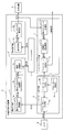
- FIG. 1 is a functional block diagram illustrating a video signal processing device according to the first embodiment of the present disclosure.
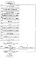
- FIG. 2 is a flowchart of video signal processing.
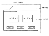
- FIG. 3 is a diagram showing a test pattern area
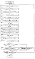
- FIG. 4 is a flowchart of video signal processing according to the second embodiment of the present disclosure.
- FIG. 5 is a diagram showing a test pattern area
- FIG. 6 is a flowchart of video signal processing according to the third embodiment of the present disclosure.
- FIG. 7 is a diagram showing a test pattern area.
- RGB signals input from the outside are protocol-converted into MIPI (registered trademark) (Mobile Industry Processor Interface) signals
- RGB signals are protocol-converted into LVDS (Low Voltage Differential Signaling) signals.
- MIPI registered trademark
- LVDS Low Voltage Differential Signaling
- An example of a configuration for output to the outside is illustrated, but the signal input from the outside may be a signal other than the RGB signal, and the signal output to the outside may be a signal other than the LVDS signal. Further, the signal processed internally may be a signal other than the MIPI signal.
- the video signal processing apparatus 1 has a signal processing circuit 2.
- the signal processing system circuit 2 includes a signal input unit 3, a frame memory 4, and a signal output unit 5.
- the video signal processing apparatus 1 also has a test pattern output unit 6 on the front side (input side) of the signal processing circuit 2 and a test pattern input unit on the rear side (output side) of the signal processing circuit 2. 7
- the functions of the signal input unit 3, the signal output unit 5, the test pattern output unit 6 and the test pattern input unit 7 are realized by circuits inside or outside the microcomputer. Each function can also be realized by a control program (including a diagnostic program) executed by the microcomputer.
- the video signal processing apparatus 1 switches between power-off (stop state) and power-on (start-up state) in conjunction with on / off of a vehicle-side switch (for example, an ACC (accessory) switch).
- the power off is a state waiting for a transition to power on, and is a state of operating with an operating power (low power consumption) lower than normal.
- the power-on is a state in which RGB signals input from the camera 8 (imaging unit) can be signal-processed, and is a state in which it operates with normal operating power.
- the camera 8 is a separate body from the video signal processing apparatus 1, and is a rear camera that is attached to the rear part of the vehicle body and images the rear of the vehicle, for example.
- the camera 8 images the rear of the vehicle and outputs RGB signals (video signals, video signals) including the captured images to the video signal processing device 1.
- the signal input unit 3 includes a first protocol conversion unit 3a, a second protocol conversion unit 3b, and a correction conversion unit 3c.
- the first protocol conversion unit 3 a performs protocol conversion of the input RGB signal from the RGB standard to the MIPI standard.
- the first protocol converter 3a outputs the MIPI signal generated by protocol conversion to the second protocol converter 3b.
- the second protocol conversion unit 3b converts the input MIPI signal from the MIPI standard to the RGB standard.
- the second protocol converter 3b outputs the RGB signal generated by the protocol conversion to the correction converter 3c or the frame memory 4.
- the correction conversion unit 3c performs correction conversion processing on the input RGB signal and outputs it to the frame memory 4.
- the correction conversion process is a process for adjusting, for example, the brightness and color of an image.
- the frame memory 4 is a buffer that temporarily stores RGB signal data.
- the frame memory 4 Store data temporarily.
- the signal output unit 5 includes a surface synthesis unit 5a and a third protocol conversion unit 5b.
- the surface synthesis unit 5 a performs a surface synthesis process on the input RGB signal and outputs it to the third protocol conversion unit 5 b.
- the surface compositing process is a process of superimposing additional information such as characters and guide lines on the video.
- the third protocol conversion unit 5b converts the input RGB signal from the RGB standard to the LVDS standard.
- the third protocol converter 5b outputs the LVDS signal (output signal) generated by the protocol conversion to the display device 9 (display unit) and the test pattern input unit 7.
- the display device 9 is installed in the passenger compartment, and when an LVDS signal is input from the video signal processing device 1 (signal output unit 5), it determines whether the input LVDS signal corresponds to a display region or a non-display region. . For the LVDS signal determined to fall within the display area, the display device 9 processes the LVDS signal and draws the video on the screen, thereby displaying the video behind the vehicle captured by the camera 8. That is, the driver (user) can recognize the state behind the vehicle (such as the presence or absence of an obstacle) by viewing the image behind the vehicle displayed on the display device 9. On the other hand, the display device 9 discards the LVDS signal that is determined to fall within the non-display area without performing signal processing on the LVDS signal.
- the test pattern output unit 6 and the test pattern input unit 7 are provided on the front side and the rear side of the signal processing circuit 2 as described above as functions for diagnosing the operation of the signal processing circuit 2.
- the test pattern output unit 6 includes a test pattern storage unit (library) 6a, a test pattern generation unit 6b, and a test pattern synthesis unit 6c.
- the test pattern storage unit 6a is also referred to as a storage unit
- the test pattern generation unit 6b is also referred to as a generation unit
- the test pattern synthesis unit 6c is also referred to as a synthesis unit.
- the test pattern storage unit 6a stores a plurality of test patterns.
- the test pattern is a test signal composed of a bit string having a predetermined number of bits of “0” and “1”.
- the test pattern generation unit 6b selects any one of a plurality of test patterns stored in the test pattern storage unit 6a, generates a test pattern, and outputs the test pattern to the test pattern synthesis unit 6c and the test pattern input unit 7. . That is, the same test pattern as the test pattern combined with the video signal is input to the test pattern input unit 7.
- the test pattern synthesis unit 6c When the test pattern is input from the test pattern generation unit 6b, the test pattern synthesis unit 6c combines (adds) the test pattern input from the test pattern generation unit 6b with the RGB signal input from the camera 8 to the signal input unit 3 Output to. That is, when the test pattern synthesizing unit 6c does not synthesize a test pattern, an RGB signal that is not synthesized with the test pattern is input to the circuit 2 of the signal processing system. On the other hand, the test pattern synthesizing unit 6c synthesizes the test pattern. When performing, the RGB signal combined with the test pattern is input to the signal processing circuit 2.
- the test pattern input unit 7 includes a fourth protocol conversion unit 7a, an inverse correction / inversion conversion unit 7b, and a test pattern comparison unit 7c.
- the test pattern comparison unit 7c is also referred to as a comparison unit.
- the fourth protocol conversion unit 7 a converts the input LVDS signal from the LVDS standard to the RGB standard.
- the fourth protocol converter 7a outputs the RGB signal generated by the protocol conversion to the reverse correction / inverse converter 7b.
- the reverse correction / inverse conversion unit 7b performs reverse correction / inverse conversion processing on the input RGB signal and outputs it to the test pattern comparison unit 7c.
- the reverse correction reverse conversion process is a process opposite to the correction conversion process performed by the correction conversion unit 3c.
- the test pattern comparison unit 7c extracts the test pattern from the input RGB signal.
- the test pattern comparison unit 7c compares the test pattern extracted from the RGB signal with the test pattern input from the test pattern output unit 6, and outputs the comparison result to the outside. In this case, the test pattern comparison unit 7c indicates that the comparison result is positive when the bit string of the test pattern extracted from the RGB signal and the bit string of the test pattern input from the test pattern output unit 6 completely match. A signal indicating that the comparison result is NO is output if the signal does not completely match.
- the signal indicating the comparison result output from the video signal processing device 1 is input to, for example, an ECU (Electronic Control Unit) that controls display on the meter panel. When the signal indicating that the comparison result is negative is input from the video signal processing device 1, the meter panel notifies the driver, for example, by turning on a warning lamp.
- the video signal processing device 1 In the activated state, the video signal processing device 1 is waiting for the start of the video signal processing shown in FIG. For example, when the driver switches the shift lever from a position other than the rear position (reverse position) to the rear position in order to move the vehicle backward, the video signal processing apparatus 1 receives a video signal processing start command from the outside. Start processing.
- the video signal processing apparatus 1 When starting the video signal processing, the video signal processing apparatus 1 generates a test pattern in the test pattern generation unit 6b (S1), and determines the test pattern synthesis position in the display area portion of the RGB signal input from the camera 8 (S2). Next, when the RGB signal is input from the camera 8, the video signal processing apparatus 1 combines the generated test pattern with the determined combined position for the input RGB signal (adds the test pattern to the RGB signal).
- the video signal processing apparatus 1 intentionally rewrites a part of the bit string (lower bits) constituting the RGB signal display area data, and modulates the RGB signal display area data with the test pattern (dither pattern). , Processing such as digital watermark). In other words, the video signal processing apparatus 1 modulates the data in the RGB signal display area to a predetermined level that cannot be discriminated by the driver or passengers by visual observation (so as not to be involved in the display of the output signal). Thus, the test pattern is synthesized with the data of the display area of the RGB signal.
- the video signal processing apparatus 1 converts the RGB signal combined with the test pattern from the RGB standard to the MIPI signal conforming to the MIPI standard by the first protocol conversion unit 3a (S4).
- the video signal processing apparatus 1 performs protocol conversion of the MIPI signal from the MIPI standard to the RGB signal conforming to the RGB standard by the second protocol conversion unit 3b (S5).
- the video signal processing apparatus 1 performs correction conversion processing on the RGB signal that needs correction conversion processing in the correction conversion unit 3c (S6), and temporarily stores the RGB signal data in the frame memory 4.
- the video signal processing apparatus 1 subjects the RGB signal input from the frame memory 4 to surface synthesis processing by the surface synthesis unit 5a (S7).
- the video signal processing apparatus 1 performs protocol conversion of the RGB signal from the RGB standard to the LVDS signal conforming to the LVDS standard by the third protocol conversion unit 5b (S8). At this time, by outputting the LVDS signal to the display device 9, an image behind the vehicle captured by the camera 8 is displayed on the display device 9.
- the video signal processing apparatus 1 performs protocol conversion of the LVDS signal from the LVDS standard to the RGB signal conforming to the RGB standard by the fourth protocol conversion unit 7a (S9).
- the video signal processing apparatus 1 performs reverse correction reverse conversion processing on the RGB signal that needs reverse correction reverse conversion processing in the reverse correction reverse conversion unit 7b (S10).
- the video signal processing apparatus 1 extracts a test pattern from the RGB signal by the test pattern comparison unit 7c (S11).
- the video signal processing apparatus 1 compares the test pattern extracted from the RGB signal with the test pattern input from the test pattern output unit 6 in the test pattern comparison unit 7c (S12, second procedure).
- the test pattern combined with the RGB signal does not change before and after passing through the signal processing circuit 2.
- the test pattern combined with the RGB signal changes before and after passing through the signal processing circuit 2. If the video signal processing apparatus 1 determines that the bit strings of both are completely coincident and the comparison result is positive (S13: YES), the video signal processing apparatus 1 outputs a signal indicating that the comparison result is positive (S14, Third procedure).
- the video signal processing apparatus 1 determines that the bit strings of both are not completely coincident and the comparison result is negative (S13: NO)
- the video signal processing apparatus 1 outputs a signal indicating that the comparison result is negative (S15). , Third procedure).
- the video signal processing apparatus 1 determines whether or not the video signal processing end condition is satisfied (S16). If the video signal processing device 1 determines that the processing end condition for the video signal processing is not satisfied (S16: NO), the video signal processing device 1 returns to step S1, and repeatedly executes step S1 and subsequent steps. On the other hand, in the video signal processing apparatus 1, for example, when the driver switches the shift lever from the rear position to a position other than the rear position and inputs a video signal processing end command from the outside, the video signal processing end condition is satisfied. (S16: YES), and the video signal processing is terminated.
- the test pattern does not change before and after passing through the signal processing circuit 2 (from input to output). That is, the test pattern combined with the video signal input to the signal processing system circuit 2 matches the test pattern extracted from the output signal output from the signal processing circuit 2.
- the signal processing circuit 2 is not operating normally (if an abnormality has occurred)
- the test pattern changes before and after passing through the signal processing circuit 2. That is, the test pattern combined with the video signal input to the signal processing circuit 2 does not match the test pattern extracted from the output signal output from the signal processing circuit 2.
- the test pattern is synthesized with the video signal input to the signal processing circuit 2 and the presence or absence of the test pattern change before and after passing through the signal processing circuit 2 is determined.
- the operation can be diagnosed in real time. Further, the user is not inconvenienced by synthesizing the test pattern with the video signal so as not to participate in the display of the output signal.
- the video signal processing apparatus 1 determines the test pattern synthesis position in the display area portion of the RGB signal input from the camera 8, so that the test pattern is displayed as shown in FIG. It will be reflected in the area. At this time, the video signal processing apparatus 1 modulates the display area portion of the RGB signal with a test pattern to such an extent that it cannot be discerned even if the driver or passenger sees it visually. None hold.
- FIG. 3 illustrates the case where the test pattern is reflected on the upper left end of the display area, the part that reflects the test pattern may be any part. Further, as long as the screen displays content and icons, the test pattern may be reflected on a portion (background) that avoids the content and icons.
- the video signal processing apparatus 1 determines the synthesis position of the test pattern in the RGB signal display area, and uses the RGB signal display area data as the driver or the
- the test pattern is synthesized with the RGB signal by modulating with the test pattern to such an extent that it cannot be discriminated even when the passenger visually observes it.
- the operation of the signal processing circuit 2 is diagnosed by determining whether or not the test pattern has changed before and after passing through the signal processing circuit 2. Thus, when the signal processing circuit 2 is in operation, the operation can be diagnosed in real time without causing any inconvenience to the driver or passenger.
- the RGB signal non-display area data may be discarded in order to effectively use the storage area of the frame memory 4. Since the synthesis position of the test pattern is determined in the display area, even if the data in the non-display area of the RGB signal is discarded, the operation of the signal processing circuit 2 can be suitably diagnosed. In addition, since any one of the plurality of test patterns is selected and the test pattern is generated, the contents of diagnosis can be changed by changing the test pattern.
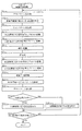
- the video signal processing apparatus 1 when the video signal processing apparatus 1 generates a test pattern in the test pattern generation unit 6b (S1), it detects the switching timing of the RGB signals by detecting the black image timing (S21).
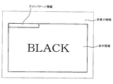
- the black screen timing is a display timing of a black screen ("BLACK" screen shown in FIG. 5) generated when switching a function such as switching from a navigation function to an audio function.
- the video signal processing apparatus 1 determines the synthesis position of the test pattern in the display area portion of the RGB signal input from the camera 8 at the switching timing of the RGB signal (S2). Then, the video signal processing apparatus 1 synthesizes the generated test pattern with the determined synthesis position for the RGB signal input from the camera 8 (S3), and thereafter, S4 and after described in the first embodiment. Execute.
- the video signal processing apparatus 1 determines the test pattern synthesis position in the RGB signal display area at the RGB signal switching timing, so as shown in FIG. It will be reflected in the display area. At this time, since the test pattern is synthesized at the switching timing of the RGB signals (so as not to be involved in the display of the output signal), the driver and passengers do not feel uncomfortable on the screen as in the first embodiment. .
- a test pattern is added to the RGB signal by synthesizing the test pattern in the RGB signal display area at the RGB signal switching timing. It was made to synthesize.
- the operation of the signal processing circuit 2 is diagnosed by determining whether or not the test pattern has changed before and after passing through the signal processing circuit 2.
- the operation can be diagnosed in real time without causing any inconvenience to the driver or passenger.
- the synthesis position of the test pattern is determined in the display area portion of the RGB signal, the operation of the signal processing circuit 2 can be performed even if the data in the non-display area of the RGB signal is discarded. Diagnosis can be suitably performed.
- the video signal processing apparatus 1 determines a test pattern synthesis position in a non-display area portion of the RGB signal input from the camera 8 (S31). . Then, the video signal processing apparatus 1 synthesizes the generated test pattern with the determined synthesis position for the RGB signal input from the camera 8 (S3), and thereafter, S4 and after described in the first embodiment. Execute.
- the video signal processing apparatus 1 determines the synthesis position of the test pattern in the non-display area portion of the RGB signal input from the camera 8 (so as not to be involved in the display of the output signal). As shown in FIG. 7, the test pattern is reflected in the non-display area, and the driver and the passenger do not feel discomfort on the screen as in the first embodiment. Although FIG. 7 illustrates the case where the test pattern is reflected on the upper left end of the non-display area, the part that reflects the test pattern may be any part.
- the test pattern is synthesized with the RGB signal by synthesizing the test pattern with the non-display area portion of the RGB signal. .
- the operation of the signal processing circuit 2 is diagnosed by determining whether or not the test pattern has changed before and after passing through the signal processing circuit 2. As a result, as in the first embodiment, when the signal processing circuit 2 is operating, the operation can be diagnosed in real time without causing any inconvenience to the driver or passenger.
- each part is expressed as, for example, S1. Furthermore, each part can be divided into a plurality of sub-parts, while the plurality of parts can be combined into one part. Furthermore, each part configured in this manner can be referred to as a circuit, a device, a module, and a means.
- Each of the above-mentioned plurality of parts or a combination thereof is not only (i) a software part combined with a hardware unit (for example, a computer), but also (ii) hardware (for example, an integrated circuit, As a part of the (wiring logic circuit), it can be realized with or without including the functions of related devices.
- the hardware unit can be configured inside a microcomputer.
- the video signal that is input from the rear camera that captures the rear of the vehicle is illustrated as an example, the video signal that is input from the front camera that captures the front of the vehicle and the side camera that captures the side of the vehicle is processed. May be.
- the configuration applied to the video signal processing device for a vehicle is illustrated, the configuration applied to a video signal processing device for uses other than the vehicle may be used.
- the configuration in which the RGB signal is input from the outside and the LVDS signal is output to the outside is illustrated, but the configuration may be a configuration in which the YUV signal is input from the outside, or an HDMI (registered trademark) (High-Definition Multimedia Interface) signal, It may be configured to output a GVIF (registered trademark) (Gigabit Video Interface) signal to the outside.
- HDMI registered trademark
- GVIF registered trademark
- a functional block of a signal processing system circuit may be configured in accordance with a signal to be employed.
- the functions realized by the internal or external circuit of the microcomputer of the present disclosure are stored in a computer-readable continuous and tangible storage medium for diagnosis of a control program (including a diagnostic program) executed by the microcomputer. It can also be provided as a program product.
- the diagnostic program product performs signal processing on a video signal input from the outside to generate an output signal, and outputs the generated output signal to the outside.
- the test pattern was synthesized with the video signal so that it was not involved in the display of the output signal on the computer, the test pattern synthesized with the video signal was compared with the test pattern extracted from the output signal, and synthesized with the video signal Instructions executed by a computer for outputting a comparison result between the test pattern and the test pattern extracted from the output signal are included.
Landscapes
- Engineering & Computer Science (AREA)
- Health & Medical Sciences (AREA)
- Biomedical Technology (AREA)
- General Health & Medical Sciences (AREA)
- Multimedia (AREA)
- Signal Processing (AREA)
- Testing, Inspecting, Measuring Of Stereoscopic Televisions And Televisions (AREA)
- Tests Of Electronic Circuits (AREA)
Abstract
映像信号処理装置は、外部からの映像信号を処理して出力信号を生成し、外部に出力する信号処理系の回路(2)と、出力信号の表示に関与しないように映像信号にテストパターンを合成する合成部(6c)と、映像信号に合成されたテストパターンと、出力信号から抽出されたテストパターンとを比較し、その比較結果を出力する比較部(7c)とを備える。具体的に、RGB信号の表示領域の部分にテストパターンの合成位置を決定し、RGB信号の表示領域のデータをユーザが目視しても判別不可能な程度にテストパターンで変調する(ディザパターン、電子透かし等の処理を施す)ことで、RGB信号にテストパターンを合成する。信号処理系の回路を通過する前後でのテストパターンの変化の有無を判定し、信号処理系の回路の動作を診断する。
Description
本出願は、2014年5月28日に出願された日本出願番号2014-110191号に基づくもので、ここにその記載内容を援用する。
本開示は、映像信号を信号処理する映像信号処理装置及び診断プログラム製品に関する。
例えばカメラから入力した映像信号を信号処理する映像信号処理装置においては、機能安全設計を行うに際して、信号処理系の回路が正常に動作していることを保障する必要がある。信号処理系の回路の動作を診断する構成として、信号処理系の回路とは別にテスト回路を設けた構成が開示されている(例えば特許文献1参照)。又、信号処理系の回路が動作中であるときに配線パターンの接続を診断する構成が開示されている(例えば特許文献2参照)。
特許文献1に開示されている技術では、信号処理系の回路とテスト回路とを切替える構成であるので、信号処理系の回路が動作中であるときには診断することができない。又、特許文献2に開示されている技術では、信号処理系の回路が動作中であるときに配線パターンの接続を診断する構成であるので、信号処理系の回路の動作を診断することができない。
本開示は、上記した事情に鑑みてなされたものであり、その目的は、信号処理系の回路が動作中であるときに、ユーザに不都合を与えることなく、その動作をリアルタイムに診断することができる映像信号処理装置及び診断プログラム製品を提供することにある。
本開示の一態様による映像信号処理装置は、信号処理系の回路と、合成部と、比較部と、を備える。信号処理系の回路は、外部から映像信号を入力すると、その入力した映像信号を信号処理して出力信号を生成し、その生成した出力信号を外部に出力する。合成部は、出力信号の表示に関与しないように映像信号にテストパターンを合成する。比較部は、映像信号に合成されたテストパターンと、出力信号から抽出されたテストパターンとを比較し、その比較結果を出力する。
上記装置によると、信号処理系の回路が動作中であるときに、ユーザに不都合を与えることなく、その動作をリアルタイムに診断することができる。
本開示の他の態様によるコンピュータ読み取り可能な持続的且つ有形の記憶媒体に保管されている診断プログラム製品は、外部から入力した映像信号を信号処理して出力信号を生成し、その生成した出力信号を外部に出力する信号処理系の回路を備えた映像信号処理装置のマイクロコンピュータに、出力信号の表示に関与しないように映像信号にテストパターンを合成し、映像信号に合成されたテストパターンと、出力信号から抽出されたテストパターンとを比較し、映像信号に合成されたテストパターンと出力信号から抽出されたテストパターンとの比較結果を出力するためのコンピュータによって実施される命令を含む。
上記プログラム製品によると、信号処理系の回路が動作中であるときに、ユーザに不都合を与えることなく、その動作をリアルタイムに診断することができる。
本開示についての上記目的およびその他の目的、特徴や利点は、添付の図面を参照しながら下記の詳細な記述により、より明確になる。その図面は、
図1は、本開示の第1の実施形態による映像信号処理装置を示す機能ブロック図であり、
図2は、映像信号処理のフローチャートであり、
図3は、テストパターン領域を示す図であり、
図4は、本開示の第2の実施形態による映像信号処理のフローチャートであり、
図5は、テストパターン領域を示す図であり、
図6は、本開示の第3の実施形態による映像信号処理のフローチャートであり、
図7は、テストパターン領域を示す図である。
(第1の実施形態)
以下、本開示を、車両に搭載される車両用の映像信号処理装置に適用した第1の実施形態について図1から図3を参照して説明する。尚、実施形態では、映像信号処理装置において、外部から入力したRGB信号をMIPI(登録商標)(Mobile Industry Processor Interface)信号にプロトコル変換し、RGB信号をLVDS(Low Voltage Differential Signaling)信号にプロトコル変換して外部に出力する構成を例示するが、外部から入力する信号はRGB信号以外の信号であっても良く、外部に出力する信号はLVDS信号以外の信号であっても良い。又、内部で処理する信号はMIPI信号以外の信号であっても良い。
以下、本開示を、車両に搭載される車両用の映像信号処理装置に適用した第1の実施形態について図1から図3を参照して説明する。尚、実施形態では、映像信号処理装置において、外部から入力したRGB信号をMIPI(登録商標)(Mobile Industry Processor Interface)信号にプロトコル変換し、RGB信号をLVDS(Low Voltage Differential Signaling)信号にプロトコル変換して外部に出力する構成を例示するが、外部から入力する信号はRGB信号以外の信号であっても良く、外部に出力する信号はLVDS信号以外の信号であっても良い。又、内部で処理する信号はMIPI信号以外の信号であっても良い。
映像信号処理装置1は、信号処理系の回路2を有する。信号処理系の回路2は、信号入力部3と、フレームメモリ4と、信号出力部5とを有する。又、映像信号処理装置1は、信号処理系の回路2の前段側(入力側)にテストパターン出力部6を有し、信号処理系の回路2の後段側(出力側)にテストパターン入力部7を有する。これら信号入力部3、信号出力部5、テストパターン出力部6及びテストパターン入力部7のそれぞれの機能は、マイクロコンピュータの内部又は外部の回路により実現される。尚、それぞれの機能は、マイクロコンピュータが実行する制御プログラム(診断プログラムを含む)により実現されることも可能である。又、映像信号処理装置1は、車両側のスイッチ(例えばACC(アクセサリ)スイッチ)のオンオフに連動して電源オフ(停止状態)と電源オン(起動状態)とを切替える。電源オフとは、電源オンへの移行を待機している状態であり、通常よりも低い動作電力(低消費電力)で動作する状態である。電源オンとは、カメラ8(撮像部)から入力するRGB信号を信号処理可能な状態であり、通常の動作電力で動作する状態である。
カメラ8は、映像信号処理装置1とは別体であり、例えば車体後部に取り付けられ、車両後方を撮像するリアカメラである。カメラ8は、車両後方を撮像し、その撮像した映像を含むRGB信号(映像信号、ビデオ信号)を映像信号処理装置1に出力する。
信号入力部3は、第1のプロトコル変換部3aと、第2のプロトコル変換部3bと、補正変換部3cとを有する。第1のプロトコル変換部3aは、カメラ8からテストパターン出力部6を介してRGB信号を入力すると、その入力したRGB信号をRGBの規格からMIPIの規格にプロトコル変換する。第1のプロトコル変換部3aは、プロトコル変換して生成したMIPI信号を第2のプロトコル変換部3bに出力する。第2のプロトコル変換部3bは、第1のプロトコル変換部3aからMIPI信号を入力すると、その入力したMIPI信号をMIPIの規格からRGBの規格にプロトコル変換する。第2のプロトコル変換部3bは、プロトコル変換して生成したRGB信号を補正変換部3c又はフレームメモリ4に出力する。補正変換部3cは、第2のプロトコル変換部3bからRGB信号を入力すると、その入力したRGB信号に補正変換処理を施してフレームメモリ4に出力する。補正変換処理とは、例えば映像の明るさや色彩を調整する処理である。
フレームメモリ4は、RGB信号のデータを一時的に記憶するバッファであり、信号入力部3(第2のプロトコル変換部3b又は補正変換部3c)からRGB信号を入力すると、その入力したRGB信号のデータを一時的に記憶する。
信号出力部5は、面合成部5aと、第3のプロトコル変換部5bとを有する。面合成部5aは、フレームメモリ4からRGB信号を入力すると、その入力したRGB信号に面合成処理を施して第3のプロトコル変換部5bに出力する。面合成処理とは、例えば文字やガイド線等の付加情報を映像に重ねる処理である。第3のプロトコル変換部5bは、面合成部5aからRGB信号を入力すると、その入力したRGB信号をRGBの規格からLVDSの規格にプロトコル変換する。第3のプロトコル変換部5bは、プロトコル変換して生成したLVDS信号(出力信号)を表示装置9(表示部)及びテストパターン入力部7に出力する。
表示装置9は、車室内に取り付けられ、映像信号処理装置1(信号出力部5)からLVDS信号を入力すると、その入力したLVDS信号が表示領域及び非表示領域の何れに該当するかを判定する。表示装置9は、表示領域に該当すると判定したLVDS信号については、そのLVDS信号を信号処理して映像を画面に描画することで、カメラ8が撮像した車両後方の映像を表示する。即ち、運転者(ユーザ)は、表示装置9に表示される車両後方の映像を目視することで、車両後方の様子(障害物の有無等)を認識することが可能となる。一方、表示装置9は、非表示領域に該当すると判定したLVDS信号については、そのLVDS信号を信号処理せずに破棄する。
テストパターン出力部6及びテストパターン入力部7は、信号処理系の回路2の動作を診断する機能として、上記したようにそれぞれ信号処理系の回路2の前段側及び後段側に設けられている。テストパターン出力部6は、テストパターン格納部(ライブラリ)6aと、テストパターン生成部6bと、テストパターン合成部6cとを有する。テストパターン格納部6aは格納部とも称し、テストパターン生成部6bは生成部とも称し、テストパターン合成部6cは、合成部とも称する。
テストパターン格納部6aは、複数のテストパターンを格納している。テストパターンは、「0」「1」の所定ビット数のビット列から構成される試験信号である。
テストパターン生成部6bは、テストパターン格納部6aに格納されている複数のテストパターンの中から何れかを選択し、テストパターンを生成してテストパターン合成部6c及びテストパターン入力部7に出力する。即ち、映像信号に合成されるテストパターンと同一のテストパターンがテストパターン入力部7に入力される。
テストパターン合成部6cは、テストパターン生成部6bからテストパターンを入力すると、カメラ8から入力したRGB信号にテストパターン生成部6bから入力したテストパターンを合成して(付加して)信号入力部3に出力する。即ち、テストパターン合成部6cがテストパターンの合成を行わないときには、テストパターンが合成されないRGB信号が信号処理系の回路2に入力されるが、一方、テストパターン合成部6cがテストパターンの合成を行うときには、テストパターンが合成されたRGB信号が信号処理系の回路2に入力される。
テストパターン入力部7は、第4のプロトコル変換部7aと、逆補正逆変換部7bと、テストパターン比較部7cとを有する。テストパターン比較部7cは、比較部とも称する。第4のプロトコル変換部7aは、信号出力部5からLVDS信号を入力すると、その入力したLVDS信号をLVDSの規格からRGBの規格にプロトコル変換する。第4のプロトコル変換部7aは、プロトコル変換して生成したRGB信号を逆補正逆変換部7bに出力する。逆補正逆変換部7bは、第4のプロトコル変換部7aからRGB信号を入力すると、その入力したRGB信号に逆補正逆変換処理を施してテストパターン比較部7cに出力する。逆補正逆変換処理とは、補正変換部3cが施した補正変換処理とは真逆の処理である。テストパターン比較部7cは、逆補正逆変換部7bからRGB信号を入力すると、その入力したRGB信号からテストパターンを抽出する。
テストパターン比較部7cは、そのRGB信号から抽出されたテストパターンと、テストパターン出力部6から入力したテストパターンとを比較し、その比較結果を外部に出力する。この場合、テストパターン比較部7cは、RGB信号から抽出されたテストパターンのビット列と、テストパターン出力部6から入力したテストパターンのビット列とが完全一致である場合には比較結果が正である旨を示す信号を出力し、完全一致でない場合には比較結果が否である旨を示す信号を出力する。尚、映像信号処理装置1から出力された比較結果を示す信号は、例えばメータパネルの表示を制御するECU(Electronic Control Unit)に入力される。メータパネルは、映像信号処理装置1から比較結果が否である旨の信号を入力すると、例えば警告灯を点灯させる等して運転者に報知する。
次に、上記した構成の作用について、図2及び図3も参照して説明する。
映像信号処理装置1は、起動状態では、図2に示す映像信号処理の開始を待機している。映像信号処理装置1は、例えば運転者が車両を後退させるべくシフトレバーをリア位置(後退位置)以外からリア位置へと切替えたことで、外部から映像信号処理の開始指令を入力すると、映像信号処理を開始する。映像信号処理装置1は、映像信号処理を開始すると、テストパターンをテストパターン生成部6bにて生成し(S1)、カメラ8から入力するRGB信号の表示領域の部分にテストパターンの合成位置を決定する(S2)。次いで、映像信号処理装置1は、カメラ8からRGB信号を入力すると、その入力したRGB信号に対し、その生成したテストパターンを当該決定した合成位置に合成する(RGB信号にテストパターンを付加する)(S3、第1の手順)。このとき、映像信号処理装置1は、RGB信号の表示領域のデータを構成するビット列の一部(下位ビット)を意図的に書き換え、RGB信号の表示領域のデータをテストパターンで変調する(ディザパターン、電子透かし等の処理を施す)。即ち、映像信号処理装置1は、RGB信号の表示領域のデータを運転者や同乗者が目視しても判別不可能な所定レベルに(出力信号の表示に関与しないように)テストパターンで変調することで、RGB信号の表示領域のデータにテストパターンを合成する。
次いで、映像信号処理装置1は、テストパターンが合成されたRGB信号を、RGBの規格からMIPIの規格に準拠するMIPI信号に第1のプロトコル変換部3aにてプロトコル変換する(S4)。次いで、映像信号処理装置1は、MIPI信号を、MIPIの規格からRGBの規格に準拠するRGB信号に第2のプロトコル変換部3bにてプロトコル変換する(S5)。次いで、映像信号処理装置1は、補正変換処理が必要なRGB信号に補正変換処理を補正変換部3cにて施し(S6)、RGB信号のデータをフレームメモリ4に一時的に記憶する。次いで、映像信号処理装置1は、フレームメモリ4から入力したRGB信号に面合成処理を面合成部5aにて施す(S7)。次いで、映像信号処理装置1は、RGB信号を、RGBの規格からLVDSの規格に準拠するLVDS信号に第3のプロトコル変換部5bにてプロトコル変換する(S8)。このとき、LVDS信号が表示装置9に出力されることで、カメラ8が撮像した車両後方の映像が表示装置9に表示される。
次いで、映像信号処理装置1は、LVDS信号を、LVDSの規格からRGBの規格に準拠するRGB信号に第4のプロトコル変換部7aにてプロトコル変換する(S9)。次いで、映像信号処理装置1は、逆補正逆変換処理が必要なRGB信号に逆補正逆変換処理を逆補正逆変換部7bにて施す(S10)。次いで、映像信号処理装置1は、RGB信号からテストパターンをテストパターン比較部7cにて抽出する(S11)。次いで、映像信号処理装置1は、そのRGB信号から抽出したテストパターンとテストパターン出力部6から入力したテストパターンとをテストパターン比較部7cにて比較する(S12、第2の手順)。
この場合、信号処理系の回路2が正常に動作していれば、RGB信号に合成されたテストパターンは信号処理系の回路2を通過する前後で変化することはない。一方、信号処理系の回路2が正常に動作していなければ(異常が発生していれば)、RGB信号に合成されたテストパターンは信号処理系の回路2を通過する前後で変化する。映像信号処理装置1は、両者のビット列が完全一致であると判定し、比較結果が正であると判定すると(S13:YES)、比較結果が正である旨を示す信号を出力する(S14、第3の手順)。一方、映像信号処理装置1は、両者のビット列が完全一致でないと判定し、比較結果が否であると判定すると(S13:NO)、比較結果が否である旨を示す信号を出力する(S15、第3の手順)。
そして、映像信号処理装置1は、映像信号処理の処理終了条件が成立したか否かを判定する(S16)。映像信号処理装置1は、映像信号処理の処理終了条件が成立していないと判定すると(S16:NO)、ステップS1に戻り、ステップS1以降を繰返して実行する。一方、映像信号処理装置1は、例えば運転者がシフトレバーをリア位置からリア位置以外へと切替えたことで、外部から映像信号処理の終了指令を入力すると、映像信号処理の処理終了条件が成立したと判定し(S16:YES)、映像信号処理を終了する。
上記したように、信号処理系の回路2が正常に動作していれば、テストパターンは信号処理系の回路2を通過する前後で(入力から出力までの処理で)変化することはない。即ち、信号処理系の回路2に入力される映像信号に合成されたテストパターンと、信号処理系の回路2から出力された出力信号から抽出されたテストパターンとは一致する。一方、信号処理系の回路2が正常に動作していなければ(異常が発生していれば)、テストパターンは信号処理系の回路2を通過する前後で変化する。即ち、信号処理系の回路2に入力される映像信号に合成されたテストパターンと、信号処理系の回路2から出力された出力信号から抽出されたテストパターンとは一致しない。これにより、信号処理系の回路2に入力される映像信号にテストパターンを合成し、信号処理系の回路2を通過する前後でのテストパターンの変化の有無を判定することで、信号処理系の回路2が動作中であるときに、その動作をリアルタイムに診断することができる。又、出力信号の表示に関与しないように映像信号にテストパターンを合成することで、ユーザに不都合を与えることもない。
以上に説明した映像信号処理では、映像信号処理装置1は、カメラ8から入力するRGB信号の表示領域の部分にテストパターンの合成位置を決定するので、図3に示すように、テストパターンを表示領域に反映することになる。このとき、映像信号処理装置1は、RGB信号の表示領域の部分を運転者や同乗者が目視しても判別不可能な程度にテストパターンで変調するので、運転者や同乗者が画面に違和感を抱くことはない。尚、図3では、テストパターンを表示領域の上左端部に反映した場合を例示しているが、テストパターンを反映する部位は何れの部位であっても良い。又、コンテンツやアイコンを表示する画面であれば、テストパターンをコンテンツやアイコンを避けた部位(背景)に反映しても良い。
以上に説明したように第1の実施形態によれば、映像信号処理装置1において、RGB信号の表示領域の部分にテストパターンの合成位置を決定し、RGB信号の表示領域のデータを運転者や同乗者が目視しても判別不可能な程度にテストパターンで変調することで、RGB信号にテストパターンを合成するようにした。そして、信号処理系の回路2を通過する前後でのテストパターンの変化の有無を判定することで、信号処理系の回路2の動作を診断するようにした。これにより、信号処理系の回路2が動作中であるときに、運転者や同乗者に不都合を与えることなく、その動作をリアルタイムに診断することができる。
又、RGB信号のデータをフレームメモリ4に一時的に記憶する際に、フレームメモリ4の記憶領域を有効利用すべくRGB信号の非表示領域のデータを破棄することもあり得るが、RGB信号の表示領域の部分にテストパターンの合成位置を決定するようにしたので、RGB信号の非表示領域のデータを破棄したとしても、信号処理系の回路2の動作を好適に診断することができる。又、複数のテストパターンの中から何れかを選択し、テストパターンを生成するようにしたので、テストパターンを変化させることで、診断の内容に変化を持たせることができる。
(第2の実施形態)
次に、本開示の第2の実施形態について、図4及び図5を参照して説明する。尚、上記した第1の実施形態と同一部分については説明を省略し、異なる部分について説明する。第2の実施形態は、RGB信号の切替タイミングでRGB信号の表示領域のデータにテストパターンを合成する点で第1の実施形態とは異なる。
次に、本開示の第2の実施形態について、図4及び図5を参照して説明する。尚、上記した第1の実施形態と同一部分については説明を省略し、異なる部分について説明する。第2の実施形態は、RGB信号の切替タイミングでRGB信号の表示領域のデータにテストパターンを合成する点で第1の実施形態とは異なる。
即ち、映像信号処理装置1は、テストパターンをテストパターン生成部6bにて生成すると(S1)、黒画タイミングを検知することで、RGB信号の切替タイミングを検知する(S21)。黒画タイミングとは、例えばナビゲーションの機能からオーディオの機能に切替える等の機能を切替える際に発生する黒画(図5に示す「BLACK」の画面)の表示タイミングである。次いで、映像信号処理装置1は、そのRGB信号の切替タイミングで、カメラ8から入力するRGB信号の表示領域の部分にテストパターンの合成位置を決定する(S2)。そして、映像信号処理装置1は、カメラ8から入力したRGB信号に対し、その生成したテストパターンを当該決定した合成位置に合成し(S3)、これ以降、第1の実施形態で説明したS4以降を実行する。
以上に説明した映像信号処理では、映像信号処理装置1は、RGB信号の切替タイミングでRGB信号の表示領域の部分にテストパターンの合成位置を決定するので、図5に示すように、テストパターンを表示領域に反映することになる。このとき、RGB信号の切替タイミングで(出力信号の表示に関与しないように)テストパターンを合成するので、第1の実施形態と同様に、運転者や同乗者が画面に違和感を抱くことはない。
以上に説明したように第2の実施形態によれば、映像信号処理装置1において、RGB信号の切替タイミングでRGB信号の表示領域の部分にテストパターンを合成することで、RGB信号にテストパターンを合成するようにした。そして、信号処理系の回路2を通過する前後でのテストパターンの変化の有無を判定することで、信号処理系の回路2の動作を診断するようにした。これにより、第1の実施形態と同様に、信号処理系の回路2が動作中であるときに、運転者や同乗者に不都合を与えることなく、その動作をリアルタイムに診断することができる。又、この場合も、RGB信号の表示領域の部分にテストパターンの合成位置を決定するようにしたので、RGB信号の非表示領域のデータを破棄したとしても、信号処理系の回路2の動作を好適に診断することができる。
(第3の実施形態)
次に、本開示の第3の実施形態について、図6及び図7を参照して説明する。尚、上記した第1の実施形態と同一部分については説明を省略し、異なる部分について説明する。第3の実施形態は、RGB信号の非表示領域のデータにテストパターンを合成する点で第1の実施形態とは異なる。
次に、本開示の第3の実施形態について、図6及び図7を参照して説明する。尚、上記した第1の実施形態と同一部分については説明を省略し、異なる部分について説明する。第3の実施形態は、RGB信号の非表示領域のデータにテストパターンを合成する点で第1の実施形態とは異なる。
即ち、映像信号処理装置1は、テストパターンをテストパターン生成部6bにて生成すると(S1)、カメラ8から入力するRGB信号の非表示領域の部分にテストパターンの合成位置を決定する(S31)。そして、映像信号処理装置1は、カメラ8から入力したRGB信号に対し、その生成したテストパターンを当該決定した合成位置に合成し(S3)、これ以降、第1の実施形態で説明したS4以降を実行する。
以上に説明した映像信号処理では、映像信号処理装置1は、カメラ8から入力するRGB信号の非表示領域の部分に(出力信号の表示に関与しないように)テストパターンの合成位置を決定するので、図7に示すように、テストパターンを非表示領域に反映することになり、第1の実施形態と同様に、運転者や同乗者が画面に違和感を抱くことはない。尚、図7では、テストパターンを非表示領域の上左端部に反映した場合を例示しているが、テストパターンを反映する部位は何れの部位であっても良い。
以上に説明したように第3の実施形態によれば、映像信号処理装置1において、RGB信号の非表示領域の部分にテストパターンを合成することで、RGB信号にテストパターンを合成するようにした。そして、信号処理系の回路2を通過する前後でのテストパターンの変化の有無を判定することで、信号処理系の回路2の動作を診断するようにした。これにより、第1の実施形態と同様に、信号処理系の回路2が動作中であるときに、運転者や同乗者に不都合を与えることなく、その動作をリアルタイムに診断することができる。
本開示に記載されるフローチャート、あるいは、フローチャートの処理は、複数の部(あるいはステップと言及される)から構成され、各部は、たとえば、S1と表現される。さらに、各部は、複数のサブ部に分割されることができる、一方、複数の部が合わさって一つの部にすることも可能である。さらに、このように構成される各部は、サーキット、デバイス、モジュール、ミーンズとして言及されることができる。
また、上記の複数の部の各々あるいは組合わさったものは、(i) ハードウエアユニット(例えば、コンピュータ)と組み合わさったソフトウエアの部のみならず、(ii) ハードウエア(例えば、集積回路、配線論理回路)の部として、関連する装置の機能を含みあるいは含まずに実現できる。さらに、ハードウエアの部は、マイクロコンピュータの内部に構成されることもできる。
(その他の実施形態)
本開示は、上記した実施形態にのみ限定されるものではなく、以下のように変形又は拡張することができる。
本開示は、上記した実施形態にのみ限定されるものではなく、以下のように変形又は拡張することができる。
車両後方を撮像するリアカメラから入力した映像信号を信号処理する構成を例示したが、車両前方を撮像するフロントカメラや車両側方を撮像するサイドカメラから入力した映像信号を信号処理する構成であっても良い。
車両用の映像信号処理装置に適用する構成を例示したが、車両以外の用途の映像信号処理装置に適用する構成であっても良い。
外部からRGB信号を入力し、LVDS信号を外部に出力する構成を例示したが、外部からYUV信号を入力する構成であっても良いし、HDMI(登録商標)(High-Definition Multimedia Interface)信号やGVIF(登録商標)(Gigabit Video Interface)信号を外部に出力する構成であっても良い。即ち、外部から入力する映像信号や外部に出力する出力信号はどのようなフォーマットの信号を採用しても良い。又、採用する信号に応じて信号処理系の回路の機能ブロックを構成すれば良い。
さらに、本開示のマイクロコンピュータの内部又は外部の回路により実現される機能は、マイクロコンピュータが実行する制御プログラム(診断プログラムを含む)をコンピュータ読み取り可能な持続的且つ有形の記憶媒体に保管して診断プログラム製品として提供することも可能である。具体的に、診断プログラム製品は、外部から入力した映像信号を信号処理して出力信号を生成し、その生成した出力信号を外部に出力する信号処理系の回路を備えた映像信号処理装置のマイクロコンピュータに、出力信号の表示に関与しないように映像信号にテストパターンを合成し、映像信号に合成されたテストパターンと、出力信号から抽出されたテストパターンとを比較し、映像信号に合成されたテストパターンと出力信号から抽出されたテストパターンとの比較結果を出力するためのコンピュータによって実施される命令を含む。
本開示は、実施例に準拠して記述されたが、本開示は当該実施例や構造に限定されるものではないと理解される。本開示は、様々な変形例や均等範囲内の変形をも包含する。加えて、様々な組み合わせや形態、さらには、それらに一要素のみ、それ以上、あるいはそれ以下、を含む他の組み合わせや形態をも、本開示の範畴や思想範囲に入るものである。
Claims (7)
- 外部から入力した映像信号を信号処理して出力信号を生成し、その生成した出力信号を外部に出力する信号処理系の回路(2)と、
前記出力信号の表示に関与しないように前記映像信号にテストパターンを合成する合成部(6c)と、
前記映像信号に合成されたテストパターンと、前記出力信号から抽出されたテストパターンとを比較し、その比較結果を出力する比較部(7c)と、を備えた映像信号処理装置。 - 請求項1に記載した映像信号処理装置において、
複数のテストパターンを格納する格納部(6a)と、
前記格納部に格納されている複数のテストパターンのうち何れかを選択することで前記テストパターンを生成する生成部(6b)と、をさらに備え、
前記合成部は、前記映像信号に前記生成部により生成されたテストパターンを合成する映像信号処理装置。 - 請求項1又は2に記載した映像信号処理装置において、
前記合成部は、前記映像信号の表示領域の部分をテストパターンで変調することで、前記出力信号の表示に関与しないように前記映像信号にテストパターンを合成する映像信号処理装置。 - 請求項1又は2に記載した映像信号処理装置において、
前記合成部は、前記映像信号の切替タイミングで前記映像信号の表示領域の部分にテストパターンを合成することで、前記出力信号の表示に関与しないように前記映像信号にテストパターンを合成する映像信号処理装置。 - 請求項1又は2に記載した映像信号処理装置において、
前記合成部は、前記映像信号の非表示領域の部分にテストパターンを合成することで、前記出力信号の表示に関与しないように前記映像信号にテストパターンを合成する映像信号処理装置。 - 請求項1から5の何れか一項に記載した映像信号処理装置において、
前記信号処理系の回路は、車両後方を撮像する撮像部(8)から入力した映像信号を信号処理して出力信号を生成し、その生成した出力信号を表示部(9)に出力する映像信号処理装置。 - 外部から入力した映像信号を信号処理して出力信号を生成し、その生成した出力信号を外部に出力する信号処理系の回路(2)を備えた映像信号処理装置(1)のマイクロコンピュータに、
前記出力信号の表示に関与しないように前記映像信号にテストパターンを合成し、
前記映像信号に合成されたテストパターンと、前記出力信号から抽出されたテストパターンとを比較し、
前記映像信号に合成されたテストパターンと前記出力信号から抽出されたテストパターンとの比較結果を出力するための
コンピュータによって実施される命令を含み、コンピュータ読み取り可能な持続的且つ有形の記憶媒体に保管されている診断プログラム製品。
Priority Applications (1)
| Application Number | Priority Date | Filing Date | Title |
|---|---|---|---|
| DE112015002465.4T DE112015002465T5 (de) | 2014-05-28 | 2015-05-21 | Videosignalverarbeitungseinrichtung und Diagnoseprogrammprodukt |
Applications Claiming Priority (2)
| Application Number | Priority Date | Filing Date | Title |
|---|---|---|---|
| JP2014110191A JP6446837B2 (ja) | 2014-05-28 | 2014-05-28 | 映像信号処理装置及び診断プログラム |
| JP2014-110191 | 2014-05-28 |
Publications (1)
| Publication Number | Publication Date |
|---|---|
| WO2015182082A1 true WO2015182082A1 (ja) | 2015-12-03 |
Family
ID=54698437
Family Applications (1)
| Application Number | Title | Priority Date | Filing Date |
|---|---|---|---|
| PCT/JP2015/002563 WO2015182082A1 (ja) | 2014-05-28 | 2015-05-21 | 映像信号処理装置及び診断プログラム製品 |
Country Status (3)
| Country | Link |
|---|---|
| JP (1) | JP6446837B2 (ja) |
| DE (1) | DE112015002465T5 (ja) |
| WO (1) | WO2015182082A1 (ja) |
Cited By (1)
| Publication number | Priority date | Publication date | Assignee | Title |
|---|---|---|---|---|
| CN106686376A (zh) * | 2016-12-23 | 2017-05-17 | 惠州市德赛西威汽车电子股份有限公司 | 一种视频信号自动测试工具 |
Families Citing this family (4)
| Publication number | Priority date | Publication date | Assignee | Title |
|---|---|---|---|---|
| JPWO2019092851A1 (ja) * | 2017-11-10 | 2020-05-28 | 三菱電機株式会社 | 監視カメラ診断システム |
| JP7109272B2 (ja) * | 2018-06-18 | 2022-07-29 | ローム株式会社 | 半導体集積回路、ブリッジチップ、ディスプレイシステム、自動車 |
| US11025900B2 (en) * | 2018-07-18 | 2021-06-01 | Universal City Studios Llc | System and method for identifying b-roll conditions in live streams or live rendered content |
| JP7419721B2 (ja) * | 2018-12-20 | 2024-01-23 | セイコーエプソン株式会社 | 回路装置、電子機器及び移動体 |
Citations (6)
| Publication number | Priority date | Publication date | Assignee | Title |
|---|---|---|---|---|
| JPH0541036A (ja) * | 1991-02-07 | 1993-02-19 | Sony Corp | 信号処理装置 |
| JPH07131828A (ja) * | 1993-11-05 | 1995-05-19 | Matsushita Electric Ind Co Ltd | 映像信号監視装置 |
| JPH11168616A (ja) * | 1997-12-03 | 1999-06-22 | Toshiba Corp | 画像情報処理方法および画像情報処理装置 |
| WO2007102485A1 (ja) * | 2006-03-06 | 2007-09-13 | Anritsu Corporation | 試験信号発生装置 |
| JP2011091594A (ja) * | 2009-10-22 | 2011-05-06 | Fujitsu Ltd | 画像処理装置、画像処理方法、および画像処理プログラム |
| JP2014082678A (ja) * | 2012-10-17 | 2014-05-08 | Nippon Telegr & Teleph Corp <Ntt> | マーカー埋め込み装置、マーカー検出装置、マーカー埋め込み方法、マーカー検出方法、及びプログラム |
-
2014
- 2014-05-28 JP JP2014110191A patent/JP6446837B2/ja active Active
-
2015
- 2015-05-21 WO PCT/JP2015/002563 patent/WO2015182082A1/ja active Application Filing
- 2015-05-21 DE DE112015002465.4T patent/DE112015002465T5/de not_active Ceased
Patent Citations (6)
| Publication number | Priority date | Publication date | Assignee | Title |
|---|---|---|---|---|
| JPH0541036A (ja) * | 1991-02-07 | 1993-02-19 | Sony Corp | 信号処理装置 |
| JPH07131828A (ja) * | 1993-11-05 | 1995-05-19 | Matsushita Electric Ind Co Ltd | 映像信号監視装置 |
| JPH11168616A (ja) * | 1997-12-03 | 1999-06-22 | Toshiba Corp | 画像情報処理方法および画像情報処理装置 |
| WO2007102485A1 (ja) * | 2006-03-06 | 2007-09-13 | Anritsu Corporation | 試験信号発生装置 |
| JP2011091594A (ja) * | 2009-10-22 | 2011-05-06 | Fujitsu Ltd | 画像処理装置、画像処理方法、および画像処理プログラム |
| JP2014082678A (ja) * | 2012-10-17 | 2014-05-08 | Nippon Telegr & Teleph Corp <Ntt> | マーカー埋め込み装置、マーカー検出装置、マーカー埋め込み方法、マーカー検出方法、及びプログラム |
Cited By (1)
| Publication number | Priority date | Publication date | Assignee | Title |
|---|---|---|---|---|
| CN106686376A (zh) * | 2016-12-23 | 2017-05-17 | 惠州市德赛西威汽车电子股份有限公司 | 一种视频信号自动测试工具 |
Also Published As
| Publication number | Publication date |
|---|---|
| JP2015226206A (ja) | 2015-12-14 |
| DE112015002465T5 (de) | 2017-02-09 |
| JP6446837B2 (ja) | 2019-01-09 |
Similar Documents
| Publication | Publication Date | Title |
|---|---|---|
| WO2015182082A1 (ja) | 映像信号処理装置及び診断プログラム製品 | |
| JP5148328B2 (ja) | 表示制御装置、表示制御方法、表示制御プログラム及びコンピュータ読み取り可能な記録媒体 | |
| US8854466B2 (en) | Rearward view assistance apparatus displaying cropped vehicle rearward image | |
| WO2014068856A1 (ja) | 画像生成装置、および画像生成プログラム製品 | |
| JP2008017311A (ja) | 車両用映像表示装置及び車両周囲映像の表示方法 | |
| US20200404192A1 (en) | Vehicle-mounted device | |
| JP6459283B2 (ja) | 映像信号処理装置及び映像信号処理プログラム | |
| US20170208293A1 (en) | Semiconductor device, video display system, and method of processing signal | |
| US20160198126A1 (en) | Vehicular image control apparatus | |
| WO2016021133A1 (ja) | 映像信号処理装置及び映像信号処理プログラム製品 | |
| US10464483B2 (en) | On-vehicle image processing device | |
| WO2016021134A1 (ja) | 映像信号処理装置及び映像信号処理プログラム製品 | |
| US9779464B2 (en) | Camera image display system of audio video navigation | |
| WO2016092770A1 (ja) | 映像信号処理装置及び映像信号処理プログラム | |
| JP2009124377A (ja) | 車両周辺画像処理装置及び車両周辺状況提示方法 | |
| JP2012089985A (ja) | 表示制御装置及び制御装置 | |
| JP2009130436A (ja) | 車両用画像表示システム | |
| US20230206880A1 (en) | Information processing apparatus and information processing method | |
| JP2016207040A (ja) | 画像処理装置、画像処理方法および車載装置 | |
| JP2019156235A (ja) | 表示制御装置、撮像装置、カメラモニタリングシステムおよびコンピュータプログラム | |
| JP4919064B2 (ja) | 車両用表示装置 | |
| JP2005033594A (ja) | 移動体周辺表示装置 | |
| CN117097852A (zh) | 一种汽车电子仪表屏的图标显示方法及装置 | |
| CN117508018A (zh) | 车辆的全视野电子后视镜装置、控制方法、车辆及设备 | |
| JP2009027649A (ja) | 車両用表示装置 |
Legal Events
| Date | Code | Title | Description |
|---|---|---|---|
| 121 | Ep: the epo has been informed by wipo that ep was designated in this application |
Ref document number: 15798957 Country of ref document: EP Kind code of ref document: A1 |
|
| WWE | Wipo information: entry into national phase |
Ref document number: 112015002465 Country of ref document: DE |
|
| 122 | Ep: pct application non-entry in european phase |
Ref document number: 15798957 Country of ref document: EP Kind code of ref document: A1 |