WO2015178743A1 - 액화가스 처리 시스템 - Google Patents
액화가스 처리 시스템 Download PDFInfo
- Publication number
- WO2015178743A1 WO2015178743A1 PCT/KR2015/005217 KR2015005217W WO2015178743A1 WO 2015178743 A1 WO2015178743 A1 WO 2015178743A1 KR 2015005217 W KR2015005217 W KR 2015005217W WO 2015178743 A1 WO2015178743 A1 WO 2015178743A1
- Authority
- WO
- WIPO (PCT)
- Prior art keywords
- gas
- boil
- liquefied
- liquefied gas
- supplied
- Prior art date
- Legal status (The legal status is an assumption and is not a legal conclusion. Google has not performed a legal analysis and makes no representation as to the accuracy of the status listed.)
- Ceased
Links
Images
Classifications
-
- B—PERFORMING OPERATIONS; TRANSPORTING
- B63—SHIPS OR OTHER WATERBORNE VESSELS; RELATED EQUIPMENT
- B63B—SHIPS OR OTHER WATERBORNE VESSELS; EQUIPMENT FOR SHIPPING
- B63B21/00—Tying-up; Shifting, towing, or pushing equipment; Anchoring
- B63B21/24—Anchors
- B63B21/38—Anchors pivoting when in use
-
- B—PERFORMING OPERATIONS; TRANSPORTING
- B63—SHIPS OR OTHER WATERBORNE VESSELS; RELATED EQUIPMENT
- B63B—SHIPS OR OTHER WATERBORNE VESSELS; EQUIPMENT FOR SHIPPING
- B63B25/00—Load-accommodating arrangements, e.g. stowing, trimming; Vessels characterised thereby
- B63B25/02—Load-accommodating arrangements, e.g. stowing, trimming; Vessels characterised thereby for bulk goods
- B63B25/08—Load-accommodating arrangements, e.g. stowing, trimming; Vessels characterised thereby for bulk goods fluid
- B63B25/12—Load-accommodating arrangements, e.g. stowing, trimming; Vessels characterised thereby for bulk goods fluid closed
- B63B25/16—Load-accommodating arrangements, e.g. stowing, trimming; Vessels characterised thereby for bulk goods fluid closed heat-insulated
-
- F—MECHANICAL ENGINEERING; LIGHTING; HEATING; WEAPONS; BLASTING
- F17—STORING OR DISTRIBUTING GASES OR LIQUIDS
- F17C—VESSELS FOR CONTAINING OR STORING COMPRESSED, LIQUEFIED OR SOLIDIFIED GASES; FIXED-CAPACITY GAS-HOLDERS; FILLING VESSELS WITH, OR DISCHARGING FROM VESSELS, COMPRESSED, LIQUEFIED, OR SOLIDIFIED GASES
- F17C7/00—Methods or apparatus for discharging liquefied, solidified, or compressed gases from pressure vessels, not covered by another subclass
- F17C7/02—Discharging liquefied gases
Definitions
- the present invention relates to a liquefied gas treatment system.
- liquefied gas such as liquefied natural gas and liquefied petroleum gas has been widely used in place of gasoline or diesel according to technology development.
- Liquefied natural gas is liquefied by cooling methane obtained by refining natural gas collected from a gas field. It is a colorless and transparent liquid.
- Liquefied petroleum gas is a liquid fuel made by compressing a gas mainly composed of propane (C3H8) and butane (C4H10), which come with oil from an oil field, at room temperature.
- Liquefied petroleum gas like liquefied natural gas, is colorless and odorless and is widely used as a fuel for household, business, industrial, and automobile use.
- Such liquefied gas is stored in a liquefied gas storage tank installed on the ground or in a liquefied gas storage tank provided in a ship which is a means of transporting the ocean, and liquefied natural gas is liquefied to a volume of 1/600.
- the liquefied petroleum gas is reduced by the liquefied propane is 1/260, butane is reduced to a volume of 1/230 has the advantage of high storage efficiency.
- Such liquefied gas is supplied and used to various demand sources.
- an LNG fuel supply method for driving an engine using LNG as fuel in LNG carriers carrying liquefied natural gas has been developed. The method used is being applied to other vessels other than LNG carriers.
- the temperature and pressure of the liquefied gas required by the customer such as the engine may be different from the state of the liquefied gas stored in the liquefied gas storage tank. Therefore, in recent years, continuous research and development has been made regarding a technology for controlling the temperature and pressure of a liquefied gas stored in a liquid state and supplying it to a demand destination.
- IMO International Maritime Organization
- IMO Tier III Total Air Pollution Prevention
- EEDI Energy Efficiency Design Index
- An object of the present invention is to provide a liquefied gas treatment system for supplying fuel gas supplied to an engine with fuel of a gas combustion device for heating exhaust gas supplied to an SCR.
- the liquefied gas processing system according to an embodiment of the present invention, the fuel supply device for processing the liquefied gas or evaporated gas supplied to the demand destination in the liquefied gas storage tank; And a gas combustion device which receives liquefied gas or evaporated gas from the liquefied gas storage tank or the fuel supply device and burns the combustion gas, thereby improving an exhaust temperature delivered to the purification unit from the demand destination.
- the gas combustion device is supplied with the liquefied gas or the boil-off gas in a mixed state and burned, and the purifying unit may be SCR (Selective Catalytic Reduction).
- the fuel supply apparatus the liquefied gas processing device for supplying to the demand destination after the liquefied gas stored in the liquefied gas storage tank pressurized by a pump and vaporized through a vaporizer; And an evaporative gas treatment device for pressurizing the evaporated gas generated in the liquefied gas storage tank with an evaporative gas compressor and supplying the evaporated gas to the demand destination, wherein the gas combustion device is liquefied from the liquefied gas processing device or the evaporated gas processing device. It can be burned by receiving gas or boil-off gas.
- the boil-off gas compressor is composed of a plurality of stages and pressurized in multiple stages, and the gas-fired apparatus may receive the boil-off gas branched between at least one stage of the boil-off gas compressor and burn it.
- the gas combustion device may be supplied with a liquefied gas pressurized by the pump and combusted.
- the boil-off gas liquefier for liquefying at least a portion by expanding or reducing the boil-off gas pressurized by the boil-off gas compressor;
- a first gas-liquid separator separating liquid and gas gas from the boil-off gas passing through the boil-off gas liquefier;
- an evaporating gas heat exchanger for recovering the cold heat of the boil-off gas supplied from the liquefied gas storage tank and the cold heat of the gas gas supplied from the first gas-liquid separator by the boil-off gas pressurized by the boil-off gas compressor.
- the combustion device may receive at least a portion of the gaseous gas supplied from the first gas-liquid separator and combust it.
- the gas supply apparatus may further include a nitrogen regulator configured to receive at least a portion of the gaseous gas supplied from the first gas-liquid separator and separate nitrogen from the gas combustion apparatus.
- the gas combustion device may receive at least a portion of the gaseous gas supplied from the nitrogen regulator. May burn.
- the liquefied gas processing apparatus may include a temporary storage tank provided between the liquefied gas storage tank and the pump, and the gas combustion apparatus may receive and receive the boil-off gas generated from the temporary storage tank. have.
- the forced vaporizer for vaporizing the liquefied gas stored in the liquefied gas storage tank; And a second gas-liquid separator for receiving liquefied gas from the forced vaporizer to filter heavy carbon (HHC), and supplying liquefied gas having a high methane value to the demand source, wherein the gas combustion device includes a gas-liquid separator from the second gas-liquid separator.
- the combustion gas may be supplied and combusted, or the methane gas liquefied gas supplied from the second gas-liquid separator to the demand source may be combusted.
- the waste heat recovery device may be further driven by using a heat source supplied from the purification unit.
- the waste heat recovery apparatus for generating steam by using the heat source;
- a turbine for generating rotational force by using steam supplied from the economizer;
- a generator for generating electric power by using the rotational force generated by the turbine;
- it may include a condenser for condensing the steam discharged from the turbine.
- the liquefied gas treatment system according to the present invention has the effect of enabling an optimized function of the SCR by heating the exhaust gas supplied to the SCR with a gas combustion device, and supplying the fuel gas supplied with the fuel of the gas combustion device to the engine.
- a gas combustion device supplying the fuel gas supplied with the fuel of the gas combustion device to the engine.
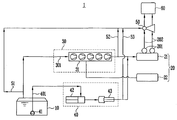
- FIG. 1 is a conceptual diagram of a liquefied gas treatment system according to a first embodiment of the present invention.
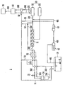
- FIG. 2 is a conceptual diagram of a liquefied gas treatment system according to a second embodiment of the present invention.
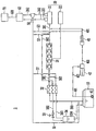
- FIG. 3 is a conceptual diagram of a liquefied gas treatment system according to a third embodiment of the present invention.
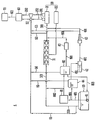
- FIG. 4 is a conceptual diagram of a liquefied gas treatment system according to a fourth embodiment of the present invention.
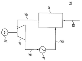
- FIG. 5 is a WHRS conceptual diagram of a liquefied gas treatment system according to an embodiment of the present invention.
- FIG. 1 is a conceptual diagram of a liquefied gas treatment system according to a first embodiment of the present invention.
- the liquefied gas treatment system 1 includes a liquefied gas storage tank 10, a demand destination 20, an evaporative gas treatment device 30, and a liquefied gas treatment device. 40, a gas combustion device 50, and a purification unit 60.
- liquefied gas may be used to encompass all gaseous fuels which are generally stored in a liquid state, such as LNG or LPG, ethylene, ammonia, and the like. Can be expressed as This can be applied to the boil-off gas as well.
- LNG may be used for the purpose of encompassing not only liquid NG (Natural Gas) but also supercritical NG, for convenience, and evaporation gas may be used to include not only gaseous evaporation gas but also liquefied evaporation gas.
- the gas gas may be a flash gas.
- the liquefied gas storage tank 10 stores the liquefied gas to be supplied to the demand destination 20.
- the liquefied gas storage tank 10 should store the liquefied gas in a liquid state, where the liquefied gas storage tank 10 may have a pressure tank form.
- the liquefied gas storage tank 10 may be increased in internal pressure as the liquefied gas stored therein is evaporated to generate an evaporated gas, and may be designed in such a manner as to withstand the internal pressure.
- the demand destination 20 receives the evaporated gas and the liquefied gas supplied from the liquefied gas storage tank 10 and uses it as fuel.
- the demand source 20 may be a high pressure gas injection engine (eg, MEGI).
- crank shaft (not shown) connected to the piston As the engine reciprocates the piston (not shown) inside the cylinder (not shown) by combustion of the liquefied gas, a crank shaft (not shown) connected to the piston is rotated, and a shaft (not shown) is connected to the crank shaft. May not be rotated. Therefore, as the propeller (not shown) connected to the shaft rotates when the customer 20 drives, the hull may move forward or backward.
- the demand source 20 may be an engine for driving the propeller, but may be an engine for power generation or an engine for generating other power.
- the present embodiment does not particularly limit the type of the demand destination 20.
- the demand source 20 may be an internal combustion engine generating a driving force by combustion of boil-off gas, liquefied gas, flash gas and oil.
- the demand destination 20 can obtain the driving force by receiving the boil-off gas and flash gas pressurized by the boil-off gas compressor 31 which will be described later.
- the states of the boil-off gas and the flash gas supplied to the customer 20 may vary depending on the condition required by the customer 20.
- the demand source 20 may include a high pressure demand destination 21 and a low pressure demand destination 22.
- the high pressure demand destination 21 is a demand destination 21 using a high pressure evaporation gas of about 300 bar, for example, may be a MEGI engine, may use the evaporation gas supplied from the liquefied gas storage tank 10, and pressurized And heated liquefied gas may be used.
- the high pressure demand 21 may be a double fuel engine (DF engine) capable of using double fuel.
- Dual fuel engines are typically two-stroke DF engines driven by diesel cycles. In this diesel cycle, basically, air is compressed by a piston, and the compressed hot air is ignited by a pilot fuel, and the remaining high-pressure gas is injected to explode.
- the ignition fuel uses HFO (Heavy Fuel Oil) or MDO (Marine Diesel Oil), the ratio of the ignition fuel and the high-pressure gas is about 5:95, the injection amount of the ignition fuel is adjusted to 5 ⁇ 100%. It is possible.
- the ignition fuel is therefore also available as a driving fuel for the engine.
- evaporated gas or heated liquefied gas; about 95%) is mainly used as the engine driving fuel, and when the injection amount of the ignition fuel is 100%, the engine driving fuel is ignited.
- the fuel (oil) is used up.
- the injection amount of the ignition fuel is about 50% (and about 50% of the boil-off gas)
- the ignition fuel and the boil-off gas are not mixed and flow into the engine, but the ignition fuel ignites first to produce a calorific value, and then the rest The gas enters and explodes to produce a calorific value to produce the calorific value required to drive the engine.
- the low pressure demand destination 22 is a demand destination 20 using a low pressure boil-off gas of about 7 to 10 bar, and may be, for example, a DFDE engine.
- the low pressure demand destination 22 is a dual fuel engine which can use dual fuel, and can use not only liquefied gas but oil as a fuel.
- the low pressure demand destination 22 may be driven by receiving the boil-off gas discharged from the middle end of the boil-off gas compressor 31 to be described later.
- the engine 20 will be described below with respect to the customer 20 for pressure, combustion temperature, stroke, RPM, and fuel mixing.
- the demand source 20 may be a 2sDF engine or a 4sDF engine, and may be discharged after the exhaust, that is, the waste heat source, is used through the turbocharger 201 provided in each engine.
- the exhaust exhausted directly from each engine, that is, the waste heat source may have a temperature of about 3 to 400 degrees by the exhaust of high temperature and high pressure, the exhaust of the high temperature and high pressure drives the turbocharger 201 and thereby energy It can be taken away and have a temperature of about 240 to 270 degrees.
- the exhaust, that is, the waste heat source may be supplied to the purification unit 60 to be described later through the waste heat source supply line 202.
- the 2sDF engine burns fast, resulting in very high temperatures during compression, which can cause NOx (nitrogen oxides) in the exhaust.
- the 4sDF engine may not generate NOx in the exhaust through premixed combustion due to the low combustion temperature due to the slow combustion, but NOx occurs in the exhaust when burned with oil.
- the exhaust gas of the 4sDF engine may also pass through the purification unit 60.
- the NOx is classified as an important air pollutant, and is purified by the purification unit 60 to be described later and discharged to the outboard. This will be described in detail in the purification unit 60.
- NOx may be generated for each driving of the engine, and all engines in which the NOx is generated may be applied to the demand destination 20.
- the boil-off gas treating apparatus 30 processes boil-off gas supplied from the liquefied gas storage tank 10 to the demand destination 20, and may include an boil-off gas compressor 31 and a boil-off gas first line 301. .
- the boil-off gas treatment apparatus 30 may pressurize the boil-off gas supplied from the liquefied gas storage tank 10 by the boil-off gas compressor 31 and supply the boil-off gas to the demander 20 through the boil-off gas first line 301.
- the boil-off gas compressor 31 pressurizes the boil-off gas generated in the liquefied gas storage tank 10.
- the boil-off gas compressor 31 may pressurize the boil-off gas generated and discharged from the liquefied gas storage tank 10 and supply the boil-off gas to the boil-off gas heat exchanger 32 or the customer 20.
- the boil-off gas compressor 31 is provided in plurality, and can pressurize the boil-off gas in multiple stages.
- the evaporation gas compressor 31 may be provided with five to allow the evaporation gas to be pressurized five times.
- the five-stage pressurized boil-off gas may be pressurized to 200 bar to 400 bar and supplied to the customer 20 through the boil-off gas first line 301.
- An evaporating gas cooler (not shown) may be provided between the plurality of evaporating gas compressors 31.
- the boil-off gas When the boil-off gas is pressurized by the boil-off gas compressor 31, since the temperature may also increase as the pressure rises, the present embodiment may lower the temperature of the boil-off gas using the boil-off gas cooler.
- the boil-off gas cooler may be installed in the same number as the boil-off gas compressor 31, and each boil-off gas cooler may be provided downstream of each boil-off gas compressor 31.
- the boil-off gas compressor 31 pressurizes the boil-off gas, the boil-off gas rises in pressure to increase its boiling point, thereby allowing it to be liquefied even at a relatively high temperature. Therefore, the present embodiment can increase the pressure of the boil-off gas with the boil-off gas compressor 31 so that the boil-off gas can be easily liquefied.
- the first boil-off gas line 301 may be provided with a valve (not shown) on the line, and the valve may control the flow rate of the boil-off gas supplied to the demand destination 20 through opening degree control.
- the liquefied gas processing apparatus 40 processes the liquefied gas supplied from the liquefied gas storage tank 10 to the demand destination 20, and may include a boosting pump 41, a high pressure pump 42, and a vaporizer 43. have.
- the liquefied gas processing device 40 supplies the liquefied gas stored in the liquefied gas storage tank 10 to the high pressure pump 42 through the boosting pump 41, and pressurizes the liquefied gas to a high pressure in the high pressure pump 42.
- the liquefied gas may be vaporized in the post-vaporizer 43 to be supplied to the demand destination 20.
- the liquefied gas processing device 40 may further include a liquefied gas first line 401.
- the liquefied gas first line 401 may be provided with a valve (not shown) on the line, and the valve may control the flow rate of the liquefied gas by adjusting the opening degree, and may be a three-way valve.
- the boosting pump 41 may be provided on the liquefied gas first line 401 in a reciprocating manner or may be provided in the liquefied gas storage tank 10 in a latent manner, and is sufficient for the high pressure pump 42 to be described later. A positive amount of liquefied gas may be supplied to prevent cavitation of the high pressure pump 42. In addition, the boosting pump 41 may extract the liquefied gas from the liquefied gas storage tank 10 to pressurize the liquefied gas to several to several tens of bar, and preferably to 1 to 25 bar.
- the high pressure pump 42 is provided in the liquefied gas first line 401 and pressurizes the liquefied gas in the liquid state pressurized by the boosting pump 41 to the vaporizer 43 which will be described later. At this time, the high-pressure pump 42 pressurizes the liquefied gas to the demand destination 20, for example, 200 bar to 400 bar, and supplies the liquefied gas to the demand destination 20 so that the demand destination 20 generates power through the liquefied gas. You can do that.
- the vaporizer 43 is provided on the liquefied gas first line 401 and heat exchanges the liquefied gas with a heat exchange medium.
- the vaporizer 43 may be provided in the liquefied gas supply line 16 between the demand source 20 and the high pressure pump 42 and heat exchanges the liquefied gas supplied from the high pressure pump 42 by using a heat exchange medium. 20) can be supplied.
- the vaporizer 43 can heat the liquefied gas while maintaining 200 bar to 400 bar, which is the pressure discharged from the high pressure pump 42, and heat the liquefied gas to 30 ° to 60 ° and then supply it to the customer 20.
- the gas combustion device 50 receives the liquefied gas or the boiled gas from the liquefied gas storage tank 10, the boil-off gas processing device 30, or the liquefied gas processing device 40, and burns the gas. Raise the exhaust temperature delivered to 60.
- the gas combustion device 50 may be supplied with a liquefied gas or an evaporated gas mixed and combusted.
- the gas combustion device 50 may be used as combustion heat by receiving various fuels to increase the exhaust temperature transferred from the demand source 20 to the purification unit 60, and the first and third gas combustion fuel lines described below. 51-53) can be supplied with fuel.
- the gas combustion device 50 may further include a gas combustion fuel first line 51, a gas combustion fuel second line 52, and a gas combustion fuel third line 53.
- Each line 51 to 53 may be provided with a valve (not shown) on the line, and the valve may control the flow rate of the fluid supplied to the gas combustion device 50 through the opening degree adjustment.
- the gas combustion device 50 supplies the boil-off gas or the liquefied gas stored in the liquefied gas storage tank 10 through the gas combustion fuel first line 51 (which can be vaporized and supplied through a forced vaporizer (not shown)). It can be used to generate the heat of combustion by receiving the boil-off gas pressurized by the boil-off gas compressor 31 through the gas combustion fuel second line 52 to generate the heat of combustion. It is pressurized by the high pressure pump 42 via the line 53, and can be used to generate the combustion heat by receiving the gas vaporized by the vaporizer 43.
- the gas combustion device 50 may be supplied with various fuels through the first to third lines 51 to 53 of the gas combustion fuel described above, and used as combustion heat, and from this to the purification unit 60 from the demand source 20. It is possible to effectively increase the exhaust temperature to be delivered.
- the exhaust gas of the engine passes through the turbocharger 201, so that the temperature is lower than the optimum temperature for the purification unit 60 to react with the Nox catalyst. 60, the purification section 60 needs heat of reaction, and therefore, a heat source for heating the exhaust gas is required before the exhaust gas is supplied.
- the exhaust gas supplied to the purification unit 60 through the gas combustion device 50 is heated, and the first to third lines 51 to 3 of the gas combustion fuel as the fuel of the gas combustion device 50.
- the surplus evaporation gas or the surplus liquefied gas supplied through 53 there is an effect of preventing the waste of fuel and the efficient use of energy.
- the purification unit 60 may receive and purify the exhaust gas supplied from the demand source 20 in a state of being further heated by the gas combustion device 50.
- the purification unit 60 may be SCR (Selective Catalytic Reduction), but is not limited thereto.
- the purification unit 60 may receive and purify the exhaust gas supplied from the demand source 20 in a state of being further heated by the gas combustion device 50.
- the demand source 20 may be an engine, and the fuel used in the engine is NOx (nitrogen oxide) emitted during the combustion process.
- NOx nitrogen oxide
- Such NOx has stable N2O, NO, N2O3, NO2, N2O5 and the like and unstable NO3.
- NO and NO2 nitrogen oxides.
- High concentrations of nitrogen oxides cause photochemical reactions, form mists, and cause secondary damage, so nitrogen oxides are classified as important air pollutants.
- Influence of nitrogen oxides causes smog by photochemical decomposition, absorbs visible light, reduces visibility, and discolors or corrodes the material.
- the plant is damaged damage to the cells, leaf discoloration, carbon assimilation ability, and humans are mainly causing toxic effects to the lungs.
- the purification unit 60 of the embodiment of the present invention may be selective catalytic reduction (SCR).
- nitrogen oxide contained in exhaust gas generated from the customer 20 can be used as a reducing agent (ammonia can be used as a reducing agent, but not limited thereto, and CO, H2, HC, etc. can also be used). After the reaction with the catalyst is converted into harmless nitrogen and water vapor and discharged.
- the purification unit 60 has an advantage that the processing efficiency is very high, such as 80% or more, and has a very large effect by the denitrification technique.
- IMO Tier III regulations will be effective in IMO, so that the purification unit 60 may be most effective to satisfy this.
- the purification unit 60 since the purification unit 60 generates the highest reaction efficiency at the reaction temperature of approximately 300 to 400 degrees, the temperature is increased by the additional heating of the gas combustion device 50 to the exhaust gas discharged from the engine of the demand destination 20. Exhaust gases may be most suitable.
- the nitrogen demand (not shown) and the nitrogen discharge line (not shown) for connecting the nitrogen demand and the purification unit 60 and the nitrogen demand further comprises: Can be.
- the nitrogen separated by the purification unit 60 may be supplied to the nitrogen demand through the nitrogen discharge line.
- the nitrogen stored in the nitrogen source may serve to seal various machines (not shown), or may insulate and seal the cold heat or liquefied gas storage tank 10 of the reliquefaction device (not shown). Can be done.
- the nitrogen source can include the devices described above. However, since it can be used in a ship for a wide variety of purposes other than the above-described action, the nitrogen demand destination that requires nitrogen is not limited to the above-described devices.
- Purification unit 60 there is an effect to prevent the exhaust gas produced in the customer destination 20 is discharged to the outside causing environmental pollution and at the same time can satisfy the IMO Tier III regulations.
- the purification unit 60 may produce nitrogen required by a ship (not shown) through purification of exhaust gas, thereby reducing the cost of purchasing nitrogen.
- the liquefied gas treatment system 1 is equipped with a purification unit 60 to reduce the nitrogen oxides discharged to the outside through the exhaust gas is optimized for IMO Tier III regulations to be fermented later It can work.
- the exhaust gas supplied to the purification unit 60 is heated by the gas combustion device 50 has the effect that the optimized function of the purification unit 60 can be realized.
- the combustion source for driving the gas combustion device 50 through the surplus gases in the vessel, such as surplus flash gas, surplus evaporation gas, there is an effect that can improve the energy efficiency of the vessel, and prevent the waste of fuel. .
- FIG. 2 is a conceptual diagram of a liquefied gas treatment system according to a second embodiment of the present invention
- FIG. 5 is a conceptual diagram of a WHRS of a liquefied gas treatment system according to an embodiment of the present invention.
- the liquefied gas processing system 2 according to the embodiment of the present invention, the liquefied gas storage tank 10, the customer 20, the boil-off gas processing apparatus 30, liquefied gas
- cleaning part 60, and the waste heat recovery apparatus 70 are included.
- the configuration of the liquefied gas storage tank 10, the demand destination 20 is the same or similar to the first embodiment.
- Components that are the same as or correspond to the above-described embodiments are denoted by the same reference numerals, and redundant description thereof will be omitted.
- the boil-off gas treatment apparatus 30 processes boil-off gas supplied from the liquefied gas storage tank 10 to the demand destination 20, and includes a boil-off gas compressor 31, a boil-off gas heat exchanger 32, and a boil-off gas liquefier ( 33), may include a first gas-liquid separator (34).
- the boil-off gas treatment device 30 may pressurize the boil-off gas supplied from the liquefied gas storage tank 10 through the boil-off gas compressor 31 and supply it to the demand destination 20, and pressurize it through the boil-off gas compressor 31.
- the boil-off evaporated gas to the boil-off gas heat exchanger 32 to exchange heat with the boil-off gas supplied from the liquefied gas storage tank 10
- the heat-exchanged boil-off gas is reduced or expanded through the boil-off gas liquefier 33
- the liquid can be liquefied, and the reliquefied boil-off gas can be separated into the gas phase and the liquid phase in the first gas-liquid separator 34.
- the boil-off gas treatment apparatus 30 may further include a boil-off gas first line 301, a boil-off gas second line 302, and a gas-gas first line 303.
- Each line 301, 302, 303 may be provided with a valve (not shown) on the line, the valve may control the flow rate of the boil-off gas or gas gas through the opening degree adjustment, it may be a three-way valve.
- the boil-off gas compressor 31 has the same contents as described in the first embodiment of the present invention, so that it is replaced with this.
- the boil-off gas heat exchanger 32 is provided between the liquefied gas storage tank 10 and the boil-off gas compressor 31 on the boil-off gas first line 301 and pressurized by the boil-off gas compressor 31.
- the boil-off gas supplied from the liquefied gas storage tank 10 may be heat-exchanged.
- the boil-off gas exchanged in the boil-off gas heat exchanger 32 may be supplied to the boil-off gas liquefier 33. That is, the boil-off gas heat exchanger 32 is the boil-off gas recovered along the second boil-off gas 302 pressurized by the boil-off gas compressor 31 and branched upstream of the demand source 20, and the liquefied gas storage tank ( Heat exchange the boil-off gas supplied in 10).
- the boil-off gas heat exchanger 30 may cool the boil-off gas recovered along the boil-off gas second line 302 with the boil-off gas supplied from the liquefied gas storage tank 10.
- the boil-off gas liquefier 33 depressurizes or expands the boil-off gas pressurized by the boil-off gas compressor 31 and heat-exchanged in the boil-off gas heat exchanger 32 to liquefy at least a portion.
- the boil-off gas liquefier 33 may depressurize the boil-off gas to 1 bar to 10 bar, and the boil-off gas may be reduced to 1 bar when the boil-off gas is liquefied and transferred to the liquefied gas storage tank 10. Cooling effect can be achieved.
- the boil-off gas pressurized by the boil-off gas compressor 31 is cooled by heat-exchanging with the boil-off gas supplied from the liquefied gas storage tank 10 in the boil-off gas heat exchanger 32, but the pressure is discharged from the boil-off gas compressor 31. Discharged pressure can be maintained.
- the boil-off gas is reduced by using the boil-off gas liquefier 33 to cool the boil-off gas, thereby liquefying the boil-off gas.
- the larger the pressure range to be reduced in pressure may increase the cooling effect of the boil-off gas, for example, the boil-off gas liquefier 33 may reduce the boil-off gas pressurized to 300bar by the boil-off compressor 31 to 1bar.
- the boil-off gas liquefier 33 may consist of a Joule Thompson valve.
- the boil-off gas liquefier 33 may be made up of an expander (not shown).
- the reduced pressure can effectively cool the boil-off gas so that at least a portion of the boil-off gas is liquefied.
- the inflator may also be made of an expander (not shown).
- the expander can be driven without using a separate power, in particular, by utilizing the generated power as the power for driving the boil-off gas compressor 31, it is possible to improve the efficiency of the liquefied gas treatment system (2).
- Power transmission may be achieved, for example, by gear connection or after electric conversion.
- the first gas-liquid separator 34 separates gas from the boil-off gas expanded or reduced in the boil-off gas liquefier 33.
- the boil-off gas is separated into a liquid and a gas, and the liquid is supplied to the liquefied gas storage tank 10, and the gas is recovered upstream of the boil-off gas heat exchanger 32 as a flash gas or a gas combustion device 50 may be supplied.
- the boil-off gas supplied to the first gas-liquid separator 34 may be in a state of being cooled under reduced pressure in the boil-off gas liquefier 33.
- the boil-off gas may be pressurized in multiple stages to have a pressure of 200 bar to 400 bar, and the temperature may be about 45 degrees.
- the boil-off gas raised to a temperature of about 45 degrees is recovered by the boil-off gas heat exchanger 32 and heat-exchanged with the boil-off gas around -100 degrees supplied from the liquefied gas storage tank 10, and cooled to a temperature of around -97 degrees And is supplied to the boil-off gas liquefier 33.
- the boil-off gas in the boil-off gas liquefier 33 may be cooled by the reduced pressure may have a pressure of about 1bar and a temperature of about -162.3 degrees.
- the boil-off gas supplied to the first gas-liquid separator 34 is decompressed in the boil-off gas liquefier 33 to have a temperature lower than ⁇ 162 degrees, about 30-40% of the boil-off gas is liquefied. Can be.
- the liquefied gas is recovered to the liquefied gas storage tank 10, and the evaporated gas heat exchanger on the boil-off gas first line 301 without discarding the flash gas generated in the first gas-liquid separator 34 ( 32) It may be recovered to the front end, pressurized by the boil-off gas and flash gas through the boil-off gas compressor 40 and then supplied to the demand destination 20, or may be supplied to the gas combustion device 50 and combusted.
- the liquefied gas and the flash gas respectively form the gas gas first line 303, the gas combustion fuel fourth line 54 and the liquefied gas return line 304.
- the liquefied gas first line 301 may be recovered to the front end of the boil-off gas heat exchanger 32 or to the liquefied gas storage tank (10).
- the liquefied gas return line 304 is connected from the first gas-liquid separator 34 to the liquefied gas storage tank 10 to recover the liquefied gas to the liquefied gas storage tank 10, and the gas gas first line 303 is
- the first gas-liquid separator 34 is connected to the front end of the boil-off gas heat exchanger 32 on the boil-off gas first line 301 to recover the flash gas
- the fourth gas-fuel fuel line 54 is the first gas-liquid separator. It is connected to the gas combustion fuel first line 51 at 34 to recover the flash gas, thereby preventing the flash gas from being discarded and wasted.
- Embodiments of the present invention may further include a nitrogen regulator (not shown).
- the nitrogen regulator may be supplied with at least a portion of flash gas, that is, gas gas, supplied from the first gas-liquid separator 34 by a gas gas second line (not shown), and separated by separating nitrogen from the supplied gas gas.
- Nitrogen is supplied to a nitrogen demand source (not shown), and at least a portion of the degassed gas gas may be returned to the gas gas first line 303 by a gas gas third line (not shown), and nitrogen may be The remaining gas gas may be supplied to the gas combustion device 50.
- the nitrogen regulator can smoothly burn in the gas combustion device 50 by removing nitrogen as an inert gas and supplying the same to the gas combustion device 50.
- the liquefied gas processing device 40 processes the liquefied gas supplied from the liquefied gas storage tank 10 to the demand destination 20, and includes a boosting pump 41, a high pressure pump 42, a vaporizer 43, and a temporary storage tank. And (44).
- the liquefied gas processing device 40 supplies the liquefied gas stored in the liquefied gas storage tank 10 to the high pressure pump 42 through the boosting pump 41, and pressurizes the liquefied gas to a high pressure in the high pressure pump 42.
- the liquefied gas may be vaporized in the post-vaporizer 43 to be supplied to the demand destination 20.
- the boosting pump 41, the high pressure pump 42, and the vaporizer 43 are the same as or similar to those described in the first embodiment of the present invention, and are thus replaced.
- the gas combustion device 50 receives the liquefied gas or the boiled gas from the liquefied gas storage tank 10, the boil-off gas processing device 30, or the liquefied gas processing device 40, and burns the gas. Improve exhaust temperature delivered to 60.
- the gas combustion device 50 may be supplied with a liquefied gas or an evaporated gas mixed and combusted.
- Gas combustion device 50 may be used as the heat of combustion by receiving a variety of heat sources to improve the exhaust temperature delivered to the purification unit 60 from the demand source 20, the first to fourth gas combustion fuel line (described below) 51–54) can provide a heat source.
- the gas combustion device 50 further includes a gas combustion fuel first line 51, a gas combustion fuel second line 52, a gas combustion fuel third line 53, and a gas combustion fuel fourth line 54. can do.
- Each line 51 to 54 may be provided with a valve (not shown) on the line, the valve may control the flow rate of the fluid supplied to the gas combustion device 50 through the opening degree adjustment, It may be a valve.
- the gas combustion device 50 may be used to generate combustion heat by receiving the liquefied gas stored in the liquefied gas storage tank 10 through the first gas burned fuel line 51, and the second gas burned fuel line 52. Can be used to generate the combustion heat by receiving the boil-off gas pressurized by the boil-off gas compressor (31), pressurized by the high-pressure pump (42) through the gas combustion fuel third line (53), 43) can be used to generate the heat of combustion by receiving the liquefied gas vaporized by.
- the gas combustion device 50 may be used to generate combustion heat by receiving the flash gas separated from the first gas-liquid separator 34 through the gas combustion fuel fourth line 54. That is, by using the flash gas generated in the process of reliquefaction through the boil-off gas heat exchanger 32 as the heat of combustion, it is possible to prevent the waste of fuel and to use energy efficiently.
- the gas combustion device 50 may be supplied with various heat sources through the first to fourth lines 51 to 54 of the above-described gas combustion fuel and used as combustion heat, and from this to the purification unit 60 from the demand source 20.
- the exhaust temperature delivered can be effectively improved.
- the purification unit 60 may receive and purify the exhaust gas supplied from the demand source 20 in a state of being further heated by the gas combustion device 50.
- the purification unit 60 may be SCR (Selective Catalytic Reduction), but is not limited thereto.
- the purifying unit 60 may supply the heat source to the waste heat recovery device 70 after purifying the exhaust gas supplied from the demand source 20 by being further heated by the gas combustion device 50.
- the nitrogen separated by the purification unit 60 may be supplied to the nitrogen demand through the nitrogen discharge line, purification unit ( Since the water vapor separated by 60 contains a high temperature, it may be supplied to the waste heat recovery device 70 which will be described later through the heat source supply line 601.
- Purification unit 60 can produce the nitrogen required by the ship (not shown) through the purification of the exhaust gas has the effect of reducing the cost of purchasing nitrogen, waste heat generated and preserved in the purification reaction will be described later Through the waste heat recovery device 70 can be reused in the power production and propulsion unit operation, such that the efficient energy utilization is possible.
- the waste heat recovery system 70 may be driven by using a heat source supplied from the purification unit 60. Specifically, the waste heat recovery system 70 may be purified from the purification unit 60 and supplied from the gas combustion device 50. The exhaust gas of the demand source 20 heated by additional heating (hereinafter, used as a waste heat source) may be supplied and driven.
- FIG. 4 is a WHRS conceptual diagram of a liquefied gas treatment system according to an embodiment of the present invention.
- the waste heat recovery device 70 may include an economizer 71, a turbine 72, a generator 721, and a condenser 73.
- the economizer 71 generates steam using the waste heat source
- the turbine 72 generates a rotational force using the steam supplied from the economizer 71
- the generator 721 is the turbine 72. Electric power can be generated by using the rotational force generated by)
- the condenser 73 can condense the steam discharged from the turbine 72.
- the waste heat recovery device 70 may include a steam circulation line 701.
- the steam circulation line 701 may include an economizer 71, a turbine 72, and a condenser 73.
- the high temperature water vapor purified by the purification unit 60 is supplied to the economizer 71 through the heat source supply line 601, and the economizer 71 applies an additional heat source to the high temperature water vapor to supply the turbine 72.
- the turbine 72 receives a high temperature water vapor to generate a rotational force, and the generated rotational force generates power or generates propulsion through the generator 721.
- Water vapor discharged from the turbine 72 is supplied to the condenser 73 through the steam circulation line 701, the water vapor from the condenser 73 is condensed back to the economizer 71 through the steam circulation line 701 Supplied.
- the waste heat recovery device 70 may generate power or generate thrust through the generator 721 using a heat source supplied from the purification unit 60, thereby maximizing energy use of a vessel (not shown). Can be.
- the liquefied gas treatment system 2 the gas combustion device which is driven to increase the reaction heat of the purification unit 60 flash gas generated in the process of reliquefaction through the boil-off gas heat exchanger ( By using the combustion heat of 50), there is an effect of preventing waste of fuel and enabling efficient use of energy.
- the liquefied gas processing system 2 includes a WHRS 70 to burn the exhaust gas and the flash gas of the engine 20 and maximize energy efficiency by using waste heat of the exhaust gas discharged.
- a purification unit 60 to reduce the nitrogen oxides discharged to the outside through the exhaust gas can be optimized in the IMO Tier III regulations to be fermented in the future.
- FIG. 3 is a conceptual diagram of a liquefied gas treatment system according to a third embodiment of the present invention.
- the liquefied gas treatment system 3 includes a liquefied gas storage tank 10, a demand destination 20, an evaporative gas treatment device 30, and a liquefied gas treatment device ( 40, a gas combustion device 50, a purification unit 60, and a waste heat recovery device 70.
- a configuration other than the boil-off gas heat exchanger 32, the first gas-liquid separator 34, the gas combustion device 50, the gas combustion fuel seventh line 57 and the gas gas first line 303 is the second. It is the same as or similar to the embodiment. Components that are the same as or correspond to the above-described embodiments are denoted by the same reference numerals, and redundant description thereof will be omitted.
- the boil-off gas heat exchanger 32 is provided between the liquefied gas storage tank 10 and the boil-off gas compressor 31 on the boil-off gas first line 301 and pressurized by the boil-off gas compressor 31.
- the boil-off gas supplied from the liquefied gas storage tank 10 and the flash gas separated from the first gas-liquid separator 34 may be heat-exchanged.
- the boil-off gas exchanged in the boil-off gas heat exchanger 32 may be supplied to the boil-off gas liquefier 33 or the boil-off gas compressor 31. That is, the boil-off gas heat exchanger 32 is the boil-off gas recovered along the second boil-off gas 302 pressurized by the boil-off gas compressor 31 and branched upstream of the demand source 20, and the liquefied gas storage tank ( Heat exchange the boil-off gas supplied in 10).
- the boil-off gas heat exchanger 32 heat-exchanges the boil-off gas pressurized by the boil-off gas compressor 31 and pressurized along the boil-off gas second line 302 and the flash gas supplied through the gas-gas first line 303. Let's do it.
- the boil-off gas heat exchanger 30 may cool the boil-off gas recovered along the boil-off gas second line 302 with the boil-off gas supplied from the liquefied gas storage tank 10, or the gas-gas first line Cooling with flash gas supplied through 303 is possible.
- Flash gas passing through the boil-off gas heat exchanger 32 may be discharged to the outside.
- the flash gas may be supplied to and combusted by the gas combustion device 50 which burns fuel.
- the first gas-liquid separator 34 separates gas from the boil-off gas expanded or reduced in the boil-off gas liquefier 33.
- the boil-off gas is separated into a liquid and a gas so that the liquid is supplied to the liquefied gas storage tank 10, and the gas is recovered upstream of the boil-off gas compressor 31 as a flash gas or a gas combustion device ( 50).
- the boil-off gas supplied to the first gas-liquid separator 34 may be in a state of being cooled under reduced pressure in the boil-off gas liquefier 33.
- the boil-off gas may be pressurized in multiple stages to have a pressure of 200 bar to 400 bar, and the temperature may be about 45 degrees.
- the boil-off gas raised to a temperature of about 45 degrees is recovered by the boil-off gas heat exchanger 32 and heat-exchanged with the boil-off gas around -100 degrees supplied from the liquefied gas storage tank 10, and cooled to a temperature of around -97 degrees And is supplied to the boil-off gas liquefier 33.
- the boil-off gas in the boil-off gas liquefier 33 may be cooled by the reduced pressure may have a pressure of about 1bar and a temperature of about -162.3 degrees.
- the boil-off gas supplied to the first gas-liquid separator 34 is decompressed in the boil-off gas liquefier 33 to have a temperature lower than ⁇ 162 degrees, about 30-40% of the boil-off gas is liquefied. Can be.
- the liquefied evaporated gas is recovered to the liquefied gas storage tank 10, and the flash gas generated in the first gas-liquid separator 34 is recovered to the first line 301 without evaporating the flash gas.
- the gas and the flash gas may be pressurized through the evaporative gas compressor 40 and then supplied to the demand destination 20, or may be supplied to the gas combustion device 50 and combusted.
- the liquefied boil-off gas and the flash gas are each gas through the gas gas first line 303 and the liquefied gas return line (not shown).
- the combustion apparatus 50 may be recovered to the liquefied gas first line 301 or the liquefied gas storage tank 10.
- the liquefied gas return line is connected to the liquefied gas storage tank 10 from the first gas-liquid separator 34 to recover the liquid vaporized gas into the liquefied gas storage tank 10, and the gas gas first line 303 is formed by The first gas-liquid separator 34 is connected to the gas combustion device 50 via the boil-off gas heat exchanger 32 or to the boil-off gas first line 301 to prevent waste of the flash gas.
- the gas gas first line 303 is connected to the boil-off gas heat exchanger 32 from the first gas-liquid separator 34 to exchange heat with the boil-off gas returning the flash gas by multistage compression through the boil-off gas compressor 31.
- Heat exchange with the boil-off gas supplied from the liquefied gas storage tank 10 may increase or preheat the re-liquefaction efficiency.
- the flash gas is cooled by being decompressed by the boil-off gas liquefier 33, as mentioned above, may be -162.3 degrees.
- the boil-off gas in the boil-off gas cooled through the boil-off gas liquefier 33 is separated into a flash gas in the first gas-liquid separator 34 and supplied to the boil-off gas heat exchanger 32 to evaporate.
- the flash gas supplied from the first gas-liquid separator 34 is supplied to the gas combustion device 50 through the evaporative gas heat exchanger 32, it is possible to prevent waste of the flash gas.
- the gas combustion fuel fourth line 54 is deleted, and the gas combustion fuel seventh line 57 is added to the liquefied gas treatment system 2 according to the second embodiment of the present invention. This is different from the gas combustion device 50 in.
- the gas combustion device 50 may be used to generate combustion heat by receiving the flash gas separated from the first gas-liquid separator 34 through the gas combustion fuel seventh line 57. That is, by using the flash gas generated in the process of reliquefaction through the boil-off gas heat exchanger 32 as the heat of combustion, it is possible to prevent the waste of fuel and to use energy efficiently.
- the liquefied gas processing system 3 the gas combustion device which is driven to increase the reaction heat of the purification unit 60 flash gas generated in the process of re-liquefying through the boil-off gas heat exchanger ( By using the combustion heat of 50), there is an effect of preventing waste of fuel and enabling efficient use of energy.
- FIG. 4 is a conceptual diagram of a liquefied gas treatment system according to a fourth embodiment of the present invention.
- the liquefied gas treatment system 4 includes a liquefied gas storage tank 10, a demand destination 20, an evaporative gas treatment device 30, and a liquefied gas treatment device ( 40, a gas combustion device 50, a purifying unit 60, a waste heat recovery device 70, a forced vaporizer 81, a second gas-liquid separator 82, and a second heater 83.
- the present embodiment has the same or similar configuration as the first embodiment except for the liquefied gas processing device 40, the gas combustion device 50, the forced vaporizer 81, the second gas-liquid separator 82, and the second heater 83. Is configured. Components that are the same as or correspond to the above-described embodiments are denoted by the same reference numerals, and redundant description thereof will be omitted.
- the liquefied gas processing device 40 supplies the liquefied gas stored in the liquefied gas storage tank 10 to the high pressure pump 42 through the boosting pump 41, and pressurizes the liquefied gas to a high pressure in the high pressure pump 42.
- the liquefied gas may be vaporized in the post-vaporizer 43 to be supplied to the demand destination 20.
- a temporary storage tank (not shown) is provided between the boosting pump 41 and the high pressure pump 42 to temporarily store the liquefied gas discharged from the boosting pump 41 to supply the flow rate to the high pressure pump 42. You can make this constant.
- the boosting pump 41, the high pressure pump 42, and the vaporizer 43 are the same as or similar to those described in the first embodiment of the present invention, and are thus replaced.
- the temporary storage tank 44 is provided between the liquefied gas storage tank 10 and the high pressure pump 42, specifically, between the boosting pump 41 and the high pressure pump 42, by the boosting pump 41.
- the supplied liquefied gas may be temporarily stored before being supplied to the high pressure pump 42.
- the temporary storage tank 44 stores more than the flow rate that the boosting pump 41 directly supplies to the high pressure pump 42, so that the flow rate supplied to the high pressure pump 42 can be maintained constantly.
- the temporary storage tank 44 may be in the form of a pressure vessel, since the liquefied gas may be vaporized while the liquefied gas is stored.
- the forced boil-off gas first line 801 and the forced boil-off gas second line 802 may be further included.
- the forced boil-off gas first line 801 may include a forced vaporizer 81, a second gas-liquid separator 82, and a second heater 83, and a valve (not shown) may be provided on the line.
- a valve (not shown) may be provided on the line.
- the forced boil-off gas second line 802 may be provided with a valve (not shown) on the line, and the boil-off gas combined with the boil-off gas supplied to the boil-off gas heat exchanger 32 by adjusting the opening degree of the valve.
- the flow rate can be controlled and can be a three-way valve.
- the forced boil-off gas second line 802 the boil-off gas forcibly vaporized through the forced vaporizer 81 is mixed upstream of the boil-off gas supplied from the liquefied gas storage tank 10 and the boil-off gas heat exchanger 32
- the liquefied gas storage tank 10 and the boil-off gas heat exchanger on the boil-off gas first line 301 are branched between the forced vaporizer 81 and the second gas-liquid separator 82 on the forced boil-off gas first line 801. 32 can be connected between.
- the forced vaporizer 81 is provided between the liquefied gas storage tank 10 and the second gas-liquid separator 82 on the forced boil-off gas first line 801, and stores the liquefied gas stored in the liquefied gas storage tank 10. It can be supplied and forced vaporized.
- the forced vaporizer 81 may be operated when the flow rate of the boil-off gas is insufficient, thereby increasing the flow rate of the boil-off gas supplied to the demand destination 20.
- the forced vaporizer 81 may adjust the heating temperature in order to increase the methane value of the liquefied gas supplied to the demand destination 20 to partially vaporize the liquefied gas, wherein the heating temperature is in the range of about -80 to -120 degrees Can be heated to.
- the second gas-liquid separator 82 is provided between the forced vaporizer 81 and the second heater 83 on the forced vaporized gas first line 801 and receives heavy gas from the forced vaporizer 81. (HHC) can be filtered and the methane-rich liquefied gas can be supplied to the customer (20).
- the second gas-liquid separator 82 receives the partially vaporized evaporated gas from the forced vaporizer 81 to liquefy the heavy carbon (HHC) having a relatively low liquefaction point, thereby liquefied gas storage tank through the heavy carbon return line 821 ( 10), the partially liquefied liquefied gas that has not been liquefied can be supplied to the demand source 20.
- HHC heavy carbon
- the second gas-liquid separator 82 may supply the partially vaporized liquefied gas that has not been liquefied to the gas combustion device 50 through the sixth gas-fired fuel line 56.
- the second heater 83 is provided between the second gas-liquid separator 82 and the demand destination 20 on the forced-evaporation gas first line 801, and has a high methane number separated from the second gas-liquid separator 82.
- the vaporized liquefied gas may be further heated and supplied to the demand destination 20.
- the second heater 83 may completely supply the partially vaporized liquefied gas to the demand destination 20, and may heat the partially vaporized liquefied gas to a temperature required by the demand destination 20.
- the gas combustion fuel fifth and sixth lines 55 and 56 are added in the liquefied gas treatment system 1 according to the first embodiment of the present invention.
- the gas combustion device 50 is the evaporated gas generated in the temporary storage tank 44 through the gas combustion fuel fifth line 55 and the second gas-liquid separator 82 through the gas combustion fuel sixth line 56.
- the second gas-liquid separator 82 heats the reaction of the purification unit 60 to partially liquefied liquefied gas that has not been liquefied due to its relatively high liquefaction point.
Landscapes
- Engineering & Computer Science (AREA)
- Mechanical Engineering (AREA)
- Chemical & Material Sciences (AREA)
- Combustion & Propulsion (AREA)
- Ocean & Marine Engineering (AREA)
- General Engineering & Computer Science (AREA)
- Filling Or Discharging Of Gas Storage Vessels (AREA)
Abstract
본 발명의 일 실시예에 따른 액화가스 처리 시스템은, 액화가스 저장탱크 또는 연료공급장치로부터 액화가스 또는 증발가스를 공급받아 연소하며, 수요처에서 정화부로 전달되는 배기온도를 향상시키는 가스연소장치를 포함하는 것을 특징으로 한다.
Description
본 발명은 액화가스 처리 시스템에 관한 것이다.
최근 기술 개발에 따라 가솔린이나 디젤을 대체하여 액화천연가스(Liquefied Natural Gas), 액화석유가스(Liquefied Petroleum Gas) 등과 같은 액화가스를 널리 사용하고 있다.
액화천연가스는 가스전에서 채취한 천연가스를 정제하여 얻은 메탄을 냉각해 액화시킨 것이며, 무색ㆍ투명한 액체로 공해물질이 거의 없고 열량이 높아 대단히 우수한 연료이다. 반면 액화석유가스는 유전에서 석유와 함께 나오는 프로판(C3H8)과 부탄(C4H10)을 주성분으로 한 가스를 상온에서 압축하여 액체로 만든 연료이다. 액화석유가스는 액화천연가스와 마찬가지로 무색무취이고 가정용, 업무용, 공업용, 자동차용 등의 연료로 널리 사용되고 있다.
이와 같은 액화가스는 지상에 설치되어 있는 액화가스 저장탱크에 저장되거나 또는 대양을 항해하는 운송수단인 선박에 구비되는 액화가스 저장탱크에 저장되는데, 액화천연가스는 액화에 의해 1/600의 부피로 줄어들고, 액화석유가스는 액화에 의해 프로판은 1/260, 부탄은 1/230의 부피로 줄어들어 저장 효율이 높다는 장점이 있다.
이러한 액화가스는 다양한 수요처로 공급되어 사용되는데, 최근에는 액화천연가스를 운반하는 LNG 운반선에서 LNG를 연료로 사용하여 엔진을 구동하는 LNG 연료공급 방식이 개발되고 있으며, 이와 같이 엔진의 연료로 LNG를 사용하는 방식은 LNG 운반선 외의 다른 선박에도 적용되고 있다.
그러나 엔진 등과 같은 수요처가 요구하는 액화가스의 온도 및 압력 등은, 액화가스 저장탱크에 저장되어 있는 액화가스의 상태와는 다를 수 있다. 따라서 최근에는 액체 상태로 저장되는 액화가스의 온도 및 압력 등을 제어하여 수요처에 공급하는 기술에 대하여, 지속적인 연구 개발이 이루어지고 있다.
또한, 최근 국제해사기구(IMO)에서 선박의 질소산화물 배출 규제 강화 규정을 발효할 예정이며(예를 들어 IMO Tier III(대기오염방지 3차 규제)), EEDI(Energy Efficiency Design Index; 선박제조연비지수)의 규제가 시행되는 등, 선박의 오염물질 배출 및 에너지 효율성에 대한 엄격한 규제가 이루어지고 있는 실정이다.
이에 따라, 각 선박의 제조시 상기와 같은 규정을 만족시킴과 동시에 선박의 에너지 효율을 향상시키기 위해서 수많은 연구 및 개발이 이루어지고 있는 실정이다.
본 발명의 목적은, SCR로 공급되는 배기가스를 가열하는 가스연소장치의 연료를 엔진으로 공급되는 연료가스를 공급하는 액화가스 처리 시스템을 제공하기 위한 것이다.
본 발명의 일 실시예에 따른 액화가스 처리 시스템은, 액화가스 저장탱크에서 수요처로 공급되는 액화가스 또는 증발가스를 처리하는 연료공급장치; 및 상기 액화가스 저장탱크 또는 상기 연료공급장치로부터 액화가스 또는 증발가스를 공급받아 연소하며, 상기 수요처에서 정화부로 전달되는 배기온도를 향상시키는 가스연소장치를 포함하는 것을 특징으로 한다.
구체적으로, 상기 가스연소장치는, 상기 액화가스 또는 상기 증발가스가 혼합된 상태로 공급받아 연소하며, 상기 정화부는, SCR(Selective Catalytic Reduction)일 수 있다.
구체적으로, 상기 연료공급장치는, 상기 액화가스 저장탱크에 저장된 액화가스를 펌프로 가압 후 기화기를 통해 기화시킨 후 상기 수요처로 공급하는 액화가스 처리 장치; 및 상기 액화가스 저장탱크에서 발생되는 증발가스를 증발가스 압축기로 가압하여 상기 수요처로 공급하는 증발가스 처리 장치를 포함하고, 상기 가스연소장치는, 상기 액화가스 처리 장치 또는 상기 증발가스 처리 장치로부터 액화가스 또는 증발가스를 공급받아 연소할 수 있다.
구체적으로, 상기 증발가스 압축기는, 복수의 단으로 구성되어 다단 가압하며, 상기 가스연소장치는, 상기 증발가스 압축기의 적어도 어느 하나의 단 사이에서 분기되는 증발가스를 공급받아 연소할 수 있다.
구체적으로, 상기 가스연소장치는, 상기 펌프에 의해 가압된 액화가스를 공급받아 연소할 수 있다.
구체적으로, 상기 증발가스 압축기에서 가압된 증발가스를 팽창 또는 감압시켜 적어도 일부를 액화시키는 증발가스 액화기; 상기 증발가스 액화기를 통과한 증발가스에서 액체와 기체가스를 분리하는 제1 기액분리기; 및 상기 증발가스 압축기에서 가압된 증발가스가 상기 액화가스 저장탱크에서 공급되는 증발가스의 냉열과 상기 제1 기액분리기에서 공급되는 상기 기체가스의 냉열을 회수하는 증발가스 열교환기를 더 포함하고, 상기 가스연소장치는, 상기 제1 기액분리기에서 공급되는 기체가스의 적어도 일부를 공급받아 연소할 수 있다.
구체적으로, 상기 제1 기액분리기에서 공급되는 기체가스의 적어도 일부를 공급받아 질소를 분리하는 질소 조절기를 더 포함하고, 상기 가스연소장치는, 상기 질소 조절기에서 공급되는 기체가스의 적어도 일부를 공급받아 연소할 수 있다.
구체적으로, 상기 액화가스 처리 장치는, 상기 액화가스 저장탱크와 상기 펌프 사이에 구비되는 임시저장탱크를 포함하고, 상기 가스연소장치는, 상기 임시저장탱크에서 발생되는 증발가스를 공급받아 연소할 수 있다.
구체적으로, 상기 액화가스 저장탱크에 저장된 액화가스를 공급받아 기화시키는 강제 기화기; 및 상기 강제기화기로부터 액화가스를 공급받아 헤비카본(HHC)을 걸러내고, 메탄가가 높은 액화가스를 상기 수요처로 공급하는 제2 기액분리기를 포함하고, 상기 가스연소장치는, 상기 제2 기액분리기로부터 발생되는 증발가스를 공급받아 연소하거나, 상기 제2 기액분리기에서 상기 수요처로 공급되는 메탄가가 높은 액화가스를 공급받아 연소할 수 있다.
구체적으로, 상기 정화부에서 공급되는 열원을 이용하여 구동되는 폐열회수장치를 더 포함할 수 있다.
구체적으로, 상기 폐열회수장치는, 상기 열원을 이용하여 증기를 발생시키는 이코노마이져; 상기 이코노마이져에서 공급되는 증기를 이용하여 회전력을 발생시키는 터빈; 상기 터빈에서 발생하는 회전력을 이용하여 전력을 발생시키는 제너레이터; 및 상기 터빈에서 배출되는 증기를 응축시키는 응축기를 포함할 수 있다.
본 발명에 따른 액화가스 처리 시스템은, SCR로 공급되는 배기가스를 가스연소장치로 가열하여 SCR의 최적화된 기능구현이 가능해지는 효과가 있으며, 가스연소장치의 연료를 엔진으로 공급되는 연료가스를 공급함으로써, 선박의 에너지효율 향상, IMO Tier Ⅲ 규제 및 선박 연비 제조지수를 만족시키고 연료의 낭비를 방지할 수 있는 효과가 있다.
도 1은 본 발명의 제1 실시예에 따른 액화가스 처리 시스템의 개념도이다.
도 2는 본 발명의 제2 실시예에 따른 액화가스 처리 시스템의 개념도이다.
도 3은 본 발명의 제3 실시예에 따른 액화가스 처리 시스템의 개념도이다.
도 4는 본 발명의 제4 실시예에 따른 액화가스 처리 시스템의 개념도이다.
도 5는 본 발명의 실시예에 따른 액화가스 처리 시스템의 WHRS 개념도이다.
본 발명의 목적, 특정한 장점들 및 신규한 특징들은 첨부된 도면들과 연관되어지는 이하의 상세한 설명과 바람직한 실시예로부터 더욱 명백해질 것이다. 본 명세서에서 각 도면의 구성요소들에 참조번호를 부가함에 있어서, 동일한 구성 요소들에 한해서는 비록 다른 도면상에 표시되더라도 가능한 한 동일한 번호를 가지도록 하고 있음에 유의하여야 한다. 또한, 본 발명을 설명함에 있어서, 관련된 공지 기술에 대한 구체적인 설명이 본 발명의 요지를 불필요하게 흐릴 수 있다고 판단되는 경우 그 상세한 설명은 생략한다.
이하, 첨부된 도면을 참조하여 본 발명의 바람직한 실시예를 상세히 설명하기로 한다.
도 1은 본 발명의 제1 실시예에 따른 액화가스 처리 시스템의 개념도이다.
도 1에 도시한 바와 같이 본 발명의 제1 실시예에 따른 액화가스 처리 시스템(1)은, 액화가스 저장탱크(10), 수요처(20), 증발가스 처리 장치(30), 액화가스 처리 장치(40), 가스연소장치(50), 정화부(60)를 포함한다.
이하 본 명세서에서, 액화가스는 LNG 또는 LPG, 에틸렌, 암모니아 등과 같이 일반적으로 액체 상태로 보관되는 모든 가스 연료를 포괄하는 의미로 사용될 수 있으며, 가열이나 가압에 의해 액체 상태가 아닌 경우 등도 편의상 액화가스로 표현할 수 있다. 이는 증발가스도 마찬가지로 적용될 수 있다. 또한 LNG는 편의상 액체 상태인 NG(Natural Gas) 뿐만 아니라 초임계 상태 등인 NG를 모두 포괄하는 의미로 사용될 수 있으며, 증발가스는 기체 상태의 증발가스뿐만 아니라 액화된 증발가스를 포함하는 의미로 사용될 수 있고, 기체 가스는 플래시 가스일 수 있다.
액화가스 저장탱크(10)는, 수요처(20)에 공급될 액화가스를 저장한다. 액화가스 저장탱크(10)는 액화가스를 액체상태로 보관하여야 하는데, 이때 액화가스 저장탱크(10)는 압력 탱크 형태를 가질 수 있다.
액화가스 저장탱크(10)는, 내부에 저장된 액화가스가 증발되어 증발가스가 생성됨에 따라 내압이 상승될 수 있으며, 이러한 내압을 버티기 위한 형태로 설계될 수 있다.
수요처(20)는, 액화가스 저장탱크(10)로부터 공급되는 증발가스, 액화가스를 공급받아 연료로 사용한다. 이때 수요처(20)는 고압가스분사엔진(일례로, MEGI)일 수 있다.
엔진은 액화가스의 연소에 의해 실린더(도시하지 않음) 내부의 피스톤(도시하지 않음)이 왕복운동 함에 따라, 피스톤에 연결된 크랭크 축(도시하지 않음)이 회전되고, 크랭크 축에 연결되는 샤프트(도시하지 않음)가 회전될 수 있다. 따라서 수요처(20) 구동 시 샤프트에 연결된 프로펠러(도시하지 않음)가 회전함에 따라, 선체가 전진 또는 후진할 수 있다.
물론 본 실시예에서 수요처(20)는 프로펠러를 구동하기 위한 엔진일 수 있으나, 발전을 위한 엔진 또는 기타 동력을 발생시키기 위한 엔진일 수 있다. 즉 본 실시예는 수요처(20)의 종류를 특별히 한정하지 않는다. 다만 수요처(20)는 증발가스, 액화가스, 플래시 가스 및 오일의 연소에 의해 구동력을 발생시키는 내연기관일 수 있다.
수요처(20)는, 후술할 증발가스 압축기(31)에 의하여 가압된 증발가스, 플래시 가스를 공급받아 구동력을 얻을 수 있다. 수요처(20)에 공급되는 증발가스와 플래시 가스의 상태는, 수요처(20)가 요구하는 상태에 따라 달라질 수 있다.
또한, 수요처(20)는 고압 수요처(21)와 저압 수요처(22)를 포함할 수 있다.
고압 수요처(21)는, 약 300bar 정도의 고압 증발가스를 사용하는 수요처(21)로서, 예를 들어 MEGI 엔진일 수 있으며, 액화가스 저장탱크(10)에서 공급되는 증발가스를 사용할 수 있고, 가압 및 가열된 액화가스를 사용할 수도 있다.
고압 수요처(21)는, 이중연료가 사용가능한 이중연료엔진(DF engine)일 수 있다. 이중연료엔진은 통상 디젤 사이클로 구동되는 2행정 엔진(2-stroke DF engine)이다. 이러한 디젤 사이클은 기본적으로, 공기가 피스톤에 의해 압축되고, 압축된 고온의 공기는 점화연료(Pilot Fuel)에 의해서 점화가 이루어지며, 나머지 고압의 가스가 분사되어 폭발이 이루어진다.
이때, 점화연료는 HFO(Heavy Fuel Oil) 또는 MDO(Marine Diesel Oil)를 사용하게 되며, 보통 점화연료와 고압 가스의 비율은 약 5:95이고, 점화연료의 분사량은 5~100%까지 조정이 가능하다. 따라서 점화연료는 엔진의 구동 연료로도 이용가능하다.
즉, 점화연료의 분사량이 약 5%정도인 경우 엔진 구동 연료로 증발가스(또는 가열된 액화가스; 약 95%)가 주로 사용되며, 점화 연료의 분사량이 100%인 경우에는 엔진 구동 연료로 점화연료(오일)가 전부 사용된다.
이때, 점화연료의 분사량 약 50%인 경우(와 증발가스 약 50%)에는, 점화연료와 증발가스가 혼합되어 엔진으로 유입되는 것이 아닌 점화연료가 먼저 발화하여 발열량을 생산하고, 이후, 나머지 증발가스가 유입되어 폭발하여 발열량을 생산하여 엔진 구동에 필요한 발열량을 생산한다.
저압 수요처(22)는, 약 7~10bar 정도인 저압 증발가스를 사용하는 수요처(20)로서, 예를 들어 DFDE 엔진일 수 있다. 또한, 저압 수요처(22)는, 이중연료가 사용 가능한 이중연료엔진으로, 액화가스 뿐만아니라 오일을 연료로 사용할 수 있다. 여기서 저압 수요처(22)는 후술할 증발가스 압축기(31)의 중간 단에서 분기되어 배출되는 증발가스를 공급받아 구동될 수 있다.
수요처(20)에 대해서 압력, 연소온도, 행정(Stroke), RPM, 연료혼합 여부에 대한 각 엔진별 표를 하기 설명한다.
표 1 <압력>
| 고압 | 저압 |
| MEGI | XDF, DFDE, DFDG |
표 2 <연소온도(Nox발생여부)>
| 고온(Nox 저감율 낮음) | 저온(Nox 저감율 높음) |
| MEGI(Oil,LNG), XDF(Oil),DFDE(Oil), DFDG(Oil) | XDF(LNG), DFDE(LNG), DFDG(LNG) |
표 3 <행정>
| 2행정 | 4행정 |
| MEGI, XDF | DFDE, DFDG |
표 4 <RPM>
| 중속엔진 | 저속엔진 |
| DFDE, DFDG | MEGI, XDF |
수요처(20)는, 2sDF 엔진 또는 4sDF 엔진일 수 있으며, 각 엔진에 구비되는 터보 차저(201)를 통해 배기 즉 폐열원이 사용된 후 배출될 수 있다. 이때, 각 엔진에서 바로 배출된 배기, 즉 폐열원은 고온 고압의 배기로 약 3~400도 정도의 온도를 가질 수 있으며, 이러한 고온 고압의 배기는 터보 차저(201)를 구동시키고 그로 인해 에너지를 빼앗겨 약 240~270도 정도의 온도를 가질 수 있다. 여기서 배기, 즉 폐열원은, 폐열원 공급라인(202)을 통해서 후술할 정화부(60)로 공급될 수 있다.
2sDF 엔진은 연소가 빨라 압축시 온도가 매우 높으며 그로 인해 배기에서 Nox(질소 산화물)가 발생할 수 있다. 4sDF 엔진은 연소가 느려 압축시 온도가 낮아 예혼합 연소를 통해 배기에서 Nox가 발생하지 않을 수 있으나, 오일로 연소되는 경우에는 배기에서 Nox가 발생하게 된다. 이 경우 4sDF 엔진의 배기가스도 정화부(60)를 통과할 수 있다.
이러한 NOx는 중요한 대기오염물질로 분류하고 있어 후술할 정화부(60)에서 정화하여 선외로 배출하며, 이에 대해서는 정화부(60)에서 상세하게 설명하도록 한다.
본 발명의 수요처(20)에서는, 상기의 표에 도시한 바와 같이 각 엔진의 구동별로 NOx가 발생할 수 있으며 NOx가 발생되는 모든 엔진이 수요처(20)에 적용될 수 있다.
증발가스 처리 장치(30)는, 액화가스 저장탱크(10)에서 수요처(20)로 공급되는 증발가스를 처리하며, 증발가스 압축기(31) 및 증발가스 제1 라인(301)을 포함할 수 있다.
증발가스 처리 장치(30)는, 증발가스 압축기(31)에서 액화가스 저장탱크(10)에서 공급되는 증발가스를 가압하여 증발가스 제1 라인(301)을 통해 수요처(20)로 공급할 수 있다.
증발가스 압축기(31)는, 액화가스 저장탱크(10)에서 발생된 증발가스를 가압한다. 증발가스 압축기(31)는 액화가스 저장탱크(10)에서 발생되어 배출되는 증발가스를 가압하여 증발가스 열교환기(32)나 수요처(20)에 공급할 수 있다.
증발가스 압축기(31)는, 복수로 구비되어 증발가스를 다단 가압시킬 수 있다. 일례로 증발가스 압축기(31)는 5개가 구비되어 증발가스가 5단 가압되도록 할 수 있다. 5단 가압된 증발가스는 200bar 내지 400bar로 가압되어, 증발가스 제1 라인(301)을 통해 수요처(20)에 공급될 수 있다.
복수의 증발가스 압축기(31) 사이에는 증발가스 냉각기(도시하지 않음)가 구비될 수 있다. 증발가스 압축기(31)에 의하여 증발가스가 가압되면, 압력 상승에 따라 온도 역시 상승될 수 있기 때문에, 본 실시예는 증발가스 냉각기를 사용하여 증발가스의 온도를 다시 낮춰줄 수 있다. 증발가스 냉각기는 증발가스 압축기(31)와 동일한 수로 설치될 수 있으며, 각 증발가스 냉각기는 각 증발가스 압축기(31)의 하류에 마련될 수 있다.
증발가스 압축기(31)가 증발가스를 가압함으로써, 증발가스는 압력이 상승하여 끓는점이 상승하고, 이로 인해 상대적으로 높은 온도에서도 액화될 수 있는 상태가 될 수 있다. 따라서, 본 실시예는 증발가스 압축기(31)로 증발가스의 압력을 높임으로써 증발가스가 쉽게 액화되도록 할 수 있다.
증발가스 제1 라인(301)은 라인 상에 밸브(도시하지 않음)가 구비될 수 있고, 밸브는, 개도 조절을 통해 수요처(20)로 공급되는 증발가스의 유량을 제어할 수 있다.
액화가스 처리 장치(40)는, 액화가스 저장탱크(10)에서 수요처(20)로 공급되는 액화가스를 처리하며, 부스팅 펌프(41), 고압 펌프(42) 및 기화기(43)를 포함할 수 있다.
액화가스 처리 장치(40)는, 액화가스 저장탱크(10)에 저장된 액화가스를 부스팅 펌프(41)를 통해 고압 펌프(42)로 공급하고, 고압 펌프(42)에서 액화가스를 고압으로 가압한 후 기화기(43)에서 액화가스를 기화시켜 수요처(20)로 공급하도록 할 수 있다.
액화가스 처리 장치(40)는, 액화가스 제1 라인(401)을 더 포함할 수 있다. 액화가스 제1 라인(401)은 라인 상에 밸브(도시하지 않음)가 구비될 수 있고, 밸브는, 개도 조절을 통해 액화가스의 유량을 제어할 수 있으며, 삼방밸브일 수 있다.
부스팅 펌프(Boosting Pump; 41)는, 왕복동 형으로 액화가스 제1 라인(401) 상에 구비되거나 잠형으로 액화가스 저장탱크(10) 내부에 구비될 수 있으며, 후술할 고압 펌프(42)에 충분한 양의 액화가스가 공급되도록 하여 고압 펌프(42)의 공동현상(Cavitation)을 방지할 수 있다. 또한, 부스팅 펌프(41)는, 액화가스 저장탱크(10)로부터 액화가스를 빼내어 액화가스를 수 내지 수십 bar로 가압가능하며, 바람직하게는 1~25bar로 가압이 가능할 수 있다.
고압 펌프(42)는, 액화가스 제1 라인(401)에 구비되며 부스팅 펌프(41)에 의해 가압된 액체상태의 액화가스를 2차로 가압하여, 후술할 기화기(43)로 공급한다. 이때, 고압 펌프(42)는, 액화가스를 수요처(20)가 요구하는 압력, 예를 들어 200bar 내지 400bar까지 가압하여 수요처(20)에 공급함으로써, 수요처(20)가 액화가스를 통해 동력을 생산하도록 할 수 있다.
기화기(43)는, 액화가스 제1 라인(401) 상에 구비되며 액화가스를 열교환 매체로 열교환한다. 기화기(43)는 수요처(20)와 고압 펌프(42) 사이의 액화가스 공급라인(16)에 마련될 수 있으며, 고압 펌프(42)로부터 공급되는 액화가스를 열교환매체를 이용하여 열교환시켜 수요처(20)에 공급할 수 있다.
기화기(43)는, 액화가스를 고압 펌프(42)에서 배출되는 압력인 200bar 내지 400bar를 유지하면서 가열시켜서, 30도 내지 60도의 상태로 가열시킨 후 수요처(20)에 공급할 수 있다.
가스연소장치(50)는, 액화가스 저장탱크(10), 증발가스 처리 장치(30) 또는 액화가스 처리 장치(40)로부터 액화가스 또는 증발가스를 공급받아 연소하며, 수요처(20)에서 정화부(60)로 전달되는 배기 온도를 상승시킨다. 여기서 가스연소장치(50)는 액화가스 또는 증발가스가 혼합된 상태로 공급받아 연소할 수 있다.
가스연소장치(50)는, 수요처(20)에서 정화부(60)로 전달되는 배기 온도를 상승시키기 위해 다양한 연료를 공급받아 연소열로 사용할 수 있으며, 하기 기술되는 가스연소연료 제1~3라인(51~53)을 통해 연료를 공급받을 수 있다.
가스연소장치(50)는, 가스연소연료 제1 라인(51), 가스연소연료 제2 라인(52), 가스연소연료 제3 라인(53)을 더 포함할 수 있다.
각각의 라인(51~53)은 라인 상에 밸브(도시하지 않음)가 구비될 수 있고, 밸브는, 개도 조절을 통해 가스연소장치(50)로 공급되는 유체의 유량을 제어할 수 있다.
가스연소장치(50)는, 가스연소연료 제1 라인(51)을 통해서 액화가스 저장탱크(10)에 저장된 증발가스 또는 액화가스(강제기화기(도시하지 않음)를 통하여 기화시켜 공급가능)를 공급받아 연소열을 발생시키는 것으로 사용할 수 있으며, 가스연소연료 제2 라인(52)을 통해서 증발가스 압축기(31)에 의해 가압된 증발가스를 공급받아 연소열을 발생시키는 것으로 사용할 수 있고, 가스연소연료 제3 라인(53)을 통해서 고압 펌프(42)에 의해 가압되고, 기화기(43)에 의해 기화된 가스를 공급받아 연소열을 발생시키는 것으로 사용할 수 있다.
가스연소장치(50)는, 상기 기술한 가스연소연료 제1~3라인(51~53)을 통해 다양한 연료를 공급받아 연소열로 사용할 수 있으며, 이를 통해 수요처(20)에서 정화부(60)로 전달되는 배기 온도를 효과적으로 상승시킬 수 있다.
상기 수요처(20)에서 기술한 바와 같이 엔진의 배기가스는 터보차저(201)를 통과하므로 온도가 정화부(60)가 Nox와 촉매를 반응하기 위한 최적의 온도보다 낮아진 상태로 후술할 정화부(60)에 공급되게 되고, 그로인해 정화부(60)는 반응열이 필요하므로, 배기가스가 공급되기 전에 배기가스를 가열할 열원이 필요하게 된다.
이에 본 발명의 실시예에서는, 가스연소장치(50)를 통해 정화부(60)에 공급되는 배기가스를 가열하며, 가스연소장치(50)의 연료로 가스연소연료 제1~3라인(51~53)을 통해 공급되는 잉여 증발가스 또는 잉여 액화가스를 사용함으로써, 연료의 낭비를 방지하고 효율적인 에너지 사용이 가능해지는 효과가 있다.
정화부(60)는, 수요처(20)로부터 공급되는 배기를 가스연소장치(50)에 의해 추가 가열된 상태로 공급받아 정화시킬 수 있다. 여기서 정화부(60)는, SCR(Selective Catalytic Reduction)일 수 있으며, 이에 한정되지는 않는다.
또한, 정화부(60)는 수요처(20)로부터 공급되는 배기를 가스연소장치(50)에 의해 추가 가열된 상태로 공급받아 정화시킬수 있다.
본 발명의 실시예에서는 수요처(20)가 엔진일 수 있으며, 이러한 엔진에서 사용되는 연료는 연소과정에서 NOx(질소산화물)이 배출된다. 이러한 NOx는 안정한 N2O, NO, N2O3, NO2, N2O5 등과 불안정한 NO3가 존재한다. 여기서 대기오염의 원인이 될 만큼 존재하는 것들은 NO 및 NO2로 통상 이들 물질을 질소산화물이라고 한다. 질소산화물의 농도가 높으면 광화학반응을 일으키고 연무를 형성하여 2차적 피해를 초래하여 질소산화물은 중요한 대기오염물질로 분류하고 있다.
질소산화물의 영향으로는(대표적으로 NO2) 광화학적 분해작용에 의해 스모그가 발생하며, 가시광선을 흡수하여 가시도가 감소하고, 재료를 변색 또는 부식시킨다. 또한, 식물에게는 세포의 파괴, 잎의 변색, 탄소동화작용 능력을 감소시키는 피해가 있으며, 사람에게는 주로 폐에 독성작용을 일으키는 피해가 있다.
이러한 질소산화물을 처리하기 위해서 본 발명의 실시예의 정화부(60)는, 선택적 촉매 환원(SCR; Selective Catalytic Reduction)일 수 있다.
선택적 촉매 환원(이하에서는 SCR이라 한다)은, 수요처(20)에서 발생하는 배기가스 중에 포함된 질소산화물을 환원제(환원제로 암모니아를 사용할 수 있으며, 이에 한정되지 않고, CO, H2, HC등도 이용될 수 있다)를 사용하여 촉매와 반응한 후 무해한 질소와 수증기로 변환시켜 배출하는 방법이다.
정화부(60)는, 처리효율이 80%이상으로 매우 높은 이점이 있어 탈질 기술로 매우 큰 효과를 갖는다. 또한, 근래에 IMO에서 IMO Tier III 규정을 발효할 예정이므로, 이를 만족시키기 위해서는 정화부(60)가 가장 효과적일 수 있다.
또한 정화부(60)는, 반응 온도가 대략 300~400도에서 가장 높은 반응효율을 일으키므로, 수요처(20)의 엔진에서 배출되는 배기가스에 가스연소장치(50)의 추가가열로 온도가 상승한 배기가스가 가장 적합할 수 있다.
본 발명의 실시예에 따른 정화부(60)은, 질소를 소비하는 질소수요처(도시하지않음) 및 정화부(60))과 질소수요처를 연결하는 질소배출라인(도시하지 않음)을 더 포함할 수 있다.
정화부(60)에서 질소산화물은 질소와 수증기로 변환되므로, 정화부(60)에 의해 분리된 질소는 질소배출라인을 통해 질소수요처로 공급될 수 있다.
여기서 질소 수요처에 저장되는 질소는, 다양한 기계(도시하지 않음)에 씰링 작용을 하는 역할을 할 수 있으며 또는 재액화장치(도시하지 않음)의 냉열 또는 액화가스 저장탱크(10)의 단열 및 씰링을 수행할 수 있다. 따라서, 질소 수요처는 상기 기술한 장치들이 포함될 수 있다. 다만, 상기 기술한 작용 이 외에 아주 다양한 목적으로 선박에서 사용될 수 있어 질소를 필요로 하는 질소 수요처는 위 기술한 장치들에 한정되지 않는다.
정화부(60)는, 수요처(20)에서 생산된 배기가스가 외부로 배출되어 환경오염을 일으키는 것을 방지할 수 있는 효과가 있으며 이와 동시에 IMO Tier III 규정을 만족시킬 수 있다. 또한 정화부(60)는, 선박(도시하지 않음)에서 필요로 하는 질소를 배기가스의 정화를 통해 생산할 수 있어 질소를 구매해야하는 비용을 줄일 수 있는 효과가 있다.
이와 같이 본 발명의 제1 실시예에 따른 액화가스 처리 시스템(1)은, 정화부(60)를 구비하여 배기가스를 통해 외부로 배출되는 질소 산화물을 감소시킴으로써 차후 발효될 IMO Tier III 규정에 최적화할 수 있는 효과가 있다.
또한, 본 발명에 따른 액화가스 처리 시스템(1)은, 정화부(60)로 공급되는 배기가스를 가스연소장치(50)로 가열하여 정화부(60)의 최적화된 기능구현이 가능해지는 효과가 있으며, 가스연소장치(50)를 구동하는 연소원을 잉여 플래시가스, 잉여 증발가스 등 선박 내 잉여 가스들을 통해 공급함으로서, 선박의 에너지효율을 향상시키고, 연료의 낭비를 방지할 수 있는 효과가 있다.
도 2는 본 발명의 제2 실시예에 따른 액화가스 처리 시스템의 개념도이고, 도 5는 본 발명의 실시예에 따른 액화가스 처리 시스템의 WHRS 개념도이다.
도 2 및 도 5에 도시한 바와 같이, 본 발명의 실시예에 따른 액화가스 처리 시스템(2)은, 액화가스 저장탱크(10), 수요처(20), 증발가스 처리 장치(30), 액화가스 처리 장치(40), 가스연소장치(50), 정화부(60), 폐열회수장치(70)를 포함한다.
본 실시예는 액화가스 저장탱크(10), 수요처(20)의 구성은 제1 실시예와 동일 또는 유사하게 구성된다. 앞서 설명한 실시예와 동일하거나 대응하는 구성 요소는 동일한 도면번호를 부여하고 이에 대한 중복되는 설명은 생략하기로 한다.
이하에서는, 도 2를 참조하여 본 발명의 제2 실시예에 따른 액화가스 처리 시스템(2)을 설명하도록 한다.
증발가스 처리 장치(30)는, 액화가스 저장탱크(10)에서 수요처(20)로 공급되는 증발가스를 처리하며, 증발가스 압축기(31), 증발가스 열교환기(32), 증발가스 액화기(33), 제1 기액분리기(34)를 포함할 수 있다.
증발가스 처리 장치(30)는, 증발가스 압축기(31)를 통해 액화가스 저장탱크(10)에서 공급되는 증발가스를 가압하여 수요처(20)로 공급할 수 있으며, 증발가스 압축기(31)를 통해 가압된 증발가스를 증발가스 열교환기(32)로 공급하여 액화가스 저장탱크(10)에서 공급되는 증발가스와 열교환시킬 수 있고, 열교환된 증발가스를 증발가스 액화기(33)를 통해 감압 또는 팽창시켜 액화시킬 수 있으며, 재액화된 증발가스를 제1 기액분리기(34)에서 기상과 액상으로 분리할 수 있다.
증발가스 처리 장치(30)는, 증발가스 제1 라인(301), 증발가스 제2 라인(302), 기체가스 제1 라인(303)을 더 포함할 수 있다.
각각의 라인(301,302,303)은 라인 상에 밸브(도시하지 않음)가 구비될 수 있고, 밸브는, 개도 조절을 통해 증발가스 또는 기체가스의 유량을 제어할 수 있으며, 삼방밸브일 수 있다.
증발가스 압축기(31)는, 본 발명의 제1 실시예에서 기술한 내용가 동일하므로 이에 갈음하도록 한다.
증발가스 열교환기(32)는, 증발가스 제1 라인(301) 상에 액화가스 저장탱크(10)와 증발가스 압축기(31)의 사이에 마련되어, 증발가스 압축기(31)에서 가압되는 증발가스와 액화가스 저장탱크(10)에서 공급되는 증발가스를 열교환시킬 수 있다.
증발가스 열교환기(32)에서 열교환된 증발가스는 증발가스 액화기(33)로 공급될 수 있다. 즉, 증발가스 열교환기(32)는, 증발가스 압축기(31)에서 가압되어 수요처(20)의 상류에서 분기되는 증발가스 제2 라인(302)을 따라 회수된 증발가스와, 액화가스 저장탱크(10)에서 공급되는 증발가스를 열교환시킨다.
이때, 증발가스열교환기(30)는, 증발가스 제2 라인(302)을 따라 회수되는 증발가스를 액화가스 저장탱크(10)에서 공급되는 증발가스로 냉각할 수 있다.
증발가스 액화기(33)는, 증발가스 압축기(31)에서 가압되어 증발가스 열교환기(32)에서 열교환된 증발가스를 감압 또는 팽창시켜 적어도 일부를 액화시킨다. 예를 들어, 증발가스 액화기(33)는 증발가스를 1bar 내지 10bar로 감압할 수 있으며, 증발가스가 액화되어 액화가스 저장탱크(10)로 이송시 1bar까지도 감압될 수 있으며, 감압시 증발가스는 냉각효과가 이루어질 수 있다.
여기서, 증발가스 압축기(31)에서 가압된 증발가스는 증발가스 열교환기(32)에서 액화가스 저장탱크(10)에서 공급된 증발가스와 열교환되어 냉각되나, 압력은 증발가스 압축기(31)에서 토출된 토출압을 유지할 수 있다. 본 실시예는 증발가스 액화기(33)를 이용해 증발가스를 감압시켜서 증발가스가 냉각되도록 하여, 증발가스를 액화시킬 수 있다. 이때 감압되는 압력 범위가 클수록 증발가스의 냉각효과가 증대될 수 있으며, 일례로 증발가스 액화기(33)는 증발가스 압축기(31)에 의해 300bar로 가압된 증발가스를 1bar까지 감압시킬 수 있다.
증발가스 액화기(33)는 줄 톰슨 밸브로 이루어질 수 있다. 이와 달리, 증발가스 액화기(33)는 팽창기(도시하지 않음)로 이루어질 수도 있다. 줄 톰슨 밸브의 경우 감압을 통해 효과적으로 증발가스를 냉각시켜서 적어도 일부의 증발가스가 액화되도록 할 수 있다. 또한, 여기서 팽창기는 익스팬더(Expander;도시하지않음)로도 이루어질 수 있다.
반면 팽창기는 별도의 전력을 이용하지 않고도 구동될 수 있으며, 특히, 발생된 동력을 증발가스 압축기(31)를 구동시키는 전력으로 활용함으로써, 액화가스 처리 시스템(2)의 효율을 향상시킬 수 있다. 동력전달은 예를 들어, 기어연결 또는 전기변환 후 전달 등에 의해 이루어질 수 있다.
제1 기액분리기(34)는, 증발가스 액화기(33)에서 감압 또는 팽창된 증발가스에서 기체를 분리한다. 제1 기액분리기(34)에서 증발가스는 액체와 기체로 분리되어 액체는 액화가스 저장탱크(10)로 공급되고, 기체는 플래시 가스로서 증발가스 열교환기(32)의 상류로 회수되거나 가스연소장치(50)로 공급될 수 있다.
여기서, 제1 기액분리기(34)에 공급되는 증발가스는, 증발가스 액화기(33)에서 감압되어 냉각된 상태일 수 있다. 예를 들어, 증발가스 압축기(31)에서 증발가스는 다단 가압되어 200bar 내지 400bar의 압력을 가질 수 있고, 온도는 45도 내외로 이루어질 수 있다. 45도 내외의 온도로 상승된 증발가스는 증발가스 열교환기(32)로 회수되어 액화가스 저장탱크(10)에서 공급되는 -100도 내외의 증발가스와 열교환되어, -97도 내외의 온도로 냉각되어 증발가스 액화기(33)로 공급된다. 이때, 증발가스 액화기(33)에서 증발가스는 감압에 의해 냉각되어 약 1bar의 압력과 약 -162.3도 정도의 온도를 가질 수 있다.
이와 같이, 본 실시예에서는 제1 기액분리기(34)로 공급되는 증발가스가 증발가스 액화기(33)에서 감압되어 -162도보다 낮은 온도를 가지게 되므로, 약 30~40%의 증발가스가 액화될 수 있다.
또한, 본 실시예에서는 액화된 가스를 액화가스 저장탱크(10)로 회수시키고, 제1 기액분리기(34)에서 발생된 플래시 가스를 버리지 않고 증발가스 제1 라인(301) 상의 증발가스 열교환기(32) 전단에 회수시켜, 증발가스와 플래시 가스를 증발가스 압축기(40)를 통해 가압시킨 후 수요처(20)로 공급하거나, 가스연소장치(50)로 공급하여 연소될 수 있다.
제1 기액분리기(34)에서 액체와 기체로 분리되면, 액화가스와 플래시 가스는 각각이 기체가스 제1 라인(303), 가스연소연료 제4 라인(54)과 액화가스 리턴라인(304)을 통해 가스연소장치(50), 액화가스 제1 라인(301) 상의 증발가스 열교환기(32) 전단 또는 액화가스 저장탱크(10)로 회수될 수 있다.
액화가스 리턴라인(304)은 제1 기액분리기(34)에서 액화가스 저장탱크(10)까지 연결되어 액화된 가스를 액화가스 저장탱크(10)로 회수하고, 기체가스 제1 라인(303)은 제1 기액분리기(34)에서 증발가스 제1 라인(301) 상의 증발가스 열교환기(32)의 전단으로 연결되어 플래시 가스를 회수하고, 가스연소연료 제4 라인(54)은, 제1 기액분리기(34)에서 가스연소연료 제1 라인(51)으로 연결되어 플래시가스를 회수하여 플래시 가스가 버려져 낭비되는 것을 방지할 수 있다.
본 실시예에서는, 제1 기액분리기(34)에서 공급되는 플래시 가스가 가스연소장치(50)로 공급되므로, 플래시가스의 낭비를 방지할 수 있다.
본 발명의 실시예에서는 질소 조절기(도시하지 않음)를 더 포함할 수 있다. 질소 조절기는 기체가스 제2 라인(도시하지 않음)에 의해 제1 기액분리기(34)에서 공급되는 플래시가스 즉 기체가스의 적어도 일부를 공급받을 수 있으며, 공급받은 기체가스에서 질소를 분리하여 분리된 질소는 질소 수요처(도시하지 않음)로 공급하고, 질소를 제거한 기체가스의 적어도 일부는 기체가스 제3 라인(도시하지 않음)에 의해 기체가스 제1 라인(303)으로 복귀될 수 있으며, 질소를 제거한 기체가스 나머지는 가스연소장치(50)로 공급할 수 있다.
질소 조절기는, 불활성 가스인 질소를 제거하여 가스연소장치(50)로 공급함으로써, 가스연소장치(50)에서 연소가 원활하게 이루어지도록 할 수 있다.
액화가스 처리 장치(40)는, 액화가스 저장탱크(10)에서 수요처(20)로 공급되는 액화가스를 처리하며, 부스팅 펌프(41), 고압 펌프(42), 기화기(43) 및 임시저장탱크(44)를 포함할 수 있다.
액화가스 처리 장치(40)는, 액화가스 저장탱크(10)에 저장된 액화가스를 부스팅 펌프(41)를 통해 고압 펌프(42)로 공급하고, 고압 펌프(42)에서 액화가스를 고압으로 가압한 후 기화기(43)에서 액화가스를 기화시켜 수요처(20)로 공급하도록 할 수 있다.
부스팅 펌프(41), 고압 펌프(42), 기화기(43)는, 본 발명의 제1 실시예에서 기술한 내용과 동일 또는 유사하므로 이에 갈음하도록 한다.
가스연소장치(50)는, 액화가스 저장탱크(10), 증발가스 처리 장치(30) 또는 액화가스 처리 장치(40)로부터 액화가스 또는 증발가스를 공급받아 연소하며, 수요처(20)에서 정화부(60)로 전달되는 배기 온도를 향상시킨다. 여기서 가스연소장치(50)는 액화가스 또는 증발가스가 혼합된 상태로 공급받아 연소할 수 있다.
가스연소장치(50)는, 수요처(20)에서 정화부(60)로 전달되는 배기 온도를 향상시키기 위해 다양한 열원을 공급받아 연소열로 사용할 수 있으며, 하기 기술되는 가스연소연료 제1~4라인(51~54)를 통해 열원을 공급받을 수 있다.
가스연소장치(50)는, 가스연소연료 제1 라인(51), 가스연소연료 제2 라인(52), 가스연소연료 제3 라인(53), 가스연소연료 제4 라인(54)을 더 포함할 수 있다.
각각의 라인(51~54)은 라인 상에 밸브(도시하지 않음)가 구비될 수 있고, 밸브는, 개도 조절을 통해 가스연소장치(50)로 공급되는 유체의 유량을 제어할 수 있으며, 삼방밸브일 수 있다.
가스연소장치(50)는, 가스연소연료 제1 라인(51)을 통해서 액화가스 저장탱크(10)에 저장된 액화가스를 공급받아 연소열을 발생시키는 것으로 사용할 수 있으며, 가스연소연료 제2 라인(52)을 통해서 증발가스 압축기(31)에 의해 가압된 증발가스를 공급받아 연소열을 발생시키는 것으로 사용할 수 있고, 가스연소연료 제3 라인(53)을 통해서 고압 펌프(42)에 의해 가압되고, 기화기(43)에 의해 기화된 액화가스를 공급받아 연소열을 발생시키는 것으로 사용할 수 있다.
또한, 가스연소장치(50)는, 가스연소연료 제4 라인(54)을 통해서 제1 기액분리기(34)에서 분리된 플래시가스를 공급받아 연소열을 발생시키는 것으로 사용할 수 있다. 즉, 증발가스 열교환기(32)를 통해 재액화되는 과정에서 발생되는 플래시가스를 연소열로 사용함으로써, 연료의 낭비를 방지하고 효율적인 에너지 사용이 가능해지는 효과가 있다.
가스연소장치(50)는, 상기 기술한 가스연소연료 제1~4라인(51~54)를 통해 다양한 열원을 공급받아 연소열로 사용할 수 있으며, 이를 통해 수요처(20)에서 정화부(60)로 전달되는 배기 온도를 효과적으로 향상시킬 수 있다.
정화부(60)는, 수요처(20)로부터 공급되는 배기를 가스연소장치(50)에 의해 추가 가열된 상태로 공급받아 정화시킬 수 있다. 여기서 정화부(60)는, SCR(Selective Catalytic Reduction)일 수 있으며, 이에 한정되지는 않는다.
또한, 정화부(60)는 수요처(20)로부터 공급되는 배기를 가스연소장치(50)에 의해 추가 가열된 상태로 공급받아 정화시킨 후, 폐열회수장치(70)로 열원을 공급할 수 있다.
본 발명의 실시예에서는, 정화부(60)에서 질소산화물은 질소와 수증기로 변환되므로, 정화부(60)에 의해 분리된 질소는 질소배출라인을 통해 질소수요처로 공급될 수 있으며, 정화부(60)에 의해 분리된 수증기는 고온을 함유하고 있으므로 열원공급라인(601)을 통해 후술할 폐열회수장치(70)로 공급할 수 있다.
정화부(60)는, 선박(도시하지 않음)에서 필요로 하는 질소를 배기가스의 정화를 통해 생산할 수 있어 질소를 구매해야하는 비용을 줄일 수 있는 효과가 있으며, 정화반응에서 발생 및 보존되는 폐열 후술할 폐열회수장치(70) 통해 전력 생산 및 추진 장치 가동등에 재사용될 수 있어 효율적인 에너지 활용이 가능한 효과가 있다.
폐열회수장치(Waste Heat Recovery System;70)는, 정화부(60)에서 공급되는 열원을 이용하여 구동될 수 있으며, 구체적으로, 정화부(60)에서 정화되고 가스연소장치(50)에서 공급되는 추가가열을 통해 가열된 수요처(20)의 배기가스(이하에서는 폐열원으로 혼용하여 사용)를 공급받아 구동될 수 있다.
폐열회수장치(70)에 대해서 좀 더 구체적으로 살펴보기 위해 이하에서는 도 4를 참고하여 설명하도록 한다. 도 4는 본 발명의 실시예에 따른 액화가스 처리 시스템의 WHRS 개념도이다.
폐열회수장치(70)는 이코노마이져(71), 터빈(72), 제너레이터(721), 응축기(73)를 포함할 수 있다. 이코노마이져(71)는, 폐열원을 이용하여 증기를 발생시키며, 터빈(72)은 이코노마이져(71)에서 공급되는 증기를 이용하여 회전력을 발생시키고, 제너레이터(721)는, 터빈(72)에서 발생하는 회전력을 이용하여 전력을 발생시킬 수 있으며, 응축기(73)는, 터빈(72)에서 배출되는 증기를 응축시킬 수 있다.
폐열회수장치(70)는, 스팀 순환라인(701)을 포함할 수 있다. 스팀 순환라인(701)은, 이코노마이져(71), 터빈(72), 응축기(73)를 구비할 수 있다.
정화부(60)에서 정화된 고온의 수증기가 열원공급라인(601)을 통해 이코노마이져(71)로 공급되고, 이코노마이져(71)는, 고온의 수증기에 추가 열원을 가하여 터빈(72)에 공급되기에 적합한 온도의 수증기를 발생시킨 후, 스팀 순환라인(701)을 통해 터빈(72)에 공급한다. 터빈(72)은, 고온의 수증기를 공급받아 회전력을 발생시키며, 여기서 발생된 회전력은 제너레이터(721)를 통해 전력을 발생시키거나 추진력을 발생시킨다. 터빈(72)에서 배출되는 수증기는 스팀 순환라인(701)을 통해 응축기(73)로 공급되며, 응축기(73)에서 수증기는 응축되어 스팀 순환라인(701)을 통해 다시 이코노마이져(71)로 공급된다.
폐열회수장치(70)는, 정화부(60)에서 공급되는 열원을 이용하여 제너레이터(721)를 통해 전력을 발생시키거나 추진력을 발생시킬 수 있으므로, 선박(도시하지 않음)의 에너지 사용을 극대화할 수 있다.
이와 같이 본 발명에 따른 액화가스 처리 시스템(2)은, 증발가스 열교환기(32)를 통해 재액화되는 과정에서 발생되는 플래시가스를 정화부(60)의 반응열을 높이기 위해 구동되는 가스연소장치(50)의 연소열로 사용함으로써, 연료의 낭비를 방지하고 효율적인 에너지 사용이 가능해지는 효과가 있다.
또한, 본 발명에 따른 액화가스 처리 시스템(2)은, WHRS(70)를 구비하여 엔진(20)의 배기가스 및 플래시 가스를 연소시키고 배출되는 배기가스의 폐열을 이용하여 에너지 효율을 극대화할 수 있어 EEDI를 만족시키는 효과가 있으며, 정화부(60)를 구비하여 배기가스를 통해 외부로 배출되는 질소 산화물을 감소시킴으로써 차후 발효될 IMO Tier III 규정에 최적화할 수 있는 효과가 있다.
도 3은 본 발명의 제3 실시예에 따른 액화가스 처리 시스템의 개념도이다.
도 3에 도시한 바와 같이, 본 발명의 실시예에 따른 액화가스 처리 시스템(3)은, 액화가스 저장탱크(10), 수요처(20), 증발가스 처리 장치(30), 액화가스 처리 장치(40), 가스연소장치(50), 정화부(60), 폐열회수장치(70)를 포함한다.
본 실시예는 증발가스 열교환기(32), 제1 기액분리기(34), 가스연소장치(50), 가스연소연료 제7 라인(57) 및 기체가스 제1 라인(303)외의 구성은 제2 실시예와 동일 또는 유사하게 구성된다. 앞서 설명한 실시예와 동일하거나 대응하는 구성 요소는 동일한 도면번호를 부여하고 이에 대한 중복되는 설명은 생략하기로 한다.
이하에서는, 도 3을 참조하여 본 발명의 제3 실시예에 따른 액화가스 처리 시스템(3)을 설명하도록 한다.
증발가스 열교환기(32)는, 증발가스 제1 라인(301) 상에 액화가스 저장탱크(10)와 증발가스 압축기(31)의 사이에 마련되어, 증발가스 압축기(31)에서 가압되는 증발가스와 액화가스 저장탱크(10)에서 공급되는 증발가스와 제1 기액분리기(34)에서 분리된 플래시 가스를 열교환시킬 수 있다.
증발가스 열교환기(32)에서 열교환된 증발가스는 증발가스 액화기(33) 또는 증발가스 압축기(31)로 공급될 수 있다. 즉, 증발가스 열교환기(32)는, 증발가스 압축기(31)에서 가압되어 수요처(20)의 상류에서 분기되는 증발가스 제2 라인(302)을 따라 회수된 증발가스와, 액화가스 저장탱크(10)에서 공급되는 증발가스를 열교환시킨다. 그리고 증발가스 열교환기(32)는 증발가스 압축기(31)에서 가압되어 증발가스 제2 라인(302)을 따라 가압된 증발가스와, 기체가스 제1 라인(303)을 통해 공급되는 플래시 가스를 열교환시킨다.
이때, 증발가스열교환기(30)는, 증발가스 제2 라인(302)을 따라 회수되는 증발가스를 액화가스 저장탱크(10)에서 공급되는 증발가스로 냉각할 수 있고, 또는 기체가스 제1 라인(303)을 통해 공급되는 플래시 가스로 냉각할 수 있다.
이 경우 증발가스 액화기(33)에 공급되는 증발가스는 증발가스뿐만 아니라 플래시가스에 의해서도 냉각되었기 때문에 감압에 의한 액화 효율이 대폭 증대될 수 있다.
증발가스 열교환기(32)를 거친 플래시가스는 외부로 배출될 수 있다. 여기서 플래시가스는 연료를 연소시키는 가스연소장치(50)로 공급되어 연소될 수 있다.
제1 기액분리기(34)는, 증발가스 액화기(33)에서 감압 또는 팽창된 증발가스에서 기체를 분리한다. 제1 기액분리기(34)에서 증발가스는 액체와 기체로 분리되어 액체는 액화가스 저장탱크(10)로 공급되고, 기체는 플래시 가스로서 증발가스 압축기(31)의 상류로 회수되거나 가스연소장치(50)로 공급될 수 있다.
여기서, 제1 기액분리기(34)에 공급되는 증발가스는, 증발가스 액화기(33)에서 감압되어 냉각된 상태일 수 있다. 예를 들어, 증발가스 압축기(31)에서 증발가스는 다단 가압되어 200bar 내지 400bar의 압력을 가질 수 있고, 온도는 45도 내외로 이루어질 수 있다. 45도 내외의 온도로 상승된 증발가스는 증발가스 열교환기(32)로 회수되어 액화가스 저장탱크(10)에서 공급되는 -100도 내외의 증발가스와 열교환되어, -97도 내외의 온도로 냉각되어 증발가스 액화기(33)로 공급된다. 이때, 증발가스 액화기(33)에서 증발가스는 감압에 의해 냉각되어 약 1bar의 압력과 약 -162.3도 정도의 온도를 가질 수 있다.
이와 같이, 본 실시예에서는 제1 기액분리기(34)로 공급되는 증발가스가 증발가스 액화기(33)에서 감압되어 -162도보다 낮은 온도를 가지게 되므로, 약 30~40%의 증발가스가 액화될 수 있다.
또한, 본 실시예에서는 액화된 증발가스를 액화가스 저장탱크(10)로 회수시키고, 제1 기액분리기(34)에서 발생된 플래시 가스를 버리지 않고 증발가스 제1 라인(301)에 회수시켜, 증발가스와 플래시 가스를 증발가스 압축기(40)를 통해 가압시킨 후 수요처(20)로 공급하거나, 가스연소장치(50)로 공급하여 연소될 수 있다.
제1 기액분리기(34)에서 증발가스가 액체와 기체로 분리되면, 액화된 증발가스와 플래시 가스는 각각이 기체가스 제1 라인(303)과 액화가스 리턴라인(부호도시하지 않음)을 통해 가스연소장치(50), 액화가스 제1 라인(301) 또는 액화가스 저장탱크(10)로 회수될 수 있다.
액화가스 리턴라인은 제1 기액분리기(34)에서 액화가스 저장탱크(10)까지 연결되어 액체상태의 증발가스를 액화가스 저장탱크(10)로 회수하고, 기체가스 제1 라인(303)은 제1 기액분리기(34)에서 증발가스 열교환기(32)를 거쳐 가스연소장치(50)까지 연결되거나 증발가스 제1 라인(301)에 연결되어 플래시 가스가 버려져 낭비되는 것을 방지할 수 있다.
이때, 기체가스 제1 라인(303)은 제1 기액분리기(34)에서 증발가스 열교환기(32)로 연결되어 플래시가스를 증발가스 압축기(31)를 통해 다단압축되어 리턴하는 증발가스와 열교환 또는 액화가스 저장탱크(10)에서 공급되는 증발가스와 열교환하여 재액화효율을 증대시키거나 예열할 수 있다.
이때 플래시 가스는 앞서 언급한 바와 같이 증발가스 액화기(33)에 의해 감압됨으로써 냉각되어 -162.3도일 수 있다.
본 실시예는, 증발가스 액화기(33)를 통해 냉각된 증발가스 중 기체 상태의 증발가스를 제1 기액분리기(34)에서 플래시 가스로 분리하여 증발가스 열교환기(32)에 공급하여, 증발가스 압축기(31)로부터 증발가스 열교환기(32), 증발가스 액화기(33)로 회수되는 증발가스의 온도를 충분히 낮게 해줌으로써, 증발가스의 액화 효율을 60% 이상으로 끌어 올릴 수 있다.
또한 본 실시예에서는, 제1 기액분리기(34)에서 공급되는 플래시 가스가 증발가스 열교환기(32)를 거쳐 가스연소장치(50)로 공급되므로, 플래시가스의 낭비를 방지할 수 있다.
가스연소장치(50)는, 가스연소연료 제4 라인(54)이 삭제되고, 가스연소연료 제7 라인(57)이 추가된 것이 본 발명의 제2 실시예에 따른 액화가스 처리 시스템(2)에서의 가스연소장치(50)와 차이점이다.
가스연소장치(50)는, 가스연소연료 제7 라인(57)을 통해서 제1 기액분리기(34)에서 분리된 플래시가스를 공급받 아 연소열을 발생시키는 것으로 사용할 수 있다. 즉, 증발가스 열교환기(32)를 통해 재액화되는 과정에서 발생되는 플래시가스를 연소열로 사용함으로써, 연료의 낭비를 방지하고 효율적인 에너지 사용이 가능해지는 효과가 있다.
이와 같이 본 발명에 따른 액화가스 처리 시스템(3)은, 증발가스 열교환기(32)를 통해 재액화되는 과정에서 발생되는 플래시가스를 정화부(60)의 반응열을 높이기 위해 구동되는 가스연소장치(50)의 연소열로 사용함으로써, 연료의 낭비를 방지하고 효율적인 에너지 사용이 가능해지는 효과가 있다.
도 4는 본 발명의 제4 실시예에 따른 액화가스 처리 시스템의 개념도이다.
도 4에 도시한 바와 같이, 본 발명의 실시예에 따른 액화가스 처리 시스템(4)은, 액화가스 저장탱크(10), 수요처(20), 증발가스 처리 장치(30), 액화가스 처리 장치(40), 가스연소장치(50), 정화부(60), 폐열회수장치(70), 강제기화기(81), 제2 기액분리기(82), 제2 히터(83)를 포함한다.
본 실시예는 액화가스 처리 장치(40), 가스연소장치(50), 강제기화기(81), 제2 기액분리기(82) 및 제2 히터(83)외의 구성은 제1 실시예와 동일 또는 유사하게 구성된다. 앞서 설명한 실시예와 동일하거나 대응하는 구성 요소는 동일한 도면번호를 부여하고 이에 대한 중복되는 설명은 생략하기로 한다.
이하에서는, 도 4을 참조하여 본 발명의 제4 실시예에 따른 액화가스 처리 시스템(4)을 설명하도록 한다.
액화가스 처리 장치(40)는, 액화가스 저장탱크(10)에 저장된 액화가스를 부스팅 펌프(41)를 통해 고압 펌프(42)로 공급하고, 고압 펌프(42)에서 액화가스를 고압으로 가압한 후 기화기(43)에서 액화가스를 기화시켜 수요처(20)로 공급하도록 할 수 있다. 이때, 부스팅 펌프(41)와 고압 펌프(42) 사이에는 임시저장탱크(도시하지않음)가 마련되어, 부스팅 펌프(41)에서 토출되는 액화가스를 임시 저장함으로써, 고압 펌프(42)로 공급되는 유량이 일정하도록 할 수 있다.
부스팅 펌프(41), 고압 펌프(42), 기화기(43)는, 본 발명의 제1 실시예에서 기술한 내용과 동일 또는 유사하므로 이에 갈음하도록 한다.
임시저장탱크(44)는, 액화가스 저장탱크(10)와 고압 펌프 (42) 사이 즉, 상세하게는 부스팅 펌프(41)와 고압 펌프(42)사이에 구비되며, 부스팅 펌프(41)에 의해 공급되는 액화가스를 고압 펌프(42)로 공급하기 전에 임시 저장할 수 있다.
임시저장탱크(44)는, 부스팅 펌프(41)가 직접 고압 펌프(42)로 공급하는 유량보다 많은 양을 저장하고 있어, 고압 펌프(42)로 공급되는 유량을 항상성 있게 유지시켜줄 수 있다.
또한, 임시저장탱크(44)는, 저장되어 있는 동안 액화가스가 기화되어 증발가스가 발생할 수 있으므로, 압력용기 형태일 수 있다.
본 발명의 제4 실시예에서는, 강제 증발가스 제1 라인(801) 및 강제 증발가스 제2 라인(802)를 더 포함할 수 있다.
강제 증발가스 제1 라인(801)은, 강제기화기(81), 제2 기액분리기(82) 및 제2 히터(83)를 포함할 수 있으며, 라인 상에 밸브(도시하지 않음)가 구비될 수 있고, 밸브의 개도 조절을 통해 수요처(20)로 공급되는 증발가스의 유량을 제어할 수 있으며, 삼방 밸브일 수 있다.
강제 증발가스 제2 라인(802)은, 라인 상에 밸브(도시하지 않음)가 구비될 수 있고, 밸브의 개도 조절을 통해 증발가스 열교환기(32)로 공급되는 증발가스와 합류되는 증발가스의 유량을 제어할 수 있으며, 삼방 밸브일 수 있다.
이때, 강제 증발가스 제2 라인(802)은, 강제기화기(81)를 통해 강제 기화된 증발가스가 액화가스 저장탱크(10)에서 공급되는 증발가스와 증발가스 열교환기(32)의 상류에서 혼합되도록, 강제 증발가스 제1 라인(801) 상의 강제기화기(81)와 제2 기액분리기(82) 사이에서 분기되어 증발가스 제1 라인(301) 상의 액화가스 저장탱크(10)와 증발가스 열교환기(32) 사이에 연결될 수 있다.
강제기화기(81)는, 강제 증발가스 제1 라인(801) 상에 액화가스 저장탱크(10)와 제2 기액분리기(82) 사이에 구비되며, 액화가스 저장탱크(10)에 저장된 액화가스를 공급받아 강제 기화시킬 수 있다.
즉, 강제기화기(81)는, 증발가스의 유량이 부족한 경우 작동되어, 수요처(20)로 공급되는 증발가스의 유량을 증가시킬 수 있다.
또한, 강제기화기(81)는, 수요처(20)로 공급되는 액화가스의 메탄가를 높이기 위해 가열온도를 조절하여 액화가스를 부분 기화시킬 수 있으며, 이때, 가열 온도는 약 -80 ~ -120도의 범위로 가열될 수 있다.
제2 기액분리기(82)는, 강제 증발가스 제1 라인(801) 상에 강제기화기(81)와 제2 히터(83) 사이에 구비되어, 강제기화기(81)로부터 액화가스를 공급받아 헤비카본(HHC)을 걸러내고 메탄가가 높은 액화가스를 수요처(20)로 공급할 수 있다.
제2 기액분리기(82)는, 강제기화기(81)에서 부분 기화된 증발가스를 공급받아 액화점이 상대적으로 낮은 헤비카본(HHC)을 액화시켜 헤비카본 리턴라인(821)을 통해 액화가스 저장탱크(10)로 복귀시키고, 액화점이 상대적으로 높아 액화되지 못한 부분 기화된 액화가스는 수요처(20)로 공급할 수 있다.
이때, 제2 기액분리기(82)는, 액화점이 상대적으로 높아 액화되지 못한 부분 기화된 액화가스를 가스연소연료 제6 라인(56)을 통해 가스연소장치(50)로 공급할 수 있다.
제2 히터(83)는, 강제 증발가스 제1 라인(801) 상에 제2 기액분리기(82)와 수요처(20)사이에 구비되어, 제2 기액분리기(82)에서 분리된 메탄가가 높은 부분 기화된 액화가스를 더 가열하여 수요처(20)로 공급할 수 있다.
제2 히터(83)는, 부분 기화된 액화가스를 완전 기화시켜 수요처(20)로 공급할 수 있으며, 부분 기화된 액화가스를 수요처(20)가 요구하는 온도로 가열할 수 있다.
가스연소장치(50)는, 본 발명의 제1 실시예에 따른 액화가스 처리 시스템(1)에서 가스연소연료 제5 및 6 라인(55,56)이 추가된 것이다.
가스연소장치(50)는, 가스연소연료 제5 라인(55)을 통해서 임시저장탱크(44)에서 발생된 증발가스, 가스연소연료 제6 라인(56)을 통해서 제2 기액분리기(82)에서 분리된 증발가스 또는 제2 기액분리기(82)에서 분리된 저메탄을 함유한 액화가스를 공급받아 연소열로 사용함으로써, 연료의 낭비를 방지하고 효율적인 에너지 사용이 가능해지는 효과가 있다.
이와 같이 본 발명의 제4 실시예에 따른 액화가스 처리 시스템(4)은, 제2 기액분리기(82)는, 액화점이 상대적으로 높아 액화되지 못한 부분 기화된 액화가스를 정화부(60)의 반응열을 높이기 위해 구동되는 가스연소장치(50)의 연소열로 사용함으로써, 연료의 낭비를 방지하고 효율적인 에너지 사용이 가능해지는 효과가 있다.
이상 본 발명을 구체적인 실시예를 통하여 상세히 설명하였으나, 이는 본 발명을 구체적으로 설명하기 위한 것으로, 본 발명은 이에 한정되지 않으며, 본 발명의 기술적 사상 내에서 당해 분야의 통상의 지식을 가진 자에 의해 그 변형이나 개량이 가능함은 명백하다고 할 것이다.
본 발명의 단순한 변형 내지 변경은 모두 본 발명의 영역에 속하는 것으로 본 발명의 구체적인 보호 범위는 첨부된 특허청구범위에 의하여 명확해질 것이다.
Claims (11)
- 액화가스 저장탱크에서 수요처로 공급되는 액화가스 또는 증발가스를 처리하는 연료공급장치; 및상기 액화가스 저장탱크 또는 상기 연료공급장치로부터 액화가스 또는 증발가스를 공급받아 연소하며, 상기 수요처에서 정화부로 전달되는 배기온도를 향상시키는 가스연소장치를 포함하는 것을 특징으로 하는 액화가스 처리 시스템.
- 제 1 항에 있어서, 상기 가스연소장치는,상기 액화가스 또는 상기 증발가스가 혼합된 상태로 공급받아 연소하며,상기 정화부는,SCR(Selective Catalytic Reduction)인 것을 특징으로 하는 액화가스 처리 시스템.
- 제 1 항에 있어서, 상기 연료공급장치는,상기 액화가스 저장탱크에 저장된 액화가스를 펌프로 가압 후 기화기를 통해 기화시킨 후 상기 수요처로 공급하는 액화가스 처리 장치; 및상기 액화가스 저장탱크에서 발생되는 증발가스를 증발가스 압축기로 가압하여 상기 수요처로 공급하는 증발가스 처리 장치를 포함하고,상기 가스연소장치는,상기 액화가스 처리 장치 또는 상기 증발가스 처리 장치로부터 액화가스 또는 증발가스를 공급받아 연소하는 것을 특징으로 하는 액화가스 처리 시스템.
- 제 3 항에 있어서, 상기 증발가스 압축기는,복수의 단으로 구성되어 다단 가압하며,상기 가스연소장치는,상기 증발가스 압축기의 적어도 어느 하나의 단 사이에서 분기되는 증발가스를 공급받아 연소하는 것을 특징으로 하는 액화가스 처리 시스템.
- 제 3 항에 있어서, 상기 가스연소장치는,상기 펌프에 의해 가압된 액화가스를 공급받아 연소하는 것을 특징으로 하는 액화가스 처리 시스템.
- 제 3 항에 있어서,상기 증발가스 압축기에서 가압된 증발가스를 팽창 또는 감압시켜 적어도 일부를 액화시키는 증발가스 액화기;상기 증발가스 액화기를 통과한 증발가스에서 액체와 기체가스를 분리하는 제1 기액분리기; 및상기 증발가스 압축기에서 가압된 증발가스가 상기 액화가스 저장탱크에서 공급되는 증발가스의 냉열과 상기 제1 기액분리기에서 공급되는 상기 기체가스의 냉열을 회수하는 증발가스 열교환기를 더 포함하고,상기 가스연소장치는,상기 제1 기액분리기에서 공급되는 기체가스의 적어도 일부를 공급받아 연소하는 것을 특징으로 하는 액화가스 처리 시스템.
- 제 6 항에 있어서,상기 제1 기액분리기에서 공급되는 기체가스의 적어도 일부를 공급받아 질소를 분리하는 질소 조절기를 더 포함하고,상기 가스연소장치는,상기 질소 조절기에서 공급되는 기체가스의 적어도 일부를 공급받아 연소하는 것을 특징으로 하는 액화가스 처리 시스템.
- 제 3 항에 있어서, 상기 액화가스 처리 장치는,상기 액화가스 저장탱크와 상기 펌프 사이에 구비되는 임시저장탱크를 포함하고,상기 가스연소장치는,상기 임시저장탱크에서 발생되는 증발가스를 공급받아 연소하는 것을 특징으로 하는 액화가스 처리 시스템.
- 제 1 항에 있어서,상기 액화가스 저장탱크에 저장된 액화가스를 공급받아 기화시키는 강제 기화기; 및상기 강제기화기로부터 액화가스를 공급받아 헤비카본(HHC)을 걸러내고, 메탄가가 높은 액화가스를 상기 수요처로 공급하는 제2 기액분리기를 포함하고,상기 가스연소장치는,상기 제2 기액분리기로부터 발생되는 증발가스를 공급받아 연소하거나, 상기 제2 기액분리기에서 상기 수요처로 공급되는 메탄가가 높은 액화가스를 공급받아 연소하는 것을 특징으로 하는 액화가스 처리 시스템.
- 제 1 항에 있어서,상기 정화부에서 공급되는 열원을 이용하여 구동되는 폐열회수장치를 더 포함하는 것을 특징으로 하는 액화가스 처리 시스템.
- 제 10 항에 있어서, 상기 폐열회수장치는,상기 열원을 이용하여 증기를 발생시키는 이코노마이져;상기 이코노마이져에서 공급되는 증기를 이용하여 회전력을 발생시키는 터빈;상기 터빈에서 발생하는 회전력을 이용하여 전력을 발생시키는 제너레이터; 및상기 터빈에서 배출되는 증기를 응축시키는 응축기를 포함하는 것을 특징으로 하는 액화가스 처리 시스템.
Applications Claiming Priority (4)
| Application Number | Priority Date | Filing Date | Title |
|---|---|---|---|
| KR10-2014-0062015 | 2014-05-23 | ||
| KR20140062015 | 2014-05-23 | ||
| KR1020150072108A KR101857325B1 (ko) | 2014-05-23 | 2015-05-22 | 액화가스 처리 시스템 |
| KR10-2015-0072108 | 2015-05-22 |
Publications (1)
| Publication Number | Publication Date |
|---|---|
| WO2015178743A1 true WO2015178743A1 (ko) | 2015-11-26 |
Family
ID=54554326
Family Applications (1)
| Application Number | Title | Priority Date | Filing Date |
|---|---|---|---|
| PCT/KR2015/005217 Ceased WO2015178743A1 (ko) | 2014-05-23 | 2015-05-22 | 액화가스 처리 시스템 |
Country Status (1)
| Country | Link |
|---|---|
| WO (1) | WO2015178743A1 (ko) |
Cited By (2)
| Publication number | Priority date | Publication date | Assignee | Title |
|---|---|---|---|---|
| CN109563967A (zh) * | 2016-05-11 | 2019-04-02 | 创新低温系统公司 | 气体储存及处理设备 |
| CN109563968A (zh) * | 2016-05-04 | 2019-04-02 | 创新低温系统公司 | 用于向气体消耗构件供给可燃气体并用于液化所述可燃气体的设备 |
Citations (5)
| Publication number | Priority date | Publication date | Assignee | Title |
|---|---|---|---|---|
| KR200431697Y1 (ko) * | 2006-09-14 | 2006-11-24 | 삼성중공업 주식회사 | 질소산화물 배출억제 재기화 기능을 갖는 전기추진액화천연가스운반선 |
| JP2010023776A (ja) * | 2008-07-23 | 2010-02-04 | Ihi Marine United Inc | 液化ガス燃料船及びそのバンカリング方法 |
| KR101258934B1 (ko) * | 2010-12-09 | 2013-04-29 | 삼성중공업 주식회사 | 선박 |
| KR101355146B1 (ko) * | 2012-10-25 | 2014-01-28 | 현대중공업 주식회사 | 유기 랭킨 사이클을 이용한 선박의 폐열 회수 시스템 및 그 방법 |
| KR101391333B1 (ko) * | 2012-11-22 | 2014-05-02 | 삼성중공업 주식회사 | 배기가스 정화장치 및 이를 구비한 선박 |
-
2015
- 2015-05-22 WO PCT/KR2015/005217 patent/WO2015178743A1/ko not_active Ceased
Patent Citations (5)
| Publication number | Priority date | Publication date | Assignee | Title |
|---|---|---|---|---|
| KR200431697Y1 (ko) * | 2006-09-14 | 2006-11-24 | 삼성중공업 주식회사 | 질소산화물 배출억제 재기화 기능을 갖는 전기추진액화천연가스운반선 |
| JP2010023776A (ja) * | 2008-07-23 | 2010-02-04 | Ihi Marine United Inc | 液化ガス燃料船及びそのバンカリング方法 |
| KR101258934B1 (ko) * | 2010-12-09 | 2013-04-29 | 삼성중공업 주식회사 | 선박 |
| KR101355146B1 (ko) * | 2012-10-25 | 2014-01-28 | 현대중공업 주식회사 | 유기 랭킨 사이클을 이용한 선박의 폐열 회수 시스템 및 그 방법 |
| KR101391333B1 (ko) * | 2012-11-22 | 2014-05-02 | 삼성중공업 주식회사 | 배기가스 정화장치 및 이를 구비한 선박 |
Cited By (4)
| Publication number | Priority date | Publication date | Assignee | Title |
|---|---|---|---|---|
| CN109563968A (zh) * | 2016-05-04 | 2019-04-02 | 创新低温系统公司 | 用于向气体消耗构件供给可燃气体并用于液化所述可燃气体的设备 |
| CN109563968B (zh) * | 2016-05-04 | 2021-01-15 | 创新低温系统公司 | 用于向气体消耗构件供给可燃气体并用于液化所述可燃气体的设备 |
| CN109563967A (zh) * | 2016-05-11 | 2019-04-02 | 创新低温系统公司 | 气体储存及处理设备 |
| CN109563967B (zh) * | 2016-05-11 | 2021-04-02 | 创新低温系统公司 | 气体储存及处理设备 |
Similar Documents
| Publication | Publication Date | Title |
|---|---|---|
| KR102196449B1 (ko) | 액화가스 처리 시스템 | |
| WO2012124884A1 (ko) | 고압 천연가스 분사 엔진을 위한 연료 공급 방법 | |
| KR101519541B1 (ko) | 증발가스 처리 시스템 | |
| WO2012128447A1 (ko) | 잉여 증발가스 소비수단을 갖춘 고압 천연가스 분사 엔진용 연료 공급 시스템 | |
| WO2012128448A1 (ko) | 고압 천연가스 분사 엔진을 위한 연료 공급 시스템 및 방법 | |
| WO2014209029A1 (ko) | 선박의 증발가스 처리 시스템 및 방법 | |
| WO2018139753A1 (ko) | 액화천연가스 연료 선박의 연료 공급 시스템 및 방법 | |
| WO2014065620A1 (ko) | 선박의 액화가스 처리 방법 | |
| WO2012128449A1 (ko) | 고압 천연가스 분사 엔진용 연료 공급 시스템의 재액화 장치에 사용되는 비폭발성 혼합냉매 | |
| WO2012124886A1 (ko) | 재액화 장치 및 고압 천연가스 분사 엔진을 갖는 해상 구조물의 연료 공급 시스템 | |
| WO2014092368A1 (ko) | 선박의 액화가스 처리 시스템 | |
| US5095693A (en) | High-efficiency gas turbine engine | |
| KR20120103407A (ko) | 고압 천연가스 분사 엔진을 위한 연료 공급 시스템 | |
| US5233823A (en) | High-efficiency gas turbine engine | |
| WO2021167343A1 (ko) | 가스 처리 시스템 및 이를 포함하는 선박 | |
| WO2015178743A1 (ko) | 액화가스 처리 시스템 | |
| WO2023101523A1 (ko) | 암모니아 처리 시스템 및 이를 포함하는 선박 | |
| KR20210157528A (ko) | 선박 | |
| KR101302104B1 (ko) | 순산소 디젤기관 | |
| KR20210156931A (ko) | 선박 | |
| KR20210005812A (ko) | 기체 연료 공급 시스템 및 기체 연료 공급 시스템을 작동하기 위한 방법 | |
| WO2016200170A1 (ko) | 가스 처리 시스템을 포함하는 선박 | |
| WO2016195233A1 (ko) | 선박 | |
| WO2023121235A1 (ko) | 선박의 배기가스 폐열회수시스템 | |
| WO2017209492A1 (ko) | 가스 처리 시스템 및 이를 포함하는 선박 |
Legal Events
| Date | Code | Title | Description |
|---|---|---|---|
| 121 | Ep: the epo has been informed by wipo that ep was designated in this application |
Ref document number: 15795990 Country of ref document: EP Kind code of ref document: A1 |
|
| NENP | Non-entry into the national phase |
Ref country code: DE |
|
| 32PN | Ep: public notification in the ep bulletin as address of the adressee cannot be established |
Free format text: NOTING OF LOSS OF RIGHTS PURSUANT TO RULE 112(1) EPC (EPO FORM 1205A DATED 01.03.2017) |
|
| 122 | Ep: pct application non-entry in european phase |
Ref document number: 15795990 Country of ref document: EP Kind code of ref document: A1 |