WO2015178436A1 - コンテンツ出力装置および媒体 - Google Patents
コンテンツ出力装置および媒体 Download PDFInfo
- Publication number
- WO2015178436A1 WO2015178436A1 PCT/JP2015/064542 JP2015064542W WO2015178436A1 WO 2015178436 A1 WO2015178436 A1 WO 2015178436A1 JP 2015064542 W JP2015064542 W JP 2015064542W WO 2015178436 A1 WO2015178436 A1 WO 2015178436A1
- Authority
- WO
- WIPO (PCT)
- Prior art keywords
- medium
- content output
- predetermined
- content
- unit
- Prior art date
- Legal status (The legal status is an assumption and is not a legal conclusion. Google has not performed a legal analysis and makes no representation as to the accuracy of the status listed.)
- Ceased
Links
Images


Classifications
-
- B—PERFORMING OPERATIONS; TRANSPORTING
- B42—BOOKBINDING; ALBUMS; FILES; SPECIAL PRINTED MATTER
- B42D—BOOKS; BOOK COVERS; LOOSE LEAVES; PRINTED MATTER CHARACTERISED BY IDENTIFICATION OR SECURITY FEATURES; PRINTED MATTER OF SPECIAL FORMAT OR STYLE NOT OTHERWISE PROVIDED FOR; DEVICES FOR USE THEREWITH AND NOT OTHERWISE PROVIDED FOR; MOVABLE-STRIP WRITING OR READING APPARATUS
- B42D1/00—Books or other bound products
-
- G—PHYSICS
- G06—COMPUTING OR CALCULATING; COUNTING
- G06F—ELECTRIC DIGITAL DATA PROCESSING
- G06F3/00—Input arrangements for transferring data to be processed into a form capable of being handled by the computer; Output arrangements for transferring data from processing unit to output unit, e.g. interface arrangements
- G06F3/01—Input arrangements or combined input and output arrangements for interaction between user and computer
- G06F3/02—Input arrangements using manually operated switches, e.g. using keyboards or dials
- G06F3/023—Arrangements for converting discrete items of information into a coded form, e.g. arrangements for interpreting keyboard generated codes as alphanumeric codes, operand codes or instruction codes
-
- G—PHYSICS
- G06—COMPUTING OR CALCULATING; COUNTING
- G06F—ELECTRIC DIGITAL DATA PROCESSING
- G06F3/00—Input arrangements for transferring data to be processed into a form capable of being handled by the computer; Output arrangements for transferring data from processing unit to output unit, e.g. interface arrangements
- G06F3/01—Input arrangements or combined input and output arrangements for interaction between user and computer
- G06F3/03—Arrangements for converting the position or the displacement of a member into a coded form
- G06F3/041—Digitisers, e.g. for touch screens or touch pads, characterised by the transducing means
- G06F3/042—Digitisers, e.g. for touch screens or touch pads, characterised by the transducing means by opto-electronic means
-
- G—PHYSICS
- G06—COMPUTING OR CALCULATING; COUNTING
- G06K—GRAPHICAL DATA READING; PRESENTATION OF DATA; RECORD CARRIERS; HANDLING RECORD CARRIERS
- G06K19/00—Record carriers for use with machines and with at least a part designed to carry digital markings
- G06K19/06—Record carriers for use with machines and with at least a part designed to carry digital markings characterised by the kind of the digital marking, e.g. shape, nature, code
-
- G—PHYSICS
- G06—COMPUTING OR CALCULATING; COUNTING
- G06K—GRAPHICAL DATA READING; PRESENTATION OF DATA; RECORD CARRIERS; HANDLING RECORD CARRIERS
- G06K7/00—Methods or arrangements for sensing record carriers, e.g. for reading patterns
- G06K7/10—Methods or arrangements for sensing record carriers, e.g. for reading patterns by electromagnetic radiation, e.g. optical sensing; by corpuscular radiation
- G06K7/12—Methods or arrangements for sensing record carriers, e.g. for reading patterns by electromagnetic radiation, e.g. optical sensing; by corpuscular radiation using a selected wavelength, e.g. to sense red marks and ignore blue marks
-
- G—PHYSICS
- G06—COMPUTING OR CALCULATING; COUNTING
- G06T—IMAGE DATA PROCESSING OR GENERATION, IN GENERAL
- G06T7/00—Image analysis
-
- G—PHYSICS
- G09—EDUCATION; CRYPTOGRAPHY; DISPLAY; ADVERTISING; SEALS
- G09B—EDUCATIONAL OR DEMONSTRATION APPLIANCES; APPLIANCES FOR TEACHING, OR COMMUNICATING WITH, THE BLIND, DEAF OR MUTE; MODELS; PLANETARIA; GLOBES; MAPS; DIAGRAMS
- G09B5/00—Electrically-operated educational appliances
Definitions
- the present invention relates to a content output device, in which a medium on which graphics, photographs, and texts are printed or pasted and an output device are detachable, a medium mounted on the output device side is specified, and the medium is composed of a plurality of pages If the medium is a sheet, the page recognizes the position touched with a finger, and the corresponding contents recorded in the storage means on the output device side can be output by the output means.
- audio books such as the above-mentioned conventional audio photo albums and audio picture books
- audio data can be reproduced / recorded corresponding to the opened page, but since the booklet part and the reproduction / recording device were integrated, There was a problem that the booklet itself could not be replaced.
- the conventional audio sheet when the sheet on which the graphic is printed is touched, the audio data corresponding to the touch position can be reproduced.
- the sheet unit and the reproduction apparatus are integrated, the sheet unit itself cannot be replaced. There was a problem.
- the present invention has been made in view of such a point, and an object of the present invention is to provide a content output apparatus that can exchange, that is, attach or detach, a booklet part or a sheet part itself.
- a content output apparatus is detachable from a medium on which graphics, photographs, and texts are printed. At least a medium identification unit that identifies the medium, a storage unit that records content, and the storage unit Output device configured to output content recorded in the content, wherein the content is stored in association with each medium, and the content output device is in a state in which the medium is mounted.
- an overlapping portion at least part of which overlaps with each other is provided, the medium is specified by the medium identification means by mounting the medium, and the corresponding content recorded in the storage means is output by the output means It is characterized by doing.
- the medium is a booklet-shaped medium in which a plurality of pages are bound, and further includes page identification means for specifying a page of the medium, and the content is associated with each page of the medium and the medium.
- the content output device specifies the opened page of the medium by the page identification unit, and outputs the corresponding content recorded in the storage unit. It may be output by means.
- a graphic and / or text specifying one or a plurality of touch positions is printed on the medium, and the content output device is further configured to determine where the touch position of the medium is touched.
- Position recognition means, and the content is stored in association with the medium and each touch position of the medium, and the content output device is configured to store the medium by the touch position recognition means when the medium is mounted.
- Corresponding content recorded in the storage means by specifying the touch position may be output by the output means.
- the touch position recognizing means includes a camera, takes a photograph with a touched finger or a predetermined object and graphics and / or text clearly indicating the one or more touch positions, and touches the medium by image recognition. It may be determined where the position is touched.
- the touch position recognizing means includes a transmitting means for transmitting a predetermined electromagnetic wave or sound wave and a sensor for detecting the electromagnetic wave or the sound wave, and the electromagnetic wave or sound wave transmitted by the transmitting means Receiving a first reflected wave reflected by the object and a second reflected wave reflected by a predetermined area on which graphics and / or text clearly showing the plurality of touch positions are printed, and the first and second It may be determined where one or a plurality of touch positions on the medium is touched by the different reflected waves.
- the electromagnetic wave is an infrared ray
- the sensor is an infrared detection sensor
- the graphic and / or text that clearly indicates the one or more touch positions are printed with an ink that absorbs infrared rays
- the touch The touched finger or the predetermined object may determine where the one or more touch positions of the medium are touched by reflecting infrared rays.
- the touch position recognition means may be incorporated in the medium.
- the touch position recognition means may be a board or a sheet provided with a touch detection unit that detects the touch position.
- the medium is a sheet or card-like medium on which a graphic and / or text in which a plurality of touch positions are clearly specified is printed, and further, the medium is placed and the one or more of the medium is placed.
- Touch position recognition means for determining where the touch position is touched, the content is stored in association with the medium and the touch position of the medium, and the content output apparatus is in a state in which the medium is mounted
- the touch position recognition means may identify the touch position, and the corresponding content recorded in the storage means may be output by the output means.
- the page identification means includes a plurality of sensors for detecting predetermined electromagnetic waves or sound waves, and at least a part of the overlapping portion of each page of the medium is in a state where the medium is closed.
- the opened page of the medium may be specified by detecting the predetermined electromagnetic wave or sound wave by a sensor covered with the overlapping portion.
- the page identification means includes a plurality of sensors for detecting predetermined electromagnetic waves or sound waves, and an overlapping portion of each page of the medium is disposed so as to cover the plurality of sensors in a state where the medium is closed. And the sensor detects a predetermined amount of the predetermined electromagnetic wave or sound wave, and is covered with the overlapping portion when the page of the medium is turned.
- An open sensor of the medium may be specified by detecting a predetermined amount of the predetermined electromagnetic wave or sound wave by a sensor that is open.
- the predetermined electromagnetic wave may be natural light incident from the periphery of the sensor, or visible light irradiated from a light source provided in the illumination device or the content output device.
- the page identification means includes a sensor, receives a signal transmitted from a wireless transmission device provided at a predetermined position for each page, and is provided on the opened page by the sensor.
- the page may be specified by identifying the ID of the signal transmitted from the wireless transmission device and the characteristics of the signal and calculating the position thereof.
- the page identification means includes at least two sensors, receives a signal transmitted from a wireless transmission device provided at a predetermined position for each page, and is opened by the at least two sensors.
- the page may be specified by identifying the ID and position of a signal transmitted from the wireless transmission device provided in the page and calculating the position.
- the medium identifying means includes a sensor for detecting a predetermined electromagnetic wave or sound wave, and at least a part of the overlapping part of the medium is arranged so as to cover the plurality of sensors, In the first predetermined region, the predetermined electromagnetic wave or sound wave passes or transmits, the sensor detects the predetermined electromagnetic wave, and in the second predetermined region of the overlapping portion of the medium, the predetermined electromagnetic wave or sound wave.
- the medium is identified by the combination of the sensors that have detected the electromagnetic waves or sound waves incident on the first and second predetermined areas because the sensor is blocked and the sensor does not detect the predetermined electromagnetic waves or sound waves of a predetermined amount or less. May be.
- the first predetermined region is provided with either a hole or a notch for allowing the predetermined electromagnetic wave or sound wave to pass therethrough, or a transmission medium through which the predetermined electromagnetic wave or sound wave is transmitted. May be.
- the medium identifying means may identify the medium by voice recognition when a word or ID for identifying the medium is spoken toward a microphone provided as an input means.
- the medium identifying means may include a sensor, and may identify the medium by receiving and identifying an ID signal transmitted from a wireless transmission device provided in the medium.
- the medium identification means includes a plurality of sensors, receives a signal transmitted from a wireless transmission device provided at a predetermined position of the medium, and transmits the signal by at least two of the sensors.
- the medium may be specified by calculating a predetermined position of the wireless transmission device.
- the medium identifying means includes a transmitting means for transmitting a signal wave to the overlapping portion and a sensor for receiving the signal wave at predetermined positions, and the original signal wave transmitted from the transmitting means is the medium.
- the sensor may receive the signal wave in which the original signal wave is changed by at least one of reflection, transmission, attenuation, refraction, blocking, and absorption at the overlapping portion of the sensor, and specify the medium.
- the signal wave received by the sensor may be a signal wave in which the original signal wave has changed due to at least one of a change in frequency, amplitude, phase, coarse density, or influence of noise.
- the transmitting means transmits at least one of electromagnetic waves or sound waves instead of signal waves, and the sensor receives at least one of electromagnetic waves or sound waves instead of signal waves. May be.
- the overlapping portion of the medium is arranged so as to be sandwiched between the transmitting means and the sensor, and the original signal transmitted by the transmitting means is a predetermined part of the overlapping portion of the medium. It may be changed by being transmitted or attenuated, refracted, blocked or absorbed in the region and received by the sensor.
- the overlapping portion of the medium is arranged so as to cover the transmitting means and the sensor, and the original signal transmitted by the transmitting means is reflected by a predetermined region of the overlapping portion of the medium. Alternatively, it may be absorbed and changed and received by the sensor.
- the transmitting means covers the plurality of sensors provided in the vicinity, and a hole is formed in the first predetermined region of the overlapping portion of the medium.
- An original signal transmitted by the transmitting means passes through the hole or the notch, and at least a part of the original signal is reflected in a second predetermined region of the overlapping portion of the medium.
- the plurality of sensors may be identified and the medium may be specified by a combination of presence / absence of reflected light in the first and second predetermined regions.
- the overlapping portion of the medium is disposed so as to be sandwiched between the plurality of sensors paired with the plurality of transmitting means, and a first predetermined portion of the overlapping portion of the medium.
- the transmitting means that is paired covers a plurality of the sensors provided in the vicinity, and a first predetermined part of the overlapping part of the medium
- the first predetermined region of the overlapping portion of the medium is printed with an ink that absorbs infrared rays or is formed of a material that does not reflect infrared rays, and the second predetermined region of the overlapping portion of the medium is formed.
- the region is formed of a material that reflects or diffusely reflects infrared rays, the transmitting means transmits infrared rays, the sensor receives infrared rays, and a combination of the presence or absence of reflected light in the first and second predetermined regions
- the medium may be specified by
- the medium identifying unit includes an image sensor that captures an image of at least a part of the medium, and a decoding unit that decodes a code value from the captured dot pattern.
- a dot pattern in which a code value for specifying the medium is defined is printed on the overlapping portion, and the image sensor captures an image of a part of the area on which the dot pattern is printed, and is captured by the decoding unit.
- the medium may be specified by analyzing the dot pattern and decoding the code value.
- the medium identifying unit may further include an irradiation device that irradiates a predetermined electromagnetic wave to the partial area, and the image sensor may capture the dot pattern irradiated with the predetermined electromagnetic wave. Good.
- the page identification unit includes an image sensor that captures at least a part of the medium and a decoding unit that decodes a code value from the captured dot pattern, and the page identification unit includes at least a part of the medium. Is printed with a dot pattern in which a code value that identifies an open page of the medium is defined, and the image sensor captures an image of the area on which the dot pattern is printed and is captured by the decoding unit. A dot pattern may be analyzed and decoded into the code value to identify an open page of the medium.
- the page identification means further includes an irradiation device that irradiates a predetermined electromagnetic wave to the partial area, and the image sensor may capture the dot pattern irradiated with the predetermined electromagnetic wave. Good.
- the medium surface on which the dot pattern is printed may be formed of a material that reflects the predetermined electromagnetic wave, and ink that absorbs the predetermined electromagnetic wave may be used for printing the dot pattern.
- the predetermined electromagnetic wave may be an infrared ray having a predetermined wavelength.
- the medium identifying means is provided with a camera at a predetermined position where at least a part of the medium surface can be photographed, and identifies an image obtained by photographing the medium and the medium registered in the storage means in advance.
- the medium may be specified by collating with an image.
- the medium identifying unit extracts a feature point of an image obtained by photographing the medium, and collates the feature point with a feature point of an image specifying the medium registered in the storage unit in advance.
- the medium may be specified.
- an image obtained by capturing an image of a medium registered in advance in the storage unit or a feature point of the image may be captured by the camera.
- a graphic and / or text clearly indicating a touch position is printed on the medium, and the content output device further includes a touch for determining where one or a plurality of touch positions on the medium is touched.
- the touch position recognizing means is photographed by the camera together with a touched finger or a predetermined object and graphics and / or text clearly indicating the one or more touch positions, and image processing is performed on the medium. It is determined where one or a plurality of touch positions is touched, and the content is stored in association with the medium and the touch position of the medium.
- the touch position of the medium is specified by the touch position recognition means and recorded in the storage means
- the content of response may be output by the output means.
- the touch position recognizing means may determine whether the touched finger or the predetermined object and the graphic and / or text clearly showing the one or more touch positions from the image photographed by the camera before touching.
- the touch position of the medium is specified by subtracting the image of the graphic and / or text clearly showing the one or more touch positions that have been photographed and acquiring an image of only the touched finger or a predetermined object.
- the corresponding content recorded in the storage means may be output by the output means.
- the medium may be a booklet medium in which a plurality of pages are spelled.
- the content may be at least one of text data or audio data, image data, video data, multimedia data, and WEB.
- the output means may transmit the content to another output device or information device in a wired or wireless manner.
- the output means may include at least one of a speaker and a display.
- An input means for inputting the content and recording it in the storage means may be further provided.
- the input means may receive the content from the information device in a wired or wireless manner.
- the input means may include a microphone, and may include a recording means for recording voice from the microphone and converting it into voice data.
- the input means may include a camera, and may include a recording means for recording an image or video from the camera and converting it into image or video data.
- the content output apparatus is detachable from a medium printed with at least a graphic, photograph, or text clearly indicating a touch position, and at least a medium identifying means for specifying the medium and a storage for recording the content
- a content output device comprising: means; touch position recognition means for determining where one or a plurality of touch positions on the medium is touched; and output means for outputting content recorded in the storage means.
- the medium identifying means includes a camera capable of photographing at least a part of the medium, and collates an image obtained by photographing the medium with an image that identifies the medium registered in the storage means in advance.
- the touch position recognizing means specifies a touched finger or a predetermined object and a graphic designating the one or more touch positions.
- the content output device is characterized in that the touch position recognition unit specifies the touch position of the medium and the corresponding content recorded in the storage unit is output by the output unit.
- a medium according to the present invention is a medium on which graphics, photographs, and texts are printed, and is a medium to which a content output device can be attached and detached.
- a content output device that can attach and detach a medium on which graphics, photographs, and texts are printed or pasted.
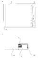
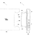
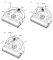
- FIG. 3 is a schematic plan view of a state in which a booklet unit and a voice recording / reproducing device are mounted.
- FIG. 3 is a schematic plan view of a state where a booklet part and a sound recording / playback apparatus are mounted and a page of the booklet part is opened.
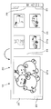
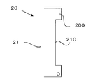
- the 2nd Embodiment of this invention is shown, The figure is a partial top view (1) for demonstrating the page specific part of a booklet part.
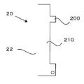
- the 2nd Embodiment of this invention is shown, The figure is a partial top view (2) for demonstrating the page specific part of a booklet part.
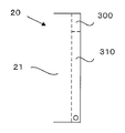
- the 3rd Embodiment of this invention is shown, The figure is a partial top view (1) for demonstrating the page specific part of a booklet part.
- the 3rd Embodiment of this invention is shown, The figure is a partial top view (2) for demonstrating the page specific part of a booklet part.
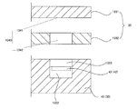
- the 4th Embodiment of this invention is shown, The figure is a partial cross section figure for demonstrating a mount and a seal
- FIG. 17 is a partial cross-sectional view corresponding to FIG. 16 in a state where a seal is attached.
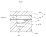
- the 5th Embodiment of this invention is shown, The figure is a partial cross section figure for demonstrating mount.
- FIG. 19 is a partial cross-sectional view for explaining a state where a printing unit is printed on a mount corresponding to FIG. 18.
- 6 shows a sixth embodiment of the present invention, which is a partial cross-sectional view for explaining a mount.
- the 7th Embodiment of this invention is shown, The figure is a partial cross section figure for demonstrating the detection part for booklet identification, and a terminal press part. It is a side view of the detection part for booklet identification, and the top view of a terminal press part.
- FIG. 22 is a partial cross-sectional view for explaining a state in which the terminal pressing portion is inserted into the insertion groove, corresponding to FIG. 21. It is a partial cross section for demonstrating the 8th Embodiment of this invention and demonstrating the state using the dot pattern in the booklet identification part. It is a figure (1) which shows a 9th embodiment of the present invention and explains a modification of an attachment piece. It is a figure (2) which shows a 9th embodiment of the present invention and explains a modification of an attachment piece. It is FIG. (3) which shows the 9th Embodiment of this invention and demonstrates the modification of an attachment piece.
- FIG. 29 is a plan view of an audio recording / reproducing apparatus having the touch detection unit according to the eleventh embodiment of the present invention, for explaining a modification of the touch detection unit of FIG. 28.
- the twelfth embodiment of the present invention is shown, which is a plan view for explaining the content output apparatus. It is a top view of the lower contact sheet
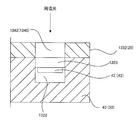
- reference numeral 10 denotes a voice book.
- the audio book 10 is roughly divided into the following parts.
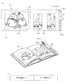
- the booklet unit 20 can hold an illustration 27a and a printed photograph 27b.
- illustration 27a and photograph 27b were illustrated, it is not limited to this, Message cards, postcards, clippings of books, magazines, etc. may be used.
- the booklet may be various publications such as a graphic book, a picture, a picture book printed with text, a picture book, and a photo book.
- the booklet unit 20 can identify a predetermined number of booklets, for example, a maximum of 64 booklet units 20 in the present embodiment.
- the number of booklet identification optical sensors 43 to be described later is six as the number of booklets in the booklet unit 20, 64 is exemplified by 2 to the 6th power, but is not limited thereto, and the booklet identification optical sensor 43 is not limited thereto. It is also possible to identify 65 or more booklet sections 20 by increasing the number of.
- the booklet unit 20 is provided with an overlapping portion at least partially overlapping with each other when the audio recording / reproducing apparatus 30 is mounted on the booklet unit 20. Further, although not shown, the booklet unit 20 and the voice recording / reproducing device 30 are detachable.
- the booklet section 20 is roughly composed of the following parts.
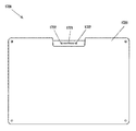
- Cover page 21 (2) Mount 22 A plurality of mounts 22 are provided, and in this embodiment, a total of 10 spread pages can be specified.
- the total number of pages that can be specified is limited to 10 pages. However, the number of pages may be two or more, and 3 to 9 pages, or by increasing the number of page-specific photosensors 43 described later, It is also possible to specify 11 pages or more.
- Binding section 24 The binding portion 24 is for forming one booklet portion 20 by binding the end portions of the front cover 21, the mount 22, and the back cover 23.
- the mounting portion 1020 is provided as a space having a predetermined shape after the last page of the booklet portion 20.
- the booklet unit 20 is provided with an overlapping portion at least partially overlapping with each other when the audio recording / reproducing apparatus 30 is mounted on the booklet unit 20. .
- the overlapping part is set on the free end side opposite to the binding part 24 of the booklet part 20 as shown in FIGS.
- the overlapping portion is set on the free end side of the booklet portion 20, the present invention is not limited to this, and the audio recording / playback device 30 is set on the binding portion 24 side, or is set on the upper edge side or the lower edge side. May be.
- a detection unit 40 (a booklet identification detection unit 41 and a page identification detection unit 42) using an optical sensor 43, which will be described later, is provided on the voice recording / playback device 30 side among the overlapping units.
- the booklet identifying unit 25 and the page specifying unit 26 are disposed on the booklet unit 20 side so as to cover the booklet identifying optical sensor 43 and the page identifying optical sensor.
- the “detection unit 40” on the voice recording / playback apparatus 30 side, and the “booklet identification unit 25” and “page identification unit 26” on the booklet unit 20 side will be described later.
- the optical sensor 43 is disposed on the voice recording / reproducing apparatus 30 side.
- the detection unit 40 (the booklet identification detection unit 41 and the page identification detection unit 42) uses an optical sensor 43 that does not have a light emitting unit and detects ambient light.
- the optical sensor 43 is configured by a photo sensor, an infrared sensor, or the like that detects ambient light without a light emitting unit.
- the following sensors can be used as the detection unit 40.
- Photosensor 43 such as a photo sensor or an infrared sensor of the present embodiment
- the optical sensor 43 includes a light emitting unit 43a using, for example, an IR-LED, and a light receiving unit 43b using, for example, a filter that passes only infrared rays in a predetermined wavelength region and a C-MOS sensor.
- a light emitting unit 43a using, for example, an IR-LED
- a light receiving unit 43b using, for example, a filter that passes only infrared rays in a predetermined wavelength region and a C-MOS sensor.
- the sound wave sensor emits an ultrasonic wave so that the reflection / absorption can be detected on the sensor side.
- the radio wave sensor emits radio waves, receives the reflected radio waves with an antenna, etc., detects the reflection / absorption, or transmits the emitted radio waves with an antenna, etc. And can be detected by information contained in received radio waves, whether received or not received.
- the book (4) and the above (3) can be classified as sensors other than light that receives sound waves and signals.
- the optical sensor 43 is disposed in the detection unit 40 of the audio recording / reproducing apparatus 30 as shown in FIG.
- the detection unit 40 is provided with a recess 1322 having an open upper surface, and the optical sensor 43 is disposed in the recess 1322.
- the open upper surface of the recess 1322 is covered with a cover 1323.
- the cover 1323 may be any one that can pass ambient light detected by a photo sensor or an infrared sensor. Note that the cover 1323 may be omitted.
- the booklet unit 20 includes a first page mount 1331 and a second page mount 1332. Note that the number of pages is not limited to two.
- a page specifying unit 1340 is provided at a detection position of the optical sensor 1310.
- the page specifying unit 1340 includes a non-translucent unit 1341 that blocks ambient light and a translucent unit 1342 that transmits ambient light.
- the translucent part 1342 may be formed from a cutout portion, or may be formed from a material through which ambient light can pass.
- the ambient light is blocked by the non-translucent portion 1341 of the first page mount 1331, Since the sensor 43 is not reached, it can be detected that the mount 1331 of the first page is closed.
- the detection unit 40 since the detection unit 40 is provided in a plane, the mount 1331 is overlapped on the mount 1332.
- the page detection unit 40 has a step difference for each page. Therefore, the mount 1331 directly overlaps the detection unit 40.
- the booklet identifying unit 25 is detected by the booklet identifying optical sensor 43, and transmits or blocks light incident on the optical sensor 43, thereby recording voice from a plurality of booklet units 20. Specific for mounting on the playback device 30, that is, for identifying one booklet unit 20.
- the booklet identification unit 25 is positioned corresponding to the optical sensor 43 for booklet identification.
- the page specifying unit 26 is detected by the optical sensor 43 for specifying the page. By transmitting or blocking the light incident on the optical sensor 43, how many pages of the attached booklet unit 20 are opened. It is for making it identify.
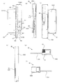
- the optical sensor 43 The principle of specifying a page is as described above (the optical sensor 43). (Voice recording / playback device 30 (voice playback device)) As shown in FIGS. 1 to 3, the audio recording / reproducing apparatus 30 is detachable from the booklet unit 20, stores audio data, and can reproduce the audio data.
- the audio recording / reproducing apparatus 30 is detachable from the booklet unit 20, stores audio data, and can reproduce the audio data.
- FIG. 7 shows a specific configuration of the voice recording / reproducing apparatus 30.
- 7A is a plan view of the audio recording / playback apparatus 30,
- FIG. 7B is a left side view
- FIG. 7C is a rear view
- FIG. 7D is a right side view
- FIG. 7E is a front view
- the voice recording / reproducing apparatus 30 has a recording function, but is not limited thereto, and may be a “voice reproducing apparatus” except for the recording function.
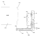
- the voice recording / reproducing apparatus 30 is roughly composed of an apparatus main body 1000 and an attachment piece 1010.
- the apparatus main body 1000 is provided with electric parts intensively. That is, the apparatus main body 1000 is roughly composed of a detection unit 40 and an operation unit 50.
- the audio data is stored in the audio data storage unit 62 of FIG. 8 to be described later on the assumption that the booklet unit 20 has a predetermined number of books and is associated with each booklet unit 20 having a predetermined number of books.
- the audio recording / reproducing apparatus 30 is provided with an overlapping portion that is at least partially overlapped with each other when mounted on the booklet portion 20.
- the overlapping part overlaps with the overlapping part (booklet identifying part 25 and page specifying part 26) on the booklet part 20, and a detecting part 40 described later is arranged.
- the voice recording / reproducing apparatus 30 is roughly divided into the following units.
- each part of the voice recording / reproducing apparatus 30 is not limited to the above (1) to (3).
- the detection unit 40 is for performing various types of detection of the booklet unit 20, and is arranged in an overlapping portion with the booklet unit 20.
- the detection unit 40 when viewed from the side surface on the left side in FIGS. 1 to 3, the detection unit 40 has a shape that increases stepwise from the lower side to the upper side of the booklet unit 20 as shown in FIG. 7. Is formed.
- each step of the stepped portion is set equal to the thickness of the front cover 21 and the mounts 22 and 22a of the booklet unit 20.
- the detection unit 40 is provided with the following units as shown in FIGS.
- each part of the detection part 40 is not limited to above-mentioned (1) and (2), For example, you may omit "(2) page specific detection part 42".
- the booklet identification detection unit 41 is for booklet identification that identifies one booklet unit 20 attached to the audio recording / reproducing apparatus 30 from among a plurality of booklet units 20.
- the booklet identification detection unit 41 is located at the lowest stepped portion of the detection unit 40, and a plurality of, for example, six booklet identification photosensors 43 are arranged at predetermined positions. ing.
- the six optical sensors 43 are arranged in a line in the vertical direction.
- a total of 64 types of booklet sections 20 can be identified by a combination of light incidents on the six optical sensors 43, including a case where no light is incident on the six optical sensors 43.
- optical sensors 43 Although six optical sensors 43 are provided, the present invention is not limited to this, and a plurality of optical sensors 43 is sufficient. For example, two, three, or seven or more may be provided.
- the optical sensors 43 are arranged in a line in the vertical direction, but the present invention is not limited to this.
- the optical sensors 43 may be arranged in a line in the horizontal direction or in multiple stages.
- the booklet identification detection unit 41 can be an inexpensive booklet identification detection unit 901 described later.
- the page specifying detection unit 42 is for specifying a page for specifying how many pages of the attached booklet unit 20 are open.
- the page specifying detection unit 42 is provided with a total of nine page specifying optical sensors 43 in the stepped portion of the detection unit 40.
- page specifying detection units 42 are provided, the present invention is not limited to this, and a plurality of page specifying units 42 is sufficient. For example, 2 to 8 or 10 or more may be provided.
- a relatively inexpensive sensor such as a photo sensor or an infrared sensor can be used.
- the optical sensor 43 which consists of the light emission part 43a and the light-receiving part 43b.
- the optical sensor 43 having the light receiving unit 43b it can be used indoors or outdoors without being influenced by ambient light.
- the irradiated surface can be closed with a plate made of plastic or the like through which infrared rays can pass, and the appearance and appearance can be improved.
- the operation unit 50 is for performing various operations of the voice recording / reproducing apparatus 30.
- the operation unit 50 includes the following units as shown in FIGS.
- each part of the operation unit 50 is not limited to the following (1) to (4).
- Speaker 51 The speaker 51 is located on the upper side of the operation unit 50, is connected to an electronic control device 60 described later, and reproduces audio data.
- the upper side of the operation part 50 was illustrated as a position of the speaker 51, it is not limited to this, You may arrange
- the microphone 52 is located on the lower side of the operation panel 53, is connected to an electronic control device 60 described later, and is used for recording voice.
- the lower side of the operation panel 53 was illustrated as a position of the microphone 52, it is not limited to this, You may arrange
- Operation panel 53 The operation panel 53 is arranged vertically below the speaker 51 and is connected to an electronic control device 60 to be described later for performing various operations.
- a switch group 70 including a power button, a pause button, a record button, a volume + button, a volume-button, a next play button, and an erase button is displayed, as well as various states
- a state display unit 80 including a first state display unit (3-color LED) and a second state display unit (3-color LED) is arranged.
- various functions such as language switching, quiz mode, ⁇ ⁇ , YES / NO answers may be provided.
- the upper side of the microphone 52 was illustrated as a position of the operation panel 53, it is not limited to this, You may arrange
- the operation panel 53 may be a touch panel instead of a button.
- Power supply unit 54 The power supply unit 54 is arranged vertically on the back side of the operation panel 53, is connected to an electronic control device 60 described later, and supplies power.
- the lower side of the operation panel 53 was illustrated as a position of the power supply part 54, it is not limited to this, You may arrange
- the power supply unit 54 uses a battery.
- the electronic control unit 60 is stored in the apparatus main body 1000 and controls various operations of the voice recording / reproducing apparatus 30.
- the electronic control unit 60 includes a CPU, a RAM, a ROM, and the like.
- a booklet identification detection unit 41 As shown in FIG. 8, a booklet identification detection unit 41, a page identification detection unit 42, a microphone 52, and a switch group 70 are connected to the input stage of the electronic control unit 60, respectively.
- a booklet identification detection unit 41, a page identification detection unit 42, a speaker 51, a status display unit 80, and an external connection unit 90 are connected to the output stage of the electronic control unit 60, respectively.
- the external connection unit 90 is for connecting the audio recording / playback apparatus 30 to the outside, and is provided with at least one or more of an earphone jack, a microphone jack, a USB jack, a card slot, etc. (not shown).
- a power supply unit 54 is connected to the electronic control device 60.
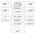
- the CPU reads the program to cause the electronic control unit 60 to function as the following units as shown in FIG.
- each part of the electronic control unit 60 is not limited to the following (1) to (4).
- the optical sensor control unit 61 controls the optical sensor 43 of the booklet identification detection unit 41 and the page identification detection unit 42.
- the optical sensor control unit 61 includes the following units.
- each part of the optical sensor control unit 61 is not limited to the following (1-1) to (1-2).
- the booklet identification control unit 61a identifies one booklet unit 20 attached to the audio recording / reproducing apparatus 30 based on a combination of sensor signals from a total of four booklet identifying optical sensors 43. Is.
- the booklet identification control unit 61 a reads out audio data corresponding to the attached booklet unit 20 from the audio data storage unit 62 and reproduces it via the audio reproduction control unit 64.
- the page specifying control unit 61b is for specifying the page number of the booklet unit 20 identified by the booklet identification control unit 61a based on the combination of sensor signals from the page specifying optical sensor 43. Is.
- Audio data storage unit 62 stores voice data.
- the audio data is stored in association with each booklet unit 20 having a predetermined number of books, assuming that the booklet unit 20 has a predetermined number of books.
- the audio data is stored in association with each page of the booklet unit 20.
- the audio data may be recorded, stored in advance, downloaded from the Internet, or recorded as a BGM by recording a song from a CD or the like.
- Voice recording control unit 63 The voice recording control unit 63 is for controlling voice recording, and the recorded voice data is stored in the voice data storage unit 62.
- Audio reproduction control unit 64 The audio reproduction control unit 64 is for reproducing audio data stored in the audio data storage unit 62.
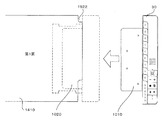
- the apparatus main body 1000 of the audio recording / reproducing apparatus 30 is unitized, and the mounting piece 1010 protruding from the apparatus main body 1000 is mounted on a mount 22 (see FIGS. 1 to 3) of the booklet unit 20 as shown in FIG.
- the apparatus main body 1000 can be easily attached to and detached from the booklet unit 20 by being inserted into or pulled out from the formed groove-shaped attachment unit 1020.
- the apparatus main body 1000 can be shared and used for a plurality of booklet sections 20.
- the mounting piece 1010 is formed on the apparatus main body 1000 and the groove-shaped mounting portion 1020 is formed on the mount 22 side.
- a groove-shaped attachment portion 1020 may be formed.
- the attaching part 1020 was made into groove shape, you may form not only in this but in a hole shape or a concave shape.
- the mounting portion 1020 may be manufactured separately from the mount 22 and fixed by screws, screws, adhesion, or the like.
- the mounting piece 1010 protrudes from the apparatus main body 1000 in a tongue shape.
- the attachment piece 1010 is inserted into a groove-like attachment portion 1020 provided on the mount 22 (see FIGS. 1 to 3) of the booklet portion 20 so that the apparatus main body 1000 can be attached to the booklet portion 20.
- the attachment piece 1010 and the attachment portion 1020 may be fixed so that the booklet portion 20 is not easily detached from the apparatus main body 1000, and the attachment piece 1010 is not easily removed due to frictional resistance or uneven engagement. It ’s enough.
- screws and screws may be used.
- the booklet unit 20 When the booklet unit 20 is attached to the audio recording / reproducing apparatus 30, the booklet unit 20 is identified. Thereafter, when the page is turned during the reproduction of the sound, the opened page is specified, and the sound data associated with the page is reproduced. Subsequently, when the page is turned, the audio data associated with the next page is reproduced in order.
- buttons on the operation panel with various functions such as language switching, quiz mode, answer of ⁇ ⁇ ⁇ , YES ⁇ NO, etc.
- the answer is reproduced and the answer can be judged by pressing a predetermined button.
- buttons such as numbers and alphabets may be provided and answered.
- These buttons are not limited to push buttons, but are capacitive, resistive (analog resistive), ultrasonic surface acoustic wave, acoustic pulse recognition, vibration detection (DST), and infrared shielding.
- a touch panel such as an electromagnetic induction method, a pressure sensitive sensor such as an LCD type with a built-in optical sensor, or the like may be used.
- a page specifying unit 1520 having a non-light transmitting portion 1521 and a light transmitting portion 1522 is formed on the mounts 1410 to 1510 of each page of the booklet portion 20.
- the non-translucent portion 1521 is formed by protruding the free end of the mount 1410 in a tab shape or a tongue shape.
- the translucent part 1522 is formed by cutting out a part of an end of the tab-shaped non-translucent part 1521, for example, a part of the upper end.
- the tab on page 10 is provided with one or more holes.
- the booklet is identified by this hole.
- a mount fixing mount for fixing the mounting portion 1020 for inserting the mounting piece 1010 of the audio recording / reproducing apparatus 30.
- the 10th page and the fixing mount may be bonded.
- the structure of the voice recording / reproducing apparatus 30 is as described above with reference to FIG.
- the attachment portion 1020 is provided as a space having a predetermined shape after the last page of the booklet portion.
- the material may also be molded to serve as a mounting portion.
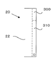
- a tab 200 is provided as a reflection part and a notch part 210 is provided as a non-reflection part.
- the tab 200 as a reflection portion of the present embodiment is not overlapped on the front and back pages.
- page specifying unit 26 has been described as an example, it can be used for the booklet identifying unit 25.
- the first feature of the present embodiment is that the optical sensor 43 detects a specific wavelength region of light, for example, infrared rays.
- an infrared reflecting layer 310 is provided as a reflecting portion that reflects or diffusely reflects at least infrared rays.
- the infrared non-reflective layer 300 is formed as a non-reflective portion that transmits or absorbs a specific wavelength region of light, for example, infrared rays.
- infrared rays were illustrated as a specific wavelength range of light, it is not limited to this.
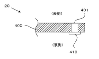
- page specifying unit 26 has been described as an example, it can also be used for the booklet identifying unit 25.
- the feature of the present embodiment is that a hole 401 penetrating the front and back surfaces of the mount 400 is formed as a non-reflective portion, and the back surface side of the hole 401 is closed with a seal 410. This is the point where the reflection part is formed.
- hole 401 was formed as a non-reflective part, it is not limited to this, You may form a notch.
- the seal 410 can reflect or diffusely reflect light that passes through the hole 401 and enters the optical sensor 43 (not shown).
- the optical sensor 43 (not shown) is connected to a specific wavelength region of light such as infrared rays.
- the seal 410 may reduce a specific wavelength region of light, for example, infrared light (including infrared light shielding).
- infrared rays were illustrated as a specific wavelength area
- sticker 410 was stuck from the back surface side of the base_sheet
- the above-mentioned seal may not be attached partially, but may be attached to the region of the edge of the mount 400 like a tape to hide the entire edge.
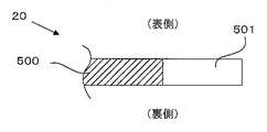
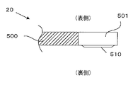
- the page specifying unit 26 has been described as an example, but the page specifying unit 26 may be used for the booklet identifying unit 25.
- the present embodiment is characterized in that a transparent portion 501 (including semi-transparent) is formed on a mount 500 to form a non-reflecting portion, which is incident on an optical sensor 43 (not shown).
- the reflection part is formed by printing the printing part 510 that reflects or diffusely reflects the light to the back side of the transparent part 501.
- the optical sensor 43 (not shown) is connected to a specific wavelength region of light such as infrared rays.
- a specific wavelength region of light such as infrared rays.
- infrared rays were illustrated as a specific wavelength range of light, it is not limited to this.
- the printing part 510 was printed from the back surface side of the base_sheet
- the page specifying unit 26 has been described as an example, it can also be used for the booklet identifying unit 25.
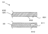
- the feature of the present embodiment is that the optical sensor 43 is used in the detection unit 40 in the first embodiment described above with reference to FIG. This is a point using 610.
- a plurality of booklet identifying microswitches 610 are placed at predetermined positions in an overlapping portion (detection unit 40, not shown) on the audio recording / playback device 30 side. It is arranged.
- each overlapping portion (booklet identifying unit 25 and page specifying unit 26, not shown) on the booklet unit 20 side is arranged at a position corresponding to the position of each microswitch 610.
- At least the same number of booklet identification portions 25 (not shown) that form either the pressing portion 601 that operates the actuator 611 of the microswitch 610 or the non-contact portion 602 that does not operate are arranged as the microswitch 610.
- the audio recording / reproducing apparatus 30 identifies the booklet unit 20 attached to the audio recording / reproducing apparatus 30 by a combination of operations of the actuator 611 of the micro switch 610, and The associated audio data can be played back.
- each page of the booklet unit 20 corresponds to the position of each micro switch 610 for page specification as shown in FIG.
- the page specifying unit 26 which is arranged at each of the positions and forms either the pressing unit 601 that operates the actuator 611 of each micro switch 610 or the non-contact unit 602 that does not operate the micro switch 610 for page specification. At least the same number is arranged.
- the voice recording / reproducing apparatus 30 has an opened page of the booklet unit 20 attached to the voice recording / reproducing apparatus 30 by a combination of the operations of the actuator 611 of the page specifying micro switch 610. And the audio data associated with the page can be reproduced.
- the voice recording / reproducing device 30 is provided in an embedded state, and the actuator 611 faces the booklet portion 20 side through a hole.
- the pressing portion 601 protrudes in a hemispherical shape from the back surface of the mount 600 of the booklet portion 20.
- the pressing unit 601 operates the microswitch 610 by pressing the actuator 611 through the hole when the mount 600 is brought close to the voice recording / reproducing apparatus 30.
- the micro switch 620 is deactivated from the operating state.
- the non-contact portion 602 is a portion without the pressing portion 601, and although not shown, when the mount 600 on which the pressing portion 601 is not formed is brought close to the voice recording / reproducing device 30, the micro switch 610 is turned on. Do not work.
- the voice recording / reproducing apparatus 30 performs booklet identification and page identification by another combination of operation / non-operation of the micro switch 610.
- press part 601 was formed in hemispherical shape, it is not limited to this, For example, you may form in a pin shape.
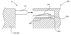
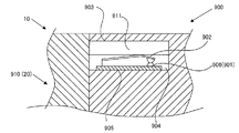
- a feature of the present embodiment is that the movable terminal 902 is used as the booklet identification detection unit 901 and the movable terminal 902 is pressed or non-pressed by the terminal pressing portion 911 protruding from the mount 910 of the booklet portion 20. The point is that the identification detector 901 is turned on and off.
- an inexpensive booklet identification detection unit 901 can be provided.
- the audio recording / reproducing apparatus 900 is provided with an insertion groove 903 into which the terminal pressing portion 911 of the mount 910 can be inserted, and a plurality of, for example, six movable terminals are provided behind the insertion groove 903. 902 is arranged separated by a predetermined interval.
- the present invention is not limited to this, and the recording function may be omitted, and the pre-recorded voice may be selectively reproduced by turning the page of the booklet unit 20.
- the present invention is not limited to this, and a plurality of terminal pressing portions 911 may be used, and two to five or seven or more may be located.
- the movable terminal 902 extends in a spring shape from the substrate 905, and a fixed contact 906 that contacts when the movable terminal 902 is lowered is provided on the upper surface of the substrate 905.
- the movable terminal 902 is pushed down by the terminal pressing portion 911 inserted into the insertion groove 903 and comes into contact with the fixed contact 906, so that the circuit constituting the detecting portion 901 is turned off. Switch to the on state.
- the terminal pressing portion 911 is pulled out from the insertion groove 903
- the movable terminal 902 is lifted by the spring force and separated from the fixed contact 906, so that the circuit constituting the detecting portion 901 is switched from on to off. .
- the substrate 905 having the movable terminal 902 is disposed in a recess 904 provided at the back of the insertion groove 903, and the movable terminal 902 enters the insertion groove 903 from the upper surface of the insertion groove 903. It is arranged to protrude.
- the terminal pressing portion 911 protrudes from the mount 910 of the booklet portion 20 in a tongue-like shape, and is provided with a notch portion 912 at a location where the movable terminal 902 is not pressed.
- the terminal pressing portion 911 is inserted into the insertion groove 903, the movable terminal 902 is not pressed and functions as a non-pressing portion, and the portion without the notching portion 912 functions as a press at a location where the notch 912 is present.
- the insertion groove 903 is formed in the audio reproduction device 900 and the movable terminal 902 is disposed in the back thereof, the present invention is not limited thereto.
- a fitting portion having an open upper surface into which the terminal pressing portion 911 of the mount 910 is fitted is formed, and the movable terminal 902 is disposed in the fitting portion.
- the movable terminal 902 can be pressed or non-pressed by placing the terminal pressing portion 911 in accordance with the fitting portion.
- the booklet identification unit 25 uses a dot pattern.
- the dot pattern is a kind of two-dimensional code and is an automatic recognition technology that inputs and outputs various information and programs. Specifically, it is disclosed in Japanese Patent No. 3706385, Japanese Patent No. 3858051, Japanese Patent No. 3771252, Japanese Patent No. 4833472, Japanese Patent No. 5344327, and the like. Of course, any dot pattern may be used.
- the booklet identification detection unit is provided with a sensor unit that captures a dot pattern, an irradiation device (such as an LED) that emits infrared light, and a decoding unit that decodes a code value from the captured dot pattern.
- a sensor unit that captures a dot pattern
- an irradiation device such as an LED
- a decoding unit that decodes a code value from the captured dot pattern.
- the dot pattern is coded with an index for identifying the booklet.
- the decoding unit analyzes the dot pattern and decodes it into a code value. And it identifies which booklet it is.
- the dot pattern is printed with ink that absorbs infrared rays. If a graphic or the like is printed over a dot pattern, it is printed with ink that does not absorb infrared rays.
- the dot pattern absorbs the infrared ray, and the infrared ray is reflected on the surface of the medium in a region other than the dot. For this reason, only the dot pattern is photographed black in the photographed image by the sensor unit.
- two LEDs are shown in the figure, one LED may be used. Further, a diffuser may be provided between the LED and the medium in order to uniformly illuminate the medium with light emitted from the LED.
- what is irradiated is not limited to infrared rays, but may be other electromagnetic waves such as ultraviolet rays and visible rays.
- the ink that prints the dot pattern is an ink that reacts with ultraviolet rays when irradiated with ultraviolet rays. In the case of irradiation with visible light, only the ink color used for the dots needs to be identified. Further, when the dot pattern is recognized with visible light, the irradiation device may be removed as long as the external light enters the structure.
- the sensor unit is arranged upward from the bottom, but a dot pattern printed on the upper surface of the medium may be photographed by arranging downward or obliquely downward from the top.
- the voice recording / reproducing apparatus 30 is provided with voice recognition means and has a voice recognition function.
- the user utters words (for example, “wedding album”) that specify the booklet toward the microphone 52.
- the voice recognition means analyzes the words, and the voice recording / playback device 30 specifies the booklet.
- the audio recording / reproducing apparatus 30 specifies that the booklet unit 20 is a wedding album.
- the ID may be uttered.
- an ID is assigned to each booklet in advance.
- the voice recognition means analyzes the ID, and the voice recording / reproducing apparatus 30 specifies the booklet.
- the ID is usually composed only of numbers and alphabets, and has an advantage that the accuracy of voice recognition is higher than that of various words.
- RFID In addition, not only RFID but other means may be used as long as an ID signal can be transmitted wirelessly.
- a wireless transmission device for transmitting signals is provided at a predetermined position of the booklet identification unit 25, and a plurality of (two or more) sensors for receiving signals are provided in the booklet identification detection unit 41. .
- a signal is transmitted, only the sensor at a position corresponding to the position of the signal detects the signal.
- the booklet is specified depending on which sensor detects the signal. That is, the booklet can be specified by changing the position and number of signals of the wireless transmission device.
- a transmission means for transmitting a signal wave is provided at a predetermined position of the booklet identification unit 25, and a sensor for receiving the signal wave is provided in the booklet identification detection unit 41.
- the original signal wave is transmitted from the transmitting means, the original signal wave is changed by at least one of reflection, transmission, attenuation, refraction, blocking, and absorption in the overlapping portion.
- the sensor receives the changed signal wave.
- a booklet can be specified by this change. According to this, the thickness of each page of the booklet unit 20 can also be recognized.
- the cause of the change in the signal wave is a change in frequency, amplitude, phase, coarse density, or noise.
- the transmitting means may transmit electromagnetic waves or sound waves (or both) instead of signal waves, and the sensor may receive electromagnetic waves or sound waves (or both) instead of signal waves.
- each page of the booklet unit 20 may be disposed between the transmission means and the sensor. If it does in this way, the original signal transmitted by the transmission means will change by being transmitted, attenuated, refracted, blocked or absorbed in a predetermined area of the page. This changed signal is received by the sensor.
- each page of the booklet unit 20 may be arranged so as to cover the transmission means and the sensor. If it does in this way, the original signal transmitted with the transmission means will be reflected or changed in the predetermined field of a page, and will change. This changed signal is received by the sensor.
- the booklet identification method is not limited to these, and any method may be used. Moreover, these methods can be used not only for identifying a booklet but also for specifying a page.
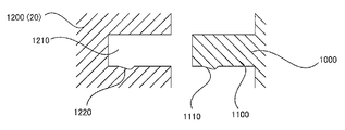
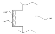
- the feature of this embodiment is that the mounting piece 1010 is deformed as described with reference to FIGS.
- a convex portion 1110 is provided on the lower surface of the mounting piece 1100.
- a plurality of, for example, three convex portions 1110 are provided apart from each other in the width direction of the mounting piece 1100.
- each convex portion 1110 is formed with a tapered surface that is inclined with respect to the insertion direction of the mounting piece 1100, thereby improving the insertability into the insertion groove 1210 and the operability when pulling out.
- the three convex parts 1110 were provided, it is not limited to this, You may provide one or two or four or more.
- the lower surface inside the insertion groove 1210 is provided with a plurality of, for example, three concave portions 1220 into which the three convex portions 1110 fit into each other when the mounting piece 1100 is inserted.
- the recess 1220 may be formed in a hole shape or a slit shape.
- the number of the concave portions 1220 is exemplified as three, the number is not limited to three as long as the number corresponds to the number of the convex portions 1110.
- the convex portion 1110 is formed on the lower surface of the mounting piece 1100 and the concave portion 1220 is formed on the lower surface inside the insertion groove 1210, it is sufficient that both portions face each other, and the formation position is not limited to the lower surface. Alternatively, it may be formed on a side surface or a plurality of surfaces.
- the feature of this embodiment is that the apparatus main body 1000 described above with reference to FIG. 7 is provided with a touch detection unit 1620 so that content corresponding to the touch position, for example, audio can be reproduced.
- the booklet identification detection unit 41 detects whether the booklet unit 1400 attached to the apparatus main body 1000 is detected, and the page specification detection unit 42 detects the number of pages of the opened mounts 1410 to 1510. In addition, by touching the touch detection unit 1620, sound corresponding to the opened page can be reproduced.
- quiz was taken as an example, it is not limited to it.
- the sound is played back when triggered by the touch.
- the present invention is not limited to this, and after touching, the sound or music may be recorded, and the recorded sound may be played back by touching the same position. .
- a protruding piece 1621 bent in an L shape is provided on the lower side of the apparatus main body 1000, and a printing unit 1623 printed with characters, pictures and the like indicating the touch position is provided on the surface thereof.
- an imaging device 1622 touch detection unit
- the imaging device 1622 has captured all of the “quiz”, “yes”, “no”, and “1” to “5” printing sections 1623. For example, when the “No” printing unit 1623 is touched with a finger, the “No” printing unit 1623 is hidden with the finger, and an image captured by the imaging device 1622 is displayed on the printing unit 1623 “1” to “5”.
- the touch detection unit 1620 can detect that “NO” is touched.
- the lower end portions of the mounts 1410 to 1510 in FIG. 28 are positioned along the upper surface of the protruding piece 1621 bent in an L shape, and may be in contact with the upper surface or may be positioned apart from each other. It may be. Further, the protruding piece 1621 is bent in an L shape so as to be along the lower end of the mounts 1410 to 1510.
- the present invention is not limited to this, but although not shown in the figure, the upper ends of the mounts 1410 to 1510 are formed.
- a touch detection unit 1620 may be provided in the apparatus main body 1000 so as to be positioned along the free end side of the mounts 1410 to 1510. Good.
- the feature of this embodiment is that the apparatus main body 1000 described above with reference to FIG. 7 is deformed.
- a touch sheet 1622 of a capacitive method or the like is used, and a touch detection unit is configured.
- the touch sheet 1622 is not limited to the capacitance method, but is a resistance film method (analog resistance film method), an ultrasonic surface acoustic wave method, an acoustic pulse recognition method, a vibration detection method (DST), an infrared light shielding method, an electromagnetic wave method, and the like.
- Other methods such as a guidance method and an LCD method with a built-in optical sensor may be used.
- touch detection means is not limited to the imaging device 1622 of FIG. 28 and the touch sheet 1622 of the present embodiment.
- transmitting means for transmitting electromagnetic waves (infrared rays, ultraviolet rays, visible light, etc.) or sound waves is provided on the base end side of the protruding piece 1621, and a sensor for detecting them is provided in the vicinity of the transmitting means.
- the printing unit 1623 is not touched at all, the entire printing unit reflects or absorbs electromagnetic waves or sound waves, and the sensor unit receives the reflected waves.
- electromagnetic waves or sound waves are reflected at the touch position or the covered position. .
- a reflected wave (first reflected wave) in a state where no touch or the like is performed is recorded in advance
- a reflected wave (second reflected wave) in a state where touch or the like is performed, By recognizing that the reflected wave of 1 is different, it is possible to detect which position on the medium is touched.
- the sensor is an infrared detection sensor.
- Each area of the printing unit (“quiz”, “yes”, “no”, “1", “2”, “3”, “4", and “5" in FIGS. 28 and 29) is printed with ink that absorbs infrared rays.
- a certain region for example, “Yes”
- they do not absorb infrared rays, so that infrared rays are reflected in that region, and the reflected wave is detected by the infrared detection sensor.
- it is detected that “Yes” is touched.
- a feature of this embodiment is that a dedicated sheet 800 as a medium can be attached to and detached from the content output apparatus 700.
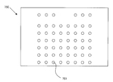
- the content output apparatus 700 is roughly provided with a base part 710 and a mount part 720.
- the base unit 710 includes a plurality of, for example, eight optical sensors 711 as medium identification means, and can identify a total of 256 dedicated sheets 800 each having 8 bits.
- the base unit 710 includes storage means for recording content and output means for outputting the content recorded in the storage means.
- the content is stored in association with a dedicated sheet 800 (medium) to be mounted and a graphic and / or text printed to clearly indicate the touch position on the medium.
- the base portion 710 has a transparent lid, and an overlapping portion 820 having an identification punch hole 821 to be described later can be sandwiched and fixed.
- optical sensor 711 was illustrated as a medium identification means, it is not limited to this.
- the mount portion 720 is in the form of a sheet and is connected and fixed to the base portion 710, and a plurality of, for example, 8 rows and 6 columns, for example, a total of 48 touch detection portions 721 are arranged on the surface thereof. ing.
- the touch detection unit 721 detects pressure or conductivity in a state where a sheet main body 810 (described later) of the dedicated sheet 800 (medium) is set on the mount unit 720, the touch detection unit 721 transmits the information to the base unit 710, and the base unit 710 The sound assigned to the dedicated sheet 800 (medium) identified by is reproduced.
- the touch detection unit 721 constitutes a touch position recognition unit that determines where a plurality of touch positions of a sheet body 810, which will be described later, of the dedicated sheet 800 (medium) is touched. It is not limited to the part 721.
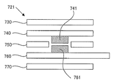
- a membrane switch is used for the touch detection unit 721 as shown in FIGS. As shown in FIG. 32, the membrane switch includes a top sheet 730, an upper contact sheet 740, a spacer 750, a lower contact sheet 760, and a back sheet 770.
- the upper contact sheet 740 is provided with a contact 741 so as to protrude toward the lower contact sheet 760 as shown in FIGS. 32 and 33.
- the contacts 741 are arranged in a matrix, and a plurality of contacts 741 are provided at the position of the touch detection unit 721.
- the contacts 741 arranged in a row are directly connected to each other by the conductive unit 742, and the conductive unit 742 is connected to the circuit of the base unit 710.
- the contact 741 and the conductive portion 742 are printed on a polyester film using a printing technique, for example.
- the lower contact sheet 760 is provided with a contact 761 so as to protrude toward the upper contact sheet 740 as shown in FIGS. 32 and 34.
- the contacts 761 are arranged in a matrix, and a plurality of the contacts 741 are provided at the position of the touch detection unit 721.
- the contacts 741 arranged in a column are directly connected to each other by the conductive unit 762, and the conductive unit 762 is connected to the circuit of the base unit 710. Has been.
- the spacer 750 is made of an insulating material, and as shown in FIGS. 32 and 35, a through hole 751 is formed in the insulating sheet.
- the through holes 751 are arranged in a matrix, and a plurality of through holes 751 are provided at the position of the touch detection unit 721.
- the contact 741 of the upper contact sheet 740 and the contact 761 of the lower contact sheet 760 are electrically connected to each other through the through-hole 751 when the surface sheet 730 is touched, that is, pressed.
- the contact 741 and the contact 761 immediately below are brought into conduction.
- a current is passed through one of the conductive portion 742 and the conductive portion 762, and it is detected that the touch detection portion 721 is touched by turning on and off the other.
- the coordinate value of the touch detection unit 721 that has been touched is specified by turning on / off the conductive units 762 in the vertical row while passing current sequentially through the conductive units 742 in the horizontal row.
- the membrane switch was used for the touch detection part 721, you may use not only this but touch panels, such as a pressure sensor and an electrostatic capacitance.
- the dedicated sheet 800 forms a medium on which graphics, photographs, and texts are printed, and is configured in a sheet shape overlapping the content output device 700 as shown in FIG.
- the dedicated sheet 800 includes a sheet body 810 that overlaps the mount portion 720 and an overlap portion 820 that overlaps the base portion 710.
- buttons written as “alphabet”, “English word”, “Japanese”, “quiz”, “yes”, “no”, alphabet “a” ”To“ z ”and numbers“ 0 ”to“ 10 ” are printed. Note that graphics, photos, and text are not limited to this embodiment.
- the overlapping portion 820 is provided with a punching hole 821 for identification.
- the identification punch holes 821 are positioned corresponding to the positions of the eight optical sensors 711, and the identification information of the medium of the dedicated sheet 800 is recorded by providing or not providing punch holes.
- the dedicated sheet 800 can identify up to 256 sheets, and the user can enjoy various contents by exchanging the dedicated sheet 800. (Thirteenth embodiment shown in FIGS. 36 to 37) Next, a thirteenth embodiment will be described with reference to FIGS.
- the feature of the present embodiment is a modification of the twelfth embodiment described above with reference to FIGS. 30 to 35.
- a base portion 1710 and a mount portion This is a point where uneven portions 1712 and 1722 for positioning are provided in the overlapping portion with 1720.
- the positioning of the base portion 1710 and the mount portion 1720 can be performed simply and accurately in a short time, and the reliability as a product of the audio recording / reproducing apparatus 1700 is improved. be able to.
- the audio recording / reproducing apparatus 1700 includes a base portion 1710 shown in FIG. 36A and a mount portion 1720 shown in FIG. 37, and the mount portion 1720 can be used by being exchanged for various types. It has become.
- the base portion 1710 is provided with a mount identifying portion 1711, and on both sides thereof, one of positioning uneven portions, for example, a positioning projection 1712 which is a convex portion is provided.
- a positioning projection 1712 which is a convex portion is provided.
- a plurality of positioning protrusions 1712 for example, a pair of left and right, are provided, the present invention is not limited to this, and three or more positioning protrusions 1712 may be provided.
- a cover portion 1713 that can be opened and closed is provided above the mount identifying portion 1711 and the positioning projection 1712.
- a carrying handle portion 1714 is provided on the upper side of the base portion 1710.
- the mount identifying unit 1711 includes eight optical sensors, but is not limited to eight, and is not limited to optical sensors.
- the mount portion 1720 is provided with a touch detection portion, and a detected portion 1721 that can be detected by the mount identification portion 1711 is provided at an overlapping portion with the base portion 1710, and positioning uneven portions are provided on both sides thereof.
- a positioning hole 1722 which is, for example, a recess is provided.
- the detected part 1721 is composed of holes, it is not limited to this.
- positioning protrusions 1712 fit into the positioning holes 1722, respectively.
- a plurality of positioning holes 1722 for example, the same number of left and right pairs as the positioning protrusions 1712 are provided.
- the present invention is not limited to this, and three or more positioning holes may be provided.
- the positioning hole 1722 which is a recessed part was provided in the mount part 1720 side
- the positioning protrusion 1712 which was a convex part was provided in the base part 1710
- a recess may be provided on the base portion 1710 side.
- a pressure sensor may be used, a membrane switch may be used as shown in FIGS. 32 to 35, or a capacitive type touch sheet may be used. May be.
- the base portion 1710 is connected to an electronic information device such as a personal computer (PC) by a wired or wireless connection via a connection cable such as a USB cable, and the mount portion 1720 is used as a keyboard. Also good.
- PC personal computer
- the base unit 1710 can be used by replacing the mount unit 1720, and the replaced mount unit 1720 can be identified by the mount identifying unit 1711. In addition, it is sufficient that the base unit 1710 is provided with switches such as a power supply and a volume that are common to a plurality of types of mount units 1720, but these switches may be omitted although not shown.
- the base unit 1710 has a voice recording / playback function, but voice recording can be stored in association with the touch position of the touch detection unit and the recorded voice data. Of course, voice recording may be omitted from the base portion 1710 and only the voice playback function may be provided. Furthermore, as described above, when the base unit 1710 is connected to a PC or the like, one or both of the voice recording function and the voice reproduction function may be omitted.
- the feature of the present embodiment is a modification of the twelfth embodiment described above with reference to FIGS. 30 to 35. As shown in FIGS. The camera 1750 and the lighting device 1751 are provided.
- FIG. 38 is a diagram for explaining such a voice recording / reproducing apparatus 1700.
- a camera 1750 and an illumination device 1751 are provided in the center of the handle portion 1714.
- FIG. 5B is a diagram showing a state where the handle portion 1714 is raised. In this manner, the handle portion 1714 can be raised up to 90 degrees. Of course, the rising angle is not limited to 90 degrees.
- FIG. 4C is a diagram showing a state where the camera is moved.
- the camera 1750 has a structure that can swing up and down. By adopting such a structure for the handle 1714 and the camera 1750, even if the medium to be mounted (mounting portion 1720) is not a sheet but a thick three-dimensional object, the mounting portion 1720 can be photographed under optimum conditions. Can do.
- the storage unit of the audio recording / reproducing apparatus 1700 images obtained by photographing a plurality of mounts 1720 in advance are stored.
- the user attaches the mount unit 1720 to the audio recording / reproducing apparatus 1700.
- the voice recording / reproducing apparatus 1700 captures the mount 1720 with the camera 1750 automatically or upon user operation when detecting that the mount 1720 is mounted.
- the medium identifying unit collates the image of the mount unit 1720 recorded in the storage unit with the photographed image, and identifies the mounted mount unit 1720 by finding a matching image.
- the image of the mount unit 1720 to be stored may be the entire mount unit 1720 or a part thereof.
- the feature points of the mount 1720 may be extracted.
- an image obtained by photographing only the feature points may be recorded in the storage unit, or a table in which an image obtained by photographing the entire image and the feature points are associated with each other may be recorded.
- the feature points can be set arbitrarily. For example, in the case of FIG. 39, the design of the boy printed on the “B Boy” area of the mount 1720 can be set.
- the mount unit 1720 is photographed by the camera, the medium identifying unit collates the feature point image recorded in the storage unit with the photographed image.
- the mount 1720 in FIG. 39A is photographed, the medium identifying unit searches for an image recorded in the storage unit.
- an image of “B Boy” is found, it is recognized that it matches the photographed image, and the mounted mount portion 1720 is specified.
- the image of the mount unit 1720 or the image of the feature point recorded in the storage unit can be taken by the camera 1750.
- the mount unit 1720 can print a graphic or text clearly indicating the touch position. It is assumed that “B” is touched with a finger as shown in FIG. Then, the portion “B” is hidden by the finger, and the image captured by the camera 1750 is a portion excluding “B”. By subtracting the image taken after the touch from the image taken before the touch, the image “B” can be acquired. As a result, it is recognized that the user touches the portion “B”, and the sound “Boy” corresponding to “B” is reproduced from the speaker of the sound recording / reproducing apparatus 1700.
- the mount unit 1720 may be a booklet-like medium instead of a sheet as illustrated. By using a booklet-shaped medium, more contents can be output.
- the mount 1720 can be touched with a predetermined object such as a touch pen in addition to a finger.
- a camera 1750 is installed, and the “booklet identification unit 25” and “page” on the booklet unit 20 side are installed. At least one part of the medium surface of the “specific part 26” can be photographed to identify the booklet part 20 and the page. Note that the “booklet identifying unit 25” and the “page specifying unit 26” do not have to be provided in an overlapping portion between the booklet unit 20 and the audio recording / reproducing device 30, and any place where the image is taken by the installed camera can be used. Good.
- the touch position can be acquired by an image recognition technique, and content corresponding to the touch position can be output.
- content corresponding to the touch position can be output.
- each photo may be stored and the content corresponding to each photo may be output by touching the photo.
- FIG. 40 is a modified example in which the camera 1750 is installed in the voice book apparatus main body 1000, and a case where a dot pattern is used will be described.
- the dot pattern is the same as that described in the above “eighth embodiment”.
- (A) is a plan view of the audio book 10 of the present embodiment
- (b) is a perspective view.
- a camera 1750 for reading a dot pattern is installed on the upper part of the apparatus main body 1000, and an irradiation apparatus 1751 is installed in the vicinity of the camera 1750.
- a dot pattern is printed on the upper right of each page of the booklet unit 20.
- the dot pattern of the booklet part 20 is visible in the figure for the sake of explanation, it is actually printed so as to be hardly visible. Note that the dot pattern may be superimposed and printed with a graphic.
- (C) is a diagram showing a format of a dot code encoded in a dot pattern.
- One dot pattern is encoded with a booklet identification code for identifying a booklet and a page specifying code for specifying a page.
- the booklet identification codes are the same regardless of the number of pages if they are the same booklet.
- the page identification code is assigned a different value for each page.
- the irradiation device 1751 irradiates the dot pattern with infrared rays.
- the camera 1750 captures the reflected light of the irradiation light applied to the booklet unit 20. Since the dot pattern is printed with ink that absorbs infrared rays, only a dot portion is photographed black in the photographed image.
- the decoding means analyzes the captured dot pattern image and decodes it into a code value (booklet identification code and page specific code). Thereby, the audio information / reproduction device 30 detects which page of which booklet is open, and outputs the corresponding audio from the speaker 51.
- the booklet unit 20 needs to be provided with two types of parts such as the booklet identification unit 25 and the page specification unit 26, and the audio information / reproduction device 30 with a booklet identification detection unit 41 and a page specification detection unit 42. Disappears. Thereby, the structure of the voice book can be simplified.
- what is irradiated is not limited to infrared rays, but may be other electromagnetic waves such as ultraviolet rays and visible rays.
- the ink that prints the dot pattern is an ink that reacts with ultraviolet rays when irradiated with ultraviolet rays.
- the irradiation device may be removed as long as the external light enters the structure.
- a camera-equipped terminal such as a smartphone, a mobile phone, or a tablet can be used in place of the audio information / reproduction device 1700.
- An image of the mount 1720 is recorded in advance on a camera-equipped terminal. This image may be taken by a camera-equipped terminal, or may be obtained by sending an e-mail taken from another camera. The user performs shooting with the camera-equipped terminal while touching the touch position of the mount 1720. Then, sound corresponding to the touch position is output from the speaker of the camera-equipped terminal.
- any audio recording / playback device or content output device outputs audio, but the present invention is not limited to this.
- Various contents such as text, images, video, multimedia, and Web can be output. Of course, two or more of these contents can be output simultaneously.
- the audio recording / playback device and the content output device include only the speaker, but may further include a display. Further, a display may be provided instead of the speaker.
- any audio recording / playback device or content output device can transmit content by connecting to other output devices or information devices such as mobile phones, smartphones, personal computers, etc. by wire or wirelessly.
- any audio recording / playback device and content output device can be provided with input means for inputting content and recording it in the storage means.
- the input means as described above, there is a microphone for recording sound, but a camera may be provided.
- a recording unit that records an image or video captured by the camera and converts the image or video into image or video data.
- the content may be received from the information device by connecting to the information device such as a personal computer by wire or wireless.
- a content output device configured to store the content in association with each medium, and at least a part of the content output device between the two when the medium is mounted.
- a content output apparatus comprising overlapping portions that overlap each other, mounting the medium, specifying the medium by the medium identification unit, and outputting the corresponding content recorded in the storage unit by the output unit .
- the medium is a booklet-shaped medium in which a plurality of pages are bound, and further includes page identification means for specifying the page of the medium, and the content is stored in association with the medium and each page of the medium.
- the page identification unit identifies the opened page of the medium, and the output unit displays the corresponding content recorded in the storage unit.
- a graphic and / or text that clearly indicates one or a plurality of touch positions is printed on the medium, and the content output device further recognizes where the touch position of the medium is touched. And the content is stored in association with the medium and the touch position of the medium, and the content output device is touched by the touch position recognition means when the medium is mounted.
- the content output apparatus according to (1) or (2), wherein the output unit outputs the corresponding content recorded in the storage unit by specifying
- the touch position recognizing means includes a camera, takes a photograph of a touched finger or a predetermined object and graphics and / or text clearly showing the one or more touch positions, and detects the touch position of the medium by image recognition.
- the touch position recognizing means includes a transmitting means for transmitting a predetermined electromagnetic wave or sound wave and a sensor for detecting the electromagnetic wave or the sound wave, and the electromagnetic wave or sound wave transmitted by the transmitting means is detected by a touched finger or a predetermined target.
- a transmitting means for transmitting a predetermined electromagnetic wave or sound wave and a sensor for detecting the electromagnetic wave or the sound wave, and the electromagnetic wave or sound wave transmitted by the transmitting means is detected by a touched finger or a predetermined target.
- the content output apparatus according to (3), wherein the position of one or a plurality of touch positions on the medium is determined by being different from each other.
- the electromagnetic wave is an infrared ray
- the sensor is an infrared detection sensor
- the graphic and / or text clearly indicating the one or more touch positions are printed with an ink that absorbs infrared rays, and the touched finger
- the content output apparatus according to (5), wherein a predetermined target object determines where the one or more touch positions of the medium are touched by reflecting infrared rays.
- the medium is a sheet or card-like medium on which graphics and / or texts clearly showing a plurality of touch positions are printed, and further, the one or more touch positions of the medium placed on the medium Touch position recognizing means for determining where the touch is made, the content is stored in association with the medium and the touch position of the medium, and the content output device is in a state where the medium is mounted.
- the content output apparatus according to (1), wherein the touch position is identified by the touch position recognition means, and the corresponding content recorded in the storage means is output by the output means.
- the page identification unit includes a plurality of sensors that detect predetermined electromagnetic waves or sound waves, and at least a part of the overlapping portion of each page of the medium is at least one of the plurality of sensors when the medium is closed.
- the predetermined electromagnetic wave or sound wave is disposed so as to cover one, the sensor does not detect the predetermined electromagnetic wave or sound wave of a predetermined amount or less, and the page of the medium is turned, whereby the overlap
- the content output device (2), wherein a sensor that is covered with a section detects the predetermined electromagnetic wave or sound wave to identify a page on which the medium is opened.
- the page identification means includes a plurality of sensors that detect predetermined electromagnetic waves or sound waves, and an overlapping portion of each page of the medium is disposed so as to cover the plurality of sensors in a state where the medium is closed. A state in which at least a part of the predetermined electromagnetic wave or sound wave is transmitted and the sensor detects a predetermined amount of the predetermined electromagnetic wave or sound wave, and the page of the medium is turned and covered with the overlapping portion.
- the content output device according to (2), wherein the sensor detects a predetermined amount of the predetermined electromagnetic wave or sound wave to identify a page on which the medium is opened.
- the predetermined electromagnetic wave is natural light incident from the periphery of the sensor or visible light emitted from a light source provided in the illumination device or the content output device. Content output device.
- the page identification unit includes a sensor, receives a signal transmitted from a wireless transmission device provided at a predetermined position for each page, and transmits the wireless transmission provided on the opened page by the sensor.
- the content output device according to (2) wherein an ID of a signal transmitted from the device and a characteristic of the signal are identified, the position is calculated, and the page is specified.
- the page identification unit includes at least two sensors, receives a signal transmitted from a wireless transmission device provided at a predetermined position for each page, and sets the page opened by the at least two sensors.
- the content output device according to (2) wherein an ID and a position of a signal transmitted from the wireless transmission device provided are identified, the position is calculated, and the page is specified.
- the medium identification unit includes a sensor that detects a predetermined electromagnetic wave or sound wave, and at least a part of the overlapping part of the medium is arranged to cover the plurality of sensors, and the first of the overlapping parts of the medium In the predetermined region, the predetermined electromagnetic wave or sound wave passes or transmits, the sensor detects the predetermined electromagnetic wave, and the predetermined electromagnetic wave or sound wave is blocked in the second predetermined region of the overlapping portion of the medium.
- the medium is identified by a combination of the sensors that have detected the electromagnetic waves or sound waves incident on the first and second predetermined areas because the sensor does not detect the predetermined electromagnetic waves or sound waves of a predetermined amount or less.
- the first predetermined region is provided with either a hole or a notch for allowing the predetermined electromagnetic wave or sound wave to pass therethrough, or a transmission medium through which the predetermined electromagnetic wave or sound wave is transmitted.
- the content output device as described in (15) above.
- the medium identifying means identifies the medium by voice recognition when a word or ID for identifying the medium is uttered toward a microphone provided as an input means.
- the medium identification unit includes a sensor, and receives and identifies an ID signal transmitted from a wireless transmission device included in the medium to identify the medium. Output device.
- the medium identification unit includes a plurality of sensors, receives a signal transmitted from a wireless transmission device provided at a predetermined position of the medium, and transmits the signal by at least two of the sensors.
- the medium identifying means includes a transmitting means for transmitting a signal wave and a sensor for receiving the signal wave at a predetermined position in the overlapping portion, and the original signal wave transmitted from the transmitting means overlaps the medium.
- the sensor receives the signal wave in which the original signal wave is changed by at least one of reflection, transmission, attenuation, refraction, blocking, and absorption at the part, and identifies the medium.
- the signal wave received by the sensor is a signal wave in which the original signal wave is changed due to at least one of a change in frequency, amplitude, phase, coarse density, or influence of noise.
- the transmitting means transmits at least one of electromagnetic waves or sound waves instead of signal waves, and the sensor receives at least one of electromagnetic waves or sound waves instead of signal waves.
- the content output device according to (20), characterized in that:
- At least a part of the overlapping part of the medium is arranged so as to be sandwiched between the transmitting unit and the sensor, and the original signal transmitted by the transmitting unit is in a predetermined region of the overlapping part of the medium.
- At least a part of the overlapping portion of the medium is disposed so as to cover the transmitting unit and the sensor, and the original signal transmitted by the transmitting unit is reflected or absorbed by a predetermined region of the overlapping portion of the medium.
- At least a part of the overlapping portion of the medium is arranged so that the transmitting means covers a plurality of the sensors provided in the vicinity, and a hole or a hole is formed in the first predetermined region of the overlapping portion of the medium.
- a notch is provided, and the original signal transmitted by the transmitting means passes through the hole or notch, and at least a part of the original signal is reflected in the second predetermined region of the overlapping portion of the medium.
- At least a part of the overlapping portion of the medium is disposed so as to be sandwiched between the plurality of sensors paired with the plurality of transmitting means, and a first predetermined region of the overlapping portion of the medium is defined.
- the plurality of sensors is formed by forming the original signal transmitted from the transmitting means with a material that does not reflect, and forming the second predetermined region of the overlapping portion of the medium with a material that reflects at least a part of the original signal.
- the content output apparatus according to (20) characterized in that the medium is identified by the combination of the presence or absence of reflected light in the first and second predetermined areas.
- At least a part of the overlapping portion of the medium is arranged so that the transmitting means that forms a pair covers a plurality of the sensors provided in the vicinity, and a first predetermined area of the overlapping portion of the medium is defined.
- the plurality of sensors is formed by forming the original signal transmitted from the transmitting means with a material that does not reflect, and forming the second predetermined region of the overlapping portion of the medium with a material that reflects at least a part of the original signal.
- the content output apparatus according to (20) characterized in that the medium is identified by the combination of the presence or absence of reflected light in the first and second predetermined areas.
- the first predetermined region of the overlapping portion of the medium is printed with an ink that absorbs infrared light, or is formed of a material that does not reflect infrared light
- the second predetermined region of the overlapping portion of the medium Is formed of a material that reflects or diffusely reflects infrared rays
- the transmitting means transmits infrared rays
- the sensor receives infrared rays
- the combination of the presence or absence of reflected light in the first and second predetermined regions is specified.
- the medium identification unit includes an image sensor that images at least a part of the medium and a decoding unit that decodes a code value from the captured dot pattern, and at least a part of the overlapping part of the medium Is printed with a dot pattern in which a code value for identifying the medium is defined, and the image sensor captures a part of the area on which the dot pattern is printed, and the dot pattern captured by the decoding unit.
- the content output device according to (1), wherein the medium is identified by analyzing the code and decoding the code value.
- the medium identification unit further includes an irradiation device that irradiates a predetermined electromagnetic wave to the partial region, and the image sensor images the dot pattern irradiated with the predetermined electromagnetic wave.
- the content output device according to (29).
- the page identification unit includes an image sensor that captures at least a part of the medium and a decoding unit that decodes a code value from the captured dot pattern.
- a dot pattern in which a code value specifying an open page of the medium is defined is printed, and the image sensor captures an image of an area where the dot pattern is printed, and the dot pattern captured by the decoding unit.
- the page identification unit further includes an irradiation device that irradiates a predetermined electromagnetic wave to the partial area, and the image sensor images the dot pattern irradiated with the predetermined electromagnetic wave.
- the content output device according to (31).
- the medium surface on which the dot pattern is printed is formed of a material that reflects the predetermined electromagnetic wave, and the dot pattern is printed using the ink that absorbs the predetermined electromagnetic wave (30) or (32)
- the content output device according to any one of the above.
- the medium identifying means is provided with a camera at a predetermined position where at least a part of the medium surface can be photographed, an image obtained by photographing the medium, and an image for identifying the medium registered in the storage means in advance.
- the medium identifying unit extracts a feature point of an image obtained by photographing the medium, collates the feature point with a feature point of an image that identifies the medium registered in the storage unit in advance, The content output device according to (35), wherein the medium is specified.
- a graphic and / or text that clearly indicates a touch position is printed on the medium, and the content output device further determines where the one or more touch positions of the medium are touched.
- the touch position recognizing means is photographed by the camera together with a touched finger or a predetermined object and graphics and / or text clearly showing the one or more touch positions, and is subjected to image processing to obtain one or more of the medium. It is determined where the plurality of touch positions are touched, the content is stored in association with the medium and the touch position of the medium, and the content output device is configured to touch the touch in a state where the medium is mounted.
- the touch position of the medium is specified by the position recognition means and the corresponding recorded in the storage means Above, wherein the outputting by the output means content (35)
- the content output apparatus according to any one of - (37).
- the touch position recognizing means is photographed before the touch from an image photographed by the camera together with the touched finger or the predetermined object and the graphic and / or text clearly indicating the one or more touch positions. Further, by subtracting the graphic and / or text images that clearly indicate the one or more touch positions and acquiring an image of only the touched finger or a predetermined object, the touch position of the medium is identified and stored.
- the content output apparatus according to (38), wherein the corresponding content recorded in the means is output by the output means.
- the content output device according to any one of (1) to (43), further including an input unit that inputs the content and records the content in the storage unit.
- a content output device comprising touch position recognition means for determining where the touch position is touched and output means for outputting content recorded in the storage means, wherein the medium identification means is the medium
- the medium identification means is the medium
- the content is stored in association with the medium and the touch position of the medium, and the content output device
- the touch position of the medium is specified by the touch position recognition means, and the corresponding content recorded in the storage means is output by the output means.
Landscapes
- Engineering & Computer Science (AREA)
- Theoretical Computer Science (AREA)
- Physics & Mathematics (AREA)
- General Physics & Mathematics (AREA)
- General Engineering & Computer Science (AREA)
- Human Computer Interaction (AREA)
- Business, Economics & Management (AREA)
- Educational Technology (AREA)
- Educational Administration (AREA)
- Computer Vision & Pattern Recognition (AREA)
- Health & Medical Sciences (AREA)
- Artificial Intelligence (AREA)
- Toxicology (AREA)
- General Health & Medical Sciences (AREA)
- Electromagnetism (AREA)
- User Interface Of Digital Computer (AREA)
Applications Claiming Priority (2)
| Application Number | Priority Date | Filing Date | Title |
|---|---|---|---|
| JP2014104776A JP6371115B2 (ja) | 2014-05-20 | 2014-05-20 | コンテンツ出力装置 |
| JP2014-104776 | 2014-05-20 |
Publications (1)
| Publication Number | Publication Date |
|---|---|
| WO2015178436A1 true WO2015178436A1 (ja) | 2015-11-26 |
Family
ID=54554100
Family Applications (1)
| Application Number | Title | Priority Date | Filing Date |
|---|---|---|---|
| PCT/JP2015/064542 Ceased WO2015178436A1 (ja) | 2014-05-20 | 2015-05-20 | コンテンツ出力装置および媒体 |
Country Status (2)
| Country | Link |
|---|---|
| JP (1) | JP6371115B2 (enExample) |
| WO (1) | WO2015178436A1 (enExample) |
Cited By (1)
| Publication number | Priority date | Publication date | Assignee | Title |
|---|---|---|---|---|
| CN112653956A (zh) * | 2019-10-11 | 2021-04-13 | Oppo广东移动通信有限公司 | 耳机盒、耳机装置、移动终端及无线耳机的充电方法 |
Families Citing this family (2)
| Publication number | Priority date | Publication date | Assignee | Title |
|---|---|---|---|---|
| CN105336230B (zh) * | 2015-11-20 | 2019-08-27 | 利奥纸袋(1982)有限公司 | 一种可拆卸发声装置的电子发声书及其认书方法 |
| KR102829062B1 (ko) * | 2022-06-22 | 2025-07-04 | 주식회사 에이블랩 | Ir 센서를 이용한 전시물 구별 및 안내 장치 |
Citations (10)
| Publication number | Priority date | Publication date | Assignee | Title |
|---|---|---|---|---|
| JPS5660940A (en) * | 1979-10-24 | 1981-05-26 | Nec Corp | Console desk |
| JPS57743A (en) * | 1980-06-03 | 1982-01-05 | Iwatsu Electric Co Ltd | Switchboard device using plural mask sheets |
| JPS57137029U (enExample) * | 1981-02-23 | 1982-08-26 | ||
| JPH05137846A (ja) * | 1991-11-21 | 1993-06-01 | Sega Enterp Ltd | 電子ブツク読取方法及び装置 |
| JP2004302768A (ja) * | 2003-03-31 | 2004-10-28 | Fuji Photo Optical Co Ltd | 入出力装置 |
| JP2006326895A (ja) * | 2005-05-24 | 2006-12-07 | Nova:Kk | 絵を押すと声の出る学習カード |
| JP2009070066A (ja) * | 2007-09-12 | 2009-04-02 | Osaka Prefecture Univ | 文書および/または画像のデータベースへの登録方法およびその検索方法 |
| WO2011007783A1 (ja) * | 2009-07-13 | 2011-01-20 | Yoshida Kenji | ストリームドットパターン、ストリームドットパターンの形成方法、ストリームドットパターンを用いた情報入出力方法およびドットパターン |
| WO2011142051A1 (ja) * | 2010-05-10 | 2011-11-17 | 日本システムウエア株式会社 | マーカー検出システム、検出方法、プログラム及び該プログラムを格納したコンピュータ可読媒体 |
| JP2013052668A (ja) * | 2011-09-05 | 2013-03-21 | Toru Kamikado | 頁連動型入出力装置 |
-
2014
- 2014-05-20 JP JP2014104776A patent/JP6371115B2/ja not_active Expired - Fee Related
-
2015
- 2015-05-20 WO PCT/JP2015/064542 patent/WO2015178436A1/ja not_active Ceased
Patent Citations (10)
| Publication number | Priority date | Publication date | Assignee | Title |
|---|---|---|---|---|
| JPS5660940A (en) * | 1979-10-24 | 1981-05-26 | Nec Corp | Console desk |
| JPS57743A (en) * | 1980-06-03 | 1982-01-05 | Iwatsu Electric Co Ltd | Switchboard device using plural mask sheets |
| JPS57137029U (enExample) * | 1981-02-23 | 1982-08-26 | ||
| JPH05137846A (ja) * | 1991-11-21 | 1993-06-01 | Sega Enterp Ltd | 電子ブツク読取方法及び装置 |
| JP2004302768A (ja) * | 2003-03-31 | 2004-10-28 | Fuji Photo Optical Co Ltd | 入出力装置 |
| JP2006326895A (ja) * | 2005-05-24 | 2006-12-07 | Nova:Kk | 絵を押すと声の出る学習カード |
| JP2009070066A (ja) * | 2007-09-12 | 2009-04-02 | Osaka Prefecture Univ | 文書および/または画像のデータベースへの登録方法およびその検索方法 |
| WO2011007783A1 (ja) * | 2009-07-13 | 2011-01-20 | Yoshida Kenji | ストリームドットパターン、ストリームドットパターンの形成方法、ストリームドットパターンを用いた情報入出力方法およびドットパターン |
| WO2011142051A1 (ja) * | 2010-05-10 | 2011-11-17 | 日本システムウエア株式会社 | マーカー検出システム、検出方法、プログラム及び該プログラムを格納したコンピュータ可読媒体 |
| JP2013052668A (ja) * | 2011-09-05 | 2013-03-21 | Toru Kamikado | 頁連動型入出力装置 |
Cited By (1)
| Publication number | Priority date | Publication date | Assignee | Title |
|---|---|---|---|---|
| CN112653956A (zh) * | 2019-10-11 | 2021-04-13 | Oppo广东移动通信有限公司 | 耳机盒、耳机装置、移动终端及无线耳机的充电方法 |
Also Published As
| Publication number | Publication date |
|---|---|
| JP2015219842A (ja) | 2015-12-07 |
| JP6371115B2 (ja) | 2018-08-08 |
Similar Documents
| Publication | Publication Date | Title |
|---|---|---|
| CN102224484B (zh) | 手写输入输出系统、手写输入薄板、信息输入系统、信息输入辅助薄板 | |
| TW394879B (en) | Graphics processing system and its data input device | |
| US20060012944A1 (en) | Mechanically operable electrical device | |
| RU2673275C2 (ru) | Способ воспроизведения информации, способ ввода/вывода информации, устройство воспроизведения информации, портативное устройство ввода/вывода информации и электронная игрушка, в которой использован точечный растр | |
| CN103052979B (zh) | 用于阅读媒体的提升的系统 | |
| US6874683B2 (en) | User programmable smart card interface system for an image album | |
| US6915103B2 (en) | System for enhancing books with special paper | |
| CN102906677B (zh) | 手写输入板以及使用手写输入板的信息处理系统 | |
| US7121462B2 (en) | User programmable smart card interface system | |
| KR20120123732A (ko) | 오더 시스템 | |
| WO2008013761A2 (en) | Associating a region on a surface with a sound or with another region | |
| US20090280461A1 (en) | Interactive Book with Detection of Lifted Flaps | |
| US6814294B2 (en) | User configurable remote control | |
| JP6371115B2 (ja) | コンテンツ出力装置 | |
| TWI333637B (en) | Education learning controller | |
| US7081885B2 (en) | System for enhancing books | |
| RU2473966C2 (ru) | Способ воспроизведения информации, способ ввода/вывода информации, устройство воспроизведения информации, портативное устройство ввода/вывода информации и электронная игрушка, в которой использован точечный растр | |
| KR101157630B1 (ko) | 시청각 교육용 학습서 및 학습 키트 | |
| AU742974B2 (en) | A user programmable smart card interface system | |
| KR101271421B1 (ko) | 퍼즐 자동 인식을 통한 콘텐츠 제공 장치 | |
| KR20120051790A (ko) | 디지털 학습 어프리케이션과 디지털 학습 시스템 | |
| KR20020079239A (ko) | 학습기 | |
| CN213303345U (zh) | 一种儿童有声读物 | |
| US20160148517A1 (en) | Talking notebook with projection | |
| US20160147314A1 (en) | Talking notebook |
Legal Events
| Date | Code | Title | Description |
|---|---|---|---|
| 121 | Ep: the epo has been informed by wipo that ep was designated in this application |
Ref document number: 15796727 Country of ref document: EP Kind code of ref document: A1 |
|
| NENP | Non-entry into the national phase |
Ref country code: DE |
|
| 122 | Ep: pct application non-entry in european phase |
Ref document number: 15796727 Country of ref document: EP Kind code of ref document: A1 |