WO2015178389A1 - 燃焼器交換方法及びガスタービンプラント - Google Patents
燃焼器交換方法及びガスタービンプラント Download PDFInfo
- Publication number
- WO2015178389A1 WO2015178389A1 PCT/JP2015/064365 JP2015064365W WO2015178389A1 WO 2015178389 A1 WO2015178389 A1 WO 2015178389A1 JP 2015064365 W JP2015064365 W JP 2015064365W WO 2015178389 A1 WO2015178389 A1 WO 2015178389A1
- Authority
- WO
- WIPO (PCT)
- Prior art keywords
- combustor
- fuel supply
- fuel
- manifold
- gas turbine
- Prior art date
- Legal status (The legal status is an assumption and is not a legal conclusion. Google has not performed a legal analysis and makes no representation as to the accuracy of the status listed.)
- Ceased
Links
Images







Classifications
-
- F—MECHANICAL ENGINEERING; LIGHTING; HEATING; WEAPONS; BLASTING
- F23—COMBUSTION APPARATUS; COMBUSTION PROCESSES
- F23R—GENERATING COMBUSTION PRODUCTS OF HIGH PRESSURE OR HIGH VELOCITY, e.g. GAS-TURBINE COMBUSTION CHAMBERS
- F23R3/00—Continuous combustion chambers using liquid or gaseous fuel
- F23R3/28—Continuous combustion chambers using liquid or gaseous fuel characterised by the fuel supply
- F23R3/34—Feeding into different combustion zones
- F23R3/346—Feeding into different combustion zones for staged combustion
-
- F—MECHANICAL ENGINEERING; LIGHTING; HEATING; WEAPONS; BLASTING
- F02—COMBUSTION ENGINES; HOT-GAS OR COMBUSTION-PRODUCT ENGINE PLANTS
- F02C—GAS-TURBINE PLANTS; AIR INTAKES FOR JET-PROPULSION PLANTS; CONTROLLING FUEL SUPPLY IN AIR-BREATHING JET-PROPULSION PLANTS
- F02C7/00—Features, components parts, details or accessories, not provided for in, or of interest apart form groups F02C1/00 - F02C6/00; Air intakes for jet-propulsion plants
-
- F—MECHANICAL ENGINEERING; LIGHTING; HEATING; WEAPONS; BLASTING
- F02—COMBUSTION ENGINES; HOT-GAS OR COMBUSTION-PRODUCT ENGINE PLANTS
- F02C—GAS-TURBINE PLANTS; AIR INTAKES FOR JET-PROPULSION PLANTS; CONTROLLING FUEL SUPPLY IN AIR-BREATHING JET-PROPULSION PLANTS
- F02C7/00—Features, components parts, details or accessories, not provided for in, or of interest apart form groups F02C1/00 - F02C6/00; Air intakes for jet-propulsion plants
- F02C7/20—Mounting or supporting of plant; Accommodating heat expansion or creep
-
- F—MECHANICAL ENGINEERING; LIGHTING; HEATING; WEAPONS; BLASTING
- F02—COMBUSTION ENGINES; HOT-GAS OR COMBUSTION-PRODUCT ENGINE PLANTS
- F02C—GAS-TURBINE PLANTS; AIR INTAKES FOR JET-PROPULSION PLANTS; CONTROLLING FUEL SUPPLY IN AIR-BREATHING JET-PROPULSION PLANTS
- F02C7/00—Features, components parts, details or accessories, not provided for in, or of interest apart form groups F02C1/00 - F02C6/00; Air intakes for jet-propulsion plants
- F02C7/22—Fuel supply systems
- F02C7/222—Fuel flow conduits, e.g. manifolds
-
- F—MECHANICAL ENGINEERING; LIGHTING; HEATING; WEAPONS; BLASTING
- F02—COMBUSTION ENGINES; HOT-GAS OR COMBUSTION-PRODUCT ENGINE PLANTS
- F02C—GAS-TURBINE PLANTS; AIR INTAKES FOR JET-PROPULSION PLANTS; CONTROLLING FUEL SUPPLY IN AIR-BREATHING JET-PROPULSION PLANTS
- F02C7/00—Features, components parts, details or accessories, not provided for in, or of interest apart form groups F02C1/00 - F02C6/00; Air intakes for jet-propulsion plants
- F02C7/22—Fuel supply systems
- F02C7/228—Dividing fuel between various burners
-
- F—MECHANICAL ENGINEERING; LIGHTING; HEATING; WEAPONS; BLASTING
- F02—COMBUSTION ENGINES; HOT-GAS OR COMBUSTION-PRODUCT ENGINE PLANTS
- F02C—GAS-TURBINE PLANTS; AIR INTAKES FOR JET-PROPULSION PLANTS; CONTROLLING FUEL SUPPLY IN AIR-BREATHING JET-PROPULSION PLANTS
- F02C7/00—Features, components parts, details or accessories, not provided for in, or of interest apart form groups F02C1/00 - F02C6/00; Air intakes for jet-propulsion plants
- F02C7/22—Fuel supply systems
- F02C7/232—Fuel valves; Draining valves or systems
-
- F—MECHANICAL ENGINEERING; LIGHTING; HEATING; WEAPONS; BLASTING
- F02—COMBUSTION ENGINES; HOT-GAS OR COMBUSTION-PRODUCT ENGINE PLANTS
- F02C—GAS-TURBINE PLANTS; AIR INTAKES FOR JET-PROPULSION PLANTS; CONTROLLING FUEL SUPPLY IN AIR-BREATHING JET-PROPULSION PLANTS
- F02C9/00—Controlling gas-turbine plants; Controlling fuel supply in air- breathing jet-propulsion plants
- F02C9/26—Control of fuel supply
- F02C9/32—Control of fuel supply characterised by throttling of fuel
-
- F—MECHANICAL ENGINEERING; LIGHTING; HEATING; WEAPONS; BLASTING
- F23—COMBUSTION APPARATUS; COMBUSTION PROCESSES
- F23R—GENERATING COMBUSTION PRODUCTS OF HIGH PRESSURE OR HIGH VELOCITY, e.g. GAS-TURBINE COMBUSTION CHAMBERS
- F23R3/00—Continuous combustion chambers using liquid or gaseous fuel
- F23R3/28—Continuous combustion chambers using liquid or gaseous fuel characterised by the fuel supply
-
- F—MECHANICAL ENGINEERING; LIGHTING; HEATING; WEAPONS; BLASTING
- F23—COMBUSTION APPARATUS; COMBUSTION PROCESSES
- F23R—GENERATING COMBUSTION PRODUCTS OF HIGH PRESSURE OR HIGH VELOCITY, e.g. GAS-TURBINE COMBUSTION CHAMBERS
- F23R3/00—Continuous combustion chambers using liquid or gaseous fuel
- F23R3/42—Continuous combustion chambers using liquid or gaseous fuel characterised by the arrangement or form of the flame tubes or combustion chambers
- F23R3/60—Support structures; Attaching or mounting means
-
- F—MECHANICAL ENGINEERING; LIGHTING; HEATING; WEAPONS; BLASTING
- F05—INDEXING SCHEMES RELATING TO ENGINES OR PUMPS IN VARIOUS SUBCLASSES OF CLASSES F01-F04
- F05D—INDEXING SCHEME FOR ASPECTS RELATING TO NON-POSITIVE-DISPLACEMENT MACHINES OR ENGINES, GAS-TURBINES OR JET-PROPULSION PLANTS
- F05D2220/00—Application
- F05D2220/30—Application in turbines
- F05D2220/32—Application in turbines in gas turbines
-
- F—MECHANICAL ENGINEERING; LIGHTING; HEATING; WEAPONS; BLASTING
- F05—INDEXING SCHEMES RELATING TO ENGINES OR PUMPS IN VARIOUS SUBCLASSES OF CLASSES F01-F04
- F05D—INDEXING SCHEME FOR ASPECTS RELATING TO NON-POSITIVE-DISPLACEMENT MACHINES OR ENGINES, GAS-TURBINES OR JET-PROPULSION PLANTS
- F05D2230/00—Manufacture
- F05D2230/60—Assembly methods
-
- F—MECHANICAL ENGINEERING; LIGHTING; HEATING; WEAPONS; BLASTING
- F05—INDEXING SCHEMES RELATING TO ENGINES OR PUMPS IN VARIOUS SUBCLASSES OF CLASSES F01-F04
- F05D—INDEXING SCHEME FOR ASPECTS RELATING TO NON-POSITIVE-DISPLACEMENT MACHINES OR ENGINES, GAS-TURBINES OR JET-PROPULSION PLANTS
- F05D2230/00—Manufacture
- F05D2230/70—Disassembly methods
-
- F—MECHANICAL ENGINEERING; LIGHTING; HEATING; WEAPONS; BLASTING
- F05—INDEXING SCHEMES RELATING TO ENGINES OR PUMPS IN VARIOUS SUBCLASSES OF CLASSES F01-F04
- F05D—INDEXING SCHEME FOR ASPECTS RELATING TO NON-POSITIVE-DISPLACEMENT MACHINES OR ENGINES, GAS-TURBINES OR JET-PROPULSION PLANTS
- F05D2230/00—Manufacture
- F05D2230/80—Repairing, retrofitting or upgrading methods
-
- F—MECHANICAL ENGINEERING; LIGHTING; HEATING; WEAPONS; BLASTING
- F05—INDEXING SCHEMES RELATING TO ENGINES OR PUMPS IN VARIOUS SUBCLASSES OF CLASSES F01-F04
- F05D—INDEXING SCHEME FOR ASPECTS RELATING TO NON-POSITIVE-DISPLACEMENT MACHINES OR ENGINES, GAS-TURBINES OR JET-PROPULSION PLANTS
- F05D2240/00—Components
- F05D2240/35—Combustors or associated equipment
-
- F—MECHANICAL ENGINEERING; LIGHTING; HEATING; WEAPONS; BLASTING
- F23—COMBUSTION APPARATUS; COMBUSTION PROCESSES
- F23R—GENERATING COMBUSTION PRODUCTS OF HIGH PRESSURE OR HIGH VELOCITY, e.g. GAS-TURBINE COMBUSTION CHAMBERS
- F23R2900/00—Special features of, or arrangements for continuous combustion chambers; Combustion processes therefor
- F23R2900/00016—Retrofitting in general, e.g. to respect new regulations on pollution
-
- F—MECHANICAL ENGINEERING; LIGHTING; HEATING; WEAPONS; BLASTING
- F23—COMBUSTION APPARATUS; COMBUSTION PROCESSES
- F23R—GENERATING COMBUSTION PRODUCTS OF HIGH PRESSURE OR HIGH VELOCITY, e.g. GAS-TURBINE COMBUSTION CHAMBERS
- F23R2900/00—Special features of, or arrangements for continuous combustion chambers; Combustion processes therefor
- F23R2900/00017—Assembling combustion chamber liners or subparts
Definitions
- the present invention relates to a combustor exchanging method and a gas turbine plant for exchanging a combustor of a gas turbine in which compressed air and fuel are combusted to generate combustion gas.
- a general gas turbine is composed of a compressor, a combustor, and a turbine.
- the air taken in from the air intake port is compressed by the compressor to become high-temperature and high-pressure compressed air.
- the fuel is supplied to the compressed air and burned, so that the high-temperature and high-pressure is burned.
- the combustion gas (working fluid) is obtained, the turbine is driven by the combustion gas, and the generator connected to the turbine is driven.
- Patent Document 1 a plurality of main combustion burners are arranged so as to surround the periphery of a pilot combustion burner, a fuel supply system that supplies fuel to the pilot combustion burner, and a fuel that supplies fuel to the plurality of main combustion burners
- a gas turbine plant that supplies the fuel supply system is described.
- Patent Document 1 includes a plurality of fuel supply systems that supply fuel to a plurality of main combustion burners. Some gas turbines supply fuel from a top hat nozzle separately from a main nozzle and a pilot nozzle. A gas turbine including a top hat nozzle includes a fuel system that supplies fuel to the top hat nozzle.
- the gas turbine plant may replace the combustor.
- the combustor is operated with a different fuel supply system instead of the combustor operated with the same fuel supply system, the fuel supply system is also replaced, which increases the work and the cost.
- This invention solves the subject mentioned above, and aims at providing the combustor replacement
- the present invention provides a combustor replacement method for replacing a combustor in a gas turbine of a gas turbine plant having a combustor and a plurality of fuel supply systems for supplying fuel to the combustor.
- a first combustor connected to any one of the plurality of fuel supply systems and having a plurality of nozzle systems to which fuel is supplied from the connected fuel supply system, separated from the fuel supply system;
- the amount of fuel that can be supplied before and after replacement can be maintained. Thereby, the work required for replacement can be reduced and the cost can be reduced.
- the fuel supply system has a manifold and a branch pipe connecting the manifold and the nozzle system, and the connecting pipe connects the branch pipe and the branch pipe.
- the upstream connecting pipe is disposed in the vicinity of the manifold connection point. Therefore, combustion in the combustor after exchange can be stabilized more. Moreover, the existing piping on the upstream side can be used in a long state. That is, the existing piping can be reused as much as possible, and the length of the replacement piping can be shortened.
- the upstream connecting pipe it is preferable to have an on-off valve disposed in the upstream connecting pipe.
- the fuel supply can be controlled for each fuel supply system.
- the upstream connection pipe can be left as it is, and replacement is simplified, and the degree of freedom in control design is increased. can do.
- the fuel supply system has a regulating valve for regulating fuel supply on the upstream side of the manifold, and the upstream connecting pipe is disposed between the manifold and the regulating valve. Thereby, combustion in the combustor after exchange can be stabilized more.
- a gas turbine plant of the present invention includes a combustor having a nozzle system to which fuel is supplied, a plurality of fuel supply systems that supply the fuel to the combustor, and the same combustor.
- the fuel supply system connected to a nozzle system is connected, and a connecting pipe that connects the fuel supply system and the combustor is provided.
- a control device configured to control fuel supplied from the plurality of fuel supply systems; and a pressure adjusting valve and a flow rate adjusting valve installed in the fuel supply system, wherein the control device includes the pressures of the plurality of fuel supply systems. It is preferable that the regulating valve is controlled independently and the flow regulating valves of the plurality of fuel supply systems are controlled independently. Thereby, combustion in a combustor can be controlled appropriately.
- a control device configured to control fuel supplied from the plurality of fuel supply systems; and a pressure adjusting valve and a flow rate adjusting valve installed in the fuel supply system, wherein the control device includes the pressures of the plurality of fuel supply systems. It is preferable to control the regulating valves in conjunction with each other, and to control the flow regulating valves in a plurality of fuel supply systems in conjunction with each other. Thereby, combustion in a combustor can be controlled appropriately.
- the fuel supply system has a manifold and a branch pipe connecting the manifold and the nozzle system for each nozzle system, and the connecting pipe connects the branch pipe and the branch pipe. Is preferred. Thereby, existing facilities can be used effectively.
- an upstream connecting pipe that communicates with the fuel supply system and an on-off valve disposed in the upstream connecting pipe are provided upstream of the manifold connected to the same nozzle system.
- the fuel supply can be controlled for each fuel supply system.
- the upstream connection pipe can be left as it is, and replacement is simplified, and the degree of freedom in control design is increased. can do.
- the fuel supply system has one manifold connected to a plurality of the nozzle systems, and the connecting pipe is installed on the upstream side of the manifold.
- the combustor can be efficiently exchanged using the existing equipment.
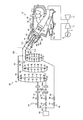
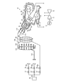
- FIG. 1 is a schematic configuration diagram showing a power generation system having a gas turbine plant according to the first embodiment.
- FIG. 2 is a schematic configuration diagram showing the structure of the fuel supply device and the combustor of the gas turbine plant shown in FIG.
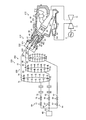
- FIG. 3 is a schematic configuration diagram showing a power generation system having a gas turbine plant before the combustor is replaced.
- FIG. 4 is a schematic configuration diagram showing the structure of the fuel supply device and the combustor of the gas turbine plant shown in FIG.
- FIG. 5 is a flowchart illustrating an example of a combustor replacement method.
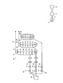
- FIG. 6 is a schematic configuration diagram showing a state during replacement of the combustor.
- FIG. 7 is a schematic configuration diagram showing a state during replacement of the combustor.
- FIG. 6 is a schematic configuration diagram showing a state during replacement of the combustor.
- FIG. 8 is a schematic configuration diagram showing a state during combustor replacement.
- FIG. 9 is an explanatory diagram for explaining an example of the operation of the gas turbine plant.
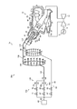
- FIG. 10 is a schematic configuration diagram showing a power generation system having a gas turbine plant according to the second embodiment.
- FIG. 11 is a schematic configuration diagram showing the structure of the fuel supply device and the combustor of the gas turbine plant shown in FIG.
- FIG. 12 is a flowchart for explaining another example of the combustor replacement method.
- FIG. 13 is a schematic configuration diagram showing a state during combustor replacement.
- FIG. 14 is a schematic configuration diagram showing a state during combustor replacement.
- FIG. 1 is a schematic configuration diagram showing a power generation system having a gas turbine plant according to the first embodiment.
- FIG. 2 is a schematic configuration diagram showing the structure of the fuel supply device and the combustor of the gas turbine plant shown in FIG.
- the power generation system 1 having the gas turbine plant of the present embodiment includes a gas turbine plant 2, a connecting shaft 6, and a generator 8.
- the connecting shaft 6 connects the rotating part of the gas turbine plant 2 and the generator 8.
- the generator 8 is rotated by transmitting the rotation of the gas turbine plant 2 via the connecting shaft 6 and generates power.
- the gas turbine plant 2 includes a gas turbine 10 and a fuel supply device 20.
- the gas turbine 10 includes a compressor 11, a plurality of combustors 12, and a turbine 13.
- the combustors 12 are arranged at predetermined intervals in the rotation direction of the gas turbine 10.
- the compressor 11 has an air intake port for taking in air, and inlet guide vanes (IGV: Inlet Guide Vane) are arranged in the compressor casing, and a plurality of stationary vanes and moving vanes are alternately arranged in the front-rear direction. It is installed.
- the combustor 12 is combustible by supplying fuel to the compressed air compressed by the compressor 11 and igniting it.
- a plurality of stationary blades and moving blades are alternately arranged in the front-rear direction in the turbine casing.
- the rotor rotary shaft
- the rotor 11 is fixed with the rotor blades of the compressor 11 and the turbine 13.
- a generator 8 is connected to the rotor of the gas turbine 10 via a connecting shaft 6.
- the air taken in from the air intake port of the compressor 11 passes through the inlet guide blade, the plurality of stationary blades, and the moving blade and is compressed to become high-temperature and high-pressure compressed air.
- a predetermined fuel is supplied to the compressed air in the combustor 12 and burned.
- the high-temperature and high-pressure combustion gas that is the working fluid generated by the combustor 12 passes through the plurality of stationary blades and the moving blades that constitute the turbine 13 to drive and rotate the rotor, and is connected to the rotor.
- the generator 8 is driven through the connecting shaft 6. Further, the energy of the exhaust gas (combustion gas) is converted into pressure by the exhaust diffuser in the exhaust chamber, decelerated, and then released to the atmosphere.
- FIG. 2 is a schematic configuration diagram showing the structure of the fuel supply device and the combustor of the gas turbine plant shown in FIG.
- the combustor 12 supports the combustor inner cylinder 42 of the combustor main body 40 at a predetermined interval in the circumferential direction inside the fuel / pressure chamber 41 and the turbine casing 43. .
- Compressed air Ain from the compressor 11 described above flows into the casing 48 covered with the turbine casing 43 through the diffuser portion 52 and the strut 54 at the compressor outlet.
- the strut 54 can rectify the compressed air Ain of the diffuser portion 52. Further, the compressed air Ain is taken into the air inflow port 40a of the combustor inner cylinder 42 from the passenger compartment 48 through the rectifying plate 50 formed of a perforated plate.
- a combustor tail cylinder 47 is connected to the rear end of the combustor inner cylinder 42.
- a pilot combustion burner 44 is disposed in the combustor inner cylinder 42 at the center of the inside.
- the combustor inner cylinder 42 is provided with a plurality of main combustion burners 45 on the inner peripheral surface of the combustor inner cylinder 42 so as to surround the pilot combustion burners 44 along the circumferential direction. That is, the pilot combustion burner 44 is disposed at the center inside the combustor inner cylinder 42, and a plurality of main combustion burners 45 are disposed around the pilot combustion burner 44.
- a bypass valve 49 is connected to the combustor tail cylinder 47. The bypass valve 49 may be omitted.
- the combustor 12 has a main nozzle system 112 that supplies fuel to the nozzles of the main combustion burner 45, and a pilot nozzle system 114 that supplies fuel to the nozzles of the pilot combustion burner 44.
- the main nozzle system 112 is a pipe that supplies fuel to the nozzle, and supplies the fuel supplied from the fuel supply device 20 to the main combustion burner 45.
- the pilot nozzle system 114 is a pipe that supplies fuel to the nozzle, and supplies the fuel supplied from the fuel supply device 20 to the pilot combustion burner 44.
- the main nozzle system 112 supplies fuel to the plurality of main combustion burners 45 of the combustor 12.
- the pilot nozzle system 114 supplies fuel to the plurality of pilot combustion burners 44 of the combustor 12.
- the gas turbine plant 2 of the present embodiment may use gas fuel or liquid fuel as fuel.
- the fuel supply device 20 includes a fuel tank 60, a fuel supply line 62, a first main fuel system 64, a second main fuel system 66, a pilot fuel system 68, a control device 70, and a first connection pipe 102. And the second connecting pipe 104.
- the fuel tank 60 is a storage unit that stores fuel, and sends the stored fuel toward the combustor 12.
- the fuel supply line 62 is a pipe, and supplies the fuel supplied from the fuel tank 60 to the first main fuel system 64, the second main fuel system 66, and the pilot fuel system 68. That is, the fuel supply device 20 supplies the same fuel to the first main fuel system 64, the second main fuel system 66, and the pilot fuel system 68.
- the first main fuel system 64 includes a first branch pipe 72, a first manifold 74, a plurality of first branch pipes 76, a first pressure adjustment valve 77, and a first flow rate adjustment valve 78.
- the first branch pipe 72 has one end connected to the fuel supply line 62 and the other end connected to the first manifold 74.
- a plurality of pipes are connected to the first branch pipe 72 to form one pipe line.
- the first manifold 74 is a ring-shaped pipe disposed so as to surround the outer periphery of the compressor 11.
- the first branch pipe 76 has one end connected to the first manifold 74 and the other end connected to the first connecting pipe 102.
- a plurality of first branch pipes 76 are provided for each combustor 12, and each is connected to a first connection pipe 102 corresponding to each combustor 12.
- the first pressure regulating valve 77 is disposed in the first branch pipe 72.
- the first pressure adjusting valve 77 adjusts the pressure of the fuel flowing through the first branch pipe 72 by adjusting the opening degree.
- the first flow rate adjustment valve 78 is disposed on the downstream side of the first pressure adjustment valve 77 of the first branch pipe 72.
- the first flow rate adjustment valve 78 adjusts the flow rate of the fuel flowing through the first branch pipe 72 by adjusting the opening degree.
- the second main fuel system 66 includes a second branch pipe 82, a second manifold 84, a plurality of second branch pipes 86, a second pressure adjustment valve 87, and a second flow rate adjustment valve 88.
- the second branch pipe 82 has one end connected to the fuel supply line 62 and the other end connected to the second manifold 84.
- the second branch pipe 82 is connected to a plurality of pipes to form one pipe line.
- the second manifold 84 is a ring-shaped pipe arranged so as to surround the outer periphery of the compressor 11.
- the second branch pipe 86 has one end connected to the second manifold 84 and the other end connected to the first connecting pipe 102.
- a plurality of second branch pipes 86 are provided for each combustor 12, and each is connected to a first connecting pipe 102 corresponding to each combustor 12.
- the second pressure regulating valve 87 is disposed in the second branch pipe 82.
- the second pressure adjustment valve 87 adjusts the pressure of the fuel flowing through the second branch pipe 82 by adjusting the opening degree.
- the second flow rate adjustment valve 88 is disposed on the downstream side of the second pressure adjustment valve 87 of the second branch pipe 82.
- the second flow rate adjusting valve 88 adjusts the flow rate of the fuel flowing through the second branch pipe 82 by adjusting the opening degree.
- the pilot fuel system 68 includes a pilot branch pipe 92, a pilot manifold 94, a plurality of pilot branch pipes 96, a pilot pressure adjustment valve 97, and a pilot flow rate adjustment valve 98.
- the pilot branch pipe 92 has one end connected to the fuel supply line 62 and the other end connected to the pilot manifold 94.
- the pilot manifold 94 is a ring-shaped pipe arranged so as to surround the outer periphery of the compressor 11.
- the pilot branch pipe 96 has one end connected to the pilot manifold 94 and the other end connected to the pilot nozzle system 114.
- a plurality of pilot branch pipes 96 are provided for each combustor 12, and each is connected to a pilot nozzle system 114 corresponding to each combustor 12.
- the pilot pressure adjustment valve 97 is disposed in the pilot branch pipe 92.
- the pilot pressure adjusting valve 97 adjusts the pressure of the fuel flowing through the pilot branch pipe 92 by adjusting the opening degree.
- the pilot flow rate adjusting valve 98 is disposed downstream of the pilot pressure adjusting valve 97 in the pilot branch pipe 92.
- the pilot flow rate adjustment valve 98 adjusts the flow rate of the fuel flowing through the pilot branch pipe 92 by adjusting the opening degree.
- the first connecting pipe 102 is arranged for each combustor 12 and is connected to the first branch pipe 76, the second branch pipe 86, and the main nozzle system 112 arranged for the same combustor 12.
- 76 is connected to the second branch pipe 86 and the main nozzle system 112.
- the first connecting pipe 102 is a pipe having one end branched into two, the branched end is connected to the first branch pipe 76 and the second branch pipe 86, and the other end is the main.
- the nozzle system 112 is connected.
- the first connecting pipe 102 supplies the fuel supplied from the first branch pipe 76 and the second branch pipe 86 to the main nozzle system 112.
- the second connecting pipe 104 connects the first branch pipe 72 and the second branch pipe 82. Specifically, one end of the second connecting pipe 104 is connected between the first flow control valve 78 of the first branch pipe 72 and the first manifold 74, and the other end is the second branch pipe. 82 is connected between the second flow control valve 88 and the second manifold 84.
- the second connecting pipe 104 allows fuel to flow between the first branch pipe 72 and the second branch pipe 82.
- the second connecting pipe 104 is provided with an on-off valve 104a. In this embodiment, the on-off valve 104a is provided, but the on-off valve 104a may not be provided.
- the fuel supply device 20 supplies the fuel in the fuel tank 60 from the first main fuel system 64 and the second main fuel system 66 to the main nozzle system 112.
- the fuel supply device 20 supplies the fuel in the fuel tank 60 from the pilot fuel system 68 to the pilot nozzle system 114.
- the control device 70 controls the fuel supplied from the fuel tank 60 to the combustor 12 by the fuel supply line 62, the first main fuel system 64, the second main fuel system 66, and the pilot fuel system 68.
- the control device 70 is connected to the first pressure regulating valve 77, the first flow regulating valve 78, the second pressure regulating valve 87, the second flow regulating valve 88, the pilot pressure regulating valve 97, and the pilot flow regulating valve 98, and opens the valve.
- the flow rate is controlled by controlling the degree.
- the control device 70 includes a microprocessor centered on a CPU (Central Processing Unit), a ROM (Read Only Memory) that stores processing programs in addition to the CPU, and a RAM (Random Access Memory) that temporarily stores data. ) And a storage device serving as storage means.
- a CPU Central Processing Unit
- ROM Read Only Memory
- RAM Random Access Memory
- FIG. 3 is a schematic configuration diagram showing a power generation system having a gas turbine plant before the combustor is replaced.
- FIG. 4 is a schematic configuration diagram showing the structure of the fuel supply device and the combustor of the gas turbine plant shown in FIG.
- the power generation system 200 shown in FIGS. 3 and 4 is the same as the power generation system 1 except that some of the combustor and the fuel supply device are not replaced. Parts that are the same as those of the power generation system 1, that is, parts that are not exchanged are denoted by the same reference numerals and description thereof is omitted.
- FIG. 3 and FIG. 4 includes a gas turbine plant 202, a connecting shaft 6, and a power generator 8.
- the gas turbine plant 202 includes a gas turbine 210 and a fuel supply device 220.
- the gas turbine 210 includes the compressor 11, a plurality of combustors 212, and the turbine 13.
- the combustors 212 are arranged at predetermined intervals in the rotation direction of the gas turbine 210.
- the combustor 212 includes a pilot combustion burner 44, a main combustion burner (first main combustion burner) 45, and a main combustion burner (second main combustion burner) 46 as combustion burners to which gas fuel is supplied. That is, the combustor 212 has two combustion burners as main combustion burners.
- the combustor 212 includes a plurality of main combustion burners (first main combustion burners) 45 and a plurality of main combustion burners (second main combustion burners) 46.
- the combustor 212 includes a first main nozzle system 221 that supplies fuel to the nozzles of the first main combustion burner 45, a second main nozzle system 222 that supplies fuel to the nozzles of the second main combustion burner 46, and a pilot combustion burner. And a pilot nozzle system 224 for supplying fuel to 44 nozzles.
- the fuel supply device 220 has the same structure as the fuel supply device 20 except that the fuel supply device 220 does not include the first connection pipe 102 and the second connection pipe 104.
- the first branch pipe 76 of the first main fuel system 64 is connected to the first main nozzle system 221
- the second branch pipe 86 of the second main fuel system 66 is connected to the second main nozzle system 222.
- the pilot branch pipe 96 of the pilot fuel system 68 is connected to the pilot nozzle system 224.
- three fuel supply systems supply fuel to each of the three nozzle systems of the combustor.
- FIG. 5 is a flowchart illustrating an example of a combustor replacement method.
- FIG. 6 and FIG. 8 are schematic configuration diagrams showing a state during combustor replacement. The main fuel supply system characteristic of the present embodiment will be described below, but the pilot fuel supply system is similarly attached and detached.
- step S12 first, the first main nozzle system 221 and the first branch pipe 76, and the second main nozzle system 222 and the second branch pipe 86 shown in FIG. 4 are separated (step S12). That is, each connection part is cut off. As a result, the combustor 212 is separated from the fuel supply device 220.
- step S14 the combustor 212 is removed (step S14).
- the connection between the combustor 212 and the compressor 11 and the connection between the combustor 212 and the turbine 13 are also disconnected, and the combustor 212 is disconnected from the gas turbine 210.
- the combustor 212 is removed from the power generation system 200 shown in FIG.
- step S16 the first branch pipe 76 and the second branch pipe 86 are connected by the first connection pipe 102 (step S16).
- step S18 a new combustor 12 is installed at the position where the combustor 212 was installed (step S18).
- step S16 and the process of step S18 may be reverse order, and may be parallel.
- step S20 the first connecting pipe 102 and the main nozzle system 112 of the combustor 12 are connected.
- fuel can be supplied from the fuel supply device 20 to the gas turbine 12.
- the compressor 11 and the turbine 13 are connected to the combustor 12 (step S22).
- compressed air is supplied from the compressor 11 to the combustor 12, and combustion gas can be supplied from the combustor 12 to the turbine 13.
- the first branch pipe 72 and the second branch pipe 82 are connected by the second connection pipe 104 (see step S24, FIG. 2). As a result, fuel can be distributed on the upstream side of the manifold.
- both the first main fuel system 64 and the second main fuel system 66 are main in the first connection pipe 102.
- fuel can be supplied to one main nozzle system 112 from two fuel supply systems.
- the combustor 212 has two main nozzle systems, and the combustor 12 has one main nozzle system.
- the combustor 12 is installed in the same gas turbine, the amount of fuel to be burned is the same. For this reason, the fluctuation
- the power generation system 1 can use the manifold as it is by connecting the first branch pipe 76 and the second branch pipe 86 with the first connecting pipe 102, and can reduce the number of parts to be replaced.
- the second connection pipe 104 connects the upstream side of the manifold, so that when only one fuel system is used, the other fuel system is connected. It is possible to suppress the accumulation of air. Thereby, stable combustion can be performed.
- the second connecting pipe (upstream connecting pipe) 104 is preferably arranged in the vicinity of the manifold connection point as in this embodiment. Moreover, it is preferable that the 2nd connection pipe 104 is arrange
- a regulating valve a flow regulating valve, a pressure regulating valve.
- the fuel supply device 20 can control the fuel supply for each fuel supply system by providing the on-off valve 104 a in the second connecting pipe 104. That is, the fuel supply device 20 opens the on-off valve 104a, operates in a state where the first main fuel system 64 and the second main fuel system 66 are connected by the second connecting pipe 104, closes the on-off valve 104a, The operation in a state where the first main fuel system 64 and the second main fuel system 66 are separated at the position of the second connecting pipe 104 can be performed. Thereby, it can open and close according to the system which supplies fuel.
- FIG. 9 is an explanatory diagram for explaining an example of the operation of the gas turbine plant.
- the control device 70 independently controls the first pressure regulating valve 77 of the first main fuel system 64 and the second pressure regulating valve 87 of the second main fuel system 66, so that the first main fuel system
- the 64 first flow rate adjusting valves 78 and the second flow rate adjusting valve 88 of the second main fuel system 66 are controlled independently.
- FIG. 9 is described as a case of controlling the flow rate, the pressure is the same.
- the control device 70 closes the second flow rate adjustment valve 88 and adjusts only the opening degree of the first flow rate adjustment valve 78. Thereafter, when the output increases even when the opening of the first flow rate adjustment valve 78 is fully open, the opening of the second flow rate adjustment valve 88 is adjusted. By using in this way, the valve of the object adjusted with each output can be made into one.
- the first pressure regulating valve 77 of the first main fuel system 64 and the second pressure regulating valve 87 of the second main fuel system 66 are controlled independently, and the first flow rate of the first main fuel system 64 is controlled.
- the adjustment valve 78 and the second flow rate adjustment valve 88 of the second main fuel system 66 are controlled independently, the first pressure adjustment valve 77 of the first main fuel system 64 and the second main fuel system are used.
- the second pressure regulating valve 87 of the first main fuel system 64 and the second flow regulating valve 88 of the second main fuel system 66 are controlled in conjunction with each other. May be. Thereby, two valves can be controlled as one valve, and even in this case, adjustment can be simplified. Further, when the valves are controlled in conjunction with each other, it is preferable to open and close the valves independently, that is, to open and close them at different times.
- the power generation system in which the combustor is replaced from the power generation system 200 (gas turbine plant 202) is not limited to this. That is, the structure for supplying fuel from a plurality of fuel supply systems to one nozzle system is not limited to the first embodiment.
- FIG. 10 is a schematic configuration diagram showing a power generation system having a gas turbine plant according to the second embodiment.
- FIG. 11 is a schematic configuration diagram showing the structure of the fuel supply device and the combustor of the gas turbine plant shown in FIG.
- the power generation system 1a shown in FIGS. 10 and 11 is the same as the power generation system 1 except for the structure of the fuel supply device 20a.
- the fuel supply device 20a of the gas turbine plant 2a of the power generation system 1a includes a first main fuel system 64a, a second main fuel system 66a, a pilot fuel system 68, a connection pipe 130, a main pipe 132, and a main manifold 134. And a branch pipe 136.
- the pilot fuel system 68 has the same structure as the pilot fuel system 68 of the fuel supply device 20.
- the first main fuel system 64a includes a first branch pipe 72a, a first pressure adjustment valve 77, and a first flow rate adjustment valve 78.
- the first branch pipe 72 a has one end connected to the fuel supply line 62 and the other end connected to the connecting pipe 130.
- the first pressure regulating valve 77 and the first flow regulating valve 78 are arranged in this order from the upstream in the first branch pipe 72a.
- the second main fuel system 66a includes a second branch pipe 82a, a second pressure adjustment valve 87, and a second flow rate adjustment valve 88.
- the second branch pipe 82 a has one end connected to the fuel supply line 62 and the other end connected to the connecting pipe 130.
- the second pressure regulating valve 87 and the second flow regulating valve 88 are arranged in this order from the upstream in the second branch pipe 82a.
- the connecting pipe 130 is connected to the first branch pipe 72a, the second branch pipe 82a, and the main pipe 132, and connects the first branch pipe 72a, the second branch pipe 82a, and the main pipe 132.
- the connecting pipe 130 is a pipe having one end branched into two, the branched end is connected to the first branch pipe 72a and the second branch pipe 82a, and the other end is the main pipe 132. Concatenate with The connecting pipe 130 supplies the fuel supplied from the first branch pipe 72 a and the second branch pipe 82 a to the main pipe 132.
- the main pipe 132 has one end connected to the connecting pipe 130 and the other end connected to the main manifold 134.
- the main pipe 132 supplies the fuel supplied from the connecting pipe 130 to the main manifold 134.
- the main manifold 134 is a ring-shaped pipe disposed so as to surround the outer periphery of the compressor 11.
- the plurality of branch pipes 136 are connected to the main manifold 134.
- the branch pipe 136 is disposed for each combustor 12 and supplies fuel from the main manifold 134 to the main nozzle system 112.
- the fuel supply device 20a joins the fuel supplied from the first main fuel system 64a and the second main fuel system 66a through the connecting pipe 130, passes through the main pipe 132, and burns in the main manifold 134 and the plurality of branch pipes 136. Each unit 12 is separated and supplied to each main nozzle system 112 from each branch pipe 136.
- FIG. 12 is a flowchart for explaining another example of the combustor replacement method.
- FIG.13 and FIG.14 is a schematic block diagram which respectively shows the state during combustor replacement
- step S32 the first branch pipe 72 and the first manifold 74, and the second branch pipe 82 and the second manifold 84 shown in FIG. 4 are separated (step S32). That is, each connection part is cut off. As a result, the first manifold 74 and the second manifold 84 are separated from the other parts of the fuel supply device 220. In addition, what is necessary is just to isolate
- the combustor 212 is removed (step S34).
- the connection between the combustor 212 and the compressor 11 and the connection between the combustor 212 and the turbine 13 are also disconnected, and the combustor 212 is disconnected from the gas turbine 210.
- the combustor 212 is removed, the combustor 212 and the first manifold 74 and the combustor 212 and the second manifold 84 are separated by separating and removing the branch pipes 76 and 86 from the combustor 212. Thereby, the removal operation
- work of the several combustor 212 can be performed separately.
- the first manifold 74 and the second manifold 84 are removed (step S36). As a result, the combustor 212, the first manifold 74, the second manifold 84, and the branch pipe 76 are removed from the power generation system 200 as shown in FIG. , 86 are removed.
- a new combustor 12 is installed (step S38), a new main manifold 134 is installed, and the combustor 12 and the main manifold 134 are connected (step S40). That is, the combustor 12 and the main manifold 134 are installed, and the main nozzle system 112 and the branch pipe 136 of the combustor 12 are connected. Then, the pilot nozzle system 114 and the pilot branch pipe 96 are connected. Note that a new combustor 12 may be installed after the main manifold 134 is installed. Thereby, as shown in FIG. 14, the combustor 12 and the main manifold 134 are installed in the predetermined position of a gas turbine plant.
- the compressor 11 and the turbine 13 are connected to the combustor 12 (step S42).
- compressed air is supplied from the compressor 11 to the combustor 12, and combustion gas can be supplied from the combustor 12 to the turbine 13.
- the first branch pipe 72a and the second branch pipe 82a are connected to the main manifold 134 (step S44).
- the first branch pipe 72 a, the second branch pipe 82 a, and the main pipe 132 are connected by the connection pipe 130.
- the fuel can be supplied to the main manifold 134 from the first branch pipe 72a and the second branch pipe 82a.
- the main pipe 132 has a larger flow area than the first branch pipe 72 a and the second branch pipe 82 a, and the main manifold 134 has a larger flow area than the first manifold 74 and the second manifold 84. Is preferred. Thereby, fuel can be supplied similarly.
- the combustor provided with two main nozzle systems is replaced with the combustor provided with one system has been described as a power plant having the replaced combustor. It is not limited to.
- the nozzle system integrated by exchanging the combustor may be another nozzle system.
- the fuel supply system may be connected in the same manner, or two pilot nozzle systems may be connected.
- the fuel supply system may be similarly connected.
- the fuel supply system may be similarly connected.
Landscapes
- Engineering & Computer Science (AREA)
- Chemical & Material Sciences (AREA)
- Combustion & Propulsion (AREA)
- Mechanical Engineering (AREA)
- General Engineering & Computer Science (AREA)
- Fuel Cell (AREA)
- Feeding And Controlling Fuel (AREA)
- Control Of Turbines (AREA)
Abstract
Description
図1は、第1実施形態に係るガスタービンプラントを有する発電システムを示す概略構成図である。図2は、図1に示すガスタービンプラントの燃料供給装置と燃焼器との構造を示す概略構成図である。本実施形態のガスタービンプラントを有する発電システム1は、図1に示すように、ガスタービンプラント2と、連結軸6と、発電機8と、を有する。連結軸6は、ガスタービンプラント2の回転部と発電機8とを連結する。発電機8は、連結軸6を介してガスタービンプラント2の回転が伝達されることで、回転され、発電する。
図10は、第2実施形態に係るガスタービンプラントを有する発電システムを示す概略構成図である。図11は、図10に示すガスタービンプラントの燃料供給装置と燃焼器との構造を示す概略構成図である。
2 ガスタービンプラント
6 連結軸
8 発電機
10 ガスタービン
11 圧縮機
12 燃焼器
13 タービン
20 燃料供給装置
40 燃焼器本体
40a 空気流入口
41 燃兼圧車室
42 燃焼器内筒
43 タービン車室
44 パイロット燃焼バーナ
45 メイン燃焼バーナ(第1メイン燃焼バーナ)
46 第2メイン燃焼バーナ
47 燃焼器尾筒
48 車室
49 バイパス弁
50 整流板
52 ディフューザ部
54 ストラット
60 燃料タンク
62 燃料供給ライン
64 第1メイン燃料系統
66 第2メイン燃料系統
68 パイロット燃料系統
70 制御装置
72 第1分岐管
74 第1マニホールド
76 第1枝管
77 第1圧力調整弁
78 第1流量調整弁
82 第2分岐管
84 第2マニホールド
86 第2枝管
87 第2圧力調整弁
88 第2流量調整弁
92 パイロット分岐管
94 パイロットマニホールド
96 パイロット枝管
97 パイロット圧力調整弁
98 パイロット流量調整弁
102 第1連結管
104 第2連結管
112 メインノズル系統
114、224 パイロットノズル系統
134 メインマニホールド
221 第1メインノズル系統
222 第2メインノズル系統
Claims (13)
- 燃焼器と、前記燃焼器に燃料を供給する複数の燃料供給系統と、を有するガスタービンプラントのガスタービンにおける燃焼器を交換する燃焼器交換方法であって、
複数の燃料供給系統のいずれかと接続され、接続された燃料供給系統から燃料が供給される複数のノズル系統を有する第1燃焼器を、前記燃料供給系統から分離し、ガスタービンプラントから取り外すステップと、
前記第1燃焼器よりもノズル系統が少ない第2燃焼器を前記ガスタービンプラントに取り付けるステップと、
前記第2燃焼器の同じノズル系統に接続される前記燃料供給系統を連結管で連通させ、前記燃料供給系統と前記第2燃焼器とを連結するステップと、を有することを特徴とする燃焼器交換方法。 - 前記燃料供給系統は、マニホールドと、前記マニホールドと前記ノズル系統とを接続させる枝管と、を有し、
前記連結管は、前記枝管と前記枝管を接続することを特徴とする請求項1に記載の燃焼器交換方法。 - 前記第2燃焼器の同じノズル系統に接続される前記マニホールドの上流側に、前記燃料供給系統を上流側連結管で連通させるステップをさらに有することを特徴とする請求項2に記載の燃焼器交換方法。
- 前記上流側連結管は、前記マニホールドの取り合い点の近傍に配置されていることを特徴とする請求項3に記載の燃焼器交換方法。
- 前記燃料供給系統は、前記マニホールドの上流側に燃料の供給を調整する調整弁を有し、
前記上流側連結管は、前記マニホールドと調整弁との間に配置されていることを特徴とする請求項3に記載の燃焼器交換方法。 - 前記上流側連結管に配置された開閉弁を有することを特徴とする請求項3から5のいずれか一項に記載の燃焼器交換方法。
- 前記第2燃焼器の同じノズル系統に接続される前記燃料供給系統のそれぞれのマニホールドを取り外すステップと、
前記第2燃焼器の同じノズル系統に接続される前記燃料供給系統に共通のマニホールドを設置するステップと、を有し、
前記連結管は、前記マニホールドの上流側に設置されることを特徴とする請求項1に記載の燃焼器交換方法。 - 燃料が供給されるノズル系統を有する燃焼器と、
前記燃焼器に前記燃料を供給する複数の燃料供給系統と、
前記燃焼器の同じノズル系統に接続される前記燃料供給系統を連通させ、前記燃料供給系統と前記燃焼器とを連結する連結管と、を有し、
ことを特徴とするガスタービンプラント。 - 複数の前記燃料供給系統から供給する燃料を制御する制御装置と、
前記燃料供給系統に設置された圧力調整弁と流量調整弁を備え、
前記制御装置は、複数の燃料供給系統の前記圧力調整弁を独立して制御し、複数の燃料供給系統の前記流量調整弁を独立して制御することを特徴とする請求項8に記載のガスタービンプラント。 - 複数の前記燃料供給系統から供給する燃料を制御する制御装置と、
前記燃料供給系統に設置された圧力調整弁と流量調整弁を備え、
前記制御装置は、複数の燃料供給系統の前記圧力調整弁を連動して制御し、複数の燃料供給系統の前記流量調整弁を連動して制御することを特徴とする請求項9に記載のガスタービンプラント。 - 前記燃料供給系統は、マニホールドと、前記マニホールドと前記ノズル系統とを接続させる枝管と、を前記ノズル系統毎に有し、
前記連結管は、前記枝管と前記枝管を接続することを特徴とする請求項9または10に記載のガスタービンプラント。 - 前記同じノズル系統に接続される前記マニホールドの上流側に、前記燃料供給系統を連通する上流側連結管と、
前記上流側連結管に配置された開閉弁を有することを特徴とする請求項11に記載のガスタービンプラント。 - 前記燃料供給系統は、複数の前記ノズル系統に接続される1つのマニホールドを有し、
前記連結管は、前記マニホールドの上流側に設置されることを特徴とする請求項9または10に記載のガスタービンプラント。
Priority Applications (4)
| Application Number | Priority Date | Filing Date | Title |
|---|---|---|---|
| KR1020167030356A KR101811169B1 (ko) | 2014-05-23 | 2015-05-19 | 연소기 교환 방법 및 가스 터빈 |
| US15/301,492 US10612783B2 (en) | 2014-05-23 | 2015-05-19 | Combustor replacement method and gas turbine plant |
| CN201580021674.2A CN106460665B (zh) | 2014-05-23 | 2015-05-19 | 燃烧器更换方法以及燃气涡轮成套设备 |
| DE112015002424.7T DE112015002424B4 (de) | 2014-05-23 | 2015-05-19 | Brennkammer-Austauschverfahren und Gasturbinenanlage |
Applications Claiming Priority (2)
| Application Number | Priority Date | Filing Date | Title |
|---|---|---|---|
| JP2014-107430 | 2014-05-23 | ||
| JP2014107430A JP6335645B2 (ja) | 2014-05-23 | 2014-05-23 | 燃焼器交換方法及びガスタービンプラント |
Publications (1)
| Publication Number | Publication Date |
|---|---|
| WO2015178389A1 true WO2015178389A1 (ja) | 2015-11-26 |
Family
ID=54554057
Family Applications (1)
| Application Number | Title | Priority Date | Filing Date |
|---|---|---|---|
| PCT/JP2015/064365 Ceased WO2015178389A1 (ja) | 2014-05-23 | 2015-05-19 | 燃焼器交換方法及びガスタービンプラント |
Country Status (6)
| Country | Link |
|---|---|
| US (1) | US10612783B2 (ja) |
| JP (1) | JP6335645B2 (ja) |
| KR (1) | KR101811169B1 (ja) |
| CN (1) | CN106460665B (ja) |
| DE (1) | DE112015002424B4 (ja) |
| WO (1) | WO2015178389A1 (ja) |
Cited By (2)
| Publication number | Priority date | Publication date | Assignee | Title |
|---|---|---|---|---|
| US11156164B2 (en) | 2019-05-21 | 2021-10-26 | General Electric Company | System and method for high frequency accoustic dampers with caps |
| US11174792B2 (en) | 2019-05-21 | 2021-11-16 | General Electric Company | System and method for high frequency acoustic dampers with baffles |
Families Citing this family (6)
| Publication number | Priority date | Publication date | Assignee | Title |
|---|---|---|---|---|
| US10012387B2 (en) * | 2014-12-05 | 2018-07-03 | General Electric Company | Fuel supply system for a gas turbine engine |
| US11092084B2 (en) * | 2016-05-26 | 2021-08-17 | General Electric Company | Fuel delivery system for a gas turbine engine |
| EP3412972B1 (en) * | 2017-06-09 | 2020-10-07 | Ansaldo Energia Switzerland AG | Gas turbine comprising a plurality of can-combustors |
| KR101985081B1 (ko) * | 2017-07-14 | 2019-05-31 | 두산중공업 주식회사 | 연소장치 및 이를 포함하는 가스터빈 |
| DE102018123785B4 (de) * | 2018-09-26 | 2023-07-27 | Deutsches Zentrum für Luft- und Raumfahrt e.V. | Verfahren zum Betreiben einer Gasturbinenanordnung und Gasturbinenanordnung |
| JP2023102929A (ja) * | 2022-01-13 | 2023-07-26 | 東芝エネルギーシステムズ株式会社 | ガスタービンシステム |
Citations (4)
| Publication number | Priority date | Publication date | Assignee | Title |
|---|---|---|---|---|
| JPH10196402A (ja) * | 1997-01-08 | 1998-07-28 | Toshiba Corp | ガスタービン燃焼器吊り装置およびその運用方法 |
| US20060016198A1 (en) * | 2004-07-23 | 2006-01-26 | Peter Stuttaford | Apparatus and method for providing an off-gas to a combustion system |
| JP2009243310A (ja) * | 2008-03-28 | 2009-10-22 | Mitsubishi Heavy Ind Ltd | 燃焼器尾筒案内治具及びガスタービンの燃焼器の取り外し方法、並びに取付方法 |
| JP2009270575A (ja) * | 2008-05-05 | 2009-11-19 | General Electric Co <Ge> | 一次マニホルド二元ガスタービン燃料システム |
Family Cites Families (20)
| Publication number | Priority date | Publication date | Assignee | Title |
|---|---|---|---|---|
| US2374239A (en) * | 1941-03-29 | 1945-04-24 | Sedille Marcel Henri Louis | Gas turbine installation |
| JP2877296B2 (ja) * | 1995-09-11 | 1999-03-31 | 三菱重工業株式会社 | ガスタービン燃焼器の取付、取外し装置 |
| GB2306155B (en) * | 1995-10-11 | 1997-11-19 | Toshiba Kk | Apparatus and method for disassembling and assembling gas turbine combuster |
| US5921075A (en) * | 1995-10-19 | 1999-07-13 | Mitsubishi Jukogyo Kabushiki Kaisha | Burner replacing system |
| JPH11117769A (ja) | 1997-10-21 | 1999-04-27 | Mitsubishi Heavy Ind Ltd | ガスタービン油焚燃焼器における燃料油制御装置 |
| US6125624A (en) * | 1998-04-17 | 2000-10-03 | Pratt & Whitney Canada Corp. | Anti-coking fuel injector purging device |
| JP2000097435A (ja) | 1998-09-25 | 2000-04-04 | Hitachi Ltd | ガスタービン燃焼器 |
| US6367239B1 (en) * | 1998-12-09 | 2002-04-09 | General Electric Company | Fuel delivery systems and method |
| US6227227B1 (en) * | 1999-06-18 | 2001-05-08 | Masconi Commerce Systems Inc. | Single meter blending fuel dispensing system |
| JP3970244B2 (ja) * | 2001-07-10 | 2007-09-05 | 三菱重工業株式会社 | 予混合ノズルおよび燃焼器並びにガスタービン |
| JP4015656B2 (ja) * | 2004-11-17 | 2007-11-28 | 三菱重工業株式会社 | ガスタービン燃焼器 |
| US7464555B2 (en) * | 2005-05-05 | 2008-12-16 | Siemens Energy, Inc. | Catalytic combustor for integrated gasification combined cycle power plant |
| US9080513B2 (en) * | 2007-10-31 | 2015-07-14 | General Electric Company | Method and apparatus for combusting syngas within a combustor |
| US8820087B2 (en) * | 2008-09-08 | 2014-09-02 | Siemens Energy, Inc. | Method and system for controlling fuel to a dual stage nozzle |
| JP5495687B2 (ja) * | 2009-09-16 | 2014-05-21 | 三菱重工業株式会社 | 燃焼器尾筒の着脱用治具及び燃焼器尾筒の組立方法 |
| EP2565399A1 (de) * | 2011-09-02 | 2013-03-06 | Siemens Aktiengesellschaft | Vorrichtung zur Montage bzw. Demontage eines Bauteils an bzw. in einer stationären Gasturbine und Verfahren zur Montage und Demontage von einem Bauteil einer stationären Gasturbine |
| US9243804B2 (en) * | 2011-10-24 | 2016-01-26 | General Electric Company | System for turbine combustor fuel mixing |
| US8973366B2 (en) | 2011-10-24 | 2015-03-10 | General Electric Company | Integrated fuel and water mixing assembly for use in conjunction with a combustor |
| US9127593B2 (en) * | 2012-11-07 | 2015-09-08 | Siemens Energy, Inc. | Modular drop-in combustor assembly for industrial gas turbine and method for installation |
| US9255522B2 (en) * | 2012-11-07 | 2016-02-09 | Siemens Energy, Inc. | Modular drop-in transition assembly for industrial gas turbine and method for installation |
-
2014
- 2014-05-23 JP JP2014107430A patent/JP6335645B2/ja active Active
-
2015
- 2015-05-19 WO PCT/JP2015/064365 patent/WO2015178389A1/ja not_active Ceased
- 2015-05-19 DE DE112015002424.7T patent/DE112015002424B4/de active Active
- 2015-05-19 US US15/301,492 patent/US10612783B2/en active Active
- 2015-05-19 KR KR1020167030356A patent/KR101811169B1/ko active Active
- 2015-05-19 CN CN201580021674.2A patent/CN106460665B/zh active Active
Patent Citations (4)
| Publication number | Priority date | Publication date | Assignee | Title |
|---|---|---|---|---|
| JPH10196402A (ja) * | 1997-01-08 | 1998-07-28 | Toshiba Corp | ガスタービン燃焼器吊り装置およびその運用方法 |
| US20060016198A1 (en) * | 2004-07-23 | 2006-01-26 | Peter Stuttaford | Apparatus and method for providing an off-gas to a combustion system |
| JP2009243310A (ja) * | 2008-03-28 | 2009-10-22 | Mitsubishi Heavy Ind Ltd | 燃焼器尾筒案内治具及びガスタービンの燃焼器の取り外し方法、並びに取付方法 |
| JP2009270575A (ja) * | 2008-05-05 | 2009-11-19 | General Electric Co <Ge> | 一次マニホルド二元ガスタービン燃料システム |
Cited By (2)
| Publication number | Priority date | Publication date | Assignee | Title |
|---|---|---|---|---|
| US11156164B2 (en) | 2019-05-21 | 2021-10-26 | General Electric Company | System and method for high frequency accoustic dampers with caps |
| US11174792B2 (en) | 2019-05-21 | 2021-11-16 | General Electric Company | System and method for high frequency acoustic dampers with baffles |
Also Published As
| Publication number | Publication date |
|---|---|
| JP2015222063A (ja) | 2015-12-10 |
| KR101811169B1 (ko) | 2017-12-20 |
| DE112015002424B4 (de) | 2022-07-07 |
| CN106460665B (zh) | 2018-01-30 |
| CN106460665A (zh) | 2017-02-22 |
| US20170030583A1 (en) | 2017-02-02 |
| DE112015002424T5 (de) | 2017-03-09 |
| KR20160140855A (ko) | 2016-12-07 |
| US10612783B2 (en) | 2020-04-07 |
| JP6335645B2 (ja) | 2018-05-30 |
Similar Documents
| Publication | Publication Date | Title |
|---|---|---|
| JP6335645B2 (ja) | 燃焼器交換方法及びガスタービンプラント | |
| JP6276520B2 (ja) | ガスタービン圧縮機入口加圧及び流れ制御システム | |
| CN103452673B (zh) | 具有空气流旁路的增压联合循环系统 | |
| KR101577608B1 (ko) | 가스 터빈 엔진 서지 제어를 위한 방법 및 장치 | |
| JP2007315398A (ja) | 不足周波数運転時における抽気の使用によるガスタービン運転の方法 | |
| JP4885199B2 (ja) | ガスタービン運転制御装置及び方法 | |
| US9822705B2 (en) | Power augmentation system for a gas turbine | |
| US20160273393A1 (en) | Power generation system having compressor creating excess air flow | |
| US10060316B2 (en) | Power generation system exhaust cooling | |
| US20170058784A1 (en) | System and method for maintaining emissions compliance while operating a gas turbine at turndown condition | |
| US20160273396A1 (en) | Power generation system having compressor creating excess air flow and heat exchanger therefor | |
| US9169782B2 (en) | Turbine to operate at part-load | |
| JP2016176466A (ja) | 余剰空気を作り出す圧縮機および補助圧縮機を備える発電システム | |
| US20170074171A1 (en) | Gas turbine plant and method of improving existing gas turbine plant | |
| EP3070300B1 (en) | Power generation system having compressor creating excess air flow and cooling fluid injection therefor | |
| JP6870970B2 (ja) | タービン抽出による蒸気発生システム | |
| JP2017110646A (ja) | 燃焼器ガス抽出により蒸気を発生する発電プラント | |
| US9932856B2 (en) | Cooling apparatus for turbomachinery with method of installation | |
| JP2016037966A (ja) | 入口抽気熱システムを含むターボ機械システム及び部分負荷でターボ機械を運転する方法 | |
| JP2017110649A (ja) | 排気ガスダンパおよび圧縮ガス供給源を介してガスタービン排気エネルギーを制御するためのシステムおよび方法 | |
| KR102632779B1 (ko) | 복합 사이클 발전소 시스템의 열회수 증기 발생기 내의 열 피로 및 열 응력 감소를 위한 바이패스 도관 | |
| EP3112610B1 (en) | System for discharging compressed air from a compressor |
Legal Events
| Date | Code | Title | Description |
|---|---|---|---|
| 121 | Ep: the epo has been informed by wipo that ep was designated in this application |
Ref document number: 15795727 Country of ref document: EP Kind code of ref document: A1 |
|
| WWE | Wipo information: entry into national phase |
Ref document number: 15301492 Country of ref document: US |
|
| ENP | Entry into the national phase |
Ref document number: 20167030356 Country of ref document: KR Kind code of ref document: A |
|
| WWE | Wipo information: entry into national phase |
Ref document number: 112015002424 Country of ref document: DE |
|
| 122 | Ep: pct application non-entry in european phase |
Ref document number: 15795727 Country of ref document: EP Kind code of ref document: A1 |