WO2015177942A1 - 無電極プラズマを加速するmpdスラスタ、及び、mpdスラスタを用いて無電極プラズマを加速する方法 - Google Patents
無電極プラズマを加速するmpdスラスタ、及び、mpdスラスタを用いて無電極プラズマを加速する方法 Download PDFInfo
- Publication number
- WO2015177942A1 WO2015177942A1 PCT/JP2014/072147 JP2014072147W WO2015177942A1 WO 2015177942 A1 WO2015177942 A1 WO 2015177942A1 JP 2014072147 W JP2014072147 W JP 2014072147W WO 2015177942 A1 WO2015177942 A1 WO 2015177942A1
- Authority
- WO
- WIPO (PCT)
- Prior art keywords
- electrodeless plasma
- cathode
- mpd thruster
- plasma
- mpd
- Prior art date
Links
Images


Classifications
-
- F—MECHANICAL ENGINEERING; LIGHTING; HEATING; WEAPONS; BLASTING
- F03—MACHINES OR ENGINES FOR LIQUIDS; WIND, SPRING, OR WEIGHT MOTORS; PRODUCING MECHANICAL POWER OR A REACTIVE PROPULSIVE THRUST, NOT OTHERWISE PROVIDED FOR
- F03H—PRODUCING A REACTIVE PROPULSIVE THRUST, NOT OTHERWISE PROVIDED FOR
- F03H1/00—Using plasma to produce a reactive propulsive thrust
- F03H1/0081—Electromagnetic plasma thrusters
-
- H—ELECTRICITY
- H01—ELECTRIC ELEMENTS
- H01J—ELECTRIC DISCHARGE TUBES OR DISCHARGE LAMPS
- H01J27/00—Ion beam tubes
- H01J27/02—Ion sources; Ion guns
- H01J27/16—Ion sources; Ion guns using high-frequency excitation, e.g. microwave excitation
-
- H—ELECTRICITY
- H05—ELECTRIC TECHNIQUES NOT OTHERWISE PROVIDED FOR
- H05H—PLASMA TECHNIQUE; PRODUCTION OF ACCELERATED ELECTRICALLY-CHARGED PARTICLES OR OF NEUTRONS; PRODUCTION OR ACCELERATION OF NEUTRAL MOLECULAR OR ATOMIC BEAMS
- H05H1/00—Generating plasma; Handling plasma
- H05H1/24—Generating plasma
- H05H1/46—Generating plasma using applied electromagnetic fields, e.g. high frequency or microwave energy
-
- H—ELECTRICITY
- H05—ELECTRIC TECHNIQUES NOT OTHERWISE PROVIDED FOR
- H05H—PLASMA TECHNIQUE; PRODUCTION OF ACCELERATED ELECTRICALLY-CHARGED PARTICLES OR OF NEUTRONS; PRODUCTION OR ACCELERATION OF NEUTRAL MOLECULAR OR ATOMIC BEAMS
- H05H1/00—Generating plasma; Handling plasma
- H05H1/54—Plasma accelerators
-
- H—ELECTRICITY
- H05—ELECTRIC TECHNIQUES NOT OTHERWISE PROVIDED FOR
- H05H—PLASMA TECHNIQUE; PRODUCTION OF ACCELERATED ELECTRICALLY-CHARGED PARTICLES OR OF NEUTRONS; PRODUCTION OR ACCELERATION OF NEUTRAL MOLECULAR OR ATOMIC BEAMS
- H05H1/00—Generating plasma; Handling plasma
- H05H1/24—Generating plasma
- H05H1/46—Generating plasma using applied electromagnetic fields, e.g. high frequency or microwave energy
- H05H1/4645—Radiofrequency discharges
- H05H1/4652—Radiofrequency discharges using inductive coupling means, e.g. coils
Definitions
- the present invention relates to an MPD thruster for accelerating an electrodeless plasma and a method for accelerating the electrodeless plasma using an MPD thruster.
- An MPD thruster Magnetic-Plasma-Dynamic thruster
- FIG. 1 shows an example of an MPD thruster.
- the exemplary MPD thruster generates plasma by ionizing the propellant (gas) by arc discharge. Then, a Lorentz force is generated by the current flowing between the anode arranged on the outer peripheral side of the thruster and the cathode arranged on the center side, and a magnetic field generated by the current (or a magnetic field applied in advance). . The generated plasma is accelerated by the Lorentz force.
- Patent Document 1 discloses an electric propulsion device that obtains thrust by discharging plasma formed by arc discharge from a nozzle.
- Patent Document 2 discloses an ion engine that selectively accelerates charged particles formed by discharge using a screen electrode and an acceleration electrode.
- the MPD thruster includes an electrodeless plasma generation device that generates electrodeless plasma from a propellant, an acceleration device that accelerates the electrodeless plasma, and a supply that supplies the generated electrodeless plasma to the acceleration device.
- the acceleration device includes a magnetic coil, a cathode, an anode, and a voltage application device that applies a voltage between the cathode and the anode.
- the supply path supplies the electrodeless plasma to a space between the cathode and the anode.
- the magnetic coil generates an axial magnetic field component along the direction of the central axis of the magnetic coil and a radial magnetic field component orthogonal to the central axis in the space.
- the voltage application device generates a current in the space.
- the electrodeless plasma supplied to the space accelerates the electrodeless plasma by a Lorentz force induced by the axial magnetic field component, the radial magnetic field component, and the current.
- the method of accelerating the electrodeless plasma in the present invention is a method of accelerating the electrodeless plasma using an MPD thruster.
- the method of accelerating the electrodeless plasma includes a step of supplying an electrodeless plasma to a space between a cathode and an anode to lower an electrical resistivity in the space, and a direction of a central axis of the MPD thruster in the space. Generating a radial magnetic field component perpendicular to the central axis, generating a current in the space, the axial magnetic field component and the radial magnetic field component, and the current And accelerating the electrodeless plasma by a Lorentz force induced by.
- the above configuration provides an MPD thruster that can suppress power supply, reduce electrode wear, and improve propulsion efficiency.
- FIG. 1 is a cross-sectional view schematically showing a configuration of a conventional MPD thruster.
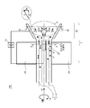
- FIG. 2A is a cross-sectional view schematically showing the configuration of the MPD thruster according to the first embodiment of the present invention.
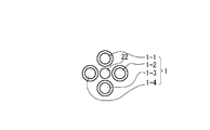
- 2B is a cross-sectional view taken along the line AA in FIG. 2A.
- 2C is a cross-sectional view taken along the line CC of FIG. 2A.
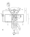
- FIG. 3A is a cross-sectional view schematically showing a configuration of an MPD thruster according to the second embodiment of the present invention.
- FIG. 3B is a cross-sectional view taken along the line AA in FIG. 3A.
- FIG. 4 is a perspective view of the MPD thruster according to the second embodiment, in which a part of the thruster is cut away.
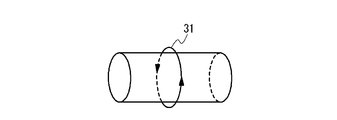
- FIG. 5A is a diagram illustrating a first example of an antenna (plasma generating antenna).
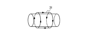
- FIG. 5B is a diagram illustrating a second example of an antenna (plasma generating antenna).
- FIG. 5C is a diagram illustrating a third example of the antenna (plasma generating antenna).
- FIG. 5D is a diagram illustrating a fourth example of the antenna (plasma generating antenna).
- FIG. 5E is a diagram illustrating a fifth example of an antenna (plasma generating antenna).
- FIG. 5A is a diagram illustrating a first example of an antenna (plasma generating antenna).
- FIG. 5B is a diagram illustrating a second example of an antenna (plasma generating antenna).
- FIG. 5C is a diagram illustrating
- FIG. 5F is a diagram illustrating a sixth example of the antenna (plasma generating antenna).
- FIG. 6 is a functional block diagram showing an example of an antenna operating device in the second embodiment of the present invention.
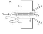
- FIG. 7 is a schematic diagram showing the positional relationship between the supply path, the cathode, and the anode and the positional relationship between the supply path, the antenna, and the magnetic coil in the embodiment of the present invention.
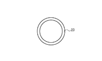
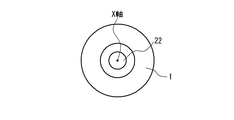
- FIG. 8 is a cross-sectional view showing a modified example of the supply path in the embodiment of the present invention, and is a cross-sectional view perpendicular to the X axis.
- the coordinate system is defined with reference to FIGS. 2A and 3A.
- the X direction is the front-rear direction of the MPD thrusters 100, 200, and the + X direction means the rear direction of the MPD thrusters 100, 200, that is, the nozzle side direction.
- the ⁇ direction is the rotation direction around the X axis, which is the central axis of the MPD thrusters 100 and 200, and the + ⁇ direction means clockwise when viewed in the + X direction.
- the + X direction side is defined as “downstream side”, and the ⁇ X direction side is defined as “upstream side”.
- electrodeless plasma is defined as plasma generated by an electrodeless plasma generator.
- An “electrodeless plasma generation apparatus” is defined as a plasma generation apparatus in which an electrode and plasma are not in direct contact in the plasma generation process.
- FIG. 2A is a cross-sectional view schematically showing the configuration of the MPD thruster 100 according to the first embodiment.
- 2B and 2C are a cross-sectional view taken along the line AA in FIG. 2A and a cross-sectional view taken along the line CC in FIG. 2A, respectively.
- the MPD thruster 100 includes a supply path 1 for supplying electrodeless plasma, an acceleration device 2, and an electrodeless plasma generation device (not shown).
- the supply path 1 includes, for example, four supply pipes 1-1, 1-2, 1-3, and 1-4.
- the number of supply pipes is not limited to four and is arbitrary.
- the inner diameter of the supply pipe may be 20 mm or more and 100 mm or less.
- the supply pipes are preferably arranged at equal intervals around the cathode 22 described later.
- the cathode 22 and the supply pipe may be separated so as not to contact each other.
- a propellant is supplied into the supply path 1.
- the propellant is, for example, a gas such as argon gas or xenon gas.
- the propellant supplied to the supply path 1 is ionized (plasmaized) into positive ions P + and electrons e ⁇ by an electrodeless plasma generator, and electrodeless plasma is generated.
- the electrodeless plasma generation apparatus may be any apparatus as long as it generates an electrodeless plasma.
- the electrodeless plasma generated in advance by the electrodeless plasma generator may be supplied to the supply path 1.
- the electrodeless plasma in the supply path 1 is supplied to the acceleration device 2. More specifically, the electrodeless plasma is supplied to the space S between the cathode 22 and the anode 23.
- the acceleration device 2 includes a magnetic coil 21, a cathode 22, an anode 23, and a voltage application device 24.
- the magnetic coil 21 is disposed so as to surround the supply path 1. In other words, the supply path 1 crosses the central region of the magnetic coil 21.
- the central region of the magnetic coil 21 means a hollow region inside the inner diameter of the magnetic coil 21.
- the central axis of the magnetic coil 21 preferably coincides with the X axis.
- the magnetic coil 21 generates a magnetic field B in the space S between the cathode 22 and the anode 23.
- Magnetic field B includes an axial magnetic field component B x is a component along the central axis of the magnetic coil 21 (X-axis), a radial magnetic field component B y is a component orthogonal to the central axis (X-axis).
- the cathode 22 emits electrons.
- the cathode 22 is preferably a hollow cathode with fine pores.
- the anode 23 is disposed on the downstream side of the cathode.
- the anode 23 is preferably constituted by a plate constituting at least a part of the inner surface of the nozzle 25.
- the anode 23 may be constituted by a combination of divided bodies divided into a plurality of parts.
- the nozzle 25 is preferably a nozzle having an inclined inner surface that expands toward the downstream side.
- the voltage application device 24 applies a voltage between the cathode 22 and the anode 23, and generates a current I ac between the cathode 22 and the anode 23, that is, in the space S.
- the wiring for connecting the voltage application device 24 and the cathode 22 and the wiring for connecting the voltage application device 24 and the anode 23 are described for the sake of convenience. . Therefore, the actual wiring arrangement is not limited to the arrangement shown in FIG.
- the current Iac is a discharge current when a hollow cathode is not used.
- the current I ac is a current based on the flow of thermoelectrons emitted from the hollow cathode.
- the acceleration device 2 accelerates the electrodeless plasma supplied from the supply path 1 toward the downstream side by the Lorentz force induced by the magnetic field B and the current Iac .
- the hollow cathode includes an insert made of a chemical substance.
- the insert When this insert is heated by, for example, a heating device, the insert emits thermoelectrons.
- the emitted thermoelectrons collide with the working gas supplied into the hollow cathode and generate plasma in the hollow cathode.
- a positive electrode is disposed at the cathode outlet, electrons are emitted from the plasma to the outside of the cathode.
- the insert is heated using a heating device. Once the cathode is activated, electrons can be emitted by the heat generated by the plasma.
- Electrodeless plasma (positive ions P + and electrons e ⁇ ) is supplied from the supply path 1 to the space S between the cathode 22 and the anode 23. With this supply, the electrical resistivity of the space S between the cathode 22 and the anode 23 decreases.
- the magnetic coil 21 by activating the magnetic coil 21, the space S, the magnetic field B comprising an axial magnetic field component B x and the radial magnetic field component B y is produced.
- Voltage and power are applied between the cathode 22 and the anode 23, and a current Iac flows in the space S.
- the current Iac may be a discharge current between the cathode 22 and the anode 23, or may be a current based on the flow of thermoelectrons emitted from the hollow cathode. Since the electrical resistivity of the space S is reduced, the applied voltage and power can be reduced as compared with a conventional MPD thruster. In addition, the order which starts the process of said (1), (2), (3) is arbitrary. Moreover, you may start the process of said (1), (2), (3) simultaneously. (4) Part of the electrons e ⁇ (electrons emitted from the cathode 22 and electrons contained in the electrodeless plasma) existing in the space S are captured by the anode 23 (responsible for the current Iac ).
- the electrodeless plasma supplied from the supply path 1 is plasma generated without direct contact between the electrode and the plasma in the plasma generation process.
- Such electrodeless plasma is generally accelerated using an acceleration device in which the electrode and the plasma do not contact each other.
- the electrodeless plasma is accelerated by the acceleration device 2 provided with electrodes (anode and cathode) in contact with the plasma.
- electrodeless plasma is used.
- the cation density of the electrodeless plasma is not only higher than that of the plasma generated by arc discharge, but the latter has a high density region only in a very limited region called the positive column.
- the former can form a high-density region over almost the entire discharge region. For this reason, the ratio of cations that can be generated can be about 100 times that of arc discharge, and as a result, a large thrust of the MPD thruster can be achieved.
- the electrodeless plasma is supplied from the supply path 1. For this reason, the process which plasma-forms a propellant using an arc discharge or a thermal electron in an accelerator is unnecessary. As a result, the propulsion efficiency of the MPD thruster is improved.
- MPD thrusters may use arc discharge for plasma generation. In order to generate arc discharge, large electric power is required. Further, since large electric power is input, the temperature of the thruster itself tends to be high. For this reason, it may be difficult for the MPD thruster to achieve steady operation. Therefore, the MPD thruster has a low propulsion efficiency and may be difficult to apply to a spacecraft with limited power supply and exhaust heat.
- the MPD thruster 200 includes a supply path 1 for supplying electrodeless plasma, an acceleration device 2, and an electrodeless plasma generation device 3.
- FIG. 3A is a cross-sectional view schematically showing the configuration of the MPD thruster 200 of the second embodiment.
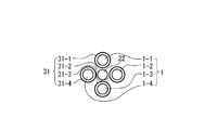
- 3B is a cross-sectional view taken along the line AA in FIG. 3A.
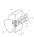
- FIG. 4 is a perspective view of the MPD thruster 200 according to the second embodiment, in which a part of the thruster is cut away.
- 5A to 5F are diagrams illustrating first to sixth examples of antennas (plasma generating antennas).
- FIG. 6 is a functional block diagram illustrating an example of an antenna operating device.
- the electrodeless plasma generator 3 includes a magnetic coil 21 and an antenna 31.
- the magnetic coil is a component of the acceleration device 2 and a component of the electrodeless plasma generator 3.
- the antenna 31 preferably includes a plurality of antennas 31-1, 31-2, 31-3, 31-4.
- the plurality of antennas 31-1, 31-2, 31-3, 31-4 are respectively arranged around the plurality of supply pipes 1-1, 1-2, 1-3, 1-4.
- the magnetic coil 21 is arranged so as to surround the supply pipes 1-1, 1-2, 1-3, 1-4 and the antennas 31-1, 31-2, 31-3, 31-4. In other words, the supply pipes 1-1, 1-2, 1-3, 1-4 around which the antenna is arranged cross the central region of the magnetic coil 21.
- the supply path 1 (or supply pipe) around which the antenna 31 is arranged is supported by support mechanisms 32, 33, and 34.
- the support mechanism 32 is a downstream support mechanism
- the support mechanism 33 is a central support mechanism
- the support mechanism 34 is an upstream support mechanism.
- Each of the support mechanisms 32, 33, and 34 also has a function as a spacer that supports each supply path 1 (or each supply pipe) and the cathode 22 separately.
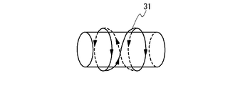
- the antenna 31 is a high frequency antenna.
- a helicon wave is generated by the interaction between the electric field induced by the high-frequency antenna and the axial magnetic field B t generated by the magnetic coil 21 (see FIG. 3A).
- the helicon wave acts on the propellant supplied to the supply path 1 to turn the propellant into plasma.
- helicon plasma which is electrodeless plasma is generated. Since helicon plasma can be generated at high density, it is preferable to use helicon plasma as electrodeless plasma.
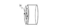
- FIG. 5A shows a first example of an antenna.
- the antenna of the first example is a loop antenna.
- FIG. 5B shows a second example of the antenna.
- the antenna of the second example is a Boswell antenna.
- FIG. 5C shows a third example of the antenna.
- the antenna of the third example is a saddle type antenna.
- FIG. 5D shows a fourth example of the antenna.
- the antenna of the fourth example is a Nagoya type 3 type antenna.
- a plurality of modes can be selected by changing the phase between the four coil currents.
- FIG. 5E shows a fifth example of the antenna.
- the antenna of the fifth example is a helical antenna.
- FIG. 5F shows a sixth example of the antenna.
- the antenna of the sixth example is a spiral antenna.
- the antenna can be applied to a large-diameter plasma supply path.
- the antenna operating device may include antennas 31-1, 31-2, 31-3, 31-4, an impedance matching unit 35, and a power supply device 36.
- the impedance matching unit 35 is for matching the input impedance on the power supply device 36 side with the load impedance on the antennas 31-1, 31-2, 31-3, 31-4 side.
- one power supply device 36 drives the plurality of antennas 31-1, 31-2, 31-3, 31-4 via the impedance matching unit 35.
- the number of power supply devices 36 is preferably one, but is not limited to one.
- the operation principle of the MPD thruster 200 in this embodiment is specified to use the magnetic coil 21 and the antenna 31 for generating electrodeless plasma, compared with the operation principle of the MPD thruster 100 in the first embodiment. It is different in point.
- (1) The propellant is supplied to the supply path 1.
- (3) The generated electrodeless plasma is supplied from the supply path 1 to the space S between the cathode 22 and the anode 23.
- the operation principle after the electrodeless plasma is supplied to the space S is the same as the operation principle of the first embodiment.
- electrodeless plasma is generated using the magnetic coil 21 of the acceleration device 2. That is, the acceleration magnetic field and the electrodeless plasma generation magnetic field are generated using the same magnetic coil 21. For this reason, the weight of the MPD thruster can be reduced. Moreover, the electric power required for the operation of the magnetic coil can be reduced. As a result, the propulsion efficiency of the MPD thruster is improved.
- the density of cations can be further increased. As a result, it is possible to increase the thrust of the MPD thruster.
- the weight of the thruster is reduced.
- the position of the outlet 7 of the supply path 1 is preferably upstream of the position of the anode 23.
- the position of the cathode 22 is preferably upstream of the position of the anode 23.
- a distance L2 between the supply path 1 (center of each supply path) and the central axis (X axis) of the magnetic coil 21 is a distance L1 between the cathode 22 (center of the cathode 22) and the central axis (X axis) of the magnetic coil 21. Larger is preferred.
- the distance L1 between the cathode 22 (the center of the cathode 22) and the central axis (X axis) of the magnetic coil 21 is zero, and the cathode 22 is preferably arranged along the central axis.
- the distance L2 between the supply path 1 (the center of each supply path) and the central axis (X axis) of the magnetic coil 21 is the anode 23 (the part of the anode 23 closest to the central axis of the coil) and the magnetic coil. It is preferable that the distance L3 to the center axis (X axis) 21 is smaller than L3.
- the radial magnetic field component B y perpendicular to the axial magnetic field component along the direction of the central axis of the magnetic coil 21 B x and the central axis is preferably generated.
- the MPD thruster apparatus configuration can be made compact.
- the axial magnetic field Bt is suitably generated inside the supply path 1 corresponding to the position of the antenna 31, and the generation efficiency of the electrodeless plasma is improved.
- FIG. 8 is a cross-sectional view showing a modification of the supply path 1 and is a cross-sectional view perpendicular to the X axis.
- the electrodeless plasma supply path 1 it is possible to arrange a supply path having a ring-shaped cross section instead of arranging a plurality of supply paths around the cathode 22.
Landscapes
- Engineering & Computer Science (AREA)
- Physics & Mathematics (AREA)
- Plasma & Fusion (AREA)
- Chemical & Material Sciences (AREA)
- Combustion & Propulsion (AREA)
- Spectroscopy & Molecular Physics (AREA)
- Electromagnetism (AREA)
- Mechanical Engineering (AREA)
- General Engineering & Computer Science (AREA)
- Plasma Technology (AREA)
Abstract
カソード(22)とアノード(23)の間の空間(S)に無電極プラズマを供給して、前記空間内の電気抵抗率を下げ、前記空間(S)に生成される軸方向磁場成分(Bx)及び径方向磁場成分(By)と、前記空間(S)を流れる電流(Iac)とによって誘起されるローレンツ力によって、前記無電極プラズマを加速する。
Description
本発明は、無電極プラズマを加速するMPDスラスタ、及び、MPDスラスタを用いて無電極プラズマを加速する方法に関する。
宇宙で使用される推進装置として、MPDスラスタ(Magneto-Plasma-Dynamic thruster)が知られている。図1に、MPDスラスタの例を示す。例示のMPDスラスタは、アーク放電によって推進剤(ガス)を電離することでプラズマを生成する。そして、スラスタの外周側に配置されたアノードと、中心側に配置されたカソードとの間に流れる電流と、その電流によって生成される磁場(又は、予め印加された磁場)によってローレンツ力が発生する。前記ローレンツ力によって、生成されたプラズマは加速される。
宇宙で使用される推進装置に関連する技術として、特許文献1には、アーク放電により形成されたプラズマを、ノズルから排出することで推力を得る電気推進機が開示されている。特許文献2には、放電により形成された荷電粒子を、スクリーン電極及び加速電極を用いて、選択的に加速するイオンエンジンが開示されている。
本発明におけるMPDスラスタは、推進剤から無電極プラズマを生成する無電極プラズマ生成装置と、前記無電極プラズマを加速させる加速装置と、生成された前記無電極プラズマを、前記加速装置に供給する供給路と、を備える。また、前記加速装置は、磁気コイルと、カソードと、アノードと、前記カソードと前記アノードの間に電圧を印加する電圧印加装置と、を備える。さらに、前記供給路は、前記カソードと前記アノードの間の空間に前記無電極プラズマを供給する。また、前記磁気コイルは、前記空間内に、前記磁気コイルの中心軸の方向に沿う軸方向磁場成分及び前記中心軸に直交する径方向磁場成分を生成する。加えて、前記電圧印加装置は、前記空間内に電流を生成する。また、前記空間に供給される前記無電極プラズマは、前記軸方向磁場成分及び前記径方向磁場成分と、前記電流とによって誘起されるローレンツ力によって、前記無電極プラズマを加速する。
本発明における無電極プラズマを加速する方法は、MPDスラスタを用いて無電極プラズマを加速する方法である。無電極プラズマを加速する方法は、カソードとアノードの間の空間に無電極プラズマを供給して、前記空間内の電気抵抗率を下げる工程と、前記空間内に、前記MPDスラスタの中心軸の方向に沿う軸方向磁場成分及び前記中心軸に直交する径方向磁場成分を生成する工程と、前記空間内に電流を生成する工程と、前記軸方向磁場成分及び前記径方向磁場成分と、前記電流とによって誘起されるローレンツ力によって、前記無電極プラズマを加速する工程とを備える。
上記構成によって、供給電力を抑制し、電極損耗を低減し、推進効率を向上させることが可能なMPDスラスタが提供される。
この発明の目的と利益とは以下の説明と添付図面とによって容易に確認することができる。
添付の図面は、実施形態の説明を助けるために本明細書に組み込まれる。図面は、本発明を、図示された例および説明された例に限定するものとして解釈されるべきではない。
図1は、従来のMPDスラスタの構成を模式的に示す断面図である。
図2Aは、本発明の第1の実施形態のMPDスラスタの構成を模式的に示す断面図である。
図2Bは、図2AのA-A矢視断面図である。
図2Cは、図2AのC-C矢視断面図である。
図3Aは、本発明の第2の実施形態のMPDスラスタの構成を模式的に示す断面図である。
図3Bは、図3AのA-A矢視断面図である。
図4は、第2の実施形態のMPDスラスタの斜視図であって、スラスタの一部分を切り欠いた斜視図である。
図5Aは、アンテナ(プラズマ生成アンテナ)の第1例を示す図である。
図5Bは、アンテナ(プラズマ生成アンテナ)の第2例を示す図である。
図5Cは、アンテナ(プラズマ生成アンテナ)の第3例を示す図である。
図5Dは、アンテナ(プラズマ生成アンテナ)の第4例を示す図である。
図5Eは、アンテナ(プラズマ生成アンテナ)の第5例を示す図である。
図5Fは、アンテナ(プラズマ生成アンテナ)の第6例を示す図である。
図6は、本発明の第2の実施形態において、アンテナの作動装置の一例を示す機能ブロック図である。
図7は、本発明の実施形態において、供給路、カソード、アノードの位置関係、及び、供給路、アンテナ、磁気コイルの位置関係について示す模式図である。
図8は、本発明の実施形態において、供給路の変形例を示す断面図であって、X軸に垂直な断面図である。
以下、本発明の実施形態に係るMPDスラスタに関して、添付図面を参照して説明する。
以下の詳細な説明においては、実施形態の包括的な理解を提供するために、説明の目的で多くの詳細な特定事項が開示される。しかし、一又は複数の実施形態は、これらの詳細な特定事項なしで実行可能であることが明らかである。また、周知の構造又は周知の装置は、図面を簡潔なものとするために概要のみが示されている。
以下の詳細な説明においては、実施形態の包括的な理解を提供するために、説明の目的で多くの詳細な特定事項が開示される。しかし、一又は複数の実施形態は、これらの詳細な特定事項なしで実行可能であることが明らかである。また、周知の構造又は周知の装置は、図面を簡潔なものとするために概要のみが示されている。
(座標系の定義)
図2A、図3Aを参照して、座標系の定義を行う。X方向は、MPDスラスタ100、200の前後方向であり、+X方向は、MPDスラスタ100、200の後ろ方向、すなわち、ノズル側の方向を意味する。φ方向は、MPDスラスタ100、200の中心軸であるX軸まわりの回転方向であり、+φ方向は、+X方向にみて時計回りを意味する。
図2A、図3Aを参照して、座標系の定義を行う。X方向は、MPDスラスタ100、200の前後方向であり、+X方向は、MPDスラスタ100、200の後ろ方向、すなわち、ノズル側の方向を意味する。φ方向は、MPDスラスタ100、200の中心軸であるX軸まわりの回転方向であり、+φ方向は、+X方向にみて時計回りを意味する。
(重要な用語の定義)
本実施の形態において、+X方向の側を「下流側」と定義し、-X方向の側を「上流側」と定義する。また、「無電極プラズマ」は、無電極プラズマ生成装置で生成されたプラズマと定義する。「無電極プラズマ生成装置」は、プラズマの生成過程において、電極とプラズマとが直接接触することのないプラズマ生成装置と定義する。
本実施の形態において、+X方向の側を「下流側」と定義し、-X方向の側を「上流側」と定義する。また、「無電極プラズマ」は、無電極プラズマ生成装置で生成されたプラズマと定義する。「無電極プラズマ生成装置」は、プラズマの生成過程において、電極とプラズマとが直接接触することのないプラズマ生成装置と定義する。
(第1の実施形態)
図2A乃至図2Cを参照して、第1の実施形態に係るMPDスラスタについて説明する。図2Aは、第1の実施形態のMPDスラスタ100の構成を模式的に示す断面図である。また、図2B、図2Cは、それぞれ、図2AのA-A矢視断面図、図2AのC-C矢視断面図である。
図2A乃至図2Cを参照して、第1の実施形態に係るMPDスラスタについて説明する。図2Aは、第1の実施形態のMPDスラスタ100の構成を模式的に示す断面図である。また、図2B、図2Cは、それぞれ、図2AのA-A矢視断面図、図2AのC-C矢視断面図である。
1.MPDスラスタ100の構成
MPDスラスタ100は、無電極プラズマを供給する供給路1と、加速装置2と、無電極プラズマ生成装置(図示せず)を備える。
MPDスラスタ100は、無電極プラズマを供給する供給路1と、加速装置2と、無電極プラズマ生成装置(図示せず)を備える。
(供給路1)
供給路1は、例えば、4つの供給管1-1、1-2、1-3、1-4で構成される。なお、供給管の数は4つに限定されず、任意である。また前記供給管の内径は20mm以上、100mm以下であってもよい。また、供給管を複数配置する場合には、前記供給管を、後述のカソード22の周囲に等間隔で配置することが好ましい。なお、カソード22と前記供給管との間は接することがない程度に離間してもよい。供給路1内には推進剤が供給される。推進剤は、例えば、アルゴンガス、キセノンガス等のガスである。そして、供給路1に供給された推進剤は、無電極プラズマ生成装置によって、陽イオンP+と電子e-とに電離され(プラズマ化され)、無電極プラズマが生成される。なお、無電極プラズマ生成装置は、無電極プラズマを生成する装置であればどのような装置であってもよい。代替的に、無電極プラズマ生成装置で予め生成された無電極プラズマが、供給路1に供給されるようにしてもよい。供給路1内の無電極プラズマは、加速装置2に供給される。より詳細には、無電極プラズマは、カソード22とアノード23の間の空間Sに供給される。
供給路1は、例えば、4つの供給管1-1、1-2、1-3、1-4で構成される。なお、供給管の数は4つに限定されず、任意である。また前記供給管の内径は20mm以上、100mm以下であってもよい。また、供給管を複数配置する場合には、前記供給管を、後述のカソード22の周囲に等間隔で配置することが好ましい。なお、カソード22と前記供給管との間は接することがない程度に離間してもよい。供給路1内には推進剤が供給される。推進剤は、例えば、アルゴンガス、キセノンガス等のガスである。そして、供給路1に供給された推進剤は、無電極プラズマ生成装置によって、陽イオンP+と電子e-とに電離され(プラズマ化され)、無電極プラズマが生成される。なお、無電極プラズマ生成装置は、無電極プラズマを生成する装置であればどのような装置であってもよい。代替的に、無電極プラズマ生成装置で予め生成された無電極プラズマが、供給路1に供給されるようにしてもよい。供給路1内の無電極プラズマは、加速装置2に供給される。より詳細には、無電極プラズマは、カソード22とアノード23の間の空間Sに供給される。
(加速装置2)
加速装置2は、磁気コイル21、カソード22、アノード23、電圧印加装置24を備える。磁気コイル21は、供給路1を囲むように配置される。換言すれば、供給路1は、磁気コイル21の中央領域を横断する。ここで、磁気コイル21の中央領域とは、磁気コイル21の内径の内側の空洞領域を意味する。磁気コイル21の中心軸は、X軸に一致していることが好ましい。磁気コイル21は、カソード22とアノード23の間の空間Sに、磁場Bを発生させる。磁場Bは、磁気コイル21の中心軸(X軸)に沿う成分である軸方向磁場成分Bxと、中心軸(X軸)に直交する成分である径方向磁場成分Byを含む。カソード22は、電子を放出する。カソード22は、好ましくは、微細孔を備えたホローカソードである。アノード23は、カソードの下流側に配置される。アノード23は、ノズル25の内面の少なくとも一部を構成するプレートで構成することが好ましい。なお、アノード23は、複数の部分に分割された分割体の組み合わせによって構成されてもよい。また、ノズル25は、下流側に向かって拡開する傾斜内面を有するノズルであることが好ましい。電圧印加装置24は、カソード22とアノード23の間に電圧を印加し、カソード22とアノード23の間に、すなわち、空間Sに、電流Iacを発生させる。なお、図2Aにおいて、電圧印加装置24とカソード22とを接続する配線、及び、電圧印加装置24とアノード23とを接続する配線は、説明をわかりやすくするために便宜的に記載したものである。よって、実際の配線の配置は、図2Aの配置に限定されず、適宜設計される事項である。前記電流Iacは、ホローカソードを用いない場合には、放電電流である。前記電流Iacは、ホローカソードを用いる場合には、ホローカソードから放出される熱電子の流れに基づく電流である。加速装置2は、前記磁場B及び前記電流Iacにより誘起されるローレンツ力によって、供給路1から供給される無電極プラズマを、下流側に向けて加速する。
加速装置2は、磁気コイル21、カソード22、アノード23、電圧印加装置24を備える。磁気コイル21は、供給路1を囲むように配置される。換言すれば、供給路1は、磁気コイル21の中央領域を横断する。ここで、磁気コイル21の中央領域とは、磁気コイル21の内径の内側の空洞領域を意味する。磁気コイル21の中心軸は、X軸に一致していることが好ましい。磁気コイル21は、カソード22とアノード23の間の空間Sに、磁場Bを発生させる。磁場Bは、磁気コイル21の中心軸(X軸)に沿う成分である軸方向磁場成分Bxと、中心軸(X軸)に直交する成分である径方向磁場成分Byを含む。カソード22は、電子を放出する。カソード22は、好ましくは、微細孔を備えたホローカソードである。アノード23は、カソードの下流側に配置される。アノード23は、ノズル25の内面の少なくとも一部を構成するプレートで構成することが好ましい。なお、アノード23は、複数の部分に分割された分割体の組み合わせによって構成されてもよい。また、ノズル25は、下流側に向かって拡開する傾斜内面を有するノズルであることが好ましい。電圧印加装置24は、カソード22とアノード23の間に電圧を印加し、カソード22とアノード23の間に、すなわち、空間Sに、電流Iacを発生させる。なお、図2Aにおいて、電圧印加装置24とカソード22とを接続する配線、及び、電圧印加装置24とアノード23とを接続する配線は、説明をわかりやすくするために便宜的に記載したものである。よって、実際の配線の配置は、図2Aの配置に限定されず、適宜設計される事項である。前記電流Iacは、ホローカソードを用いない場合には、放電電流である。前記電流Iacは、ホローカソードを用いる場合には、ホローカソードから放出される熱電子の流れに基づく電流である。加速装置2は、前記磁場B及び前記電流Iacにより誘起されるローレンツ力によって、供給路1から供給される無電極プラズマを、下流側に向けて加速する。
加速装置2のカソードが、ホローカソードである場合について、より詳細に説明する。ホローカソードは、化学物質からなるインサートを備える。このインサートを例えば加熱装置により加熱すると、インサートは熱電子を放出する。放出された熱電子は、ホローカソード内に供給される作動ガスと衝突し、ホローカソード内でプラズマを発生させる。カソードの出口に、正電極を配置すると、プラズマの中から電子がカソード外に放出される。カソードの作動前には加熱装置を用いてインサートを加熱するが、一旦カソードが作動すると、プラズマが発生する熱によって電子を放出することが可能である。
2.MPDスラスタ100の作動原理
次に、MPDスラスタ100の作動原理について説明する。
(1)供給路1から、カソード22とアノード23の間の空間Sに、無電極プラズマ(陽イオンP+及び電子e-)が供給される。当該供給により、カソード22とアノード23の間の空間Sの電気抵抗率は低下する。
(2)磁気コイル21を作動させることにより、空間Sに、軸方向磁場成分Bxと径方向磁場成分Byとを含む磁場Bが生成される。
(3)カソード22とアノード23との間に電圧及び電力が印加され、空間Sに電流Iacが流れる。当該電流Iacは、カソード22とアノード23との間の放電電流であってもよいし、ホローカソードから放出される熱電子の流れに基づく電流であってもよい。空間Sの電気抵抗率は低下しているため、印加する前記電圧及び電力を、従来のMPDスラスタと比較して、小さくすることが可能である。なお、上記(1)、(2)、(3)の工程を開始する順番は任意である。また、上記(1)、(2)、(3)の工程を同時に開始してもよい。
(4)空間Sに存在する電子e-(カソード22から放出される電子、及び、無電極プラズマに含まれる電子)の一部は、アノード23によって捕捉される(電流Iacを担う)。また、空間Sに存在する電子e-の一部は、ローレンツ力により、下流に向かって加速され、ノズル25から下流側に向けて放出される。なお、前記ローレンツ力による加速のメカニズムの概要は下記(4a)(4b)のとおりである。
(4a)前記電流Iacの径方向成分(X軸に向かう成分)と、前記軸方向磁場成分Bxとによって誘起されるローレンツ力により、電子e-は、磁気コイル21の中心軸(X軸)まわりに+φ方向に回転する。
(4b)前記回転により、-φ方向の電流が流れる。-φ方向の電流と、前記径方向磁場成分Byとによって誘起されるローレンツ力により、電子e-は、+X方向に加速される。なお、上記(4a)(4b)は、実際には、同時並行的に進行する現象である。
(5)+X方向、すなわち、下流側に向かって加速される電子e-は、クーロン力によって、陽イオンP+を牽引し、陽イオンP+を下流側に向かって加速させる。そして、前記陽イオンP+は、ノズル25から下流側に向けて放出される。前記放出に伴う反力により、MPDスラスタ100は推力を得る。
(6)なお、前記アノード23と、ノズル25から放出された電子e-との間には、電場勾配が存在する。よって、陽イオンP+は、前記電場勾配によっても、下流側に向かって加速される。
供給路1から供給される無電極プラズマは、プラズマの生成過程において、電極とプラズマとが直接接触することなく生成されたプラズマである。このような無電極プラズマは、電極とプラズマとが接触しない加速装置を用いて加速されることが一般的である。これに対し、本実施形態は、無電極プラズマを、プラズマと接触する電極(アノード及びカソード)を備えた加速装置2によって加速するものである。
3.効果
本実施形態では、空間Sに無電極プラズマが供給され、空間Sの電気抵抗率が低下される。このため、カソードとアノードとの間に印加する電圧及び電力を、従来のMPDスラスタと比較して小さくすることが可能である。その結果、MPDスラスタの作動効率が向上する。また、前記電力を小さくすることにより、MPDスラスタの温度上昇を抑制することができる。その結果、MPDスラスタを長時間作動させることができる。
本実施形態では、空間Sに無電極プラズマが供給され、空間Sの電気抵抗率が低下される。このため、カソードとアノードとの間に印加する電圧及び電力を、従来のMPDスラスタと比較して小さくすることが可能である。その結果、MPDスラスタの作動効率が向上する。また、前記電力を小さくすることにより、MPDスラスタの温度上昇を抑制することができる。その結果、MPDスラスタを長時間作動させることができる。
本実施形態のカソードとして、ホローカソードを用いた場合には、付加的に、次の効果を奏する。第1に、放電によるカソードの損耗が抑制されるため、電極を長寿命化することができる。第2に、ホローカソードによって放出される熱電子の量を制御することで、上述のローレンツ力の強さを制御することが可能となる。
本実施形態では、無電極プラズマを用いる。無電極プラズマの陽イオン密度は、アーク放電によって生成されるプラズマの陽イオン密度と同程度以上のものが得られるだけでなく、後者では陽光柱と呼ばれるごく限られた領域にのみ高密度領域が得られるのに対して、前者ではほぼ全放電領域に渡って高密度領域を形成することができる。このため、生成できる陽イオンの割合はアーク放電の100倍程度にすることも可能で、その結果、MPDスラスタの大推力化が可能である。
本実施形態では、無電極プラズマは、供給路1から供給される。このため、加速装置内で、アーク放電又は熱電子を用いて推進剤をプラズマ化する工程が不要である。その結果、MPDスラスタの推進効率が向上する。
また、実施形態におけるMPDスラスタによれば、次のような課題を克服することが可能である。
(電力又は熱に関する課題)
MPDスラスタは、プラズマ生成のためにアーク放電を用いる場合がある。アーク放電を発生させるためには、大きな電力が必要となる。また、大きな電力を投入するため、スラスタ自体の温度が高温になりやすい。このため、MPDスラスタは、定常的な作動を実現することが難しい場合がある。よってMPDスラスタは、推進効率が低く、電力供給量及び排熱量に制約のある宇宙機への適用が難しい場合がある。
MPDスラスタは、プラズマ生成のためにアーク放電を用いる場合がある。アーク放電を発生させるためには、大きな電力が必要となる。また、大きな電力を投入するため、スラスタ自体の温度が高温になりやすい。このため、MPDスラスタは、定常的な作動を実現することが難しい場合がある。よってMPDスラスタは、推進効率が低く、電力供給量及び排熱量に制約のある宇宙機への適用が難しい場合がある。
(電極損耗に関する課題)
MPDスラスタでは、アーク放電によって、スラスタのカソードが損耗する場合がある。このため、作動寿命を長くすることが難しい。作動寿命を長くするために、カソードとして、ホローカソードを用いることが考えられる。しかし、ホローカソードを用いる際には、推進効率に関する課題が存在する場合がある。
MPDスラスタでは、アーク放電によって、スラスタのカソードが損耗する場合がある。このため、作動寿命を長くすることが難しい。作動寿命を長くするために、カソードとして、ホローカソードを用いることが考えられる。しかし、ホローカソードを用いる際には、推進効率に関する課題が存在する場合がある。
(推進効率に関する課題)
効率的に推進力を得るためには、電子に比べて質量の大きい陽イオンの密度を上げることが考えられる。しかし、上記ホローカソードからは、陽イオンは僅かしか出力されない場合がある。このため、ホローカソードから放出される熱電子を推進剤ガスに衝突させることにより、陽イオンの密度を上げることが考えられる。しかし、熱電子を生成して、推進剤ガスに衝突させることは、効率的ではない。よって、ホローカソードを用いた場合であっても、推進効率を向上させることが難しい場合がある。
効率的に推進力を得るためには、電子に比べて質量の大きい陽イオンの密度を上げることが考えられる。しかし、上記ホローカソードからは、陽イオンは僅かしか出力されない場合がある。このため、ホローカソードから放出される熱電子を推進剤ガスに衝突させることにより、陽イオンの密度を上げることが考えられる。しかし、熱電子を生成して、推進剤ガスに衝突させることは、効率的ではない。よって、ホローカソードを用いた場合であっても、推進効率を向上させることが難しい場合がある。
(第2の実施形態)
図3A乃至図6を参照して、第2の実施形態に係るプラズマ加速装置について説明する。
図3A乃至図6を参照して、第2の実施形態に係るプラズマ加速装置について説明する。
第2の実施形態において、第1の実施形態と同じ構成要素については、同じ図番を用いている。
1.MPDスラスタ200の構成
MPDスラスタ200は、無電極プラズマを供給する供給路1と、加速装置2と、無電極プラズマ生成装置3を備える。
MPDスラスタ200は、無電極プラズマを供給する供給路1と、加速装置2と、無電極プラズマ生成装置3を備える。
(無電極プラズマ生成装置3)
図3A乃至図6を参照して、無電極プラズマ生成装置3について説明する。図3Aは、第2の実施形態のMPDスラスタ200の構成を模式的に示す断面図である。図3Bは、図3AのA-A矢視断面図である。図4は、第2の実施形態のMPDスラスタ200の斜視図であって、スラスタの一部分を切り欠いた斜視図である。また、図5A乃至図5Fは、アンテナ(プラズマ生成アンテナ)の第1例乃至第6例を示す図である。図6は、アンテナの作動装置の一例を示す機能ブロック図である。
図3A乃至図6を参照して、無電極プラズマ生成装置3について説明する。図3Aは、第2の実施形態のMPDスラスタ200の構成を模式的に示す断面図である。図3Bは、図3AのA-A矢視断面図である。図4は、第2の実施形態のMPDスラスタ200の斜視図であって、スラスタの一部分を切り欠いた斜視図である。また、図5A乃至図5Fは、アンテナ(プラズマ生成アンテナ)の第1例乃至第6例を示す図である。図6は、アンテナの作動装置の一例を示す機能ブロック図である。
無電極プラズマ生成装置3は、磁気コイル21及びアンテナ31を含む。磁気コイルは、加速装置2の構成要素であるとともに、無電極プラズマ生成装置3の構成要素でもある。アンテナ31は、複数のアンテナ31-1、31-2、31-3、31-4を含むことが好ましい。複数のアンテナ31-1、31-2、31-3、31-4は、複数の供給管1-1、1-2、1-3、1-4の周囲に、それぞれ配置される。また、磁気コイル21は、供給管1-1、1-2、1-3、1-4及びアンテナ31-1、31-2、31-3、31-4を囲むように配置される。換言すれば、アンテナが周囲に配置された供給管1-1、1-2、1-3、1-4は、磁気コイル21の中央領域を横断する。なお、図3Bには、4つの供給管、及び、4つのアンテナが記載されている。しかし、供給管の数、及び、アンテナの数は、4つに限定されず、任意である。図4に示されるように、アンテナ31が周囲に配置された供給路1(又は供給管)は、支持機構32、33、34によって支持される。支持機構32は、下流側支持機構であり、支持機構33は、中央支持機構であり、支持機構34は、上流側支持機構である。各支持機構32、33、34は、各供給路1(又は各供給管)とカソード22とを離間させて支持するスペーサとしての機能も有している。
アンテナ31は、高周波アンテナである。高周波アンテナにより誘起される電場、及び、磁気コイル21により生成される軸方向磁場Bt(図3Aを参照。)の相互作用により、ヘリコン波が発生する。ヘリコン波は、供給路1に供給される推進剤に作用して、推進剤をプラズマ化する。その結果、無電極プラズマであるヘリコンプラズマが生成される。ヘリコンプラズマは、高密度で生成することが可能であるため、無電極プラズマとしてヘリコンプラズマを採用することが好ましい。
アンテナ31としては、種々の形態のアンテナを採用し得る。図5Aは、アンテナの第1例を示す。第1例のアンテナは、ループアンテナである。図5Bは、アンテナの第2例を示す。第2例のアンテナは、Boswellアンテナである。図5Cは、アンテナの第3例を示す。第3例のアンテナは、サドル型アンテナである。図5Dは、アンテナの第4例を示す。第4例のアンテナは、名古屋タイプ3型アンテナである。当該アンテナでは、4個のコイル電流間の位相を変えることにより複数のモードの選択が可能である。図5Eは、アンテナの第5例を示す。第5例のアンテナは、ヘリカルアンテナである。図5Fは、アンテナの第6例を示す。第6例のアンテナは、スパイラル型アンテナである。当該アンテナは、大口径のプラズマ供給路に適用可能である。
図6に示されるように、アンテナの作動装置は、アンテナ31-1、31-2、31-3、31-4、インピーダンス整合器35、電源装置36を備えていてもよい。インピーダンス整合器35は、電源装置36側の入力インピーダンスと、アンテナ31-1、31-2、31-3、31-4側の負荷インピーダンスとを整合させるためのものである。本実施形態では、1つの電源装置36が、インピーダンス整合器35を介して、複数のアンテナ31-1、31-2、31-3、31-4を駆動する。なお、電源装置36は、1つであることが好ましいが、1つであることには限定されない。
2.MPDスラスタ200の作動原理
次に、MPDスラスタ200の作動原理について説明する。本実施形態におけるMPDスラスタ200の作動原理は、第1の実施形態におけるMPDスラスタ100の作動原理と比較して、無電極プラズマの生成に、磁気コイル21及びアンテナ31を用いることが特定されている点で異なる。
(1)供給路1に推進剤が供給される。
(2)アンテナ31によって誘起される電場、及び、磁気コイル21により生成される軸方向磁場Btの相互作用により、無電極プラズマが生成される。
(3)生成された無電極プラズマは、供給路1から、カソード22とアノード23の間の空間Sに供給される。空間Sに無電極プラズマが供給された後の作動原理については、第1の実施形態の作動原理と同様である。
3.効果
本実施形態では、加速装置2の磁気コイル21を用いて、無電極プラズマを生成する。すなわち、加速用の磁場と、無電極プラズマ生成用の磁場とを、同一の磁気コイル21を用いて生成している。このため、MPDスラスタの重量を低減することができる。また、磁気コイルの作動に必要となる電力を低減することができる。その結果、MPDスラスタの推進効率が向上する。
本実施形態では、加速装置2の磁気コイル21を用いて、無電極プラズマを生成する。すなわち、加速用の磁場と、無電極プラズマ生成用の磁場とを、同一の磁気コイル21を用いて生成している。このため、MPDスラスタの重量を低減することができる。また、磁気コイルの作動に必要となる電力を低減することができる。その結果、MPDスラスタの推進効率が向上する。
本実施形態において、ヘリコンプラズマを生成する場合には、陽イオンの密度を更に高くすることが可能である。その結果、MPDスラスタの大推力化が可能である。
本実施形態において、一つの電源装置で複数のアンテナを駆動する場合には、スラスタの重量が低減される。
(供給路1、カソード22、アノード23の位置関係)
図7を参照して、本発明の実施形態における、供給路1、カソード22、アノード23の位置関係の具体例について説明する。供給路1の出口7の位置は、アノード23の位置よりも上流側であることが好ましい。また、カソード22の位置は、アノード23の位置よりも上流側であることが好ましい。供給路1(各供給路の中心)と磁気コイル21の中心軸(X軸)との距離L2は、カソード22(カソード22の中心)と磁気コイル21の中心軸(X軸)との距離L1より大きいことが好ましい。なお、カソード22(カソード22の中心)と磁気コイル21の中心軸(X軸)との距離L1はゼロであり、カソード22は、前記中心軸に沿って配置されることが好ましい。また、供給路1(各供給路の中心)と磁気コイル21の中心軸(X軸)との距離L2は、アノード23(アノード23のうち、コイルの中心軸に一番近い部分)と磁気コイル21の中心軸(X軸)との距離L3より小さいことが好ましい。
図7を参照して、本発明の実施形態における、供給路1、カソード22、アノード23の位置関係の具体例について説明する。供給路1の出口7の位置は、アノード23の位置よりも上流側であることが好ましい。また、カソード22の位置は、アノード23の位置よりも上流側であることが好ましい。供給路1(各供給路の中心)と磁気コイル21の中心軸(X軸)との距離L2は、カソード22(カソード22の中心)と磁気コイル21の中心軸(X軸)との距離L1より大きいことが好ましい。なお、カソード22(カソード22の中心)と磁気コイル21の中心軸(X軸)との距離L1はゼロであり、カソード22は、前記中心軸に沿って配置されることが好ましい。また、供給路1(各供給路の中心)と磁気コイル21の中心軸(X軸)との距離L2は、アノード23(アノード23のうち、コイルの中心軸に一番近い部分)と磁気コイル21の中心軸(X軸)との距離L3より小さいことが好ましい。
上述の位置関係を採用することにより、磁気コイル21の中心軸の方向に沿う軸方向磁場成分Bx及び前記中心軸に直交する径方向磁場成分Byが好適に生成される。また、MPDスラスタの装置構成をコンパクトにすることができる。
(供給路1、アンテナ31、磁気コイル21の位置関係)
次に、図7を参照して、供給路1の周囲にアンテナ31を配置する場合において、供給路1、アンテナ31、磁気コイル21の位置関係の具体例について説明する。アンテナ31と磁気コイル21とは、少なくとも一部が磁気コイル21の中心軸方向(X軸方向)にオーバーラップして配置されることが好ましい。例えば、磁気コイル21の中心軸方向全長にわたって、アンテナ31と磁気コイル21とがオーバーラップするように配置される。
次に、図7を参照して、供給路1の周囲にアンテナ31を配置する場合において、供給路1、アンテナ31、磁気コイル21の位置関係の具体例について説明する。アンテナ31と磁気コイル21とは、少なくとも一部が磁気コイル21の中心軸方向(X軸方向)にオーバーラップして配置されることが好ましい。例えば、磁気コイル21の中心軸方向全長にわたって、アンテナ31と磁気コイル21とがオーバーラップするように配置される。
上述の位置関係を採用することにより、アンテナ31の位置に対応する供給路1の内部に、軸方向磁場Btが好適に生成され、無電極プラズマの生成効率が向上する。
(供給路1の変形例)
図8は、供給路1の変形例を示す断面図であって、X軸に垂直な断面図である。図8に示されるように、無電極プラズマの供給路1として、カソード22の周囲に複数の供給路を配置する代わりに、断面リング状の供給路を配置することが可能である。
図8は、供給路1の変形例を示す断面図であって、X軸に垂直な断面図である。図8に示されるように、無電極プラズマの供給路1として、カソード22の周囲に複数の供給路を配置する代わりに、断面リング状の供給路を配置することが可能である。
本発明は上記各実施の形態に限定されず、本発明の技術思想の範囲内において、各実施の形態は適宜変形又は変更され得ることは明らかである。また、各実施の形態で用いられる種々の技術は、技術的矛盾が生じない限り、他の実施の形態にも適用可能である。
本出願は、2014年5月23日に出願された日本国特許出願第2014-107583号を基礎とする優先権を主張し、当該基礎出願の開示の全てを引用により本出願に取り込む。
Claims (10)
- MPDスラスタであって、
推進剤から無電極プラズマを生成する無電極プラズマ生成装置と、
前記無電極プラズマを加速させる加速装置と、
生成された前記無電極プラズマを、前記加速装置に供給する供給路と、
を備え、
前記加速装置は、
磁気コイルと、
カソードと、
アノードと、
前記カソードと前記アノードの間に電圧を印加する電圧印加装置と、
を備え、
前記供給路は、前記カソードと前記アノードの間の空間に前記無電極プラズマを供給し、
前記磁気コイルは、前記空間内に、前記磁気コイルの中心軸の方向に沿う軸方向磁場成分及び前記中心軸に直交する径方向磁場成分を生成し、
前記電圧印加装置は、前記空間内に電流を生成し、
前記空間に供給される前記無電極プラズマは、前記軸方向磁場成分及び前記径方向磁場成分と、前記電流とによって誘起されるローレンツ力によって、前記無電極プラズマを加速する
MPDスラスタ。 - 請求項1に記載のMPDスラスタにおいて、
前記供給路と前記磁気コイルの前記中心軸との距離は、前記カソードと前記中心軸との距離より大きく、前記アノードと前記中心軸との距離より小さい
MPDスラスタ。 - 請求項1又は2に記載のMPDスラスタにおいて、
前記カソードは、前記磁気コイルの前記中心軸に沿って配置される
MPDスラスタ。 - 請求項1乃至3のいずれか一項に記載のMPDスラスタにおいて、
前記無電極プラズマ生成装置は、
前記供給路の周囲に配置されるアンテナ
を備え、
前記無電極プラズマ生成装置は、前記アンテナにより誘起される電場と、前記磁気コイルにより生成される磁場との相互作用により、前記推進剤をプラズマ化する
MPDスラスタ。 - 請求項4に記載のMPDスラスタにおいて、
前記供給路は、複数の供給管を含み、
前記複数の供給管は、前記カソードの周囲に等間隔で配置され、
前記無電極プラズマ生成装置は、前記アンテナを複数備え、
前記複数の供給管の各々の周囲には、複数の前記アンテナのうちの1つが配置される
MPDスラスタ。 - 請求項5に記載のMPDスラスタにおいて、
前記無電極プラズマ生成装置は、
1つの電源装置と、
インピーダンス整合器と、
を更に備え、
前記1つの電源装置は、前記インピーダンス整合器を介して、複数の前記アンテナを駆動する
MPDスラスタ。 - 請求項4乃至6のいずれか一項に記載のMPDスラスタにおいて、
前記アンテナは、ヘリカルアンテナであり、
前記無電極プラズマは、ヘリコンプラズマである
MPDスラスタ。 - 請求項1乃至7のいずれか一項に記載のMPDスラスタにおいて、
前記カソードは、ホローカソードである
MPDスラスタ。 - 請求項1乃至8のいずれか一項に記載のMPDスラスタにおいて、
前記無電極プラズマを放出するノズル
を更に備え、
前記アノードは、前記ノズルの内面の少なくとも一部を構成する
MPDスラスタ。 - MPDスラスタを用いて無電極プラズマを加速する方法であって、
カソードとアノードの間の空間に無電極プラズマを供給して、前記空間内の電気抵抗率を下げる工程と、
前記空間内に、前記MPDスラスタの中心軸の方向に沿う軸方向磁場成分及び前記中心軸に直交する径方向磁場成分を生成する工程と、
前記空間内に電流を生成する工程と、
前記軸方向磁場成分及び前記径方向磁場成分と、前記電流とによって誘起されるローレンツ力によって、前記無電極プラズマを加速する工程と
を備える方法。
Priority Applications (2)
| Application Number | Priority Date | Filing Date | Title |
|---|---|---|---|
| US15/313,746 US10260487B2 (en) | 2014-05-23 | 2014-08-25 | MPD thruster that accelerates electrodeless plasma and electrodeless plasma accelerating method using MPD thruster |
| EP14892356.8A EP3139041B1 (en) | 2014-05-23 | 2014-08-25 | Magnetoplasmadynamic (mpd) thruster that accelerates electrodeless plasma, and electrodeless plasma accelerating method using mpd thruster |
Applications Claiming Priority (2)
| Application Number | Priority Date | Filing Date | Title |
|---|---|---|---|
| JP2014-107583 | 2014-05-23 | ||
| JP2014107583A JP6467659B2 (ja) | 2014-05-23 | 2014-05-23 | 無電極プラズマを加速するmpdスラスタ、及び、mpdスラスタを用いて無電極プラズマを加速する方法 |
Publications (1)
| Publication Number | Publication Date |
|---|---|
| WO2015177942A1 true WO2015177942A1 (ja) | 2015-11-26 |
Family
ID=54553632
Family Applications (1)
| Application Number | Title | Priority Date | Filing Date |
|---|---|---|---|
| PCT/JP2014/072147 WO2015177942A1 (ja) | 2014-05-23 | 2014-08-25 | 無電極プラズマを加速するmpdスラスタ、及び、mpdスラスタを用いて無電極プラズマを加速する方法 |
Country Status (4)
| Country | Link |
|---|---|
| US (1) | US10260487B2 (ja) |
| EP (1) | EP3139041B1 (ja) |
| JP (1) | JP6467659B2 (ja) |
| WO (1) | WO2015177942A1 (ja) |
Cited By (2)
| Publication number | Priority date | Publication date | Assignee | Title |
|---|---|---|---|---|
| CN112943572A (zh) * | 2021-03-23 | 2021-06-11 | 哈尔滨工业大学 | 一种改变霍尔推力器磁场后加载程度的磁路结构 |
| GB2600493A (en) * | 2020-11-03 | 2022-05-04 | Neutronstar Systems Ug | Propulsion unit for spacecraft |
Families Citing this family (5)
| Publication number | Priority date | Publication date | Assignee | Title |
|---|---|---|---|---|
| JP6745134B2 (ja) * | 2016-05-12 | 2020-08-26 | 東京エレクトロン株式会社 | プラズマ処理装置 |
| WO2019075051A1 (en) | 2017-10-10 | 2019-04-18 | The George Washington University | MICRO-SYSTEM OF PROPULSION |
| WO2021221767A2 (en) * | 2020-02-26 | 2021-11-04 | The George Washington University | Two-stage low-power and high-thrust to power electric propulsion system |
| CN113217316B (zh) * | 2021-05-14 | 2022-09-30 | 兰州空间技术物理研究所 | 一种基于Kaufman型离子推力器的推力调节方法及卫星应用 |
| CN115013273A (zh) * | 2022-05-06 | 2022-09-06 | 北京航空航天大学 | 一种场反构型脉冲等离子体推力器 |
Citations (2)
| Publication number | Priority date | Publication date | Assignee | Title |
|---|---|---|---|---|
| US3191092A (en) * | 1962-09-20 | 1965-06-22 | William R Baker | Plasma propulsion device having special magnetic field |
| US6334302B1 (en) * | 1999-06-28 | 2002-01-01 | The United States Of America As Represented By The Administrator Of The National Aeronautics And Space Administration | Variable specific impulse magnetoplasma rocket engine |
Family Cites Families (13)
| Publication number | Priority date | Publication date | Assignee | Title |
|---|---|---|---|---|
| US3845300A (en) * | 1973-04-18 | 1974-10-29 | Atomic Energy Commission | Apparatus and method for magnetoplasmadynamic isotope separation |
| US4866929A (en) * | 1988-03-09 | 1989-09-19 | Olin Corporation | Hybrid electrothermal/electromagnetic arcjet thruster and thrust-producing method |
| JPH0545797A (ja) | 1991-08-08 | 1993-02-26 | Mitsubishi Paper Mills Ltd | 帯電防止されたハロゲン化銀写真感光材料 |
| US5357747A (en) * | 1993-06-25 | 1994-10-25 | The United States Of America As Represented By The Administrator Of The National Aeronautics And Space Administration | Pulsed mode cathode |
| IL118638A (en) * | 1996-06-12 | 2002-02-10 | Fruchtman Amnon | Beam source |
| US7400096B1 (en) | 2004-07-19 | 2008-07-15 | The United States Of America As Represented By The Administrator Of The National Aeronautics And Space Administration | Large area plasma source |
| JP2006147449A (ja) * | 2004-11-24 | 2006-06-08 | Japan Aerospace Exploration Agency | 高周波放電プラズマ生成型二段式ホール効果プラズマ加速器 |
| US7506497B2 (en) * | 2005-03-31 | 2009-03-24 | University Of Florida Research Foundation, Inc. | Electric propulsion device for high power applications |
| US7436122B1 (en) * | 2005-05-18 | 2008-10-14 | Aerojet-General Corporation | Helicon hall thruster |
| US8593064B2 (en) * | 2007-02-16 | 2013-11-26 | Ad Astra Rocket Company | Plasma source improved with an RF coupling system |
| JP4925132B2 (ja) | 2007-09-13 | 2012-04-25 | 公立大学法人首都大学東京 | 荷電粒子放出装置およびイオンエンジン |
| JP2016536519A (ja) * | 2013-08-27 | 2016-11-24 | ザ・リージェンツ・オブ・ザ・ユニバーシティ・オブ・ミシガンThe Regents Of The University Of Michigan | 無電極プラズマ推進器 |
| JP6318447B2 (ja) * | 2014-05-23 | 2018-05-09 | 三菱重工業株式会社 | プラズマ加速装置及びプラズマ加速方法 |
-
2014
- 2014-05-23 JP JP2014107583A patent/JP6467659B2/ja active Active
- 2014-08-25 US US15/313,746 patent/US10260487B2/en active Active
- 2014-08-25 EP EP14892356.8A patent/EP3139041B1/en active Active
- 2014-08-25 WO PCT/JP2014/072147 patent/WO2015177942A1/ja active Application Filing
Patent Citations (2)
| Publication number | Priority date | Publication date | Assignee | Title |
|---|---|---|---|---|
| US3191092A (en) * | 1962-09-20 | 1965-06-22 | William R Baker | Plasma propulsion device having special magnetic field |
| US6334302B1 (en) * | 1999-06-28 | 2002-01-01 | The United States Of America As Represented By The Administrator Of The National Aeronautics And Space Administration | Variable specific impulse magnetoplasma rocket engine |
Non-Patent Citations (6)
| Title |
|---|
| AKIRA ANDO: "4. The Challenge of High Power Plasma Thruster for Manned Space Exploration (Fusion Technology Pioneers New Fields in Space Exploration, Front Runner", JOURNAL OF PLASMA AND FUSION RESEARCH, vol. 83, no. 3, 25 March 2007 (2007-03-25), pages 276 - 280, XP055341894 * |
| KAZUAKI MIYAMOTO: "Characterization of a helicon plasma thruster using multipole magnetic field", THE INSTITUTE OF ELECTRICAL ENGINEERS OF JAPAN KENKYUKAI SHIRYO PST-12-049 TO 067, 8 August 2012 (2012-08-08), pages 63 - 67, XP008183102 * |
| KENJI MIYAZAKI: "Dai Denryoku MPD Thruster no Jikkenteki Kenkyu", HEISEI 25 NENDO SPACE PLASMA KENKYUKAI - KOENSHU, JAPAN AEROSPACE EXPLORATION AGENCY, 27 February 2014 (2014-02-27), pages 1 - 4, XP008183990 * |
| NAOYA KINOSHITA: "27pA08P Experimental Study on ICRF Heating For A Plasma Propulsion System", DAI 18 KAI THE JAPAN SOCIETY OF PLASMA SCIENCE AND NUCLEAR FUSION RESEARCH, 20 November 2001 (2001-11-20), pages 44, XP055341903 * |
| SHUNJIRO SHINOHARA: "Helicon Plasma-gen no Kaihatsu to Oyo -Koiki Plasma Kagaku eno Tenkai", NIPPON BUTSURI GAKKAISHI, vol. 64, no. 7, 5 July 2009 (2009-07-05), pages 519 - 526, XP055341876 * |
| TOMOYA SUZUKI: "Research and Development of High- Power Permanent-Magnet Applied-Field MPD Thrusters with Multi-Hollow Cathodes", DAI 57 KAI PROCEEDINGS OF SPACE SCIENCES AND TECHNOLOGY CONFERENCE, 9 October 2013 (2013-10-09), pages 1 - 6, XP008183103 * |
Cited By (3)
| Publication number | Priority date | Publication date | Assignee | Title |
|---|---|---|---|---|
| GB2600493A (en) * | 2020-11-03 | 2022-05-04 | Neutronstar Systems Ug | Propulsion unit for spacecraft |
| CN112943572A (zh) * | 2021-03-23 | 2021-06-11 | 哈尔滨工业大学 | 一种改变霍尔推力器磁场后加载程度的磁路结构 |
| CN112943572B (zh) * | 2021-03-23 | 2021-10-15 | 哈尔滨工业大学 | 一种改变霍尔推力器磁场后加载程度的磁路结构 |
Also Published As
| Publication number | Publication date |
|---|---|
| EP3139041A1 (en) | 2017-03-08 |
| EP3139041B1 (en) | 2020-07-01 |
| US10260487B2 (en) | 2019-04-16 |
| JP6467659B2 (ja) | 2019-02-13 |
| EP3139041A4 (en) | 2017-05-10 |
| US20170198683A1 (en) | 2017-07-13 |
| JP2015222069A (ja) | 2015-12-10 |
Similar Documents
| Publication | Publication Date | Title |
|---|---|---|
| JP6467659B2 (ja) | 無電極プラズマを加速するmpdスラスタ、及び、mpdスラスタを用いて無電極プラズマを加速する方法 | |
| WO2015177938A1 (ja) | プラズマ加速装置及びプラズマ加速方法 | |
| CN110500250B (zh) | 一种螺旋波电磁加速等离子体源 | |
| JP6120878B2 (ja) | プラズマ推進機およびプラズマ推進力を生成するための方法 | |
| US9234510B2 (en) | Hall effect thruster | |
| CN104583589B (zh) | 离子加速器 | |
| US9897079B2 (en) | External discharge hall thruster | |
| JP2006147449A (ja) | 高周波放電プラズマ生成型二段式ホール効果プラズマ加速器 | |
| JP2007071055A (ja) | 磁場集中構造を有する磁気回路を備えたホールスラスタ | |
| JP2010174894A (ja) | 密閉型電子ドリフトスラスタ | |
| JP2008223655A (ja) | ホール型電気推進機 | |
| JP2015222069A5 (ja) | ||
| JP6668281B2 (ja) | イオン源及びイオンビーム発生方法 | |
| JP2009085206A (ja) | 荷電粒子放出装置およびイオンエンジン | |
| JP6583684B2 (ja) | プラズマ加速装置およびプラズマ加速方法 | |
| Sasoh et al. | Electrostatic-magnetic-hybrid thrust generation in central–cathode electrostatic thruster (CC–EST) | |
| CN115898802B (zh) | 霍尔推力器、包括其的空间设备及其使用方法 | |
| JP2017123310A5 (ja) | ||
| Hatakeyama et al. | Preliminary study on radio frequency neutralizer for ion engine | |
| RU2682962C1 (ru) | Ионный ракетный двигатель космического аппарата | |
| JP6693967B2 (ja) | ホール効果スラスタ | |
| JP2010153096A (ja) | イオンガン及びイオンビームの引出し方法 | |
| Raitses et al. | Effect of the magnetic field on the plasma plume of the cylindrical Hall thruster with permanent magnets | |
| Raitses et al. | Effects of cathode electron emission of Hall thruster discharge | |
| Nakano et al. | Feasibility study of a low-power applied-field MPD arcjet |
Legal Events
| Date | Code | Title | Description |
|---|---|---|---|
| 121 | Ep: the epo has been informed by wipo that ep was designated in this application |
Ref document number: 14892356 Country of ref document: EP Kind code of ref document: A1 |
|
| NENP | Non-entry into the national phase |
Ref country code: DE |
|
| WWE | Wipo information: entry into national phase |
Ref document number: 15313746 Country of ref document: US |
|
| REEP | Request for entry into the european phase |
Ref document number: 2014892356 Country of ref document: EP |
|
| WWE | Wipo information: entry into national phase |
Ref document number: 2014892356 Country of ref document: EP |