WO2015177938A1 - プラズマ加速装置及びプラズマ加速方法 - Google Patents
プラズマ加速装置及びプラズマ加速方法 Download PDFInfo
- Publication number
- WO2015177938A1 WO2015177938A1 PCT/JP2014/068434 JP2014068434W WO2015177938A1 WO 2015177938 A1 WO2015177938 A1 WO 2015177938A1 JP 2014068434 W JP2014068434 W JP 2014068434W WO 2015177938 A1 WO2015177938 A1 WO 2015177938A1
- Authority
- WO
- WIPO (PCT)
- Prior art keywords
- plasma
- magnetic field
- cathode
- supply path
- field generator
- Prior art date
Links
Images


Classifications
-
- F—MECHANICAL ENGINEERING; LIGHTING; HEATING; WEAPONS; BLASTING
- F03—MACHINES OR ENGINES FOR LIQUIDS; WIND, SPRING, OR WEIGHT MOTORS; PRODUCING MECHANICAL POWER OR A REACTIVE PROPULSIVE THRUST, NOT OTHERWISE PROVIDED FOR
- F03H—PRODUCING A REACTIVE PROPULSIVE THRUST, NOT OTHERWISE PROVIDED FOR
- F03H1/00—Using plasma to produce a reactive propulsive thrust
- F03H1/0081—Electromagnetic plasma thrusters
-
- F—MECHANICAL ENGINEERING; LIGHTING; HEATING; WEAPONS; BLASTING
- F03—MACHINES OR ENGINES FOR LIQUIDS; WIND, SPRING, OR WEIGHT MOTORS; PRODUCING MECHANICAL POWER OR A REACTIVE PROPULSIVE THRUST, NOT OTHERWISE PROVIDED FOR
- F03H—PRODUCING A REACTIVE PROPULSIVE THRUST, NOT OTHERWISE PROVIDED FOR
- F03H1/00—Using plasma to produce a reactive propulsive thrust
- F03H1/0006—Details applicable to different types of plasma thrusters
- F03H1/0025—Neutralisers, i.e. means for keeping electrical neutrality
-
- H—ELECTRICITY
- H05—ELECTRIC TECHNIQUES NOT OTHERWISE PROVIDED FOR
- H05H—PLASMA TECHNIQUE; PRODUCTION OF ACCELERATED ELECTRICALLY-CHARGED PARTICLES OR OF NEUTRONS; PRODUCTION OR ACCELERATION OF NEUTRAL MOLECULAR OR ATOMIC BEAMS
- H05H1/00—Generating plasma; Handling plasma
- H05H1/24—Generating plasma
- H05H1/46—Generating plasma using applied electromagnetic fields, e.g. high frequency or microwave energy
-
- H—ELECTRICITY
- H05—ELECTRIC TECHNIQUES NOT OTHERWISE PROVIDED FOR
- H05H—PLASMA TECHNIQUE; PRODUCTION OF ACCELERATED ELECTRICALLY-CHARGED PARTICLES OR OF NEUTRONS; PRODUCTION OR ACCELERATION OF NEUTRAL MOLECULAR OR ATOMIC BEAMS
- H05H1/00—Generating plasma; Handling plasma
- H05H1/54—Plasma accelerators
-
- H—ELECTRICITY
- H05—ELECTRIC TECHNIQUES NOT OTHERWISE PROVIDED FOR
- H05H—PLASMA TECHNIQUE; PRODUCTION OF ACCELERATED ELECTRICALLY-CHARGED PARTICLES OR OF NEUTRONS; PRODUCTION OR ACCELERATION OF NEUTRAL MOLECULAR OR ATOMIC BEAMS
- H05H1/00—Generating plasma; Handling plasma
- H05H1/24—Generating plasma
- H05H1/46—Generating plasma using applied electromagnetic fields, e.g. high frequency or microwave energy
- H05H1/4645—Radiofrequency discharges
- H05H1/4652—Radiofrequency discharges using inductive coupling means, e.g. coils
Definitions
- the present invention relates to a plasma acceleration apparatus and a plasma acceleration method.
- Patent Document 1 discloses an electric propulsion device that obtains thrust by discharging plasma formed by arc discharge from a nozzle.
- Patent Document 2 discloses an ion engine that selectively accelerates charged particles generated by discharge using a screen electrode and an acceleration electrode.
- a hall thruster using a hall current is known as a propulsion device.
- the Hall thruster electrons supplied from the cathode perform hole motion in the circumferential direction (forms a hole current) by the interaction between the electric field and the magnetic field. Electrons that perform this hole motion ionize the propellant and generate plasma. The plasma is accelerated by an electric field and emitted backward.
- the electrodeless plasma generation apparatus is defined as a plasma generation apparatus in which the electrode and the plasma do not directly contact in the plasma generation process.
- the magnetic nozzle uses a magnetic coil to accelerate plasma.
- the magnetic coil converts the thermal energy of the plasma into kinetic energy toward the rear of the nozzle.
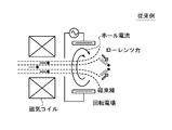
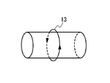
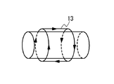
- FIG. 3 in the Lissajous accelerator, plasma is rotated in the circumferential direction using a rotating electric field (or rotating magnetic field). Then, the plasma is accelerated by the interaction (Lorentz force) between the plasma rotating in the circumferential direction (Hall current) and the divergent magnetic field of the magnetic coil.
- the plasma acceleration device includes a magnetic field generator, a supply path disposed so as to cross a central region of the magnetic field generator, a cathode disposed on the downstream side of the magnetic field generator, and the cathode And an anode disposed on the upstream side, and a voltage applying device that applies a voltage between the cathode and the anode.
- Plasma is supplied from the upstream side toward the downstream side by the supply path.
- the magnetic field generator generates an axial magnetic field in the central region of the magnetic field generator, and generates a magnetic field including a radial magnetic field downstream of the magnetic field generator.
- the voltage application device generates an electric field between the cathode and the anode.
- the plasma supplied through the supply path is accelerated by a Hall electric field generated by the interaction of electrons emitted from the cathode, the radial magnetic field, and the electric field.
- the plasma acceleration method in the present invention is a method of accelerating plasma using a plasma accelerator.
- the plasma accelerator includes a magnetic field generator, a supply path disposed so as to cross a central region of the magnetic field generator, a cathode disposed on the downstream side of the magnetic field generator, and an upstream side of the cathode An anode disposed on the cathode, and a voltage applying device that applies a voltage between the cathode and the anode.
- Plasma is supplied from the upstream side toward the downstream side by the supply path.
- the plasma acceleration method includes a step of emitting electrons from the cathode, a step of capturing the electrons in a radial magnetic field generated by the magnetic field generator to form a hole current, and the hole current and the diameter.
- the above configuration provides a plasma acceleration device and a plasma acceleration method capable of obtaining a large thrust.
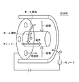
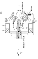
- FIG. 1 is a diagram schematically showing a configuration of a hole thruster which is a conventional plasma accelerator.
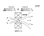
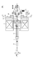
- FIG. 2 is a diagram schematically showing a configuration of a magnetic nozzle which is a conventional plasma accelerator.
- FIG. 3 is a diagram schematically showing a configuration of a Lissajous acceleration device which is a conventional plasma acceleration device.
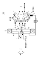
- FIG. 4 is a diagram schematically showing the configuration of the plasma acceleration apparatus of the first embodiment.
- FIG. 5 is a diagram schematically showing the configuration of the plasma accelerator of the second embodiment.
- FIG. 6 is a diagram schematically showing the configuration of the plasma accelerator of the third embodiment.
- FIG. 7A is a diagram illustrating a first example of a plasma generating antenna.
- FIG. 7B is a diagram illustrating a second example of the plasma generating antenna.
- FIG. 7C is a diagram illustrating a third example of the plasma generating antenna.
- FIG. 7D is a diagram illustrating a fourth example of the plasma generating antenna.
- FIG. 7E is a diagram illustrating a fifth example of the plasma generating antenna.
- FIG. 7F is a diagram illustrating a sixth example of the plasma generating antenna.
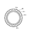
- FIG. 8 is a cross-sectional view taken along the line AA in FIG. 6 and shows the arrangement of the divided pieces of the magnetic flux collector (second ferromagnetic material).
- FIG. 9 is a diagram illustrating a modified example of the position of the anode in the plasma accelerator of the third embodiment.
- the coordinate system is defined with reference to FIGS. 4, 5, and 6.
- the X direction is the direction of the X axis that is the central axis of the plasma accelerators 100, 200, and 300, and the + X direction means the backward direction of the plasma accelerators 100, 200, and 300, that is, the direction in which plasma is emitted.
- the ⁇ direction is the rotation direction around the X axis, and the + ⁇ direction means clockwise when viewed in the + X direction.
- the + X direction side is defined as “downstream side”, and the ⁇ X direction side is defined as “upstream side”.
- electrodeless plasma is defined as plasma generated by an electrodeless plasma generator.
- An “electrodeless plasma generation apparatus” is defined as a plasma generation apparatus in which an electrode and plasma are not in direct contact in the plasma generation process.
- FIG. 4 is a diagram schematically showing the configuration of the plasma acceleration apparatus of the first embodiment.
- the plasma accelerator 100 includes a plasma supply path 1, a magnetic coil 2, a cathode 3, an anode 4, and a voltage application device 5.
- the supply path 1 is a flow path for supplying plasma from the upstream side toward the downstream side.
- the upstream portion of the supply path 1 is constituted by, for example, a plasma supply pipe.
- the plasma supply tube is preferably a tube having a circular cross section.
- the downstream part of the supply path 1 is, for example, a space downstream of the plasma supply pipe.
- the plasma supplied via the supply path 1 is preferably electrodeless plasma generated by an electrodeless plasma generator.
- the magnetic coil 2 is disposed so as to surround the supply path 1. In other words, the supply path 1 crosses the central region Q of the magnetic coil 2.
- the central region Q of the magnetic coil 2 means a hollow region inside the inner diameter of the magnetic coil 2 (region surrounded by a broken line in FIG. 4).
- the central axis S of the magnetic coil is preferably coincident with the X axis.
- Magnetic coil 2 the central region Q of the coil, generates an axial magnetic field B x along the center axis S of the coil. It said axial magnetic field B x is the downstream side is diffused in a direction away from the central axis S. Diffused field includes radial magnetic field B d extending radially from the central axis S.
- the magnetic coil 2 it is possible to replace the first ferromagnetic body to produce an axial magnetic field B x and the radial direction magnetic field B d (not shown).
- the magnetic coil 2 and the first ferromagnetic body are magnetic field generators (axial magnetic field and radial magnetic field generator) that generate magnetic fields (axial magnetic field and radial magnetic field).
- the cathode 3 emits electrons.
- the cathode 3 is preferably a hollow cathode with fine pores.
- the anode 4 is disposed on the upstream side of the cathode 3. Voltage applying device 5, the cathode 3 and by applying the applied voltage V ac between the anode 4 and generates an electric field E x in the X-axis direction.
- an axial magnetic field B x is generated in the central region Q of the magnetic coil 2.
- a magnetic field including the radial magnetic field B d is generated on the downstream side of the magnetic coil 2.
- the axial magnetic field B x and the radial magnetic field B d may be generated by the first ferromagnet.
- the electric field E x in the X-axis direction is generated. Further, electrons e ⁇ are emitted from the cathode 3.
- Plasma is supplied via the supply path 1.
- the plasma (particularly positive ion P + ) supplied via the supply path 1 is obtained by the mutual relationship between the electron e ⁇ emitted from the cathode 3, the radial magnetic field B d, and the electric field E x. It is accelerated toward the downstream side by the Hall electric field E generated by the action.
- the outline of the acceleration mechanism by the Hall electric field E is as follows (4a) (4b) (4c).
- Electrons e ⁇ are emitted from the cathode 3 toward the region where the radial magnetic field B d and the electric field E x exist. The emitted electrons e ⁇ are captured by the radial magnetic field B d and move in a hole motion.
- a hole current is generated by the hole motion of the electron e ⁇ .
- the electrons e ⁇ emitted from the cathode 3 generate a hole current (for example, a current that rotates around the central axis S in the ⁇ direction) due to the interaction between the radial magnetic field B d and the electric field E x.
- hole electric field E is generated by the interaction of the hole current and the radial direction magnetic field B d (Hall effect).
- (4c) In the presence of the hall electric field E, plasma is supplied through the supply path 1.
- the plasma contains ionized cations P + and electrons e ⁇ . A part of the ionized electrons e ⁇ is captured by the anode 4.
- the ionized electrons e ⁇ are trapped by the radial magnetic field B d and enhance the hole current.
- the ionized positive ion P + is accelerated toward the downstream side by the Hall electric field E.
- the electric field E x in the X-axis direction is generated between the cathode 3 and the anode 4 also assists accelerating the plasma (cations P +).
- a part of the accelerated cation P + collides with a part of the electron e ⁇ emitted from the cathode, and is discharged to the downstream side of the plasma accelerator 100 in an electrically neutralized state.
- the A part of the accelerated positive ion P + attracts a part of the electron e ⁇ emitted from the cathode by the Coulomb force, and is emitted to the downstream side of the plasma accelerator 100 together with the electron e ⁇ .
- the plasma accelerator 100 according to the first embodiment does not use a rotating electric field or a rotating magnetic field like the Lissajous accelerator. Therefore, even when electrodeless plasma having a high density is supplied via the supply path 1, it is possible to effectively accelerate the electrodeless plasma. For this reason, the plasma acceleration apparatus 100 in the first embodiment can increase the thrust.
- the plasma acceleration apparatus in the present embodiment it is possible to overcome the following problems when accelerating the electrodeless plasma.
- the Lissajous accelerator it is necessary to sufficiently penetrate the applied electric field or magnetic field into the plasma in the process of inducing the hole current.
- the electric or magnetic field is applied only to the surface of the plasma, does not penetrate to the center of the plasma, and cannot induce a hole current. Therefore, in the Lissajous acceleration device, the plasma density cannot be increased, and as a result, a large thrust cannot be obtained.
- FIG. 5 is a diagram schematically showing the configuration of the plasma accelerator of the second embodiment.
- the plasma accelerator 200 according to the second embodiment is different from the plasma accelerator 100 according to the first embodiment in that it includes a second ferromagnetic body 6 (a magnetic circuit that forms a magnetic flux path).
- the specific position of the second ferromagnetic body 6 disposed on the downstream side of the magnetic coil 2 (or the first ferromagnetic body) is arbitrary.
- the 2nd ferromagnetic body 6 is arrange
- adjacent means that the magnetic coil 2 (or first ferromagnet) and the second ferromagnet 6 are in contact with each other (the distance is zero) from the magnetic coil 2 (or first ferromagnet).
- second ferromagnetic body 6 means a range up to a state where they are separated by 100 mm.
- the second ferromagnetic body 6 is preferably arranged in a ring (ring shape) around the supply path 1.
- the second ferromagnet 6 collects the magnetic flux on the downstream side of the magnetic coil 2 (or the first ferromagnet) and forms a strong radial magnetic field Bd . For this reason, compared with the first embodiment, the formed hole current and the hole electric field E are enhanced. As a result, plasma acceleration by the Hall electric field E is enhanced.
- this embodiment can further increase the thrust as compared with the plasma accelerator of the first embodiment.
- FIG. 6 is a diagram schematically showing the configuration of the plasma accelerator of the third embodiment.
- Plasma accelerating device 300 includes plasma supply path 1, magnetic coil 2 (or first ferromagnet), cathode 3, anode 4, voltage application device 5, and second ferromagnet 6 (magnetic flux). Magnetic circuit forming a passage).
- the supply path 1 is a flow path for supplying plasma from the upstream side toward the downstream side.
- the upstream portion of the supply path 1 is constituted by, for example, an upstream pipe 11.
- the downstream part of the supply path 1 is comprised by the downstream pipe 12, for example.
- the upstream pipe 11 and the downstream pipe 12 are preferably pipes having a circular cross section.
- a propellant for example, argon gas, xenon gas
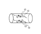
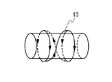
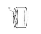
- an antenna 13 for converting the propellant into plasma is disposed around the upstream pipe 11.
- the antenna 13 is, for example, a helical antenna. An electric field is induced when a high-frequency current is passed through the helical antenna.
- Helicon wave is generated by the interaction of the axial magnetic field B x and the electric field created by the magnetic coil 2 below.
- the antenna 13 is preferably inserted into the magnetic coil 2.
- the antenna 13 overlap in the direction of the supply path 1 (preferably, the direction of the supply path 1 and the direction of the X axis coincide). It is preferable.
- Helicon waves act on the propellant to generate helicon plasma.
- the generated helicon plasma is supplied to the downstream pipe 12.
- the upstream pipe 11 and the downstream pipe 12 are preferably formed of an insulating material.
- the insulating material for example, Photovale (registered trademark) can be used.
- the inner diameter d1 of the upstream pipe 11 is preferably 20 mm or more and 100 mm or less in order to cause the electric field and the axial magnetic field B x to act and ionize the propellant.
- FIG. 7A shows a first example of an antenna.
- the antenna of the first example is a loop antenna.
- FIG. 7B shows a second example of the antenna.
- the antenna of the second example is a Boswell antenna.
- FIG. 7C shows a third example of the antenna.
- the antenna of the third example is a saddle type antenna.
- FIG. 7D shows a fourth example of the antenna.
- the antenna of the fourth example is a Nagoya type 3 type antenna.
- a plurality of modes can be selected by changing the phase between the four coil currents.
- FIG. 7E shows a fifth example of the antenna.
- the antenna of the fifth example is a helical antenna.
- FIG. 7F shows a sixth example of the antenna.
- the antenna of the sixth example is a spiral antenna.
- the antenna can be applied to a large-diameter plasma supply path.
- the magnetic coil 2 is disposed so as to surround the supply path 1. In other words, the supply path 1 crosses the central region Q of the magnetic coil 2.
- the central area Q of the magnetic coil 2 means a hollow area inside the inner diameter of the magnetic coil 2 (area surrounded by a broken line in FIG. 6).
- the central axis S of the magnetic coil 2 is preferably coincident with the X axis.
- the inner peripheral surface of the magnetic coil 2 is disposed to face the outer peripheral surface of the upstream pipe 11 and / or the downstream pipe 12.
- the magnetic coil 2 is supported by the support member 21. Magnetic coil 2, the central region Q of the coil to form an axial magnetic field B x along the center axis S.
- axial magnetic field B x is a magnetic coil 2 and the downstream side of the second ferromagnetic body 6, is spread in a direction away from the central axis S. That is, the magnetic coil 2, as well as providing an axial magnetic field B x for plasma propellant, to provide a radial magnetic field B d for forming holes field.
- the inner diameter d2 of the downstream pipe 12 is preferably larger than the inner diameter d1 of the upstream pipe 11.
- the magnetic coil 2 it is possible to replace the first ferromagnetic body to produce an axial magnetic field B x and the radial direction magnetic field B d (not shown).
- the second ferromagnetic body 6 is disposed on the downstream side of the magnetic coil 2 (or the first ferromagnetic body).
- the second ferromagnetic body 6 is preferably disposed around the downstream pipe 12 (arranged so as to surround the downstream pipe 12).
- the second ferromagnetic body 6 is preferably disposed on the downstream side of the magnetic coil 2 (or the first ferromagnetic body) and adjacent to the magnetic coil.
- the second ferromagnetic body 6 is preferably arranged in a ring (ring shape) around the supply path 1.
- the second ferromagnet 6 collects magnetic fluxes downstream of the magnetic coil 2 (or the first ferromagnet) and the second ferromagnet 6 to form a strong radial magnetic field Bd . That is, it can be said that the second ferromagnetic body 6 is a magnetic flux collector. For this reason, compared with the first embodiment, the formed hole current and the hole electric field E are enhanced. As a result, plasma acceleration by the Hall electric field E is enhanced. As shown in FIG. 8 (AA arrow cross-sectional view of FIG. 6), the second ferromagnetic body 6 is composed of a plurality of divided pieces 6-1, 6-2,. It may be configured.
- the plurality of divided pieces 6-1, 6-2,..., 6 -n are arranged at equal intervals around the supply path 1.
- the number of divided pieces is 16, but is not limited to this example.
- the second ferromagnetic body 6 is attached to the yoke 60.
- the yoke 60 is attached to the support member 21 that supports the magnetic coil 2 (or the first ferromagnetic body).
- the material of the yoke 60 is, for example, soft iron.
- the yoke 60 includes an extending portion 61 that extends outward (radially outward) from the second ferromagnetic body 6.
- the shape of the extending portion 61 is, for example, a flat ring shape. By providing the extending portion 61, the magnetic flux on the downstream side of the magnetic coil 2 (or the first ferromagnetic body) and the second ferromagnetic body 6 can be collected more strongly.
- the material of the extension part 61 is soft iron, for example.
- the magnetic coil 2 (or first ferromagnet) and the second ferromagnet 6 (magnetic circuit) provide a downstream side of the magnetic coil 2 (or the first ferromagnet) and the second ferromagnet 6 (more specifically, Is a region (cusp magnetic field) in which the magnetic flux density is sparse in the center of the circular current path of the Hall current.
- the cathode 3 emits electrons.
- the cathode 3 is preferably a hollow cathode with fine pores.
- the hollow cathode may include an insert that is a chemical substance. When this insert is heated to a high temperature by a heater, the insert emits thermoelectrons. The emitted thermoelectrons collide with the working gas supplied into the hollow cathode, and generate plasma in the hollow cathode. When a positive electrode is disposed at the cathode outlet, electrons are emitted from the plasma to the outside of the cathode.
- the anode 4 is disposed on the upstream side of the cathode 3.
- the anode 4 may be disposed on the upstream side of the downstream end of the magnetic coil 2 (or the first ferromagnetic body). Further, the anode 4 may be disposed on the downstream side of the upstream end of the magnetic coil 2 (or the first ferromagnetic body).
- an upstream end portion of the downstream pipe 12 is preferable inside the downstream pipe 12. That is, it is preferable to install the anode 4 in the inner diameter enlarged portion between the upstream pipe 11 and the downstream pipe 12.
- the position where the anode 4 is provided is not limited to the above example.
- the anode 4 may be provided at any position in the downstream pipe 12. For example, as shown in FIG. 9, it may be provided at the downstream end of the downstream pipe 12.
- the material of the anode 4 is, for example, copper.
- an axial magnetic field B x is generated in the central region Q of the magnetic coil 2. Further, by activating the magnetic coil 2, on the downstream side of the magnetic coil 2 and the second ferromagnetic body 6, a magnetic field comprising a radial magnetic field B d is generated. Alternatively, the axial magnetic field B x and the radial magnetic field B d may be generated by the first ferromagnet and the second ferromagnet 6. (2) by applying a voltage by the voltage application device 5 and between the cathode 3 and the anode 4, the electric field E x in the X-axis direction is generated.
- a propellant for example, argon gas, xenon gas
- a propellant is supplied to the upstream pipe 11.
- An electric field is induced by applying a high-frequency current to the antenna 13. The interaction of the axial magnetic field B x and the electric field created by the magnetic coil 2 (or the first ferromagnetic body), helicon wave is generated.
- the propellant is turned into plasma by the helicon wave acting on the propellant supplied to the upstream pipe 11.
- the propellant converted into plasma is supplied from the upstream pipe 11 toward the downstream pipe 12 and is further released to the downstream side of the downstream pipe 12.
- the emitted electrodeless plasma (the electrodeless plasma supplied via the supply path 1, in particular, the cation P + constituting the electrodeless plasma) is emitted from the cathode 3 by the electron e ⁇ said radial magnetic field B d, by the Hall electric field E generated by the interaction between the electric field E x, are accelerated toward the downstream side.
- the outline of the acceleration mechanism by the Hall electric field E is as follows (7a) (7b) (7c).
- Electrons e ⁇ are emitted from the cathode 3 toward the region where the radial magnetic field B d and the electric field E x exist. The emitted electrons e ⁇ are captured by the radial magnetic field B d and move in a hole motion.
- a hole current (for example, a current rotating around the central axis S in the ⁇ direction) is generated by the hole motion of the electron e ⁇ .
- the electrons e ⁇ emitted from the cathode 3 generate a hole current by the interaction between the radial magnetic field B d and the electric field E x .
- holes electric field E is generated by the interaction of the hole current and the radial direction magnetic field B d (Hall effect).
- electrodeless plasma is supplied via the supply path 1.
- the electrodeless plasma includes ionized cations P + and electrons e ⁇ . Some of the ionized electrons e ⁇ are trapped by the anode.
- the ionized positive ion P + is accelerated toward the downstream side by the Hall electric field E.
- the electric field E x in the X-axis direction is generated between the cathode 3 and the anode 4 also assists accelerating the plasma (cations P +).
- a part of the accelerated positive ion P + collides with an electron e ⁇ that forms a hole current, and is discharged to the downstream side of the plasma accelerator 300 in an electrically neutralized state.
- a part of the accelerated positive ion P + attracts an electron e ⁇ that forms a hole current by the Coulomb force, and is released to the downstream side of the plasma accelerator 300 with the electron e ⁇ .
- the positive ion P + passes through a region (cusp magnetic field) in which the magnetic flux density is sparse, so that it is released from restraint by the magnetic flux. For this reason, the positive ions P + are favorably diffused and emitted toward the downstream side of the plasma accelerator 300.
- the present embodiment has the following effects.
- Third, the magnetic coil 2 (or the first ferromagnetic body) is to form the axial magnetic field B x for plasma generation, to form a radial magnetic field B d for generating the hole current. That is, since the generation of the plasma and the acceleration of the plasma are performed using one magnetic coil 2 (or the first ferromagnet), the entire apparatus can be made compact.
Abstract
供給路(1)から供給されるプラズマを、カソード(3)から放出される電子(e-)と、径方向磁場(Bd)と、電場(Ex)との相互作用によって生成されるホール電場(E)によって加速させる。
Description
本発明は、プラズマ加速装置及びプラズマ加速方法に関する。
宇宙で使用される推進装置として、プラズマを加速して後方に放出し、その反力で推力を得る装置が知られている。特許文献1には、アーク放電により形成されたプラズマを、ノズルから排出することで推力を得る電気推進機が開示されている。特許文献2には、放電により生成された荷電粒子を、スクリーン電極及び加速電極を用いて、選択的に加速するイオンエンジンが開示されている。
また、推進装置として、ホール電流を利用したホールスラスタが知られている。図1に示されるように、ホールスラスタでは、カソードから供給される電子が、電場と磁場との相互作用により周方向にホール運動を行う(ホール電流を形成する)。このホール運動を行う電子が、推進剤を電離させて、プラズマを生成する。前記プラズマは電界により加速され、後方に放出される。
さらに、無電極プラズマ生成装置により生成された無電極プラズマを加速させる装置として、磁気ノズルによる加速装置、及び、回転電場又は回転磁場による加速装置(リサージュ加速装置)が知られている。ここで、無電極プラズマ生成装置は、プラズマの生成過程において、電極とプラズマとが直接接触することのないプラズマ生成装置と定義される。図2に示されるように、磁気ノズルでは、磁気コイルを用いて、プラズマを加速する。磁気コイルは、プラズマの熱エネルギーを、ノズル後方に向かう運動エネルギーに変換する。図3に示されるように、リサージュ加速装置では、回転電場(又は回転磁場)を用いて、プラズマを周方向に回転させる。そして、周方向に回転するプラズマ(ホール電流)と、磁気コイルの発散磁場との相互作用(ローレンツ力)により、プラズマを加速する。
本発明におけるプラズマ加速装置は、磁場生成体と、前記磁場生成体の中央領域を横断するように配置される供給路と、前記磁場生成体よりも下流側に配置されるカソードと、前記カソードよりも上流側に配置されるアノードと、前記カソードと前記アノードとの間に電圧を印加する電圧印加装置と、を備える。前記供給路によって、上流側から下流側に向けてプラズマが供給される。前記磁場生成体は、前記磁場生成体の前記中央領域に軸方向磁場を生成するとともに、前記磁場生成体よりも下流側に径方向磁場を含む磁場を生成する。前記電圧印加装置は、前記カソードと前記アノードとの間に、電場を生成する。前記供給路を介して供給される前記プラズマは、前記カソードから放出される電子と、前記径方向磁場と、前記電場との相互作用によって生成されるホール電場によって加速される。
本発明におけるプラズマ加速方法は、プラズマ加速装置を用いてプラズマを加速する方法である。プラズマ加速装置は、磁場生成体と、前記磁場生成体の中央領域を横断するように配置される供給路と、前記磁場生成体よりも下流側に配置されるカソードと、前記カソードよりも上流側に配置されるアノードと、前記カソードと前記アノードとの間に電圧を印加する電圧印加装置と、を備える。前記供給路によって、上流側から下流側に向けてプラズマが供給される。また、プラズマ加速方法は、電子を前記カソードから放出する工程と、前記磁場生成体により生成される径方向磁場に前記電子を捕捉させて、ホール電流を形成する工程と、前記ホール電流と前記径方向磁場との相互作用により生成されるホール電場によって、前記供給路を介して供給される前記プラズマを加速する工程を備える。
上記構成によって、大きな推力を得ることが可能なプラズマ加速装置及びプラズマ加速方法が提供される。
この発明の目的と利益とは以下の説明と添付図面とによって容易に確認することができる。
添付の図面は、実施形態の説明を助けるために本明細書に組み込まれる。図面は、本発明を、図示された例および説明された例に限定するものとして解釈されるべきではない。
図1は、従来のプラズマ加速装置であるホールスラスタの構成を模式的に示す図である。
図2は、従来のプラズマ加速装置である磁気ノズルの構成を模式的に示す図である。
図3は、従来のプラズマ加速装置であるリサージュ加速装置の構成を模式的に示す図である。
図4は、第1の実施形態のプラズマ加速装置の構成を模式的に示す図である。
図5は、第2の実施形態のプラズマ加速装置の構成を模式的に示す図である。
図6は、第3の実施形態のプラズマ加速装置の構成を模式的に示す図である。
図7Aは、プラズマ生成アンテナの第1例を示す図である。
図7Bは、プラズマ生成アンテナの第2例を示す図である。
図7Cは、プラズマ生成アンテナの第3例を示す図である。
図7Dは、プラズマ生成アンテナの第4例を示す図である。
図7Eは、プラズマ生成アンテナの第5例を示す図である。
図7Fは、プラズマ生成アンテナの第6例を示す図である。
図8は、図6のA-A矢視断面図であり、磁束収集体(第2強磁性体)の分割片の配置を示す図である。
図9は、第3の実施形態のプラズマ加速装置において、アノードの位置の変形例を示す図である。
以下、本発明の実施の形態に係るプラズマ加速装置、及び、プラズマ加速方法に関して、添付図面を参照して説明する。
以下の詳細な説明においては、実施形態の包括的な理解を提供するために、説明の目的で多くの詳細な特定事項が開示される。しかし、一又は複数の実施形態は、これらの詳細な特定事項なしで実行可能であることが明らかである。また、周知の構造又は周知の装置は、図面を簡潔なものとするために概要のみが示されている。
以下の詳細な説明においては、実施形態の包括的な理解を提供するために、説明の目的で多くの詳細な特定事項が開示される。しかし、一又は複数の実施形態は、これらの詳細な特定事項なしで実行可能であることが明らかである。また、周知の構造又は周知の装置は、図面を簡潔なものとするために概要のみが示されている。
(座標系の定義)
図4、図5、及び、図6を参照して、座標系の定義を行う。X方向は、プラズマ加速装置100、200、300の中心軸であるX軸の方向であり、+X方向は、プラズマ加速装置100、200、300の後ろ方向、すなわち、プラズマが放出される方向を意味する。φ方向は、前記X軸まわりの回転方向であり、+φ方向は、+X方向にみて時計回りを意味する。
図4、図5、及び、図6を参照して、座標系の定義を行う。X方向は、プラズマ加速装置100、200、300の中心軸であるX軸の方向であり、+X方向は、プラズマ加速装置100、200、300の後ろ方向、すなわち、プラズマが放出される方向を意味する。φ方向は、前記X軸まわりの回転方向であり、+φ方向は、+X方向にみて時計回りを意味する。
(重要な用語の定義)
本実施の形態において、+X方向の側を「下流側」と定義し、-X方向の側を「上流側」と定義する。また、「無電極プラズマ」は、無電極プラズマ生成装置で生成されたプラズマと定義する。「無電極プラズマ生成装置」は、プラズマの生成過程において、電極とプラズマとが直接接触することのないプラズマ生成装置と定義する。
本実施の形態において、+X方向の側を「下流側」と定義し、-X方向の側を「上流側」と定義する。また、「無電極プラズマ」は、無電極プラズマ生成装置で生成されたプラズマと定義する。「無電極プラズマ生成装置」は、プラズマの生成過程において、電極とプラズマとが直接接触することのないプラズマ生成装置と定義する。
(第1の実施形態)
図4を参照して、第1の実施形態に係るプラズマ加速装置について説明する。図4は、第1の実施形態のプラズマ加速装置の構成を模式的に示す図である。
図4を参照して、第1の実施形態に係るプラズマ加速装置について説明する。図4は、第1の実施形態のプラズマ加速装置の構成を模式的に示す図である。
1.プラズマ加速装置100の構成
プラズマ加速装置100は、プラズマの供給路1、磁気コイル2、カソード3、アノード4、電圧印加装置5を備える。供給路1は、上流側から下流側に向かってプラズマを供給する流路である。供給路1の上流部は、例えば、プラズマ供給管によって構成される。なお、プラズマ供給管は、断面円形の管であることが好ましい。供給路1の下流部は、例えば、プラズマ供給管よりも下流側の空間である。また、供給路1を介して供給されるプラズマは、好ましくは、無電極プラズマ生成装置によって生成される無電極プラズマである。磁気コイル2は、供給路1を囲むように配置される。換言すれば、供給路1は、磁気コイル2の中央領域Qを横断する。ここで、磁気コイル2の中央領域Qとは、磁気コイル2の内径の内側の空洞領域(図4において破線で囲まれた領域)を意味する。なお、磁気コイルの中心軸Sは、X軸と一致することが好ましい。磁気コイル2は、コイルの中央領域Qに、コイルの中心軸Sに沿う軸方向磁場Bxを生成する。前記軸方向磁場Bxは、下流側で、前記中心軸Sから遠ざかる方向に拡散される。拡散された磁場は、前記中心軸Sから放射状に拡がる径方向磁場Bdを含む。なお、磁気コイル2は、軸方向磁場Bx及び径方向磁場Bdを生成する第1強磁性体(図示せず)に置換することが可能である。磁気コイル2と第1強磁性体とは、磁場(軸方向磁場及び径方向磁場)を生成する磁場生成体(軸方向磁場及び径方向磁場生成体)であるといえる。カソード3は、電子を放出する。カソード3は、好ましくは、微細孔を備えたホローカソードである。アノード4は、カソード3の上流側に配置される。電圧印加装置5は、カソード3とアノード4との間に印加電圧Vacを印加して、X軸方向の電場Exを生成する。
プラズマ加速装置100は、プラズマの供給路1、磁気コイル2、カソード3、アノード4、電圧印加装置5を備える。供給路1は、上流側から下流側に向かってプラズマを供給する流路である。供給路1の上流部は、例えば、プラズマ供給管によって構成される。なお、プラズマ供給管は、断面円形の管であることが好ましい。供給路1の下流部は、例えば、プラズマ供給管よりも下流側の空間である。また、供給路1を介して供給されるプラズマは、好ましくは、無電極プラズマ生成装置によって生成される無電極プラズマである。磁気コイル2は、供給路1を囲むように配置される。換言すれば、供給路1は、磁気コイル2の中央領域Qを横断する。ここで、磁気コイル2の中央領域Qとは、磁気コイル2の内径の内側の空洞領域(図4において破線で囲まれた領域)を意味する。なお、磁気コイルの中心軸Sは、X軸と一致することが好ましい。磁気コイル2は、コイルの中央領域Qに、コイルの中心軸Sに沿う軸方向磁場Bxを生成する。前記軸方向磁場Bxは、下流側で、前記中心軸Sから遠ざかる方向に拡散される。拡散された磁場は、前記中心軸Sから放射状に拡がる径方向磁場Bdを含む。なお、磁気コイル2は、軸方向磁場Bx及び径方向磁場Bdを生成する第1強磁性体(図示せず)に置換することが可能である。磁気コイル2と第1強磁性体とは、磁場(軸方向磁場及び径方向磁場)を生成する磁場生成体(軸方向磁場及び径方向磁場生成体)であるといえる。カソード3は、電子を放出する。カソード3は、好ましくは、微細孔を備えたホローカソードである。アノード4は、カソード3の上流側に配置される。電圧印加装置5は、カソード3とアノード4との間に印加電圧Vacを印加して、X軸方向の電場Exを生成する。
2.プラズマ加速装置100の作動原理
次に、プラズマ加速装置100の作動原理について説明する。
(1)磁気コイル2を作動させることにより、磁気コイル2の中央領域Qには、軸方向磁場Bxが生成される。また、磁気コイル2を作動させることにより、磁気コイル2の下流側には、径方向磁場Bdを含む磁場が生成される。代替的に、軸方向磁場Bx及び径方向磁場Bdは、第1強磁性体によって生成されてもよい。
(2)電圧印加装置5による電圧印加により、カソード3とアノード4との間には、X軸方向の電場Exが生成される。また、カソード3からは、電子e-が放出される。
(3)供給路1を介してプラズマが供給される。
(4)供給路1を介して供給されるプラズマ(特に、陽イオンP+)は、カソード3から放出される前記電子e-と、前記径方向磁場Bdと、前記電場Exとの相互作用により生成されるホール電場Eによって、下流側に向かって加速される。なお、ホール電場Eによる加速のメカニズムの概要は下記(4a)(4b)(4c)のとおりである。
(4a)径方向磁場Bd及び電場Exの存在する領域に向けて、カソード3から電子e-が放出される。放出された電子e-は、径方向磁場Bdに捕捉されて、ホール運動する。電子e-のホール運動により、ホール電流が生成される。換言すれば、カソード3から放出される電子e-は、径方向磁場Bdと電場Exとの相互作用により、ホール電流(例えば、中心軸Sのまわりを-φ方向に回転する電流)を生成する。
(4b)ホール電流と径方向磁場Bdとの相互作用(ホール効果)によりホール電場Eが生成される。
(4c)ホール電場Eの存在下において、供給路1を介してプラズマが供給される。前記プラズマは、電離した陽イオンP+と電子e-を含む。電離した電子e-の一部は、アノード4に捕捉される。電離した電子e-の一部は、径方向磁場Bdに捕捉されて、前記ホール電流を強化する。電離した陽イオンP+は、ホール電場Eにより、下流側に向けて加速される。なお、カソード3とアノード4との間に生成されるX軸方向の電場Exも、プラズマ(陽イオンP+)の加速を補助する。
(5)加速された陽イオンP+の一部は、カソードから放出される電子e-の一部と衝突し、電気的に中和された状態で、プラズマ加速装置100の下流側に放出される。加速された陽イオンP+の一部は、クーロン力により、カソードから放出される電子e-の一部を引き付け、当該電子e-を伴って、プラズマ加速装置100の下流側に放出される。
3.効果
プラズマ加速装置100の下流側に放出される粒子(陽イオンP+と電子e-との衝突により生成される粒子)又はプラズマは、電気的に中性の粒子又は電気的に中性のプラズマ(電子e-とともに放出される陽イオンP+)である。よって、プラズマ加速装置100は、電気的に概ね中性の状態が維持されるため、空間電荷制限(ある電極間に電位差を加えてイオンを加速する場合、流すことのできる電流密度の上限)の影響を受けない。このため、第1の実施形態におけるプラズマ加速装置100は、大推力化が可能である。
プラズマ加速装置100の下流側に放出される粒子(陽イオンP+と電子e-との衝突により生成される粒子)又はプラズマは、電気的に中性の粒子又は電気的に中性のプラズマ(電子e-とともに放出される陽イオンP+)である。よって、プラズマ加速装置100は、電気的に概ね中性の状態が維持されるため、空間電荷制限(ある電極間に電位差を加えてイオンを加速する場合、流すことのできる電流密度の上限)の影響を受けない。このため、第1の実施形態におけるプラズマ加速装置100は、大推力化が可能である。
また、第1の実施形態におけるプラズマ加速装置100は、リサージュ加速装置のように、回転電場又は回転磁場を用いるものではない。よって、密度の高い無電極プラズマを供給路1を介して供給する場合であっても、無電極プラズマを有効に加速することが可能である。このため、第1の実施形態におけるプラズマ加速装置100は、大推力化が可能である。
また、本実施形態におけるプラズマ加速装置によれば、無電極プラズマを加速する際の次のような課題を克服することが可能である。
(無電極プラズマを加速する際の課題)
まず、磁気ノズルを用いて、無電極プラズマを加速する際の課題について説明する。無電極プラズマは、生成時に、数eV~10eVの電子温度しか有していないため、電子温度すなわち熱エネルギーを運動エネルギーに変換しても、高い比推力が得られない。このため、無電極プラズマを加熱して、電子温度を上昇させることが考えられるが、エネルギー効率の観点から好ましくない。また、プラズマを加熱する際にプラズマを閉じ込めるために強力な磁場が必要になるとの課題もある。続いて、リサージュ加速装置を用いて、無電極プラズマを加速する際の課題について説明する。リサージュ加速装置においては、ホール電流を誘起する過程において、印加電場又は磁場をプラズマ中に十分浸透させる必要がある。しかし、プラズマの密度が高い場合、電場又は磁場は、プラズマの表面のみに印加され、プラズマの中心まで浸透せず、ホール電流を誘起することができない。よって、リサージュ加速装置では、プラズマ密度を高くすることができず、結果として、大きな推力を得ることができない。
まず、磁気ノズルを用いて、無電極プラズマを加速する際の課題について説明する。無電極プラズマは、生成時に、数eV~10eVの電子温度しか有していないため、電子温度すなわち熱エネルギーを運動エネルギーに変換しても、高い比推力が得られない。このため、無電極プラズマを加熱して、電子温度を上昇させることが考えられるが、エネルギー効率の観点から好ましくない。また、プラズマを加熱する際にプラズマを閉じ込めるために強力な磁場が必要になるとの課題もある。続いて、リサージュ加速装置を用いて、無電極プラズマを加速する際の課題について説明する。リサージュ加速装置においては、ホール電流を誘起する過程において、印加電場又は磁場をプラズマ中に十分浸透させる必要がある。しかし、プラズマの密度が高い場合、電場又は磁場は、プラズマの表面のみに印加され、プラズマの中心まで浸透せず、ホール電流を誘起することができない。よって、リサージュ加速装置では、プラズマ密度を高くすることができず、結果として、大きな推力を得ることができない。
(第2の実施形態)
図5を参照して、第2の実施形態に係るプラズマ加速装置について説明する。図5は、第2の実施形態のプラズマ加速装置の構成を模式的に示す図である。
図5を参照して、第2の実施形態に係るプラズマ加速装置について説明する。図5は、第2の実施形態のプラズマ加速装置の構成を模式的に示す図である。
第2の実施形態において、第1の実施形態と同じ構成要素については、同じ図番を用いている。第2の実施形態のプラズマ加速装置200は、第2強磁性体6(磁束の通路を形成する磁気回路)を備える点で、第1の実施形態のプラズマ加速装置100と異なる。磁気コイル2(又は第1強磁性体)の下流側に配置される第2強磁性体6の具体的位置は任意である。なお、第2強磁性体6は、磁気コイル2(又は第1強磁性体)の下流側に、磁気コイル2(又は第1強磁性体)に隣接して配置されることが好ましい。ここで、「隣接」とは、磁気コイル2(又は第1強磁性体)と第2強磁性体6とが接する状態(距離がゼロの状態)から、磁気コイル2(又は第1強磁性体)と第2強磁性体6とが100mm離間する状態までの範囲を意味する。また、第2強磁性体6は、供給路1の周囲に、環状(リング状)に配置されることが好ましい。
第2強磁性体6は、磁気コイル2(又は第1強磁性体)の下流側の磁束を集め、強力な径方向磁場Bdを形成する。このため、第1の実施形態と比較して、形成されるホール電流、及び、ホール電場Eが強化される。その結果、ホール電場Eによるプラズマの加速が強化される。
本実施形態の作動原理は、第1の実施形態の作動原理と同様である。
本実施形態は、第1の実施形態と同様の効果を奏するのに加え、第1の実施形態のプラズマ加速装置と比較して、更なる大推力化が可能である。
(第3の実施形態)
図6を参照して、第3の実施形態に係るプラズマ加速装置について説明する。図6は、第3の実施形態のプラズマ加速装置の構成を模式的に示す図である。
図6を参照して、第3の実施形態に係るプラズマ加速装置について説明する。図6は、第3の実施形態のプラズマ加速装置の構成を模式的に示す図である。
第3の実施形態において、第1の実施形態と同じ構成要素については、同じ図番を用いている。
1.プラズマ加速装置300の構成
プラズマ加速装置300は、プラズマの供給路1、磁気コイル2(又は第1強磁性体)、カソード3、アノード4、電圧印加装置5、第2強磁性体6(磁束の通路を形成する磁気回路)を備える。
プラズマ加速装置300は、プラズマの供給路1、磁気コイル2(又は第1強磁性体)、カソード3、アノード4、電圧印加装置5、第2強磁性体6(磁束の通路を形成する磁気回路)を備える。
(プラズマの供給路1)
供給路1は、上流側から下流側に向かってプラズマを供給する流路である。供給路1の上流部は、例えば、上流管11によって構成される。供給路1の下流部は、例えば、下流管12によって構成される。上流管11及び下流管12は、断面円形の管であることが好ましい。上流管11の上流からは、推進剤(例えば、アルゴンガス、キセノンガス)が供給される。また、上流管11の周囲には、推進剤をプラズマ化するためのアンテナ13が配置されている。アンテナ13は、例えば、ヘリカルアンテナである。ヘリカルアンテナに高周波電流を流すと電場が誘起される。後述の磁気コイル2によって生成される軸方向磁場Bxと前記電場との相互作用によりヘリコン波が発生する。ヘリコン波を発生させるために、アンテナ13は、磁気コイル2の内部に挿入されていることが好ましい。換言すれば、前記磁気コイル2と前記アンテナ13とは、供給路1の方向(好ましくは、供給路1の方向とX軸の方向とは一致する。)に、少なくとも一部分がオーバーラップしていることが好ましい。ヘリコン波は、推進剤に作用して、ヘリコンプラズマを生成する。生成されたヘリコンプラズマは、下流管12に供給される。なお、上流管11及び下流管12は、絶縁材料で形成することが好ましい。絶縁材料としては、例えば、ホトベール(登録商標)を用いることができる。また、上流管11の内径d1は、電界及び軸方向磁場Bxを作用させて、推進剤を電離させるために、20mm以上、100mm以下であることが好ましい。
供給路1は、上流側から下流側に向かってプラズマを供給する流路である。供給路1の上流部は、例えば、上流管11によって構成される。供給路1の下流部は、例えば、下流管12によって構成される。上流管11及び下流管12は、断面円形の管であることが好ましい。上流管11の上流からは、推進剤(例えば、アルゴンガス、キセノンガス)が供給される。また、上流管11の周囲には、推進剤をプラズマ化するためのアンテナ13が配置されている。アンテナ13は、例えば、ヘリカルアンテナである。ヘリカルアンテナに高周波電流を流すと電場が誘起される。後述の磁気コイル2によって生成される軸方向磁場Bxと前記電場との相互作用によりヘリコン波が発生する。ヘリコン波を発生させるために、アンテナ13は、磁気コイル2の内部に挿入されていることが好ましい。換言すれば、前記磁気コイル2と前記アンテナ13とは、供給路1の方向(好ましくは、供給路1の方向とX軸の方向とは一致する。)に、少なくとも一部分がオーバーラップしていることが好ましい。ヘリコン波は、推進剤に作用して、ヘリコンプラズマを生成する。生成されたヘリコンプラズマは、下流管12に供給される。なお、上流管11及び下流管12は、絶縁材料で形成することが好ましい。絶縁材料としては、例えば、ホトベール(登録商標)を用いることができる。また、上流管11の内径d1は、電界及び軸方向磁場Bxを作用させて、推進剤を電離させるために、20mm以上、100mm以下であることが好ましい。
(アンテナ13の例)
アンテナ13としては、種々の形態のアンテナを採用し得る。図7Aは、アンテナの第1例を示す。第1例のアンテナは、ループアンテナである。図7Bは、アンテナの第2例を示す。第2例のアンテナは、Boswellアンテナである。図7Cは、アンテナの第3例を示す。第3例のアンテナは、サドル型アンテナである。図7Dは、アンテナの第4例を示す。第4例のアンテナは、名古屋タイプ3型アンテナである。当該アンテナでは、4個のコイル電流間の位相を変えることにより複数のモードの選択が可能である。図7Eは、アンテナの第5例を示す。第5例のアンテナは、ヘリカルアンテナである。図7Fは、アンテナの第6例を示す。第6例のアンテナは、スパイラル型アンテナである。当該アンテナは、大口径のプラズマ供給路に適用可能である。
アンテナ13としては、種々の形態のアンテナを採用し得る。図7Aは、アンテナの第1例を示す。第1例のアンテナは、ループアンテナである。図7Bは、アンテナの第2例を示す。第2例のアンテナは、Boswellアンテナである。図7Cは、アンテナの第3例を示す。第3例のアンテナは、サドル型アンテナである。図7Dは、アンテナの第4例を示す。第4例のアンテナは、名古屋タイプ3型アンテナである。当該アンテナでは、4個のコイル電流間の位相を変えることにより複数のモードの選択が可能である。図7Eは、アンテナの第5例を示す。第5例のアンテナは、ヘリカルアンテナである。図7Fは、アンテナの第6例を示す。第6例のアンテナは、スパイラル型アンテナである。当該アンテナは、大口径のプラズマ供給路に適用可能である。
(磁気コイル2)
磁気コイル2は、供給路1を囲むように配置される。換言すれば、供給路1は、磁気コイル2の中央領域Qを横断する。ここで、磁気コイル2の中央領域Qとは、磁気コイル2の内径の内側の空洞領域(図6において破線で囲まれた領域)を意味する。なお、磁気コイル2の中心軸Sは、X軸と一致することが好ましい。好ましくは、磁気コイル2の内周面は、上流管11及び/又は下流管12の外周面に対向配置される。磁気コイル2は、支持部材21によって支持される。磁気コイル2は、コイルの中央領域Qに、中心軸Sに沿う軸方向磁場Bxを形成する。前記軸方向磁場Bxは、磁気コイル2及び第2強磁性体6の下流側で、前記中心軸Sから遠ざかる方向に拡散される。すなわち、磁気コイル2は、推進剤をプラズマ化するための軸方向磁場Bxを提供するとともに、ホール電場を形成するための径方向磁場Bdを提供する。なお、磁気コイル2及び第2強磁性体6の下流側で磁場を拡散させるために、下流管12の内径d2は、上流管11の内径d1よりも大きいことが好ましい。なお、磁気コイル2は、軸方向磁場Bx及び径方向磁場Bdを生成する第1強磁性体(図示せず)に置換することが可能である。
磁気コイル2は、供給路1を囲むように配置される。換言すれば、供給路1は、磁気コイル2の中央領域Qを横断する。ここで、磁気コイル2の中央領域Qとは、磁気コイル2の内径の内側の空洞領域(図6において破線で囲まれた領域)を意味する。なお、磁気コイル2の中心軸Sは、X軸と一致することが好ましい。好ましくは、磁気コイル2の内周面は、上流管11及び/又は下流管12の外周面に対向配置される。磁気コイル2は、支持部材21によって支持される。磁気コイル2は、コイルの中央領域Qに、中心軸Sに沿う軸方向磁場Bxを形成する。前記軸方向磁場Bxは、磁気コイル2及び第2強磁性体6の下流側で、前記中心軸Sから遠ざかる方向に拡散される。すなわち、磁気コイル2は、推進剤をプラズマ化するための軸方向磁場Bxを提供するとともに、ホール電場を形成するための径方向磁場Bdを提供する。なお、磁気コイル2及び第2強磁性体6の下流側で磁場を拡散させるために、下流管12の内径d2は、上流管11の内径d1よりも大きいことが好ましい。なお、磁気コイル2は、軸方向磁場Bx及び径方向磁場Bdを生成する第1強磁性体(図示せず)に置換することが可能である。
(第2強磁性体6(磁束の通路を形成する磁気回路))
第2強磁性体6は、磁気コイル2(又は第1強磁性体)よりも下流側に配置される。第2強磁性体6は、下流管12の周囲に配置される(下流管12を囲むように配置される)ことが好ましい。第2強磁性体6は、磁気コイル2(又は第1強磁性体)の下流側に、磁気コイルに隣接して配置されることが好ましい。また、第2強磁性体6は、供給路1の周囲に、環状(リング状)に配置されることが好ましい。第2強磁性体6は、磁気コイル2(又は第1強磁性体)及び第2強磁性体6の下流側の磁束を集め、強力な径方向磁場Bdを形成する。すなわち、第2強磁性体6は、磁束収集体であるといえる。このため、第1の実施形態と比較して、形成されるホール電流、及び、ホール電場Eが強化される。その結果、ホール電場Eによるプラズマの加速が強化される。なお、図8(図6のA-A矢視断面図)に示されるように、第2強磁性体6は、複数の分割片6-1、6-2、・・・、6-nで構成されてもよい。そして、複数の分割片6-1、6-2、・・・、6-nは、供給路1の周囲に等間隔で配置される。図8の例では、分割片の個数は16であるが、この例に限定されない。第2強磁性体6を複数の分割片で構成することにより、第2強磁性体6の製造コストが低減される。なお、第2強磁性体6は、例えば、ネオジム磁石である。
第2強磁性体6は、磁気コイル2(又は第1強磁性体)よりも下流側に配置される。第2強磁性体6は、下流管12の周囲に配置される(下流管12を囲むように配置される)ことが好ましい。第2強磁性体6は、磁気コイル2(又は第1強磁性体)の下流側に、磁気コイルに隣接して配置されることが好ましい。また、第2強磁性体6は、供給路1の周囲に、環状(リング状)に配置されることが好ましい。第2強磁性体6は、磁気コイル2(又は第1強磁性体)及び第2強磁性体6の下流側の磁束を集め、強力な径方向磁場Bdを形成する。すなわち、第2強磁性体6は、磁束収集体であるといえる。このため、第1の実施形態と比較して、形成されるホール電流、及び、ホール電場Eが強化される。その結果、ホール電場Eによるプラズマの加速が強化される。なお、図8(図6のA-A矢視断面図)に示されるように、第2強磁性体6は、複数の分割片6-1、6-2、・・・、6-nで構成されてもよい。そして、複数の分割片6-1、6-2、・・・、6-nは、供給路1の周囲に等間隔で配置される。図8の例では、分割片の個数は16であるが、この例に限定されない。第2強磁性体6を複数の分割片で構成することにより、第2強磁性体6の製造コストが低減される。なお、第2強磁性体6は、例えば、ネオジム磁石である。
第2強磁性体6は、ヨーク60に取り付けられる。ヨーク60は、磁気コイル2(又は第1強磁性体)を支持する支持部材21に取り付けられる。ヨーク60の材質は、例えば、軟鉄である。前記ヨーク60は、第2強磁性体6よりも外方(径外方向)に延びる延設部61を備える。延設部61の形状は、例えば、平板リング形状である。延設部61を備えることにより、磁気コイル2(又は第1強磁性体)及び第2強磁性体6の下流側の磁束を、より強力に集めることができる。なお、延設部61の材質は、例えば、軟鉄である。
磁気コイル2(又は第1強磁性体)及び第2強磁性体6(磁気回路)によって、磁気コイル2(又は第1強磁性体)及び第2強磁性体6の下流側(より具体的には、ホール電流の円形の電流路の中央部)に、磁束密度が疎である領域(カスプ磁場)が形成される。
(カソード3)
カソード3は、電子を放出する。カソード3は、好ましくは、微細孔を備えたホローカソードである。ホローカソードは、化学物質であるインサートを備えていてもよい。このインサートをヒーターにより高温に熱すると,インサートは熱電子を放出する。放出された熱電子はホローカソード内に供給される作動ガスと電離衝突し、ホローカソード内でプラズマを発生させる。カソードの出口に、正電極を配置すると、プラズマの中から電子がカソード外に放出される。
カソード3は、電子を放出する。カソード3は、好ましくは、微細孔を備えたホローカソードである。ホローカソードは、化学物質であるインサートを備えていてもよい。このインサートをヒーターにより高温に熱すると,インサートは熱電子を放出する。放出された熱電子はホローカソード内に供給される作動ガスと電離衝突し、ホローカソード内でプラズマを発生させる。カソードの出口に、正電極を配置すると、プラズマの中から電子がカソード外に放出される。
(アノード4)
アノード4は、カソード3の上流側に配置される。前記アノード4は、前記磁気コイル2(又は第1強磁性体)の下流端よりも上流側に配置されてもよい。また、前記アノード4は、前記磁気コイル2(又は第1強磁性体)の上流端よりも下流側に配置されてもよい。なお、アノード4を配置する具体的な位置としては、下流管12の内側で下流管12の上流側端部が好ましい。すなわち、アノード4を、上流管11と下流管12との間の内径拡大部に設置することが好ましい。ただし、アノード4を設ける位置は、上記の例に限定されない。アノード4は、下流管12のどの位置に設けてもよい。例えば、図9に示されるように、下流管12の下流側端部に設けてもよい。また、アノード4の材質は、例えば、銅である。
アノード4は、カソード3の上流側に配置される。前記アノード4は、前記磁気コイル2(又は第1強磁性体)の下流端よりも上流側に配置されてもよい。また、前記アノード4は、前記磁気コイル2(又は第1強磁性体)の上流端よりも下流側に配置されてもよい。なお、アノード4を配置する具体的な位置としては、下流管12の内側で下流管12の上流側端部が好ましい。すなわち、アノード4を、上流管11と下流管12との間の内径拡大部に設置することが好ましい。ただし、アノード4を設ける位置は、上記の例に限定されない。アノード4は、下流管12のどの位置に設けてもよい。例えば、図9に示されるように、下流管12の下流側端部に設けてもよい。また、アノード4の材質は、例えば、銅である。
2.プラズマ加速装置300の作動原理
次に、プラズマ加速装置300の作動原理について説明する。
(1)磁気コイル2を作動させることにより、磁気コイル2の中央領域Qには、軸方向磁場Bxが生成される。また、磁気コイル2を作動させることにより、磁気コイル2及び第2強磁性体6の下流側には、径方向磁場Bdを含む磁場が生成される。代替的に、軸方向磁場Bx及び径方向磁場Bdは、第1強磁性体及び第2強磁性体6によって生成されてもよい。
(2)電圧印加装置5による電圧印加により、カソード3とアノード4との間には、X軸方向の電場Exが生成される。また、カソード3からは、電子e-が放出される。
(3)上流管11に推進剤(例えば、アルゴンガス、キセノンガス)が供給される。
(4)アンテナ13に高周波電流を印加することにより電場が誘起される。磁気コイル2(又は第1強磁性体)により生成される軸方向磁場Bxと前記電場との相互作用により、ヘリコン波が発生する。
(5)ヘリコン波が、上流管11に供給された推進剤に作用することにより、推進剤がプラズマ化される。
(6)プラズマ化した推進剤(無電極プラズマ)は、上流管11から下流管12に向けて供給され、さらに、下流管12の下流側に放出される。
(7)放出された無電極プラズマ(供給路1を介して供給される無電極プラズマ、特に、無電極プラズマを構成する陽イオンP+)は、カソード3から放出される前記電子e-と、前記径方向磁場Bdと、前記電場Exとの相互作用により生成されるホール電場Eによって、下流側に向かって加速される。なお、ホール電場Eによる加速のメカニズムの概要は下記(7a)(7b)(7c)のとおりである。
(7a)径方向磁場Bd及び電場Exの存在する領域に向けて、カソード3から電子e-が放出される。放出された電子e-は、径方向磁場Bdに捕捉されて、ホール運動する。電子e-のホール運動により、ホール電流(例えば、中心軸Sのまわりを-φ方向に回転する電流)が生成される。換言すれば、カソード3から放出される電子e-は、径方向磁場Bdと電場Exとの相互作用により、ホール電流を生成する。
(7b)ホール電流と径方向磁場Bdとの相互作用(ホール効果)によりホール電場Eが生成される。
(7c)ホール電場Eの存在下において、供給路1を介して無電極プラズマが供給される。前記無電極プラズマは、電離した陽イオンP+と電子e-を含む。電離した電子e-の一部は、アノードに捕捉される。電離した電子e-の一部は、径方向磁場Bdに捕捉されて、前記ホール電流を強化する。電離した陽イオンP+は、ホール電場Eにより、下流側に向けて加速される。なお、カソード3とアノード4との間に生成されるX軸方向の電場Exも、プラズマ(陽イオンP+)の加速を補助する。
(8)加速された陽イオンP+の一部は、ホール電流を形成する電子e-と衝突し、電気的に中和された状態で、プラズマ加速装置300の下流側に放出される。加速された陽イオンP+の一部は、クーロン力により、ホール電流を形成する電子e-を引き付け、当該電子e-を伴って、プラズマ加速装置300の下流側に放出される。
(9)なお、前記陽イオンP+は、磁束密度が疎である領域(カスプ磁場)を通過するため、磁束による拘束から解放される。このため、陽イオンP+は、プラズマ加速装置300の下流側に向けて、良好に拡散放出される。
3.効果
本実施形態は、第1の実施形態と同様の効果を奏するのに加え、以下の効果を奏する。第1に、第2強磁性体の存在によって、ホール電場が強化されるために、更なる大推力化が可能である。第2に、プラズマとして、ヘリコンプラズマを用いるので、プラズマの高密度化が可能である。このため、更なる大推力化が可能である。第3に、磁気コイル2(又は第1強磁性体)は、プラズマ生成用の軸方向磁場Bxを形成するとともに、ホール電流生成用の径方向磁場Bdを形成する。すなわち、1つの磁気コイル2(又は第1強磁性体)を用いて、プラズマの生成とプラズマの加速とを行うため、装置全体をコンパクトにすることができる。
本実施形態は、第1の実施形態と同様の効果を奏するのに加え、以下の効果を奏する。第1に、第2強磁性体の存在によって、ホール電場が強化されるために、更なる大推力化が可能である。第2に、プラズマとして、ヘリコンプラズマを用いるので、プラズマの高密度化が可能である。このため、更なる大推力化が可能である。第3に、磁気コイル2(又は第1強磁性体)は、プラズマ生成用の軸方向磁場Bxを形成するとともに、ホール電流生成用の径方向磁場Bdを形成する。すなわち、1つの磁気コイル2(又は第1強磁性体)を用いて、プラズマの生成とプラズマの加速とを行うため、装置全体をコンパクトにすることができる。
本発明は上記各実施の形態に限定されず、本発明の技術思想の範囲内において、各実施の形態は適宜変形又は変更され得ることは明らかである。また、各実施の形態で用いられる種々の技術は、技術的矛盾が生じない限り、他の実施の形態にも適用可能である。
本出願は、2014年5月23日に出願された日本国特許出願第2014-107585号を基礎とする優先権を主張し、当該基礎出願の開示の全てを引用により本出願に取り込む。
Claims (14)
- プラズマ加速装置であって、
磁場生成体と、
前記磁場生成体の中央領域を横断するように配置される供給路であって、上流側から下流側に向けてプラズマを供給する供給路と、
前記磁場生成体よりも下流側に配置されるカソードと、
前記カソードよりも上流側に配置されるアノードと、
前記カソードと前記アノードとの間に電圧を印加する電圧印加装置と、
を備え、
前記磁場生成体は、前記磁場生成体の前記中央領域に軸方向磁場を生成するとともに、前記磁場生成体よりも下流側に径方向磁場を含む磁場を生成し、
前記電圧印加装置は、前記カソードと前記アノードとの間に、電場を生成し、
前記供給路を介して供給される前記プラズマは、前記カソードから放出される電子と、前記径方向磁場と、前記電場との相互作用によって生成されるホール電場によって加速される
プラズマ加速装置。 - 請求項1に記載のプラズマ加速装置において、
前記磁場生成体よりも下流側に配置される磁束収集体を、更に備え、
前記磁場生成体、及び、前記磁束収集体によって、前記径方向磁場が生成される
プラズマ加速装置。 - 請求項2に記載のプラズマ加速装置において、
前記磁場生成体及び前記磁束収集体によって、前記磁場生成体及び前記磁束収集体の下流側に、磁束密度が疎である領域が形成され、前記領域を通過する前記プラズマが下流側に向けて拡散される
プラズマ加速装置。 - 請求項2又は3に記載のプラズマ加速装置において、
前記磁束収集体は、複数の分割片で構成され、
前記複数の分割片は、前記供給路の周囲に等間隔で配置される
プラズマ加速装置。 - 請求項2乃至4のいずれか一項に記載のプラズマ加速装置において、
前記磁束収集体は、ヨークに取り付けられる
プラズマ加速装置。 - 請求項5に記載のプラズマ加速装置において、
前記ヨークは、前記磁束収集体よりも径外方向に延びる延設部を備える
プラズマ加速装置。 - 請求項1乃至6のいずれか一項に記載のプラズマ加速装置において、
前記供給路の周囲に配置されるプラズマ生成アンテナを、更に備え、
前記プラズマは、前記軸方向磁場と前記プラズマ生成アンテナにより誘起される誘起電場との相互作用によって生成される無電極プラズマである
プラズマ加速装置。 - 請求項7に記載のプラズマ加速装置において、
前記プラズマ生成アンテナは、ヘリカルアンテナであり、
前記無電極プラズマは、ヘリコンプラズマである
プラズマ加速装置。 - 請求項7又は8に記載のプラズマ加速装置において、
前記磁場生成体と前記プラズマ生成アンテナとは、前記供給路の方向に、少なくとも一部分がオーバーラップしている
プラズマ加速装置。 - 請求項7乃至9のいずれか一項に記載のプラズマ加速装置において、
前記供給路のうち、前記プラズマ生成アンテナが周囲に配置されている部分の直径は、20mm以上、100mm以下である
プラズマ加速装置。 - 請求項1乃至10のいずれか一項に記載のプラズマ加速装置において、
前記カソードは、微細孔を有するホローカソードである
プラズマ加速装置。 - 請求項1乃至11のいずれか一項に記載のプラズマ加速装置において、
前記供給路は、上流管と下流管を含み、
前記下流管の直径は、前記上流管の直径よりも大きい
プラズマ加速装置。 - 請求項12に記載のプラズマ加速装置において、
前記アノードは、前記下流管に設けられる
プラズマ加速装置。 - プラズマ加速装置を用いてプラズマを加速するプラズマ加速方法であって、
前記プラズマ加速装置は、
磁場生成体と、
前記磁場生成体の中央領域を横断するように配置される供給路であって、上流側から下流側に向けてプラズマを供給する供給路と、
前記磁場生成体よりも下流側に配置されるカソードと、
前記カソードよりも上流側に配置されるアノードと、
前記カソードと前記アノードとの間に電圧を印加する電圧印加装置と、
を備え、
前記プラズマ加速方法は、
電子を前記カソードから放出する工程と、
前記磁場生成体により生成される径方向磁場に前記電子を捕捉させて、ホール電流を形成する工程と、
前記ホール電流と前記径方向磁場との相互作用により生成されるホール電場によって、前記供給路を介して供給される前記プラズマを加速する工程と
を備える
プラズマ加速方法。
Priority Applications (1)
| Application Number | Priority Date | Filing Date | Title |
|---|---|---|---|
| US15/313,715 US10539122B2 (en) | 2014-05-23 | 2014-07-10 | Plasma accelerating apparatus and plasma accelerating method |
Applications Claiming Priority (2)
| Application Number | Priority Date | Filing Date | Title |
|---|---|---|---|
| JP2014107585A JP6318447B2 (ja) | 2014-05-23 | 2014-05-23 | プラズマ加速装置及びプラズマ加速方法 |
| JP2014-107585 | 2014-05-23 |
Publications (1)
| Publication Number | Publication Date |
|---|---|
| WO2015177938A1 true WO2015177938A1 (ja) | 2015-11-26 |
Family
ID=54553629
Family Applications (1)
| Application Number | Title | Priority Date | Filing Date |
|---|---|---|---|
| PCT/JP2014/068434 WO2015177938A1 (ja) | 2014-05-23 | 2014-07-10 | プラズマ加速装置及びプラズマ加速方法 |
Country Status (3)
| Country | Link |
|---|---|
| US (1) | US10539122B2 (ja) |
| JP (1) | JP6318447B2 (ja) |
| WO (1) | WO2015177938A1 (ja) |
Cited By (4)
| Publication number | Priority date | Publication date | Assignee | Title |
|---|---|---|---|---|
| FR3057307A1 (fr) * | 2016-10-11 | 2018-04-13 | Centre National De La Recherche Scientifique - Cnrs - | Propulseur ionique a decharge plasma externe |
| RU2684166C1 (ru) * | 2018-06-09 | 2019-04-04 | Государственный научный центр Российской Федерации - федеральное государственное унитарное предприятие "Исследовательский Центр имени М.В. Келдыша" | Диэлектрический разделитель тракта подачи рабочего тела источников ионов и электронов |
| CN109997267A (zh) * | 2016-08-31 | 2019-07-09 | 欧奈科学股份公司 | 通过将水转化为氢气和氧气来产生电力的系统、装置和方法 |
| CN110500250A (zh) * | 2019-09-04 | 2019-11-26 | 北京航空航天大学 | 一种螺旋波电磁加速等离子体源 |
Families Citing this family (6)
| Publication number | Priority date | Publication date | Assignee | Title |
|---|---|---|---|---|
| JP6467659B2 (ja) * | 2014-05-23 | 2019-02-13 | 三菱重工業株式会社 | 無電極プラズマを加速するmpdスラスタ、及び、mpdスラスタを用いて無電極プラズマを加速する方法 |
| JP6583684B2 (ja) * | 2016-01-08 | 2019-10-02 | 三菱重工業株式会社 | プラズマ加速装置およびプラズマ加速方法 |
| US20190003054A1 (en) * | 2017-06-28 | 2019-01-03 | Wuhan China Star Optoelectronics Technology Co., Ltd. | Vapor deposition apparatus |
| SE542881C2 (en) * | 2018-12-27 | 2020-08-04 | Nils Brenning | Ion thruster and method for providing thrust |
| EP4332266A2 (en) | 2019-01-27 | 2024-03-06 | Lyten, Inc. | Covetic materials |
| CN111017267B (zh) * | 2019-12-23 | 2022-05-13 | 大连理工大学 | 一种基于电晕放电和霍尔效应的大推力临近空间推力器 |
Citations (4)
| Publication number | Priority date | Publication date | Assignee | Title |
|---|---|---|---|---|
| JP2007511867A (ja) * | 2003-05-22 | 2007-05-10 | エリーゼン ソシエテ ア レスポンサビリテ リミテ | プラズマ源装置 |
| US20130026917A1 (en) * | 2011-07-29 | 2013-01-31 | Walker Mitchell L R | Ion focusing in a hall effect thruster |
| JP2013137024A (ja) * | 2013-01-30 | 2013-07-11 | Elwing Llc | スラスタ及びそのシステム、そして推進発生方法 |
| JP2014005762A (ja) * | 2012-06-22 | 2014-01-16 | Mitsubishi Electric Corp | 電源装置 |
Family Cites Families (12)
| Publication number | Priority date | Publication date | Assignee | Title |
|---|---|---|---|---|
| US2810090A (en) * | 1953-06-15 | 1957-10-15 | Bell Telephone Labor Inc | Cathodes for electron discharge devices |
| JPS4925132A (ja) | 1972-06-24 | 1974-03-06 | ||
| US4862032A (en) * | 1986-10-20 | 1989-08-29 | Kaufman Harold R | End-Hall ion source |
| JPH0545797A (ja) | 1991-08-08 | 1993-02-26 | Mitsubishi Paper Mills Ltd | 帯電防止されたハロゲン化銀写真感光材料 |
| RU2092983C1 (ru) * | 1996-04-01 | 1997-10-10 | Исследовательский центр им.М.В.Келдыша | Плазменный ускоритель |
| WO1997037127A1 (en) | 1996-04-01 | 1997-10-09 | International Scientific Products | A hall effect plasma accelerator |
| US6448721B2 (en) * | 2000-04-14 | 2002-09-10 | General Plasma Technologies Llc | Cylindrical geometry hall thruster |
| US6750600B2 (en) * | 2001-05-03 | 2004-06-15 | Kaufman & Robinson, Inc. | Hall-current ion source |
| EP2295797B1 (en) | 2004-09-22 | 2013-01-23 | Elwing LLC | Spacecraft thruster |
| US7436122B1 (en) * | 2005-05-18 | 2008-10-14 | Aerojet-General Corporation | Helicon hall thruster |
| JP4925132B2 (ja) | 2007-09-13 | 2012-04-25 | 公立大学法人首都大学東京 | 荷電粒子放出装置およびイオンエンジン |
| US8723422B2 (en) * | 2011-02-25 | 2014-05-13 | The Aerospace Corporation | Systems and methods for cylindrical hall thrusters with independently controllable ionization and acceleration stages |
-
2014
- 2014-05-23 JP JP2014107585A patent/JP6318447B2/ja active Active
- 2014-07-10 WO PCT/JP2014/068434 patent/WO2015177938A1/ja active Application Filing
- 2014-07-10 US US15/313,715 patent/US10539122B2/en active Active
Patent Citations (4)
| Publication number | Priority date | Publication date | Assignee | Title |
|---|---|---|---|---|
| JP2007511867A (ja) * | 2003-05-22 | 2007-05-10 | エリーゼン ソシエテ ア レスポンサビリテ リミテ | プラズマ源装置 |
| US20130026917A1 (en) * | 2011-07-29 | 2013-01-31 | Walker Mitchell L R | Ion focusing in a hall effect thruster |
| JP2014005762A (ja) * | 2012-06-22 | 2014-01-16 | Mitsubishi Electric Corp | 電源装置 |
| JP2013137024A (ja) * | 2013-01-30 | 2013-07-11 | Elwing Llc | スラスタ及びそのシステム、そして推進発生方法 |
Cited By (6)
| Publication number | Priority date | Publication date | Assignee | Title |
|---|---|---|---|---|
| CN109997267A (zh) * | 2016-08-31 | 2019-07-09 | 欧奈科学股份公司 | 通过将水转化为氢气和氧气来产生电力的系统、装置和方法 |
| FR3057307A1 (fr) * | 2016-10-11 | 2018-04-13 | Centre National De La Recherche Scientifique - Cnrs - | Propulseur ionique a decharge plasma externe |
| WO2018069642A1 (fr) * | 2016-10-11 | 2018-04-19 | Centre National De La Recherche Scientifique - Cnrs - | Propulseur ionique à décharge plasma externe |
| US10961989B2 (en) | 2016-10-11 | 2021-03-30 | Centre National De La Recherche Scientifique | Ion thruster with external plasma discharge |
| RU2684166C1 (ru) * | 2018-06-09 | 2019-04-04 | Государственный научный центр Российской Федерации - федеральное государственное унитарное предприятие "Исследовательский Центр имени М.В. Келдыша" | Диэлектрический разделитель тракта подачи рабочего тела источников ионов и электронов |
| CN110500250A (zh) * | 2019-09-04 | 2019-11-26 | 北京航空航天大学 | 一种螺旋波电磁加速等离子体源 |
Also Published As
| Publication number | Publication date |
|---|---|
| US10539122B2 (en) | 2020-01-21 |
| US20170152840A1 (en) | 2017-06-01 |
| JP2015222705A (ja) | 2015-12-10 |
| JP6318447B2 (ja) | 2018-05-09 |
Similar Documents
| Publication | Publication Date | Title |
|---|---|---|
| JP6318447B2 (ja) | プラズマ加速装置及びプラズマ加速方法 | |
| CN104583589B (zh) | 离子加速器 | |
| CN110500250B (zh) | 一种螺旋波电磁加速等离子体源 | |
| JP6467659B2 (ja) | 無電極プラズマを加速するmpdスラスタ、及び、mpdスラスタを用いて無電極プラズマを加速する方法 | |
| WO2014201285A1 (en) | Linear duoplasmatron | |
| US9897079B2 (en) | External discharge hall thruster | |
| JP2015222705A5 (ja) | ||
| EP3379080B1 (en) | Cusped-field thruster | |
| JP2007071055A (ja) | 磁場集中構造を有する磁気回路を備えたホールスラスタ | |
| US11781536B2 (en) | Ignition process for narrow channel hall thruster | |
| US9181935B2 (en) | Plasma thrusters | |
| JP6668281B2 (ja) | イオン源及びイオンビーム発生方法 | |
| WO2017119501A1 (ja) | プラズマ加速装置およびプラズマ加速方法 | |
| CN115898802B (zh) | 霍尔推力器、包括其的空间设备及其使用方法 | |
| JP2017123310A5 (ja) | ||
| JP6693967B2 (ja) | ホール効果スラスタ | |
| JP5292558B2 (ja) | イオンガン | |
| JP3504290B2 (ja) | 低エネルギー中性粒子線発生方法及び装置 | |
| JP2018503774A5 (ja) | ||
| Raitses et al. | Effect of the magnetic field on the plasma plume of the cylindrical Hall thruster with permanent magnets | |
| Raitses et al. | Operation and plume measurements of miniaturized cylindrical Hall thrusters with permanent magnets | |
| Dubois et al. | Ion acceleration through a magnetic barrier: Toward an optimized double-stage Hall thruster concept | |
| JP2022029437A (ja) | 中空円筒陰極と変形コリメータによる非接触型直流イオンビーム源 | |
| Gayoso et al. | Cathode effects on operation and plasma plume of the permanent magnet cylindrical hall thruster | |
| JPH09161688A (ja) | Ecrイオン源 |
Legal Events
| Date | Code | Title | Description |
|---|---|---|---|
| 121 | Ep: the epo has been informed by wipo that ep was designated in this application |
Ref document number: 14892522 Country of ref document: EP Kind code of ref document: A1 |
|
| NENP | Non-entry into the national phase |
Ref country code: DE |
|
| WWE | Wipo information: entry into national phase |
Ref document number: 15313715 Country of ref document: US |
|
| 122 | Ep: pct application non-entry in european phase |
Ref document number: 14892522 Country of ref document: EP Kind code of ref document: A1 |