WO2015174604A1 - Plastic waste solid fuel incinerator - Google Patents
Plastic waste solid fuel incinerator Download PDFInfo
- Publication number
- WO2015174604A1 WO2015174604A1 PCT/KR2014/012483 KR2014012483W WO2015174604A1 WO 2015174604 A1 WO2015174604 A1 WO 2015174604A1 KR 2014012483 W KR2014012483 W KR 2014012483W WO 2015174604 A1 WO2015174604 A1 WO 2015174604A1
- Authority
- WO
- WIPO (PCT)
- Prior art keywords
- combustion
- unit
- primary combustion
- primary
- gas
- Prior art date
Links
Images


Classifications
-
- F—MECHANICAL ENGINEERING; LIGHTING; HEATING; WEAPONS; BLASTING
- F23—COMBUSTION APPARATUS; COMBUSTION PROCESSES
- F23G—CREMATION FURNACES; CONSUMING WASTE PRODUCTS BY COMBUSTION
- F23G5/00—Incineration of waste; Incinerator constructions; Details, accessories or control therefor
- F23G5/08—Incineration of waste; Incinerator constructions; Details, accessories or control therefor having supplementary heating
- F23G5/14—Incineration of waste; Incinerator constructions; Details, accessories or control therefor having supplementary heating including secondary combustion
- F23G5/16—Incineration of waste; Incinerator constructions; Details, accessories or control therefor having supplementary heating including secondary combustion in a separate combustion chamber
- F23G5/165—Incineration of waste; Incinerator constructions; Details, accessories or control therefor having supplementary heating including secondary combustion in a separate combustion chamber arranged at a different level
-
- F—MECHANICAL ENGINEERING; LIGHTING; HEATING; WEAPONS; BLASTING
- F23—COMBUSTION APPARATUS; COMBUSTION PROCESSES
- F23G—CREMATION FURNACES; CONSUMING WASTE PRODUCTS BY COMBUSTION
- F23G5/00—Incineration of waste; Incinerator constructions; Details, accessories or control therefor
- F23G5/44—Details; Accessories
- F23G5/442—Waste feed arrangements
- F23G5/444—Waste feed arrangements for solid waste
-
- F—MECHANICAL ENGINEERING; LIGHTING; HEATING; WEAPONS; BLASTING
- F23—COMBUSTION APPARATUS; COMBUSTION PROCESSES
- F23G—CREMATION FURNACES; CONSUMING WASTE PRODUCTS BY COMBUSTION
- F23G7/00—Incinerators or other apparatus for consuming industrial waste, e.g. chemicals
- F23G7/12—Incinerators or other apparatus for consuming industrial waste, e.g. chemicals of plastics, e.g. rubber
-
- F—MECHANICAL ENGINEERING; LIGHTING; HEATING; WEAPONS; BLASTING
- F23—COMBUSTION APPARATUS; COMBUSTION PROCESSES
- F23G—CREMATION FURNACES; CONSUMING WASTE PRODUCTS BY COMBUSTION
- F23G2201/00—Pretreatment
- F23G2201/30—Pyrolysing
- F23G2201/303—Burning pyrogases
-
- F—MECHANICAL ENGINEERING; LIGHTING; HEATING; WEAPONS; BLASTING
- F23—COMBUSTION APPARATUS; COMBUSTION PROCESSES
- F23G—CREMATION FURNACES; CONSUMING WASTE PRODUCTS BY COMBUSTION
- F23G2202/00—Combustion
- F23G2202/10—Combustion in two or more stages
- F23G2202/103—Combustion in two or more stages in separate chambers
-
- F—MECHANICAL ENGINEERING; LIGHTING; HEATING; WEAPONS; BLASTING
- F23—COMBUSTION APPARATUS; COMBUSTION PROCESSES
- F23G—CREMATION FURNACES; CONSUMING WASTE PRODUCTS BY COMBUSTION
- F23G2203/00—Furnace arrangements
- F23G2203/80—Furnaces with other means for moving the waste through the combustion zone
- F23G2203/801—Furnaces with other means for moving the waste through the combustion zone using conveyors
- F23G2203/8013—Screw conveyors
Definitions
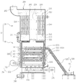
- the primary combustion unit includes a plurality of primary combustion chambers arranged in layers in a vertical direction for burning while continuously transporting the supplied waste plastic solid fuel, and the first one of the plurality of primary combustion chambers. Fuel and combustion gas transferred from the primary combustion chamber to one end of the upper primary combustion chamber are sequentially passed through the lower portion of the upper primary combustion chamber to the lower primary combustion chamber disposed under the upper primary combustion chamber.
- the primary air supply unit may include a plurality of primary air supply pipes for supplying air required for combustion to each of the plurality of primary combustion chambers.
- the combustion gas generated in the primary combustion unit 130 is circulated forcibly by the combustion gas induction unit 150 to be reburned in the secondary combustion unit 160, thereby enabling complete combustion.
- the combustion gas induction unit 150 By supplying heat generated by the recombustion of the combustion gas in the secondary combustion unit 160 to the primary combustion unit 130 to maintain the continuous combustion of the waste plastic solid fuel supplied to the waste plastic solid fuel
- the use of auxiliary fuel for incineration is eliminated, and waste heat and complete combustion gas discharged through the gas outlet 111 provided at the upper portion of the incinerator housing 110 may be supplied to the heat exchange unit 20 for utilization. By doing so, efficient energy operation is possible.
- control unit 190 controls the amount of waste plastic solid fuel transferred by the RPF injection screw conveyor 122 and uniformly burns the fuel in the primary air supply unit 140. And smooth operation of the toxic substances, such as dioxin, to completely control the operation of the RPF input screw conveyor 122 and the dust recovery screw conveyor 136 and to control the generation of harmful substances.
- the combustion gas generated in the primary combustion unit 130 by the combustion gas induction unit 150 is operated by the blower fan 152 to forcibly circulated and reburned to the secondary combustion unit 160, To control the air supply flow rate to the primary air supply unit 140 and the secondary air supply unit 170 and the air supply ratio between the primary air supply unit 140 and the secondary air supply unit 170. .
- the heat exchange part housing 210 is provided with a water supply inlet tube 211 at one side of the lower end so that the liquid heat medium is introduced into the inside, the liquid heat medium introduced from the water supply inlet tube 211 is Water discharge pipe 212 is provided on one side of the upper end to be discharged.
- the water supply inlet pipe 211 is installed at one side of the lower end such that the liquid heat medium flows into one side of the heat exchange part housing 210, and the water supply discharge pipe 212 is at one side of the upper end of the heat exchange part housing 210. It is installed, and the heat exchange between the liquid heat medium introduced from the water supply inlet pipe 211 and the combustion gas flowing out of the plurality of heat exchange tubes 250 inside the heat exchange part housing 210.
- a pump not shown
- the heated liquid heat medium may be supplied with hot water through the water supply pipe 212.
Abstract
Description
Claims (7)
- 상부에 연소가스가 배출되는 가스 배출구가 구비된 소각로 하우징;An incinerator housing having a gas outlet through which combustion gas is discharged;폐 플라스틱 고형연료를 이송하여 공급하는 연료공급부;A fuel supply unit which transfers and supplies waste plastic solid fuel;공급된 상기 폐 플라스틱 고형연료를 연속적으로 이송하면서 연소시키는 1차 연소부;A primary combustion unit configured to burn while continuously feeding the supplied waste plastic solid fuel;연소에 필요한 공기를 상기 1차 연소부에 공급하는 1차 공기 공급부;A primary air supply unit supplying air required for combustion to the primary combustion unit;상기 1차 연소부에서 발생된 연소가스를 상기 1차 연소실의 하부 방향으로 유도하는 연소가스 유도부;Combustion gas induction unit for inducing the combustion gas generated in the primary combustion unit in the lower direction of the primary combustion chamber;상기 1차 연소부의 하부에 배치되고, 상기 연소가스 유도부를 통하여 공급된 연소가스를 재연소시키기 위하여 상부에서 하부로 분사하는 하향식 분사 노즐부를 구비하는 2차 연소부; 및A secondary combustion unit disposed below the primary combustion unit and having a downward injection nozzle unit injecting from the upper side to the lower side to reburn the combustion gas supplied through the combustion gas induction unit; And상기 2차 연소부의 하부에 배치되고, 연소에 필요한 공기를 하부에서 상부로 분사함으로써 상기 2차 연소부에 공급하는 2차 공기 공급부;를 포함하는, 폐 플라스틱 고형연료 소각로.And a secondary air supply unit disposed below the secondary combustion unit and supplied to the secondary combustion unit by injecting air necessary for combustion from the lower side to the upper side.
- 상부에 연소가스가 배출되는 가스 배출구가 구비된 소각로 하우징; 폐 플라스틱 고형연료를 이송하여 공급하는 연료공급부; 공급된 상기 폐 플라스틱 고형연료를 연속적으로 이송하면서 연소시키는 1차 연소부; 연소에 필요한 공기를 상기 1차 연소부에 공급하는 1차 공기 공급부; 상기 1차 연소부에서 발생된 연소가스를 상기 1차 연소실의 하부 방향으로 유도하는 연소가스 유도부; 상기 1차 연소부의 하부에 배치되고, 상기 연소가스 유도부를 통하여 공급된 연소가스를 재연소시키기 위하여 상부에서 하부로 분사하는 하향식 분사 노즐부를 구비하는 2차 연소부; 및 상기 2차 연소부의 하부에 배치되고, 연소에 필요한 공기를 하부에서 상부로 분사함으로써 상기 2차 연소부에 공급하는 2차 공기 공급부;를 포함하는 소각부와,An incinerator housing having a gas outlet through which combustion gas is discharged; A fuel supply unit which transfers and supplies waste plastic solid fuel; A primary combustion unit configured to burn while continuously feeding the supplied waste plastic solid fuel; A primary air supply unit supplying air required for combustion to the primary combustion unit; Combustion gas induction unit for inducing the combustion gas generated in the primary combustion unit in the lower direction of the primary combustion chamber; A secondary combustion unit disposed below the primary combustion unit and having a downward injection nozzle unit injecting from the upper side to the lower side to reburn the combustion gas supplied through the combustion gas induction unit; And a secondary air supply unit disposed below the secondary combustion unit and supplied to the secondary combustion unit by injecting air required for combustion from the lower side to the upper side.하단부 일측의 급수 유입관 및 상단부 일측의 급수 배출관이 구비되고, 상부에서 내부 공간을 형성하는 상부 가스순환실 및 하부에서 내부 공간을 형성하는 하부 가스순환실이 형성되는 열교환부 하우징;상기 열교환부 하우징 내부에서 상기 중앙 가스통로의 주위를 둘러싸는 형태이고 상기 상부 가스순환실과 상기 하부 가스순환실을 연결하도록 연장되는 다수의 열교환관; 및, 상기 상부 가스순환실의 내부 공간을 좌우로 구획하는 경계벽과, 상단부 일측의 배기관이 구비되는 헤더;를 포함하는 열교환부를 포함하고,A heat exchanger housing having a water supply inlet tube at one side of the lower end and a water discharge pipe at one side of the upper end, wherein an upper gas circulation chamber forming an inner space at an upper portion thereof and a lower gas circulation chamber forming an inner space at a lower portion thereof are formed; A plurality of heat exchange tubes formed to enclose a periphery of the central gas passage and extend to connect the upper gas circulation chamber and the lower gas circulation chamber; And a heat exchange part including a boundary wall partitioning an inner space of the upper gas circulation chamber from side to side and a header having an exhaust pipe at one side of the upper end.상기 소각로 하우징의 측부 및 상부를 둘러싸며 하단부 일측으로부터 열매체가 유입되고 상단부 일측으로 열매체가 유출되어 상기 급수 유입관으로 열매체를 공급하는 열매체 재킷을 더 포함하는, 폐 플라스틱 고형연료 소각로.Waste plastic solid fuel incinerator surrounding the side and the upper portion of the incinerator housing and the heat medium is introduced from the lower end side and the heat medium flows out to the upper end side to supply the heat medium to the water supply inlet.
- 제1항 또는 제2항에 있어서,The method according to claim 1 or 2,상기 1차 연소부는, 공급된 상기 폐 플라스틱 고형연료를 연속적으로 이송하면서 연소시키는, 수직 방향으로 층을 이루어 배치된 복수의 1차 연소실을 포함하고,The primary combustion unit includes a plurality of primary combustion chambers arranged in layers in a vertical direction to combust while continuously feeding the supplied waste plastic solid fuel,상기 복수의 1차 연소실 중 상부의 1차 연소실에서 상기 상부의 1차 연소실 일 단부까지 이송된 연료 및 연소가스는, 상기 상부의 1차 연소실 일 단부의 하부를 통하여 상기 상부의 1차 연소실의 하부에 배치된 하부의 1차 연소실로 순차적으로 공급되며,The fuel and the combustion gas transferred from the upper primary combustion chamber to the one end of the upper primary combustion chamber among the plurality of primary combustion chambers are lowered through the lower portion of the upper primary combustion chamber through the lower portion of the upper primary combustion chamber. Sequentially supplied to the lower primary combustion chamber disposed in the상기 1차 공기 공급부는, 상기 복수의 1차 연소실 각각에 연소에 필요한 공기를 공급하는 복수의 1차 공기 공급관을 포함하는, 폐 플라스틱 고형연료 소각로.And said primary air supply unit comprises a plurality of primary air supply pipes for supplying air required for combustion to each of said plurality of primary combustion chambers.
- 제3항에 있어서,The method of claim 3,상기 연소가스 유도부는,The combustion gas induction unit,입구가 상기 복수의 1차 연소실 중 최하부의 1차 연소실의 일 단부에 연결되고 출구가 상기 하향식 분사 노즐부에 연결되도록 연장된 가스 회수관; 및A gas recovery pipe extending to an inlet connected to one end of a lowermost primary combustion chamber of the plurality of primary combustion chambers and to an outlet connected to the top-down injection nozzle; And상기 가스 회수관의 상기 입구와 상기 출구 사이에서 상기 1차 연소부에서 발생된 연소가스를 상기 하향식 분사 노즐부 방향으로 유도하는 송기팬;을 포함하는, 폐 플라스틱 고형연료 소각로.And an air blowing fan for guiding the combustion gas generated in the primary combustion unit in the direction of the downward injection nozzle between the inlet and the outlet of the gas recovery pipe.
- 제4항에 있어서,The method of claim 4, wherein상기 복수의 1차 연소실 각각은, 연료를 연속적으로 이송하기 위한 스크류 컨베이어; 및 상기 스크류 컨베이어의 축으로부터 상기 소각로 하우징의 측면을 관통하여 연장된 축의 적어도 일단에 설치되는 풀리;를 포함하고,Each of the plurality of primary combustion chambers includes a screw conveyor for continuously transporting fuel; And a pulley installed at at least one end of the shaft extending through the side surface of the incinerator housing from the shaft of the screw conveyor.상기 복수의 1차 연소실의 상기 풀리는 동력전달 벨트에 의해 서로 결속되어 상기 복수의 1차 연소실의 스크류 컨베이어 전체에 동력이 전달되는, 폐 플라스틱 고형연료 소각로.And said pulleys of said plurality of primary combustion chambers are coupled to each other by a power transmission belt such that power is transmitted to the entire screw conveyor of said plurality of primary combustion chambers.
- 제4항에 있어서,The method of claim 4, wherein상기 연료 공급부는,The fuel supply unit,상기 소각로 하우징의 외측에 설치된 RPF 투입 호퍼; 및An RPF input hopper installed outside the incinerator housing; And상기 RPF 투입 호퍼로 투입된 폐 플라스틱 고형연료를 상기 1차 연소부의 내부로 이송하기 위한 RPF 투입 스크류 컨베이어;를 포함하는, 폐 플라스틱 고형연료 소각로.And an RPF injection screw conveyor for transferring the waste plastic solid fuel injected into the RPF injection hopper into the primary combustion unit.
- 제4항에 있어서,The method of claim 4, wherein외부로부터 공기를 흡입하여 상기 1차 공기 공급부 및 상기 2차 공기 공급부로 송출하는 송풍기; 및A blower that sucks air from the outside and sends the air to the primary air supply unit and the secondary air supply unit; And상기 복수의 1차 연소실 중 최하부의 1차 연소실의 일 단부에서 배출되는 분진을 저장하기 위한 분진 저장탱크;를 더 포함하는, 폐 플라스틱 고형연료 소각로.And a dust storage tank for storing dust discharged from one end of the lowermost primary combustion chamber among the plurality of primary combustion chambers.
Priority Applications (4)
| Application Number | Priority Date | Filing Date | Title |
|---|---|---|---|
| US15/309,651 US10317075B2 (en) | 2014-05-14 | 2014-12-17 | Waste plastic solid fuel incinerator |
| EP14891888.1A EP3144592B1 (en) | 2014-05-14 | 2014-12-17 | Waste plastic solid fuel incinerator |
| CN201480078878.5A CN106662325B (en) | 2014-05-14 | 2014-12-17 | Waste plastic solid fuel incinerator |
| JP2017512614A JP6447718B2 (en) | 2014-05-14 | 2014-12-17 | Waste plastic solid fuel incinerator |
Applications Claiming Priority (2)
| Application Number | Priority Date | Filing Date | Title |
|---|---|---|---|
| KR10-2014-0057890 | 2014-05-14 | ||
| KR1020140057890A KR101513877B1 (en) | 2014-05-14 | 2014-05-14 | Refuse Plastic Fuel Incinerator |
Publications (1)
| Publication Number | Publication Date |
|---|---|
| WO2015174604A1 true WO2015174604A1 (en) | 2015-11-19 |
Family
ID=53053719
Family Applications (1)
| Application Number | Title | Priority Date | Filing Date |
|---|---|---|---|
| PCT/KR2014/012483 WO2015174604A1 (en) | 2014-05-14 | 2014-12-17 | Plastic waste solid fuel incinerator |
Country Status (6)
| Country | Link |
|---|---|
| US (1) | US10317075B2 (en) |
| EP (1) | EP3144592B1 (en) |
| JP (1) | JP6447718B2 (en) |
| KR (1) | KR101513877B1 (en) |
| CN (1) | CN106662325B (en) |
| WO (1) | WO2015174604A1 (en) |
Families Citing this family (10)
| Publication number | Priority date | Publication date | Assignee | Title |
|---|---|---|---|---|
| CN107490009A (en) * | 2017-09-28 | 2017-12-19 | 钦州学院 | Chemical spent material incinerator |
| CN107702127B (en) * | 2017-10-26 | 2019-05-03 | 绍兴三强机电科技有限公司 | Foam crushes burning and exhaust gas purification and treatment device |
| KR101971932B1 (en) * | 2017-11-14 | 2019-04-24 | 주식회사 신풍 | Environment-friendly multi-layer high-temperature incinerator |
| CN109556119A (en) * | 2018-12-28 | 2019-04-02 | 广东华祐新材料有限公司 | A kind of refuse incinerator |
| KR102126901B1 (en) * | 2019-08-21 | 2020-06-25 | 문영진 | System for controlling optimized combustion on separating boiler |
| CN110715304B (en) * | 2019-11-08 | 2020-08-04 | 浙江亿方新材料股份有限公司 | Industrial plastic scrapping treatment device |
| CN111594842B (en) * | 2020-05-27 | 2022-08-19 | 嘉兴学院 | Tower structure for burning paste waste |
| CN111594843B (en) * | 2020-05-27 | 2022-08-19 | 嘉兴学院 | Tower type incineration system for paste waste |
| KR102242849B1 (en) * | 2020-08-14 | 2021-04-22 | 유해권 | System for recycling waste heat using solid refuse fuel incinerator |
| TWI752851B (en) * | 2021-03-23 | 2022-01-11 | 吳克強 | Incinerator cooling device for reducing dioxin content and application method thereof |
Citations (4)
| Publication number | Priority date | Publication date | Assignee | Title |
|---|---|---|---|---|
| KR200226144Y1 (en) * | 2000-12-12 | 2001-06-01 | 정주산업개발주식회사 | Device for drying and incinerating the sludge of incinerating furnace |
| KR20110021283A (en) * | 2009-08-26 | 2011-03-04 | 위계대 | Boiler |
| KR20120110938A (en) * | 2011-03-30 | 2012-10-10 | 에스지티(주) | Boiler system |
| KR101311849B1 (en) * | 2013-06-27 | 2013-09-25 | 권명열 | Eco-friendly carbonization apparatus for treating organic waste |
Family Cites Families (29)
| Publication number | Priority date | Publication date | Assignee | Title |
|---|---|---|---|---|
| FR1025502A (en) * | 1949-11-30 | 1953-04-16 | Oerlikon Maschf | Solid fuel burner |
| US3602161A (en) * | 1967-12-19 | 1971-08-31 | Midland Ross Corp | Smokeless trash incinerator |
| US3543700A (en) * | 1969-07-07 | 1970-12-01 | Environmental Control Products | Air purifying incinerator apparatus |
| US4167909A (en) * | 1976-12-09 | 1979-09-18 | Dauvergne Hector A | Solid fuel burner |
| US4321878A (en) * | 1980-07-07 | 1982-03-30 | Segrest William W | Secondary hearth crematory |
| US4412889A (en) * | 1982-03-22 | 1983-11-01 | Kleenair Products Co., Inc. | Pyrolysis reaction apparatus |
| US4515089A (en) * | 1984-02-23 | 1985-05-07 | Sunburst Laboratories, Inc. | Incinerator having kinetic venturi isothermic grid burner system |
| CA1227969A (en) * | 1984-05-18 | 1987-10-13 | David R. Brookes | Incinerator and cremator |
| US4542703A (en) * | 1984-10-19 | 1985-09-24 | Msp, Inc. | Counter current incineration unit |
| SE461351B (en) * | 1988-04-05 | 1990-02-05 | Mitab Products Ab | incinerator |
| GB8826909D0 (en) * | 1988-11-17 | 1988-12-21 | Booth G | Combustion apparatus |
| AT400180B (en) * | 1990-01-10 | 1995-10-25 | Froeling Heizkessel Und Behael | SOLID FUEL HEATED UNDERBURNING BOILER |
| JPH0525131U (en) * | 1991-09-06 | 1993-04-02 | 株式会社高林工業所 | Incinerator |
| US5411714A (en) * | 1992-04-06 | 1995-05-02 | Wu; Arthur C. | Thermal conversion pyrolysis reactor system |
| JP3468925B2 (en) * | 1995-08-02 | 2003-11-25 | 三菱重工業株式会社 | Waste incineration equipment |
| CN2237782Y (en) * | 1995-11-02 | 1996-10-16 | 杨景森 | Continuous multi-hearth suspensed burning incinerator |
| JPH108064A (en) * | 1996-06-20 | 1998-01-13 | Hiroshi Shimizu | Gasification apparatus for combustible waste material |
| JP3676033B2 (en) * | 1997-05-23 | 2005-07-27 | 三菱重工業株式会社 | Waste incinerator |
| JP3055686B1 (en) * | 1999-03-15 | 2000-06-26 | 川崎重工業株式会社 | Method and apparatus for producing activated carbide |
| US6305302B2 (en) * | 1999-09-14 | 2001-10-23 | Waste Tire Gas Technologies, Inc. | Waste tire gasification in a negative ambient pressure environment |
| US6619218B2 (en) * | 2000-12-05 | 2003-09-16 | San Iku Co., Ltd. | Method and apparatus for making a pollutant harmless |
| JP2002180061A (en) * | 2000-12-18 | 2002-06-26 | Tokyo Yogyo Co Ltd | Carbonization oven and carbonization oven unit |
| US6758150B2 (en) * | 2001-07-16 | 2004-07-06 | Energy Associates International, Llc | System and method for thermally reducing solid and liquid waste and for recovering waste heat |
| KR20010088721A (en) * | 2001-08-25 | 2001-09-28 | ** | The hot water supply apparatus using the perfect combustion of the waste and the method thereof |
| JP2003120910A (en) * | 2001-10-16 | 2003-04-23 | Meidensha Corp | Heat treating equipment and its treating facility |
| AU2003239935A1 (en) * | 2002-06-03 | 2003-12-19 | Global Environmental Technologies, Llc | Process for the pyrolysis of medical waste and other waste materials |
| US20080072807A1 (en) * | 2006-09-22 | 2008-03-27 | Brookes David R | Gasifier and Incinerator for Biomass Sludge Destruction |
| CN201391999Y (en) * | 2009-03-25 | 2010-01-27 | 范高峰 | Micro-emission environment-protective boiler |
| JP5762713B2 (en) * | 2010-10-04 | 2015-08-12 | 株式会社キンセイ産業 | Dry distillation gasification incineration processing equipment |
-
2014
- 2014-05-14 KR KR1020140057890A patent/KR101513877B1/en active IP Right Grant
- 2014-12-17 JP JP2017512614A patent/JP6447718B2/en not_active Expired - Fee Related
- 2014-12-17 EP EP14891888.1A patent/EP3144592B1/en not_active Not-in-force
- 2014-12-17 US US15/309,651 patent/US10317075B2/en not_active Expired - Fee Related
- 2014-12-17 CN CN201480078878.5A patent/CN106662325B/en not_active Expired - Fee Related
- 2014-12-17 WO PCT/KR2014/012483 patent/WO2015174604A1/en active Application Filing
Patent Citations (4)
| Publication number | Priority date | Publication date | Assignee | Title |
|---|---|---|---|---|
| KR200226144Y1 (en) * | 2000-12-12 | 2001-06-01 | 정주산업개발주식회사 | Device for drying and incinerating the sludge of incinerating furnace |
| KR20110021283A (en) * | 2009-08-26 | 2011-03-04 | 위계대 | Boiler |
| KR20120110938A (en) * | 2011-03-30 | 2012-10-10 | 에스지티(주) | Boiler system |
| KR101311849B1 (en) * | 2013-06-27 | 2013-09-25 | 권명열 | Eco-friendly carbonization apparatus for treating organic waste |
Also Published As
| Publication number | Publication date |
|---|---|
| US20170268773A1 (en) | 2017-09-21 |
| EP3144592A1 (en) | 2017-03-22 |
| CN106662325A (en) | 2017-05-10 |
| JP2017520748A (en) | 2017-07-27 |
| KR101513877B1 (en) | 2015-04-23 |
| EP3144592A4 (en) | 2017-12-13 |
| US10317075B2 (en) | 2019-06-11 |
| CN106662325B (en) | 2020-01-14 |
| JP6447718B2 (en) | 2019-01-09 |
| EP3144592B1 (en) | 2019-05-01 |
Similar Documents
| Publication | Publication Date | Title |
|---|---|---|
| WO2015174604A1 (en) | Plastic waste solid fuel incinerator | |
| WO2016021785A1 (en) | Multi-layer high-temperature pyrolysis incineration apparatus | |
| KR100907269B1 (en) | Continuous combustion apparatus with divided combustion space by the centrifugal force and the combustion method thereof | |
| WO2013094879A1 (en) | Apparatus for pyrolysis using molten metal | |
| KR20120110938A (en) | Boiler system | |
| CN206094112U (en) | Sludge incineration system | |
| KR100330814B1 (en) | Centrifugal Combusting Method using the Air-flow in a Furnace | |
| KR101237761B1 (en) | Centrifugal continuous combustion apparatus having function of division on fly ash | |
| WO2015186866A1 (en) | Dry distillation gas fluidized bed pyrolysis gasification combustion device using microwaves | |
| CN107477586A (en) | A kind of low temperature pyrolyzer autoreaction garbage disposal furnace | |
| KR20090083838A (en) | Combustion apparatus for solid fuel | |
| WO2013147543A1 (en) | Integrated combustion boiler apparatus for pyrolyzing and gasifying solid fuel products | |
| JP2008082588A (en) | Waste incineration boiler device | |
| CN202938307U (en) | Tunnel type vaporizing combusting garbage incinerator | |
| KR101079853B1 (en) | Incinerator | |
| KR101093408B1 (en) | A burner using refused solid material | |
| KR100871921B1 (en) | A burning apparatus | |
| JP2007292363A (en) | Vertical incinerator for incinerating industrial waste | |
| CN117249438B (en) | High-efficiency and low-pollution garbage incinerator | |
| WO2023080345A1 (en) | Sludge treatment apparatus and excreta treatment apparatus including same | |
| CN107842857A (en) | Gasification, and combustion waste incinerator | |
| KR20120076703A (en) | Combustion apparatus of boiler using refuse derived fuel or refused plastic fuel | |
| CN112628754B (en) | Waste gasification melting treatment system and waste gasification melting treatment method | |
| WO2018038563A2 (en) | Boiler apparatus for waste incineration | |
| JPH0735321A (en) | Treatment device for combustible waste |
Legal Events
| Date | Code | Title | Description |
|---|---|---|---|
| 121 | Ep: the epo has been informed by wipo that ep was designated in this application |
Ref document number: 14891888 Country of ref document: EP Kind code of ref document: A1 |
|
| ENP | Entry into the national phase |
Ref document number: 2017512614 Country of ref document: JP Kind code of ref document: A |
|
| NENP | Non-entry into the national phase |
Ref country code: DE |
|
| REEP | Request for entry into the european phase |
Ref document number: 2014891888 Country of ref document: EP |
|
| WWE | Wipo information: entry into national phase |
Ref document number: 2014891888 Country of ref document: EP Ref document number: 15309651 Country of ref document: US |