WO2015174236A1 - 集光太陽光の受熱装置、反応装置及び加熱装置 - Google Patents
集光太陽光の受熱装置、反応装置及び加熱装置 Download PDFInfo
- Publication number
- WO2015174236A1 WO2015174236A1 PCT/JP2015/062332 JP2015062332W WO2015174236A1 WO 2015174236 A1 WO2015174236 A1 WO 2015174236A1 JP 2015062332 W JP2015062332 W JP 2015062332W WO 2015174236 A1 WO2015174236 A1 WO 2015174236A1
- Authority
- WO
- WIPO (PCT)
- Prior art keywords
- heat receiving
- receiving device
- heat
- sunlight
- heater
- Prior art date
- Legal status (The legal status is an assumption and is not a legal conclusion. Google has not performed a legal analysis and makes no representation as to the accuracy of the status listed.)
- Ceased
Links
Images


Classifications
-
- C—CHEMISTRY; METALLURGY
- C10—PETROLEUM, GAS OR COKE INDUSTRIES; TECHNICAL GASES CONTAINING CARBON MONOXIDE; FUELS; LUBRICANTS; PEAT
- C10J—PRODUCTION OF PRODUCER GAS, WATER-GAS, SYNTHESIS GAS FROM SOLID CARBONACEOUS MATERIAL, OR MIXTURES CONTAINING THESE GASES; CARBURETTING AIR OR OTHER GASES
- C10J3/00—Production of combustible gases containing carbon monoxide from solid carbonaceous fuels
- C10J3/02—Fixed-bed gasification of lump fuel
- C10J3/20—Apparatus; Plants
-
- B—PERFORMING OPERATIONS; TRANSPORTING
- B01—PHYSICAL OR CHEMICAL PROCESSES OR APPARATUS IN GENERAL
- B01J—CHEMICAL OR PHYSICAL PROCESSES, e.g. CATALYSIS OR COLLOID CHEMISTRY; THEIR RELEVANT APPARATUS
- B01J8/00—Chemical or physical processes in general, conducted in the presence of fluids and solid particles; Apparatus for such processes
- B01J8/005—Separating solid material from the gas/liquid stream
- B01J8/0055—Separating solid material from the gas/liquid stream using cyclones
-
- B—PERFORMING OPERATIONS; TRANSPORTING
- B01—PHYSICAL OR CHEMICAL PROCESSES OR APPARATUS IN GENERAL
- B01J—CHEMICAL OR PHYSICAL PROCESSES, e.g. CATALYSIS OR COLLOID CHEMISTRY; THEIR RELEVANT APPARATUS
- B01J8/00—Chemical or physical processes in general, conducted in the presence of fluids and solid particles; Apparatus for such processes
- B01J8/005—Separating solid material from the gas/liquid stream
- B01J8/006—Separating solid material from the gas/liquid stream by filtration
-
- B—PERFORMING OPERATIONS; TRANSPORTING
- B01—PHYSICAL OR CHEMICAL PROCESSES OR APPARATUS IN GENERAL
- B01J—CHEMICAL OR PHYSICAL PROCESSES, e.g. CATALYSIS OR COLLOID CHEMISTRY; THEIR RELEVANT APPARATUS
- B01J8/00—Chemical or physical processes in general, conducted in the presence of fluids and solid particles; Apparatus for such processes
- B01J8/02—Chemical or physical processes in general, conducted in the presence of fluids and solid particles; Apparatus for such processes with stationary particles, e.g. in fixed beds
- B01J8/0242—Chemical or physical processes in general, conducted in the presence of fluids and solid particles; Apparatus for such processes with stationary particles, e.g. in fixed beds the fluid flow within the bed being predominantly vertical
- B01J8/0257—Chemical or physical processes in general, conducted in the presence of fluids and solid particles; Apparatus for such processes with stationary particles, e.g. in fixed beds the fluid flow within the bed being predominantly vertical in a cylindrical annular shaped bed
-
- B—PERFORMING OPERATIONS; TRANSPORTING
- B01—PHYSICAL OR CHEMICAL PROCESSES OR APPARATUS IN GENERAL
- B01J—CHEMICAL OR PHYSICAL PROCESSES, e.g. CATALYSIS OR COLLOID CHEMISTRY; THEIR RELEVANT APPARATUS
- B01J8/00—Chemical or physical processes in general, conducted in the presence of fluids and solid particles; Apparatus for such processes
- B01J8/02—Chemical or physical processes in general, conducted in the presence of fluids and solid particles; Apparatus for such processes with stationary particles, e.g. in fixed beds
- B01J8/0285—Heating or cooling the reactor
-
- B—PERFORMING OPERATIONS; TRANSPORTING
- B01—PHYSICAL OR CHEMICAL PROCESSES OR APPARATUS IN GENERAL
- B01J—CHEMICAL OR PHYSICAL PROCESSES, e.g. CATALYSIS OR COLLOID CHEMISTRY; THEIR RELEVANT APPARATUS
- B01J8/00—Chemical or physical processes in general, conducted in the presence of fluids and solid particles; Apparatus for such processes
- B01J8/18—Chemical or physical processes in general, conducted in the presence of fluids and solid particles; Apparatus for such processes with fluidised particles
- B01J8/1836—Heating and cooling the reactor
-
- B—PERFORMING OPERATIONS; TRANSPORTING
- B01—PHYSICAL OR CHEMICAL PROCESSES OR APPARATUS IN GENERAL
- B01J—CHEMICAL OR PHYSICAL PROCESSES, e.g. CATALYSIS OR COLLOID CHEMISTRY; THEIR RELEVANT APPARATUS
- B01J8/00—Chemical or physical processes in general, conducted in the presence of fluids and solid particles; Apparatus for such processes
- B01J8/18—Chemical or physical processes in general, conducted in the presence of fluids and solid particles; Apparatus for such processes with fluidised particles
- B01J8/24—Chemical or physical processes in general, conducted in the presence of fluids and solid particles; Apparatus for such processes with fluidised particles according to "fluidised-bed" technique
- B01J8/38—Chemical or physical processes in general, conducted in the presence of fluids and solid particles; Apparatus for such processes with fluidised particles according to "fluidised-bed" technique with fluidised bed containing a rotatable device or being subject to rotation or to a circulatory movement, i.e. leaving a vessel and subsequently re-entering it
- B01J8/384—Chemical or physical processes in general, conducted in the presence of fluids and solid particles; Apparatus for such processes with fluidised particles according to "fluidised-bed" technique with fluidised bed containing a rotatable device or being subject to rotation or to a circulatory movement, i.e. leaving a vessel and subsequently re-entering it being subject to a circulatory movement only
- B01J8/388—Chemical or physical processes in general, conducted in the presence of fluids and solid particles; Apparatus for such processes with fluidised particles according to "fluidised-bed" technique with fluidised bed containing a rotatable device or being subject to rotation or to a circulatory movement, i.e. leaving a vessel and subsequently re-entering it being subject to a circulatory movement only externally, i.e. the particles leaving the vessel and subsequently re-entering it
-
- C—CHEMISTRY; METALLURGY
- C10—PETROLEUM, GAS OR COKE INDUSTRIES; TECHNICAL GASES CONTAINING CARBON MONOXIDE; FUELS; LUBRICANTS; PEAT
- C10B—DESTRUCTIVE DISTILLATION OF CARBONACEOUS MATERIALS FOR PRODUCTION OF GAS, COKE, TAR, OR SIMILAR MATERIALS
- C10B23/00—Other methods of heating coke ovens
-
- F—MECHANICAL ENGINEERING; LIGHTING; HEATING; WEAPONS; BLASTING
- F03—MACHINES OR ENGINES FOR LIQUIDS; WIND, SPRING, OR WEIGHT MOTORS; PRODUCING MECHANICAL POWER OR A REACTIVE PROPULSIVE THRUST, NOT OTHERWISE PROVIDED FOR
- F03G—SPRING, WEIGHT, INERTIA OR LIKE MOTORS; MECHANICAL-POWER PRODUCING DEVICES OR MECHANISMS, NOT OTHERWISE PROVIDED FOR OR USING ENERGY SOURCES NOT OTHERWISE PROVIDED FOR
- F03G6/00—Devices for producing mechanical power from solar energy
- F03G6/06—Devices for producing mechanical power from solar energy with solar energy concentrating means
- F03G6/062—Parabolic point or dish concentrators
-
- F—MECHANICAL ENGINEERING; LIGHTING; HEATING; WEAPONS; BLASTING
- F03—MACHINES OR ENGINES FOR LIQUIDS; WIND, SPRING, OR WEIGHT MOTORS; PRODUCING MECHANICAL POWER OR A REACTIVE PROPULSIVE THRUST, NOT OTHERWISE PROVIDED FOR
- F03G—SPRING, WEIGHT, INERTIA OR LIKE MOTORS; MECHANICAL-POWER PRODUCING DEVICES OR MECHANISMS, NOT OTHERWISE PROVIDED FOR OR USING ENERGY SOURCES NOT OTHERWISE PROVIDED FOR
- F03G6/00—Devices for producing mechanical power from solar energy
- F03G6/06—Devices for producing mechanical power from solar energy with solar energy concentrating means
- F03G6/063—Tower concentrators
-
- F—MECHANICAL ENGINEERING; LIGHTING; HEATING; WEAPONS; BLASTING
- F03—MACHINES OR ENGINES FOR LIQUIDS; WIND, SPRING, OR WEIGHT MOTORS; PRODUCING MECHANICAL POWER OR A REACTIVE PROPULSIVE THRUST, NOT OTHERWISE PROVIDED FOR
- F03G—SPRING, WEIGHT, INERTIA OR LIKE MOTORS; MECHANICAL-POWER PRODUCING DEVICES OR MECHANISMS, NOT OTHERWISE PROVIDED FOR OR USING ENERGY SOURCES NOT OTHERWISE PROVIDED FOR
- F03G6/00—Devices for producing mechanical power from solar energy
- F03G6/06—Devices for producing mechanical power from solar energy with solar energy concentrating means
- F03G6/065—Devices for producing mechanical power from solar energy with solar energy concentrating means having a Rankine cycle
- F03G6/067—Binary cycle plants where the fluid from the solar collector heats the working fluid via a heat exchanger
-
- F—MECHANICAL ENGINEERING; LIGHTING; HEATING; WEAPONS; BLASTING
- F03—MACHINES OR ENGINES FOR LIQUIDS; WIND, SPRING, OR WEIGHT MOTORS; PRODUCING MECHANICAL POWER OR A REACTIVE PROPULSIVE THRUST, NOT OTHERWISE PROVIDED FOR
- F03G—SPRING, WEIGHT, INERTIA OR LIKE MOTORS; MECHANICAL-POWER PRODUCING DEVICES OR MECHANISMS, NOT OTHERWISE PROVIDED FOR OR USING ENERGY SOURCES NOT OTHERWISE PROVIDED FOR
- F03G6/00—Devices for producing mechanical power from solar energy
- F03G6/071—Devices for producing mechanical power from solar energy with energy storage devices
-
- F—MECHANICAL ENGINEERING; LIGHTING; HEATING; WEAPONS; BLASTING
- F24—HEATING; RANGES; VENTILATING
- F24S—SOLAR HEAT COLLECTORS; SOLAR HEAT SYSTEMS
- F24S20/00—Solar heat collectors specially adapted for particular uses or environments
- F24S20/20—Solar heat collectors for receiving concentrated solar energy, e.g. receivers for solar power plants
-
- F—MECHANICAL ENGINEERING; LIGHTING; HEATING; WEAPONS; BLASTING
- F24—HEATING; RANGES; VENTILATING
- F24S—SOLAR HEAT COLLECTORS; SOLAR HEAT SYSTEMS
- F24S23/00—Arrangements for concentrating solar-rays for solar heat collectors
- F24S23/70—Arrangements for concentrating solar-rays for solar heat collectors with reflectors
- F24S23/75—Arrangements for concentrating solar-rays for solar heat collectors with reflectors with conical reflective surfaces
-
- F—MECHANICAL ENGINEERING; LIGHTING; HEATING; WEAPONS; BLASTING
- F24—HEATING; RANGES; VENTILATING
- F24S—SOLAR HEAT COLLECTORS; SOLAR HEAT SYSTEMS
- F24S60/00—Arrangements for storing heat collected by solar heat collectors
- F24S60/20—Arrangements for storing heat collected by solar heat collectors using chemical reactions, e.g. thermochemical reactions or isomerisation reactions
-
- F—MECHANICAL ENGINEERING; LIGHTING; HEATING; WEAPONS; BLASTING
- F28—HEAT EXCHANGE IN GENERAL
- F28D—HEAT-EXCHANGE APPARATUS, NOT PROVIDED FOR IN ANOTHER SUBCLASS, IN WHICH THE HEAT-EXCHANGE MEDIA DO NOT COME INTO DIRECT CONTACT
- F28D20/00—Heat storage plants or apparatus in general; Regenerative heat-exchange apparatus not covered by groups F28D17/00 or F28D19/00
- F28D20/0056—Heat storage plants or apparatus in general; Regenerative heat-exchange apparatus not covered by groups F28D17/00 or F28D19/00 using solid heat storage material
-
- B—PERFORMING OPERATIONS; TRANSPORTING
- B01—PHYSICAL OR CHEMICAL PROCESSES OR APPARATUS IN GENERAL
- B01J—CHEMICAL OR PHYSICAL PROCESSES, e.g. CATALYSIS OR COLLOID CHEMISTRY; THEIR RELEVANT APPARATUS
- B01J2208/00—Processes carried out in the presence of solid particles; Reactors therefor
- B01J2208/00008—Controlling the process
- B01J2208/00017—Controlling the temperature
- B01J2208/00433—Controlling the temperature using electromagnetic heating
- B01J2208/00451—Sunlight; Visible light
-
- B—PERFORMING OPERATIONS; TRANSPORTING
- B01—PHYSICAL OR CHEMICAL PROCESSES OR APPARATUS IN GENERAL
- B01J—CHEMICAL OR PHYSICAL PROCESSES, e.g. CATALYSIS OR COLLOID CHEMISTRY; THEIR RELEVANT APPARATUS
- B01J2219/00—Chemical, physical or physico-chemical processes in general; Their relevant apparatus
- B01J2219/00049—Controlling or regulating processes
- B01J2219/00245—Avoiding undesirable reactions or side-effects
- B01J2219/00247—Fouling of the reactor or the process equipment
-
- C—CHEMISTRY; METALLURGY
- C10—PETROLEUM, GAS OR COKE INDUSTRIES; TECHNICAL GASES CONTAINING CARBON MONOXIDE; FUELS; LUBRICANTS; PEAT
- C10J—PRODUCTION OF PRODUCER GAS, WATER-GAS, SYNTHESIS GAS FROM SOLID CARBONACEOUS MATERIAL, OR MIXTURES CONTAINING THESE GASES; CARBURETTING AIR OR OTHER GASES
- C10J2300/00—Details of gasification processes
- C10J2300/09—Details of the feed, e.g. feeding of spent catalyst, inert gas or halogens
- C10J2300/0913—Carbonaceous raw material
- C10J2300/0916—Biomass
-
- C—CHEMISTRY; METALLURGY
- C10—PETROLEUM, GAS OR COKE INDUSTRIES; TECHNICAL GASES CONTAINING CARBON MONOXIDE; FUELS; LUBRICANTS; PEAT
- C10J—PRODUCTION OF PRODUCER GAS, WATER-GAS, SYNTHESIS GAS FROM SOLID CARBONACEOUS MATERIAL, OR MIXTURES CONTAINING THESE GASES; CARBURETTING AIR OR OTHER GASES
- C10J2300/00—Details of gasification processes
- C10J2300/09—Details of the feed, e.g. feeding of spent catalyst, inert gas or halogens
- C10J2300/0913—Carbonaceous raw material
- C10J2300/093—Coal
-
- C—CHEMISTRY; METALLURGY
- C10—PETROLEUM, GAS OR COKE INDUSTRIES; TECHNICAL GASES CONTAINING CARBON MONOXIDE; FUELS; LUBRICANTS; PEAT
- C10J—PRODUCTION OF PRODUCER GAS, WATER-GAS, SYNTHESIS GAS FROM SOLID CARBONACEOUS MATERIAL, OR MIXTURES CONTAINING THESE GASES; CARBURETTING AIR OR OTHER GASES
- C10J2300/00—Details of gasification processes
- C10J2300/12—Heating the gasifier
- C10J2300/1284—Heating the gasifier by renewable energy, e.g. solar energy, photovoltaic cells, wind
-
- F—MECHANICAL ENGINEERING; LIGHTING; HEATING; WEAPONS; BLASTING
- F24—HEATING; RANGES; VENTILATING
- F24S—SOLAR HEAT COLLECTORS; SOLAR HEAT SYSTEMS
- F24S10/00—Solar heat collectors using working fluids
- F24S10/70—Solar heat collectors using working fluids the working fluids being conveyed through tubular absorbing conduits
- F24S10/75—Solar heat collectors using working fluids the working fluids being conveyed through tubular absorbing conduits with enlarged surfaces, e.g. with protrusions or corrugations
- F24S2010/751—Special fins
-
- F—MECHANICAL ENGINEERING; LIGHTING; HEATING; WEAPONS; BLASTING
- F24—HEATING; RANGES; VENTILATING
- F24S—SOLAR HEAT COLLECTORS; SOLAR HEAT SYSTEMS
- F24S23/00—Arrangements for concentrating solar-rays for solar heat collectors
- F24S23/70—Arrangements for concentrating solar-rays for solar heat collectors with reflectors
- F24S2023/88—Multi reflective traps
-
- F—MECHANICAL ENGINEERING; LIGHTING; HEATING; WEAPONS; BLASTING
- F24—HEATING; RANGES; VENTILATING
- F24S—SOLAR HEAT COLLECTORS; SOLAR HEAT SYSTEMS
- F24S80/00—Details, accessories or component parts of solar heat collectors not provided for in groups F24S10/00-F24S70/00
- F24S2080/03—Arrangements for heat transfer optimization
- F24S2080/05—Flow guiding means; Inserts inside conduits
-
- Y—GENERAL TAGGING OF NEW TECHNOLOGICAL DEVELOPMENTS; GENERAL TAGGING OF CROSS-SECTIONAL TECHNOLOGIES SPANNING OVER SEVERAL SECTIONS OF THE IPC; TECHNICAL SUBJECTS COVERED BY FORMER USPC CROSS-REFERENCE ART COLLECTIONS [XRACs] AND DIGESTS
- Y02—TECHNOLOGIES OR APPLICATIONS FOR MITIGATION OR ADAPTATION AGAINST CLIMATE CHANGE
- Y02E—REDUCTION OF GREENHOUSE GAS [GHG] EMISSIONS, RELATED TO ENERGY GENERATION, TRANSMISSION OR DISTRIBUTION
- Y02E10/00—Energy generation through renewable energy sources
- Y02E10/40—Solar thermal energy, e.g. solar towers
- Y02E10/46—Conversion of thermal power into mechanical power, e.g. Rankine, Stirling or solar thermal engines
-
- Y—GENERAL TAGGING OF NEW TECHNOLOGICAL DEVELOPMENTS; GENERAL TAGGING OF CROSS-SECTIONAL TECHNOLOGIES SPANNING OVER SEVERAL SECTIONS OF THE IPC; TECHNICAL SUBJECTS COVERED BY FORMER USPC CROSS-REFERENCE ART COLLECTIONS [XRACs] AND DIGESTS
- Y02—TECHNOLOGIES OR APPLICATIONS FOR MITIGATION OR ADAPTATION AGAINST CLIMATE CHANGE
- Y02E—REDUCTION OF GREENHOUSE GAS [GHG] EMISSIONS, RELATED TO ENERGY GENERATION, TRANSMISSION OR DISTRIBUTION
- Y02E60/00—Enabling technologies; Technologies with a potential or indirect contribution to GHG emissions mitigation
- Y02E60/14—Thermal energy storage
-
- Y—GENERAL TAGGING OF NEW TECHNOLOGICAL DEVELOPMENTS; GENERAL TAGGING OF CROSS-SECTIONAL TECHNOLOGIES SPANNING OVER SEVERAL SECTIONS OF THE IPC; TECHNICAL SUBJECTS COVERED BY FORMER USPC CROSS-REFERENCE ART COLLECTIONS [XRACs] AND DIGESTS
- Y02—TECHNOLOGIES OR APPLICATIONS FOR MITIGATION OR ADAPTATION AGAINST CLIMATE CHANGE
- Y02E—REDUCTION OF GREENHOUSE GAS [GHG] EMISSIONS, RELATED TO ENERGY GENERATION, TRANSMISSION OR DISTRIBUTION
- Y02E70/00—Other energy conversion or management systems reducing GHG emissions
- Y02E70/30—Systems combining energy storage with energy generation of non-fossil origin
-
- Y—GENERAL TAGGING OF NEW TECHNOLOGICAL DEVELOPMENTS; GENERAL TAGGING OF CROSS-SECTIONAL TECHNOLOGIES SPANNING OVER SEVERAL SECTIONS OF THE IPC; TECHNICAL SUBJECTS COVERED BY FORMER USPC CROSS-REFERENCE ART COLLECTIONS [XRACs] AND DIGESTS
- Y02—TECHNOLOGIES OR APPLICATIONS FOR MITIGATION OR ADAPTATION AGAINST CLIMATE CHANGE
- Y02P—CLIMATE CHANGE MITIGATION TECHNOLOGIES IN THE PRODUCTION OR PROCESSING OF GOODS
- Y02P20/00—Technologies relating to chemical industry
- Y02P20/10—Process efficiency
- Y02P20/133—Renewable energy sources, e.g. sunlight
Definitions
- the present invention relates to a heat receiving device, a reaction device, and a heating device for concentrated sunlight.
- pyrolysis and gasification are performed using concentrated sunlight (renewable energy) to produce hydrogen, carbon monoxide, methane, etc. Doing will create new energy.
- the produced mixed gas of hydrogen and carbon monoxide is used as a raw material for hydrocarbon fuels (kerosene, light oil, diesel oil, gasoline, DME (dimethyl ether), methanol, etc.), and methane is generally used as a clean fuel. ing.
- Patent Document 1 Technology development that decomposes water and produces hydrogen or the like by using high-temperature solar heat obtained by concentrating sunlight is being actively promoted. Since a transparent quartz plate is used at the entrance (window) of the concentrated sunlight, it cannot be applied to thermal decomposition reactions such as coal that generates tar and soot.
- Patent Document 2 technology development for use in the thermal decomposition of coke by concentrated sunlight (for example, Patent Document 2) is limited to conditions where tar and soot are not generated.
- Non-Patent Document 1 Recently, attempts have been made to heat air with concentrated sunlight and use it in a gas turbine (for example, Non-Patent Document 1). However, no heat dissipation measures are taken against the reflection or re-radiation of the concentrated sunlight incident on the heat receiving device, and the device installed around the heat receiving device is made of foam, and heat transfer and heat absorption are extremely It ’s bad.
- FIGS. 1-10 examples of conventional reactors are shown in FIGS.
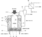
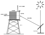
- FIG. 14 is a system for performing a hydrogen production reaction in a two-stage hydrothermal decomposition cycle using a metal oxide such as iron oxide filled in a reactor, in which the reactor shown in FIG. 14 is placed horizontally.
- the concentrated sunlight is guided to the reactor, and separately, coke and sand are introduced from the upper side wall of the reactor, water vapor is introduced from the bottom of the reactor, and hydrogen and the like are removed by a thermal decomposition reaction.
- This is a manufacturing system.
- This system is an example applied to the pyrolysis of coke, and is an operating condition where no soot or tar is generated.
- the heat receiving device is made of a heat-resistant material, and is made of inconel, alumina, silicon carbide or the like when the temperature is high, and is made of stainless steel or the like when the temperature is low. Part of the concentrated sunlight is emitted outside the heat receiving device by reflection or re-radiation.
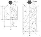
- the figure shows the case where the depth of the heat receiving device is about the same length as the diameter thereof, and the elevation angle ( ⁇ ) with respect to the center line of the heat receiving device is 10 degrees, 20 degrees, 30 with respect to the incident angle of the collected sunlight.
- the reflection state of light in the heat receiving device when assumed to be 40 degrees, 40 degrees, and 50 degrees is shown. It can be seen that the number of reflections in the heat receiving device is as small as 1 to 3, and that there is a large heat dissipation loss.
- FIG. 17B shows an example in which the depth of the heat receiving device is about twice as long as the diameter of the heat receiving device.
- the incident angle of the collected sunlight is the elevation angle ( ⁇ ) with respect to the center line of the heat receiving device. Shows a state of reflection in the heat receiving device when assumed to be 10 degrees, 20 degrees, 30 degrees, 40 degrees, and 50 degrees. It can be seen that the number of reflections is 2 to 6 and there are many heat dissipation losses.
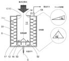
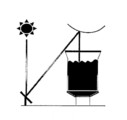
- FIG. 18 shows an example of a conventional heat storage system using sunlight collection.
- Thermal storage systems using sunlight collection include sensible heat storage (liquid: oil, solid: concrete, solid particles, etc.), latent heat storage (molten salt, etc.) and chemical heat storage. These heat storage systems are configured to be capable of steady operation both when the sun is shining and when it is not shining (when the sun is blocked by clouds and at night). The capacity of the heat storage system is determined by the operating time when the sun is not shining.
- This conventional example relates to a sensible heat storage system and a chemical heat storage system for solid particles. Since the chemical reaction material of chemical heat storage is in the form of particles, the sensible heat storage system and the chemical heat storage system for solid particles are similar.
- the inside of the heat receiving device is filled with a honeycomb structure (or foam).
- the condensed sunlight passes through the quartz plate (window) and enters the heat receiving device as shown in FIG. 18A, and the low-temperature air supplied to the heat receiving device is the honeycomb. It is heated through the structure and becomes high temperature.
- the hot air flows in parallel to the steam generator and the heat storage tank.
- the high-temperature air that has flowed to the steam generator heats water, generates steam, becomes low temperature, and is circulated to the heat receiving device.
- the generated steam generates electricity by a steam turbine and a generator.
- the high-temperature air that has flowed into the heat storage tank flows through small gaps between the metal oxide particles accommodated in the heat storage layer, it becomes a laminar flow and the heat transfer coefficient becomes small.
- the high-temperature air slowly gives heat to the heat storage particles, becomes a low temperature, and is circulated to the heat receiving device.
- the metal oxide particles heated in the heat storage tank release oxygen by a chemical reaction and store the heat of chemical reaction. That is, the metal oxide particles store both sensible heat and heat of chemical reaction.
- the present invention relates to a heat receiving device, a reaction device, and a heating device that can efficiently perform thermal decomposition and chemical reaction of coal or the like (including biomass such as wood) using solar heat obtained by collecting sunlight.
- a heat receiving device a reaction device, and a heating device that can efficiently perform thermal decomposition and chemical reaction of coal or the like (including biomass such as wood) using solar heat obtained by collecting sunlight.
- the concentrated sunlight is guided to the heat receiving device, the guided sunlight is not released outside the device by reflection or re-radiation, and the temperature in the heat receiving device can be set uniformly or arbitrarily, Combined with a reactor or heating device installed on the outer periphery of the heat receiving device and capable of operating under high pressure and high temperature conditions, it is possible to operate the thermal decomposition and chemical reaction of coal, etc. under the optimal conditions.
- An object of the present invention is to provide a heat receiving device, a reaction device, and a heating device.
- the heat receiving device for condensed sunlight includes a side portion, a bottom portion connected to the lower end of the side portion, and a ceiling portion connected to the upper end of the side portion, and has an opening in the ceiling portion.
- the side portion, the bottom portion, and the ceiling portion form a cavity in which the opening portion is opened and an inner wall that absorbs sunlight, and the inner wall of the side portion or the bottom portion emits sunlight.
- the reflector which reflects toward is provided.
- the diameter of the cavity is D
- the length of the cavity is L
- L 2D or more.
- a conical reflector is provided at the center of the bottom, and the reflector is a cone having a diameter of d or more and an elevation angle from the center line of the cavity is 30 to 60 degrees. It is characterized by.
- a reflector disposed on a concentric circle is further provided at the bottom.
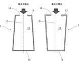
- the diameter of the ceiling and bottom of the cavity is different.
- the reaction device of the present invention is provided with any one of the above-described concentrated sunlight heat receiving devices, and around the heat receiving device so as to cover the side and bottom of the heat receiving device at a predetermined interval from the heat receiving device. It is characterized by comprising a reactor.
- a draft tube is provided inside the reactor.
- a heating device is provided with any one of the above-described concentrated sunlight heat receiving devices, and around the heat receiving device so as to cover a side portion and a bottom portion of the heat receiving device at a predetermined interval from the heat receiving device. It is characterized by comprising a heater.
- a fin is provided on the inner wall of the heater.
- a rectifier is provided at the bottom of the heater.
- the concentrated sunlight incident on the heat receiving device is confined in the heat receiving device, and the concentrated sunlight incident on the heat receiving device is effectively used. can do.
- FIG. 6 is a schematic diagram showing a reaction apparatus in Example 5.
- FIG. 10 is a schematic diagram showing a heating device in Example 6.
- FIG. 10 is a schematic diagram showing a heating device in Example 7.
- FIG. 10 is a schematic diagram showing a heating device in Example 8. It is a schematic diagram which shows the example which applied the heating apparatus in Example 9 to the solid particle thermal storage system. It is a schematic diagram which shows the example which applied the heating apparatus in Example 10 to the solid particle thermal storage system.
- 2 is a schematic diagram showing a reaction apparatus in Example 11. FIG.
- a heat receiving device made of silicon, stainless steel, or the like.
- the heat receiving device 1 is connected to the side portion 11 that forms a cylindrical side surface, the circular bottom portion 12 that is connected to the lower end of the side portion 11 to form the bottom surface of the heat receiving device 1, and the upper end of the side portion 11 to receive heat. It is comprised from the ceiling part 13 which forms the ceiling surface of the apparatus 1.
- FIG. A circular opening 14 is formed at the center of the ceiling 13.
- the heat receiving apparatus 1 has a cylindrical cavity 15 having an outer shape that is cylindrical, and an opening 14 is opened inside. Note that nothing is provided in the opening 14, and the cavity 15 communicates with the outside through the opening 14.
- a reactor 2 is provided around the heat receiving device 1 so as to cover most of the side portion 11 and the bottom portion 12 with a predetermined distance from the heat receiving device 1.
- a lead-out port 23 for leading out such gas is formed, and the reactor 2 is sealed except for the portions where the inlet ports 21 and 22 and the lead-out port 23 are formed.
- 31 is a heliostat
- 32 is a beam down type condensing mirror installed in a tower (not shown)
- the heliostat 31 and the beam down type condensing mirror 32 constitute a beam down type condensing system.
- the light from the sun S is condensed by this beam down type condensing system, and it guide
- only one heliostat 31 is shown in the figure, a large number of heliostats 31 are actually installed.
- coal particles are introduced into the reactor 2 from the inlet 22 and water vapor is introduced from the inlet 21.
- the condensed sunlight is guided from the opening 14 into the heat receiving apparatus 1 by the heliostat 31 and the beam-down condenser mirror 32.
- the heat receiving device 1 the condensed sunlight is repeatedly reflected on the inner wall of the side portion 11, the bottom portion 12, and the ceiling portion 13 of the heat receiving device 1, that is, the surface on the cavity 15 side, whereby the heat receiving device 1 is heated.
- the coal particles accommodated in the reactor 2 are heated by the heated heat receiving device 1.
- the pyrolysis reaction of coal proceeds, and the generated gas such as hydrogen and carbon monoxide is led out from the outlet 23.
- the heat receiving device 1 On the inner wall of the heat receiving device 1, it is necessary to reduce heat loss due to sunlight reflection and re-radiation and absorb the heat of sunlight at high speed. For this purpose, it is also effective to configure the heat receiving device 1 with a black material such as silicon carbide and apply black coating on the inner wall of the heat receiving device 1 if necessary.
- a black material such as silicon carbide
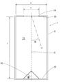
- FIG. D is the diameter of the cavity 15 of the heat receiving device 1
- L is the length of the cavity 15 of the heat receiving device 1
- d is the diameter d of the opening 14 that is the entrance of the condensed sunlight of the heat receiving device 1
- ⁇ is the heat receiving device 1.
- 16 is a conical reflector described later
- ⁇ is an elevation angle from the center line C of the cavity 15 of the reflector 16.
- the condensed sunlight is collected by a number of heliostats 31 and guided to the heat receiving device 1 at various incident angles.
- FIG. 3 shows a reflected path of the concentrated sunlight in the heat receiving device 1.
- the incident angle of the concentrated sunlight is expressed by an elevation angle ⁇ with respect to the center line C of the heat receiving device 1, and the elevation angle ⁇ is 10 degrees, 20 degrees, 30 degrees, 40 degrees, and 50 degrees, the concentrated sunlight receiving apparatus 1.
- the number of reflections on the inner wall is 5 or more. For this reason, the heat radiation loss is very small as compared with the prior art (see FIG. 17) in which the number of reflections is as few as 2 to 6 depending on the incident angle.
- the concentrated sunlight can be generated so that the collected sunlight incident on the heat receiving device 1 is not released to the outside due to reflection or re-radiation.
- part where the sunlight of the inner wall of the heat receiving apparatus 1 was irradiated absorbs most of the heat of sunlight, a part of the heat which could not be absorbed reaches another site
- the heat receiving device 1 for concentrated sunlight includes a side portion 11 that forms a substantially cylindrical side surface, and a substantially circular bottom portion that is connected to the lower end of the side portion 11 and forms a bottom surface. 12 and a ceiling portion 13 that is connected to the upper end of the side portion 11 to form a ceiling surface.
- a substantially circular opening 14 is formed at the center of the ceiling portion 13, and the opening 14 is opened.
- a substantially cylindrical cavity 15 is provided.
- the side portion 11, the bottom portion 12, and the ceiling portion 13 are formed with inner walls that absorb sunlight.
- the diameter of the cavity 15 is D
- the length of the cavity 15 is L
- the diameter of the opening 14 is d
- d D / 2 or less
- L 2D or more. Therefore, the condensed sunlight incident on the heat receiving device 1 can be confined in the heat receiving device 1, and the condensed sunlight incident on the heat receiving device 1 can be used effectively.
- a reflector that reflects sunlight toward the inner wall may be provided on the inner wall of the side portion 11 or the bottom portion 12. The reflector will be described in the following examples.
- a conical reflector 16 is installed at the center of the bottom 12 of the heat receiving device 1.
- the reflector 16 is preferably a cone having a diameter of d or more, and an elevation angle ⁇ from the center line C of the heat receiving device 1 is preferably 30 to 60 degrees.
- the conical reflector 16 is provided at the center of the bottom 12, and the reflector 16 is a cone having a diameter of d or more, and the elevation angle ⁇ from the center line C of the cavity 15. Is 30 degrees to 60 degrees, so that the collected sunlight incident at a small angle ⁇ from the center line C is prevented from being emitted to the outside of the heat receiving apparatus 1 with a small number of reflections, and the condensed light incident on the heat receiving apparatus 1 is prevented. Sunlight can be used effectively.
- two circular reflectors 17 having a triangular cross section are arranged concentrically on the bottom of the heat receiving device 1. Yes.
- sunlight can be uniformly reflected on the inner wall of the heat receiving device 1.
- the reflectors 16 and 17 have a convex outer surface, but a reflector having a concave outer surface may be provided on the bottom 12 of the heat receiving apparatus 1.
- a reflector having a concave outer surface may be provided on the bottom 12 of the heat receiving apparatus 1.
- the outer surface of the reflector is concave, the number of reflections until the sunlight is reflected toward the side surface increases, so that reflection with a convex outer surface is required to reflect toward the side surface with a small number of reflections.
- the body is preferred.
- a reflector having irregularities on the surface a reflector having an irregular surface, or a reflector having fine irregularities and a rough surface may be provided on the bottom 12 of the heat receiving device 1.
- a reflector may not be provided, and instead, sunlight may be irregularly reflected by forming fine irregularities on the inner wall surfaces of the side portion 11 and the bottom portion 12 of the heat receiving device 1.
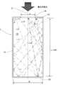
- FIG. 6 shows an example in which the diameters of the top and bottom of the heat receiving device 1 are changed.
- FIG. 7 shows an example in which a fluidized bed type reactor 4 is installed on the outer periphery of the heat receiving device 1.
- the condensed sunlight enters the heat receiving device 1 and is reflected by the conical reflector 16 installed on the bottom 12 or the circular reflector 17 having a circular cross section, and the inner wall of the heat receiving device 1 is uniformly heated.
- the heat receiving device 1 is made of inconel, alumina, silicon carbide, stainless steel or the like.
- the fluidized bed 41 is supplied with coal particles from the inlet 42, sand from the inlet 43, water vapor from the inlet 44 and, if necessary, fluidizing gas.
- the fluidized bed 41 rapidly absorbs heat from the outer wall of the heat receiving device 1 by a stirring action by the flow of gas and sand.
- Coal and water vapor are heated and decomposed and reacted with hydrogen, carbon monoxide, methane gas, etc., and discharged from the top of the fluidized bed 41. Since these gases are accompanied by undecomposed coal, ash, sand, etc., the coarse coal particles and sand are separated by the cyclone separator 45, and the separated coarse coal particles and sand are supplied to the fluidized bed 41 again. . Fine particles that could not be separated by the cyclone separator 45 are removed by the filter separator 46 and collected separately.
- the reaction apparatus can be composed entirely of metal, it can be applied to chemical reaction conditions of high temperature and high pressure.
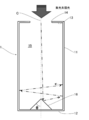
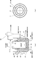
- FIG. 8 shows an example in which the heater 5 is installed on the outer periphery of the heat receiving device 1.
- the condensed sunlight enters the heat receiving device 1 and is reflected by the conical reflector 16 installed on the bottom 12 and the circular reflector 17 having a circular cross section, and the inner wall of the heat receiving device 1 is uniformly heated.
- the heat receiving device 1 is made of inconel, alumina, silicon carbide, stainless steel or the like.
- a large number of specially shaped fins 51 are attached to the inner wall of the heater 5, and the fins 51 rapidly take away the heat of the heat receiving device 1 and are used to raise the temperature of the air. Thus, the heat transfer area is increased by the fins 51, and the air in the heater 5 is effectively heated.
- the angle ⁇ 1 at the tip of the fin 51 is preferably 10 to 30 degrees, although it depends on the shape of the heater 5 and the operating conditions.
- a rectifier 52 is installed at the bottom of the heater 5, but this is for adjusting the gas flow and reducing the generation of vortices.
- the angle ⁇ 2 formed by the slope of the rectifier 52 and the center line C of the heat receiving device 1 is preferably 20 to 60 degrees, although it depends on the shape of the heater 5 and the operating conditions.
- the low temperature gas introduced from the inlet 53 provided at the bottom of the heater 5 is heated in the heater 5 and discharged as a high temperature gas from the outlet 54 provided at the top of the heater 5.
- the obtained high-temperature gas is used for power generation by a high-temperature gas turbine (not shown), sensible heat storage, latent heat storage, chemical heat storage, etc. (not shown).
- FIG. 9 shows another example in which a fluidized bed type heater 6 is installed on the outer periphery of the heat receiving device 1.
- Low temperature gas is supplied to the fluidized bed 61 from the inlet 62, and the heat of the heat receiving device 1 is rapidly taken away by the gas in the fluidized bed 61.
- the fluidized bed 61 acts as a heat exchanger having a high heat transfer rate.
- the gas deprived of heat is discharged as a high-temperature gas from the outlet 63 provided at the top of the heater 6.
- Reference numeral 64 denotes an inlet for introducing the sand constituting the fluidized bed 61 into the heater 6.
- FIG. 10 shows an example in which Example 6 and Example 7 are combined.
- a large number of specially shaped fins 71 are attached to the inner wall of the heater 7, and the heat of the heat receiving device 1 is rapidly removed to be used for raising the temperature of the air.
- a rectifier 72 is installed at the bottom of the heater 5.
- the fin 71 functions to promote heat transfer by the action of stirring the fluidized bed 73 and the gas that flows through the fluidized bed 73. Further, the scale attached to the fins 71 is removed by the random movement of the particles in the fluidized bed 73.
- the low-temperature gas introduced from the inlet 74 provided at the bottom of the heater 7 is heated in the heater 7 and discharged as a high-temperature gas from the outlet 75 provided at the top of the heater 7.
- Reference numeral 76 denotes an inlet for introducing the sand constituting the fluidized bed 73 into the heater 7.
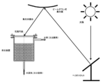
- Fig. 11 shows an example in which a fluidized bed heating device is applied to a solid particle heat storage system.
- the condensed sunlight enters the heat receiving device 1 as shown in FIG.
- a fluidized bed type heater 8 is installed on the outer periphery of the heat receiving device 1, and most of the heat of the concentrated sunlight received by the heat receiving device 1 is rapidly heated in the fluidized bed 81 accommodated in the heater 8. Communicated.
- low temperature air is supplied to the heater 8 from an inlet 82 provided at the bottom of the heater 8, and a fluidized bed 81 is supplied from an inlet 83 provided at a side of the heater 8.
- Metal oxide particles as heat storage particles to be configured are supplied.
- the fluidized bed 81 is vigorously fluidized by the air supplied from the inlet 82, so that the air and the metal oxide particles are rapidly heated to a high temperature.
- the heated metal oxide particles release oxygen by a chemical reaction and store heat. That is, the metal oxide particles store both sensible heat and reaction heat.
- metal oxide particles barium oxide (BaO 2 ), cobalt oxide (Co 3 O 4 ), manganese oxide (Mn 2 O 3 ), copper oxide (CuO), or the like can be used.
- the reaction formula when cobalt oxide is used is as follows. 3Co 3 O 4 ⁇ 3CoO + 0.5O 2 - 844kJ / (kg of Co 3 O 4) at about 1,200 ° C. (endothermic)
- the high temperature air is guided to the cyclone separator 84 from the top of the heater 8, and the fine particles contained in the air are removed by the cyclone separator 84 and stored in the storage tank 85.
- the air flows to the steam generator 86, water is heated by the steam generator 86 to generate steam, and the temperature is lowered and returned to the heater 8.
- the above air circulation is performed by the blower 87.
- the steam generated by the steam generator 86 rotates the steam turbine 88, and then returns to the steam generator 86 via the condenser 89 and the blower 90.
- the generator 91 generates electricity by the rotation of the steam turbine 88.
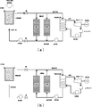
- the metal oxide particles are transferred from the heater 8 to the other heat storage tank 94, and at the same time, low-temperature metal oxide particles are supplied from the one heat storage tank 93 to the heater 8 by the discharging device 95. In this way, thereafter, the metal oxide particles are transferred to the heat storage tanks 93 and 94 alternately.
- the example of two heat storage tanks was shown here, it is also possible to install many heat storage tanks and increase the amount of heat storage.
- the valves are switched as shown in FIG. 11B to circulate air only between the heat storage tanks 93 and 94 and the steam generator 86. That is, the circulation of air between the heater 8 and the steam generator 86 is stopped. Also, the payout devices 95 and 96 are stopped.
- the air is supplied to the heat storage tanks 93, 94 from the bottom of the heat storage tanks 93, 94, passes between the metal oxide particles accommodated in the heat storage tanks 93, 94, and then the steam generator 86 from the top of the heat storage tanks 93, 94. Sent to. Inside the heat storage tanks 93 and 94, the metal oxide particles react with oxygen to generate heat, and the air is heated.
- the air heated in the heat storage tanks 93 and 94 flows to the steam generator 86, heats the water in the steam generator 86 to generate steam, becomes a low temperature, and returns to the heat storage tanks 93 and 94.
- the above air circulation is also performed by the blower 87.
- the steam generated by the steam generator 86 rotates the steam turbine 88, and then returns to the steam generator 86 via the condenser 89 and the blower 90.
- the generator 91 generates electricity by the rotation of the steam turbine 88.
- the present embodiment is a modification of the ninth embodiment, and uses metal oxide particles having a small particle diameter to transfer the metal oxide particles from the heater 8 to the heat storage tanks 93 and 94 by entraining the airflow. Yes.
- a fluidized bed type heater 8 is installed on the outer periphery of the heat receiving device 1, and most of the heat of the concentrated sunlight received by the heat receiving device 1 is rapidly heated in the fluidized bed 81 accommodated in the heater 8. Communicated. At this time, low temperature air is supplied to the heater 8 from an inlet 82 provided at the bottom of the heater 8, and a fluidized bed 81 is supplied from an inlet 83 provided at a side of the heater 8.
- Metal oxide particles as heat storage particles to be configured are supplied.
- the fluidized bed 81 is vigorously fluidized by the air supplied from the inlet 82, so that the air and the metal oxide particles are rapidly heated to a high temperature.
- the heated metal oxide particles release oxygen by a chemical reaction and store heat. That is, the metal oxide particles store both sensible heat and reaction heat.
- the mixture of high-temperature air and metal oxide particles is guided from the top of the heater 8 to one cyclone separator 97, and the high-temperature metal oxide particles are separated from the air by the cyclone separator 97 and sent to the heat storage tank 93. .
- low temperature metal oxide particles are supplied from the other heat storage tank 94 to the heater 8 by the discharge device 96.
- the air from which the metal oxide particles have been separated by the cyclone separators 97 and 98 flows to the steam generator 86, where water is heated by the steam generator 86 to generate steam, and the temperature is lowered and returned to the heater 8. It is.
- the above air circulation is performed by the blower 87.
- the steam generated by the steam generator 86 rotates the steam turbine 88, and then returns to the steam generator 86 via the condenser 89 and the blower 90.
- the generator 91 generates electricity by the rotation of the steam turbine 88.
- the valve When the sun is not shining, the valve is switched as shown in FIG. 12B to circulate air only between the heat storage tanks 93 and 94 and the steam generator 86. That is, the circulation of air between the heater 8 and the steam generator 86 is stopped. Also, the payout devices 95 and 96 are stopped.
- the air is supplied to the heat storage tanks 93, 94 from the bottom of the heat storage tanks 93, 94, passes between the metal oxide particles accommodated in the heat storage tanks 93, 94, and then the steam generator 86 from the top of the heat storage tanks 93, 94. Sent to. Inside the heat storage tanks 93 and 94, the metal oxide particles react with oxygen to generate heat, and the air is heated.
- the air heated in the heat storage tanks 93 and 94 flows to the steam generator 86, heats the water by the steam generator 86 to generate steam, and is returned to the heat storage tanks 93 and 94.
- the above air circulation is also performed by the blower 87.
- the steam generated by the steam generator 86 rotates the steam turbine 88, and then returns to the steam generator 86 via the condenser 89 and the blower 90.
- the generator 91 generates electricity by the rotation of the steam turbine 88.
- FIG. 13 shows a modification of the fifth embodiment.
- a draft pipe 47 is installed outside the side portion 11 of the heat receiving device 1 inside the reactor 4 to constitute an internal circulation type fluidized bed type reaction device.
- the draft tube 47 is formed of a cylinder having a diameter larger than that of the heat receiving device 1, and the introduction port 44 is disposed outside the side portion 11 of the heat receiving device 1 and inside the draft tube 47 when viewed from above. .
- the draft tube 47 is disposed so as to be buried in the fluidized bed 41.
- the water vapor and the flowing gas introduced from the introduction port 44 flow between the heat receiving device 1 and the draft pipe 47, and the fluidized bed 41 flows along with the flow of the water vapor and the flow gas introduced from the introduction port 44.
- a so-called internal circulation type flow is formed in which the fluidized bed 41 rises inside the draft pipe 47 and then falls outside the draft pipe 47 and rises again inside the draft pipe 47.
- the energy of the concentrated sunlight is absorbed by the inner wall of the heat receiving device 1, and the inner wall reaches the highest temperature. Therefore, in order to advance the reaction efficiently in the reactor 4, it is necessary to rapidly take heat into the reactor 4 from the inner wall.
- the particles in the fluidized bed 41 flow in a systematic manner, so that the heat conduction efficiency in the reactor 4 is extremely high. For this reason, the heat of the heat receiving device 1 is quickly taken into the reactor 4. Further, due to the flow, the temperature distribution of the fluidized bed 41 becomes substantially uniform. Therefore, the reaction can be efficiently advanced in the entire fluidized bed 41.
Landscapes
- Engineering & Computer Science (AREA)
- Chemical & Material Sciences (AREA)
- Combustion & Propulsion (AREA)
- Life Sciences & Earth Sciences (AREA)
- Sustainable Energy (AREA)
- Sustainable Development (AREA)
- Organic Chemistry (AREA)
- Mechanical Engineering (AREA)
- General Engineering & Computer Science (AREA)
- Chemical Kinetics & Catalysis (AREA)
- Physics & Mathematics (AREA)
- Thermal Sciences (AREA)
- Oil, Petroleum & Natural Gas (AREA)
- Fluid Mechanics (AREA)
- General Chemical & Material Sciences (AREA)
- Materials Engineering (AREA)
- Physical Or Chemical Processes And Apparatus (AREA)
Abstract
Description
3Co3O4 → 3CoO + 0.5O2 - 844kJ/(kg of Co3O4) at 約1,200℃(吸熱)
高温となった空気は、加熱器8の頂部からサイクロン分離機84へ導かれ、空気に含まれた微粉粒子は、サイクロン分離機84により除去され貯槽85に貯められる。その後、空気は、蒸気発生器86に流れ、蒸気発生器86で水を加熱して蒸気を発生させて低温になり、加熱器8に戻される。なお、以上の空気の循環は送風機87により行われる。蒸気発生器86で発生した蒸気は、蒸気タービン88を回し、その後、コンデンサー89、送風機90を経由して蒸気発生器86に戻される。発電機91は、蒸気タービン88の回転により電気を発生させる。
3CoO + 0.5O2 + 844kJ/(kg of Co3O4) → 3Co3O4 at 約900℃(放熱=発熱)
蓄熱槽93、94で加熱された空気は、蒸気発生器86に流れ、蒸気発生器86で水を加熱して蒸気を発生させて低温になり、蓄熱槽93、94に戻される。なお、以上の空気の循環も送風機87により行われる。蒸気発生器86で発生した蒸気は、蒸気タービン88を回し、その後、コンデンサー89、送風機90を経由して蒸気発生器86に戻される。発電機91は、蒸気タービン88の回転により電気を発生させる。
2,4 反応器
5,6,7,8 加熱器
11 側部
12 底部
13 天井部
14 開口部
15 空洞
16 反射体
17 反射体
47 ドラフト管
51,71 フィン
52,72 整流体
C 空洞15の中心線
D 空洞15の直径
d 開口部14の直径
L 空洞15の長さ
θ 空洞15の中心線Cからの仰角
α 集光太陽の入射角度で、空洞15の中心線Cからの仰角
Claims (13)
- 側部と、この側部の下端に接続する底部と、前記側部の上端に接続する天井部とを備え、前記天井部に開口部を有し、前記側部、前記底部、前記天井部によって、前記開口部が開口した空洞と、太陽光を吸収する内壁とが形成されるとともに、前記側部又は前記底部の内壁には太陽光を前記内壁に向けて反射する反射体が設けられたことを特徴とする集光太陽光の受熱装置。
- 前記空洞の内部における前記開口部を含む天井部の面積をS、前記開口部の面積をsとしたときに、s=S/4以下としたことを特徴とする請求項1記載の集光太陽光の受熱装置。
- 前記空洞は略円柱形、前記開口部は略円形であって、前記空洞の直径をD、前記空洞の長さをL、前記開口部の直径をdとしたときに、d=D/2以下、L=2D以上としたことを特徴とする請求項1記載の集光太陽光の受熱装置。
- 前記底部の中心部に円錐状の反射体が設けられるとともに、この反射体は、直径がd以上の円錐であって、前記空洞の中心線からの仰角が30度~60度であることを特徴とする請求項3記載の集光太陽光の受熱装置。
- 前記底部にさらに同心円上に配置された反射体が設けられたことを特徴とする請求項4記載の集光太陽光の受熱装置。
- 前記空洞の天井部と底部の直径を異ならせたことを特徴とする請求項3~5のいずれかに記載の集光太陽光の受熱装置。
- インコネル、アルミナ、炭化珪素、ステンレス鋼のいずれかから構成されたことを特徴とする請求項1~6のいずれかに記載の集光太陽光の受熱装置。
- 黒い材質から構成され、又は内壁に黒色の塗装が施されたことを特徴とする請求項7記載の集光太陽光の受熱装置。
- 請求項1~8のいずれかに記載の集光太陽光の受熱装置と、この受熱装置の周囲に前記受熱装置と所定の間隔をおいて前記受熱装置の側部と底部を覆うように設けられた反応器とからなることを特徴する反応装置。
- 前記反応器の内部にドラフト管を設けたことを特徴とする請求項9記載の反応装置。
- 請求項1~8のいずれかに記載の集光太陽光の受熱装置と、この受熱装置の周囲に前記受熱装置と所定の間隔をおいて前記受熱装置の側部と底部を覆うように設けられた加熱器とからなることを特徴する加熱装置。
- 前記加熱器の内壁にフィンを設けたことを特徴とする請求項11記載の加熱装置。
- 前記加熱器の底部に整流体を設けたことを特徴とする請求項12記載の加熱装置。
Priority Applications (3)
| Application Number | Priority Date | Filing Date | Title |
|---|---|---|---|
| US15/310,354 US10260014B2 (en) | 2014-05-13 | 2015-04-23 | Concentrated solar heat receiver, reactor, and heater |
| JP2016519188A JP6440267B2 (ja) | 2014-05-13 | 2015-04-23 | 集光太陽光の受熱装置、反応装置及び加熱装置 |
| AU2015260468A AU2015260468B2 (en) | 2014-05-13 | 2015-04-23 | Concentrated sunlight heat receiver, reactor, and heater |
Applications Claiming Priority (2)
| Application Number | Priority Date | Filing Date | Title |
|---|---|---|---|
| JP2014-099859 | 2014-05-13 | ||
| JP2014099859 | 2014-05-13 |
Publications (1)
| Publication Number | Publication Date |
|---|---|
| WO2015174236A1 true WO2015174236A1 (ja) | 2015-11-19 |
Family
ID=54479780
Family Applications (1)
| Application Number | Title | Priority Date | Filing Date |
|---|---|---|---|
| PCT/JP2015/062332 Ceased WO2015174236A1 (ja) | 2014-05-13 | 2015-04-23 | 集光太陽光の受熱装置、反応装置及び加熱装置 |
Country Status (4)
| Country | Link |
|---|---|
| US (1) | US10260014B2 (ja) |
| JP (1) | JP6440267B2 (ja) |
| AU (1) | AU2015260468B2 (ja) |
| WO (1) | WO2015174236A1 (ja) |
Cited By (8)
| Publication number | Priority date | Publication date | Assignee | Title |
|---|---|---|---|---|
| CN105623744A (zh) * | 2015-12-31 | 2016-06-01 | 西北大学 | 一种太阳能驱动的煤热解耦合半焦气化的反应器及方法 |
| CN107413284A (zh) * | 2017-05-08 | 2017-12-01 | 西安交通大学 | 一种太阳能颗粒催化式腔体吸热反应器及其使用方法 |
| ES2648148A1 (es) * | 2017-03-09 | 2017-12-28 | Universidad Carlos Iii De Madrid | Sistema óptico de haz descendente lineal solar |
| JP2019156705A (ja) * | 2018-03-16 | 2019-09-19 | 株式会社Ihi | 水素製造装置および水素製造方法 |
| EP3715744A1 (fr) | 2019-03-28 | 2020-09-30 | Four Solaire Developpement | Usine solaire et procédé de transformation |
| CN115304029A (zh) * | 2022-08-26 | 2022-11-08 | 西安交通大学 | 一种优化能量分配策略的被动热管理式太阳能高温反应器 |
| JP2023522531A (ja) * | 2020-02-03 | 2023-05-31 | マガルディ パワー ソシエタ ペル アチオニ | 多重反射に基づく太陽起源の熱エネルギーの貯蔵のための装置 |
| CN118836584A (zh) * | 2024-07-18 | 2024-10-25 | 北京理工大学 | 一种并联式太阳能光热化学耦合月面资源利用系统及方法 |
Families Citing this family (10)
| Publication number | Priority date | Publication date | Assignee | Title |
|---|---|---|---|---|
| PL3212925T3 (pl) * | 2014-10-31 | 2020-05-18 | Solar Wind Reliance Initiatives (Swri) Ltd. | Połączony system wytwarzania energii wiatrowej i słonecznej |
| ITUB20152907A1 (it) * | 2015-08-05 | 2017-02-05 | Magaldi Ind Srl | Dispositivo, impianto e metodo ad alto livello di efficienza energetica per l?impiego di energia termica di origine solare |
| TW201839259A (zh) * | 2017-02-01 | 2018-11-01 | 義大利商馬加帝電力公司 | 使用源自太陽之熱能之高能效率裝置、系統及方法 |
| WO2019204337A1 (en) * | 2018-04-16 | 2019-10-24 | National Technology & Engineering Solutions Of Sandia, Llc | Multi-stage falling particle receivers |
| US20220026163A1 (en) * | 2019-01-29 | 2022-01-27 | National University Corporation Tokai National Higher Education And Research System | Heat storage device |
| CN110864465B (zh) * | 2019-11-29 | 2025-03-14 | 广东技术师范大学 | 一种光聚热发电装置 |
| KR102361493B1 (ko) * | 2021-07-05 | 2022-02-09 | 한국교통대학교산학협력단 | 확대된 광노출 구조를 갖는 입자기반 태양열 흡수장치 |
| CN113578209A (zh) * | 2021-08-19 | 2021-11-02 | 西安交通大学 | 一种可昼夜连续运行的磁约束太阳能光热互补流化床反应器 |
| US12222137B2 (en) * | 2023-06-26 | 2025-02-11 | Sol Energia Inc. | Thermal energy storage systems and methods |
| CN119333976B (zh) * | 2024-11-05 | 2025-07-11 | 浙江大学 | 一种基于新型腔式吸收器的塔式太阳能聚光吸热系统 |
Citations (11)
| Publication number | Priority date | Publication date | Assignee | Title |
|---|---|---|---|---|
| US1661473A (en) * | 1924-06-10 | 1928-03-06 | Robert H Goddard | Accumulator for radiant energy |
| US4033118A (en) * | 1974-08-19 | 1977-07-05 | Powell William R | Mass flow solar energy receiver |
| JPS54108944A (en) * | 1978-02-15 | 1979-08-27 | Kaname Yamazoe | Heat receiving device of solar heat |
| JPS55144091A (en) * | 1979-04-13 | 1980-11-10 | Us Government | Generating of combustible gas from carbonaceous material |
| JP2008523351A (ja) * | 2004-12-15 | 2008-07-03 | シェク ラボズ−ソーラー ハイドロゲン エナジー コーポレイション | 太陽エネルギー収集装置および方法 |
| US20090205638A1 (en) * | 2008-02-19 | 2009-08-20 | Peter Corcoran | Solar Receiver for a Photo-Bioreactor |
| JP2009535599A (ja) * | 2006-04-30 | 2009-10-01 | 紀文 張 | 集光及び集熱を行う太陽エネルギー装置 |
| JP2011163593A (ja) * | 2010-02-05 | 2011-08-25 | Mitsubishi Heavy Ind Ltd | 太陽熱受熱器 |
| US20120186251A1 (en) * | 2009-09-10 | 2012-07-26 | Yeda Research And Development Co. Ltd. | Solar power plant |
| US8378280B2 (en) * | 2007-06-06 | 2013-02-19 | Areva Solar, Inc. | Integrated solar energy receiver-storage unit |
| WO2014026746A1 (en) * | 2012-08-17 | 2014-02-20 | Solar Tower Technologies Ag | A solar receiver with a heliostat field |
Family Cites Families (18)
| Publication number | Priority date | Publication date | Assignee | Title |
|---|---|---|---|---|
| CH609089A5 (ja) * | 1976-04-22 | 1979-02-15 | Willy Keller | |
| US4455153A (en) * | 1978-05-05 | 1984-06-19 | Jakahi Douglas Y | Apparatus for storing solar energy in synthetic fuels |
| US4472367A (en) * | 1978-11-17 | 1984-09-18 | Geruldine Gibson | Method for the carbothermic reduction of metal oxides using solar energy |
| US4290779A (en) * | 1980-05-15 | 1981-09-22 | Nasa | Solar heated fluidized bed gasification system |
| US4706651A (en) * | 1986-02-24 | 1987-11-17 | The United States Of America As Represented By The United States Department Of Energy | Solar solids reactor |
| US5947114A (en) * | 1995-02-15 | 1999-09-07 | Yeda Research And Development Company Ltd. | Central solar receiver with a multi component working medium |
| JP4324828B2 (ja) * | 1999-10-27 | 2009-09-02 | 株式会社Ihi | ソーラーガス化炉 |
| US7140181B1 (en) * | 2002-03-01 | 2006-11-28 | Reed Jensen | Reactor for solar processing of slightly-absorbing or transparent gases |
| CN101522862A (zh) * | 2006-08-29 | 2009-09-02 | 科罗拉多大学评议会公司 | 将生物质快速太阳能-热转换为合成气 |
| FR2923732B1 (fr) * | 2007-11-16 | 2011-03-04 | Nicolas Ugolin | Procede utilisant l'energie thermique solaire couplee a des plasmas pour produire un carburant liquide et du dihydrogene a partir de biomasse ou de charbon fossile (procede p-sl et p-sh) |
| US20100154782A1 (en) * | 2008-12-23 | 2010-06-24 | Wai Man Hon | Solar furnace |
| US20100242354A1 (en) * | 2009-06-09 | 2010-09-30 | Sundrop Fuels, Inc. | Systems and methods for reactor chemistry and control |
| JP5739818B2 (ja) | 2009-12-03 | 2015-06-24 | 国立大学法人 新潟大学 | 水熱分解による水素製造法及び水素製造装置 |
| IT1399952B1 (it) * | 2010-04-29 | 2013-05-09 | Magaldi Ind Srl | Dispositivo e sistema di stoccaggio e trasporto ad alto livello di efficienza energetica |
| EP2794086A4 (en) * | 2011-12-22 | 2015-12-30 | Univ Florida | SOORTHERMOCHEMICAL REACTOR, METHOD OF MANUFACTURE AND USE AND THERMOGRAVIMETER |
| US9605219B2 (en) * | 2012-02-07 | 2017-03-28 | Regents Of The University Of Minnesota | Solar gasifier |
| US10072224B2 (en) * | 2013-06-11 | 2018-09-11 | University Of Florida Research Foundation, Inc. | Solar thermochemical reactor and methods of manufacture and use thereof |
| JP6232923B2 (ja) | 2013-10-28 | 2017-11-22 | 国立大学法人 新潟大学 | 内循環流動層を用いた石炭コークスのガス化装置及びガス化法 |
-
2015
- 2015-04-23 WO PCT/JP2015/062332 patent/WO2015174236A1/ja not_active Ceased
- 2015-04-23 JP JP2016519188A patent/JP6440267B2/ja active Active
- 2015-04-23 US US15/310,354 patent/US10260014B2/en active Active
- 2015-04-23 AU AU2015260468A patent/AU2015260468B2/en active Active
Patent Citations (11)
| Publication number | Priority date | Publication date | Assignee | Title |
|---|---|---|---|---|
| US1661473A (en) * | 1924-06-10 | 1928-03-06 | Robert H Goddard | Accumulator for radiant energy |
| US4033118A (en) * | 1974-08-19 | 1977-07-05 | Powell William R | Mass flow solar energy receiver |
| JPS54108944A (en) * | 1978-02-15 | 1979-08-27 | Kaname Yamazoe | Heat receiving device of solar heat |
| JPS55144091A (en) * | 1979-04-13 | 1980-11-10 | Us Government | Generating of combustible gas from carbonaceous material |
| JP2008523351A (ja) * | 2004-12-15 | 2008-07-03 | シェク ラボズ−ソーラー ハイドロゲン エナジー コーポレイション | 太陽エネルギー収集装置および方法 |
| JP2009535599A (ja) * | 2006-04-30 | 2009-10-01 | 紀文 張 | 集光及び集熱を行う太陽エネルギー装置 |
| US8378280B2 (en) * | 2007-06-06 | 2013-02-19 | Areva Solar, Inc. | Integrated solar energy receiver-storage unit |
| US20090205638A1 (en) * | 2008-02-19 | 2009-08-20 | Peter Corcoran | Solar Receiver for a Photo-Bioreactor |
| US20120186251A1 (en) * | 2009-09-10 | 2012-07-26 | Yeda Research And Development Co. Ltd. | Solar power plant |
| JP2011163593A (ja) * | 2010-02-05 | 2011-08-25 | Mitsubishi Heavy Ind Ltd | 太陽熱受熱器 |
| WO2014026746A1 (en) * | 2012-08-17 | 2014-02-20 | Solar Tower Technologies Ag | A solar receiver with a heliostat field |
Cited By (14)
| Publication number | Priority date | Publication date | Assignee | Title |
|---|---|---|---|---|
| CN105623744B (zh) * | 2015-12-31 | 2018-06-12 | 西北大学 | 一种太阳能驱动的煤热解耦合半焦气化的反应器及方法 |
| CN105623744A (zh) * | 2015-12-31 | 2016-06-01 | 西北大学 | 一种太阳能驱动的煤热解耦合半焦气化的反应器及方法 |
| ES2648148A1 (es) * | 2017-03-09 | 2017-12-28 | Universidad Carlos Iii De Madrid | Sistema óptico de haz descendente lineal solar |
| CN107413284A (zh) * | 2017-05-08 | 2017-12-01 | 西安交通大学 | 一种太阳能颗粒催化式腔体吸热反应器及其使用方法 |
| CN107413284B (zh) * | 2017-05-08 | 2022-10-25 | 西安交通大学 | 一种太阳能颗粒催化式腔体吸热反应器及其使用方法 |
| JP7110634B2 (ja) | 2018-03-16 | 2022-08-02 | 株式会社Ihi | 水素製造装置および水素製造方法 |
| JP2019156705A (ja) * | 2018-03-16 | 2019-09-19 | 株式会社Ihi | 水素製造装置および水素製造方法 |
| FR3094465A1 (fr) | 2019-03-28 | 2020-10-02 | Four Solaire Developpement | Usine solaire et procede de transformation |
| EP3715744A1 (fr) | 2019-03-28 | 2020-09-30 | Four Solaire Developpement | Usine solaire et procédé de transformation |
| JP2023522531A (ja) * | 2020-02-03 | 2023-05-31 | マガルディ パワー ソシエタ ペル アチオニ | 多重反射に基づく太陽起源の熱エネルギーの貯蔵のための装置 |
| JP7604504B2 (ja) | 2020-02-03 | 2024-12-23 | マガルディ パワー ソシエタ ペル アチオニ | 多重反射に基づく太陽起源の熱エネルギーの貯蔵のための装置 |
| CN115304029A (zh) * | 2022-08-26 | 2022-11-08 | 西安交通大学 | 一种优化能量分配策略的被动热管理式太阳能高温反应器 |
| CN115304029B (zh) * | 2022-08-26 | 2023-08-22 | 西安交通大学 | 一种优化能量分配策略的被动热管理式太阳能高温反应器 |
| CN118836584A (zh) * | 2024-07-18 | 2024-10-25 | 北京理工大学 | 一种并联式太阳能光热化学耦合月面资源利用系统及方法 |
Also Published As
| Publication number | Publication date |
|---|---|
| US10260014B2 (en) | 2019-04-16 |
| JP6440267B2 (ja) | 2018-12-19 |
| US20170145324A1 (en) | 2017-05-25 |
| AU2015260468A1 (en) | 2016-12-15 |
| JPWO2015174236A1 (ja) | 2017-04-20 |
| AU2015260468B2 (en) | 2019-11-21 |
Similar Documents
| Publication | Publication Date | Title |
|---|---|---|
| JP6440267B2 (ja) | 集光太陽光の受熱装置、反応装置及び加熱装置 | |
| Xu et al. | Concentrating solar assisted biomass-to-fuel conversion through gasification: A review | |
| Liu et al. | A new solar hybrid clean fuel-fired distributed energy system with solar thermochemical conversion | |
| Ozalp et al. | Solar decomposition of fossil fuels as an option for sustainability | |
| CN101597025A (zh) | 太阳能热驱动的生物质超临界水气化制氢吸收反应器 | |
| CN102126704B (zh) | 多碟太阳能聚热耦合生物质超临界水气化制氢系统及方法 | |
| CN104862010B (zh) | 一种基于槽‑塔结合聚光方式的太阳能气化系统 | |
| CN105888996B (zh) | 多模式塔式太阳能热发电装置 | |
| CN108592419B (zh) | 一种太阳能热发电用延缓下落式固体颗粒吸热器 | |
| Hosseini et al. | Optimization of SMR process for syngas production through a solar-assisted thermo-chemical reactor with a multi-layered porous core | |
| Lu et al. | A new solar mid-and-low temperature receiver/reactor with linear Fresnel reflector | |
| CN116492956A (zh) | 分层式腔体结构的太阳能热化学反应器 | |
| CN111111586B (zh) | 一种均匀传热的太阳能甲烷重整反应装置和方法 | |
| Zhao et al. | A novel multi-objective optimization model of solar-driven methanol steam reforming system combining response surface methodology and three-dimensional numerical simulation | |
| CN102141301B (zh) | 管腔一体化碟式太阳能热接收器 | |
| Shi et al. | Proposal of a parabolic-trough-oriented photo-thermo-reactor with coaxial baffles and dual-bed for high-efficient solar-driven hydrogen production from methanol steam reforming | |
| CN106374815A (zh) | 基于纳米催化剂的太阳能光伏‑热化学复合装置及发电系统 | |
| CN105838450A (zh) | 一种实现多产品输出的生物质-太阳能热化学利用系统 | |
| US20230347313A1 (en) | Solar-thermal catalytic reactor | |
| CN117680048A (zh) | 一种基于太阳能驱动的气体反应器 | |
| Taylan et al. | Fuel production using concentrated solar energy | |
| Yang et al. | Study on a novel dual heat transfer fluid central receiver based on two-level division of non-uniform solar flux | |
| CN202442516U (zh) | 基于化学链燃烧的间接式中温太阳能热化学储能装置 | |
| CN111892954B (zh) | 聚光太阳能驱动纳米流体气化生物质制备合成气的系统 | |
| CN112344572A (zh) | 一种直接光照加热的氢化物储热系统以及方法 |
Legal Events
| Date | Code | Title | Description |
|---|---|---|---|
| 121 | Ep: the epo has been informed by wipo that ep was designated in this application |
Ref document number: 15792807 Country of ref document: EP Kind code of ref document: A1 |
|
| ENP | Entry into the national phase |
Ref document number: 2016519188 Country of ref document: JP Kind code of ref document: A |
|
| WWE | Wipo information: entry into national phase |
Ref document number: 15310354 Country of ref document: US |
|
| NENP | Non-entry into the national phase |
Ref country code: DE |
|
| ENP | Entry into the national phase |
Ref document number: 2015260468 Country of ref document: AU Date of ref document: 20150423 Kind code of ref document: A |
|
| 122 | Ep: pct application non-entry in european phase |
Ref document number: 15792807 Country of ref document: EP Kind code of ref document: A1 |