WO2015174046A1 - Wearable terminal device, display method, program, and service providing system - Google Patents
Wearable terminal device, display method, program, and service providing system Download PDFInfo
- Publication number
- WO2015174046A1 WO2015174046A1 PCT/JP2015/002332 JP2015002332W WO2015174046A1 WO 2015174046 A1 WO2015174046 A1 WO 2015174046A1 JP 2015002332 W JP2015002332 W JP 2015002332W WO 2015174046 A1 WO2015174046 A1 WO 2015174046A1
- Authority
- WO
- WIPO (PCT)
- Prior art keywords
- provider
- terminal device
- user
- information
- display
- Prior art date
Links
Images


Classifications
-
- G—PHYSICS
- G06—COMPUTING; CALCULATING OR COUNTING
- G06F—ELECTRIC DIGITAL DATA PROCESSING
- G06F1/00—Details not covered by groups G06F3/00 - G06F13/00 and G06F21/00
- G06F1/16—Constructional details or arrangements
- G06F1/1613—Constructional details or arrangements for portable computers
- G06F1/163—Wearable computers, e.g. on a belt
-
- G—PHYSICS
- G06—COMPUTING; CALCULATING OR COUNTING
- G06F—ELECTRIC DIGITAL DATA PROCESSING
- G06F3/00—Input arrangements for transferring data to be processed into a form capable of being handled by the computer; Output arrangements for transferring data from processing unit to output unit, e.g. interface arrangements
- G06F3/01—Input arrangements or combined input and output arrangements for interaction between user and computer
- G06F3/011—Arrangements for interaction with the human body, e.g. for user immersion in virtual reality
- G06F3/013—Eye tracking input arrangements
-
- G—PHYSICS
- G06—COMPUTING; CALCULATING OR COUNTING
- G06F—ELECTRIC DIGITAL DATA PROCESSING
- G06F3/00—Input arrangements for transferring data to be processed into a form capable of being handled by the computer; Output arrangements for transferring data from processing unit to output unit, e.g. interface arrangements
- G06F3/01—Input arrangements or combined input and output arrangements for interaction between user and computer
- G06F3/03—Arrangements for converting the position or the displacement of a member into a coded form
- G06F3/033—Pointing devices displaced or positioned by the user, e.g. mice, trackballs, pens or joysticks; Accessories therefor
- G06F3/0354—Pointing devices displaced or positioned by the user, e.g. mice, trackballs, pens or joysticks; Accessories therefor with detection of 2D relative movements between the device, or an operating part thereof, and a plane or surface, e.g. 2D mice, trackballs, pens or pucks
- G06F3/03547—Touch pads, in which fingers can move on a surface
-
- G—PHYSICS
- G06—COMPUTING; CALCULATING OR COUNTING
- G06F—ELECTRIC DIGITAL DATA PROCESSING
- G06F3/00—Input arrangements for transferring data to be processed into a form capable of being handled by the computer; Output arrangements for transferring data from processing unit to output unit, e.g. interface arrangements
- G06F3/01—Input arrangements or combined input and output arrangements for interaction between user and computer
- G06F3/048—Interaction techniques based on graphical user interfaces [GUI]
- G06F3/0481—Interaction techniques based on graphical user interfaces [GUI] based on specific properties of the displayed interaction object or a metaphor-based environment, e.g. interaction with desktop elements like windows or icons, or assisted by a cursor's changing behaviour or appearance
- G06F3/0482—Interaction with lists of selectable items, e.g. menus
-
- G—PHYSICS
- G06—COMPUTING; CALCULATING OR COUNTING
- G06F—ELECTRIC DIGITAL DATA PROCESSING
- G06F3/00—Input arrangements for transferring data to be processed into a form capable of being handled by the computer; Output arrangements for transferring data from processing unit to output unit, e.g. interface arrangements
- G06F3/01—Input arrangements or combined input and output arrangements for interaction between user and computer
- G06F3/048—Interaction techniques based on graphical user interfaces [GUI]
- G06F3/0487—Interaction techniques based on graphical user interfaces [GUI] using specific features provided by the input device, e.g. functions controlled by the rotation of a mouse with dual sensing arrangements, or of the nature of the input device, e.g. tap gestures based on pressure sensed by a digitiser
- G06F3/0488—Interaction techniques based on graphical user interfaces [GUI] using specific features provided by the input device, e.g. functions controlled by the rotation of a mouse with dual sensing arrangements, or of the nature of the input device, e.g. tap gestures based on pressure sensed by a digitiser using a touch-screen or digitiser, e.g. input of commands through traced gestures
- G06F3/04883—Interaction techniques based on graphical user interfaces [GUI] using specific features provided by the input device, e.g. functions controlled by the rotation of a mouse with dual sensing arrangements, or of the nature of the input device, e.g. tap gestures based on pressure sensed by a digitiser using a touch-screen or digitiser, e.g. input of commands through traced gestures for inputting data by handwriting, e.g. gesture or text
-
- G—PHYSICS
- G06—COMPUTING; CALCULATING OR COUNTING
- G06Q—INFORMATION AND COMMUNICATION TECHNOLOGY [ICT] SPECIALLY ADAPTED FOR ADMINISTRATIVE, COMMERCIAL, FINANCIAL, MANAGERIAL OR SUPERVISORY PURPOSES; SYSTEMS OR METHODS SPECIALLY ADAPTED FOR ADMINISTRATIVE, COMMERCIAL, FINANCIAL, MANAGERIAL OR SUPERVISORY PURPOSES, NOT OTHERWISE PROVIDED FOR
- G06Q30/00—Commerce
- G06Q30/02—Marketing; Price estimation or determination; Fundraising
-
- G—PHYSICS
- G06—COMPUTING; CALCULATING OR COUNTING
- G06Q—INFORMATION AND COMMUNICATION TECHNOLOGY [ICT] SPECIALLY ADAPTED FOR ADMINISTRATIVE, COMMERCIAL, FINANCIAL, MANAGERIAL OR SUPERVISORY PURPOSES; SYSTEMS OR METHODS SPECIALLY ADAPTED FOR ADMINISTRATIVE, COMMERCIAL, FINANCIAL, MANAGERIAL OR SUPERVISORY PURPOSES, NOT OTHERWISE PROVIDED FOR
- G06Q50/00—Systems or methods specially adapted for specific business sectors, e.g. utilities or tourism
- G06Q50/10—Services
-
- G—PHYSICS
- G06—COMPUTING; CALCULATING OR COUNTING
- G06V—IMAGE OR VIDEO RECOGNITION OR UNDERSTANDING
- G06V40/00—Recognition of biometric, human-related or animal-related patterns in image or video data
- G06V40/10—Human or animal bodies, e.g. vehicle occupants or pedestrians; Body parts, e.g. hands
- G06V40/16—Human faces, e.g. facial parts, sketches or expressions
- G06V40/172—Classification, e.g. identification
-
- G—PHYSICS
- G06—COMPUTING; CALCULATING OR COUNTING
- G06V—IMAGE OR VIDEO RECOGNITION OR UNDERSTANDING
- G06V40/00—Recognition of biometric, human-related or animal-related patterns in image or video data
- G06V40/20—Movements or behaviour, e.g. gesture recognition
Definitions
- the present invention relates to a wearable terminal device, a display method, a program, and a service providing system.
- a wearable terminal device such as Google Glass (registered trademark) is known as a device that can use the functions of the computer and the Internet anytime and anywhere even when sitting in front of a PC (personal computer) or staring at a smartphone.
- Google Glass registered trademark
- the wearable terminal device has a problem of privacy infringement. In order to spread wearable terminal devices, it is also important to create a culture that is accepted by society along with technical issues.
- the present invention aims to identify a provider who can provide information requested by a user without infringing on other privacy.
- the wearable terminal device includes a display arranged at a position that can be visually recognized by the user at the time of use, a detection unit that detects a predetermined operation or operation performed by the user when the user desires to enjoy a predetermined service, and a detection A display unit configured to display on the display information that can identify a provider that provides a predetermined service among persons displayed on the display in response to detection of the unit.
- the provider who can provide the information requested by the user can be specified without infringing on other privacy.
- FIG. 1 is a diagram illustrating a service providing system according to an embodiment.
- the service providing system 1 is a system used when, for example, a foreigner comes to Japan for sightseeing or watching a sport (for example, the World Cup or the Olympics).
- a sport for example, the World Cup or the Olympics.
- the use in Japan will be described as an example, but the place where the present system can be applied is not limited to Japan.
- a foreigner (hereinafter referred to as a user) who has landed at the airport (or port) carries his legs to a predetermined counter provided in the airport.
- a wearable terminal device (computer) 10 corresponding to the language used by the user is prepared in the counter.
- the user rents the wearable terminal device 10 for a fee or free of charge by presenting a passport, a travel itinerary, etc. to a receptionist in the counter.
- the user information is stored in the server device 30 by inputting the user information (user information) described in the passport into the operation terminal device by the receptionist.
- the passport is an IC passport (biometric passport)
- user information may be extracted from the IC chip of the IC passport and stored in the server device 30 by an automatic machine.
- the server device 30 may be installed in the country or may be installed outside the country.
- a glasses-type wearable terminal device will be described as an example as shown in FIG. 1, but the type of wearable terminal device is not limited to this, and may be one worn on an arm or the like. .
- the wearable terminal device 10 has a function of searching for a provider who provides information and services requested by the user. Details of the functions of wearable terminal device 10 will be described later.
- the user can search for a provider who provides information and services requested by the user by wearing and starting the wearable terminal device 10 and executing a predetermined operation or operation.
- the provider registers in advance information that can be provided by the provider in the server device 30 via the terminal device 20 possessed by the provider. Then, the provider operates the terminal device 20 to notify the server device 30 that information and services can be provided (hereinafter also referred to as a standby state).
- the terminal device 20 what is called a smart phone, a tablet terminal, etc. are mentioned, for example.
- the user when a user searches for a person who guides a ramen shop or who can interpret, the user activates the wearable terminal device 10 and executes a predetermined operation or operation. To do.
- the rectangular mark m1 which can be seen via the display of the wearable terminal device 10 appears around the faces of the provider P1 and the provider P2 in a state where information relating to the ramen shop can be provided.
- the balloons 41 and 42 associated with the mark m1 respectively display “Ramen” indicating that information regarding the ramen shop can be provided.
- a mark m1 that can be seen through the display of the wearable terminal device 10 also appears around the face of the provider P3 in a state where interpretation is possible.
- the balloon 43 associated with the mark m1 displays “English OK” indicating that the interpretation service can be provided.
- the provider P4 is set in the standby state by operating the terminal device 20, but the provider P4 has registered in the server device 30 with information different from the information requested by the user. . For this reason, even when the user looks through the display of the wearable terminal device 10, nothing is displayed around the face of the provider P4. Further, the provider P5 has registered in the server device 30 that interpretation is possible, but the terminal device 20 possessed by the provider P5 is not in a standby state. For this reason, even when the user looks through the display of the wearable terminal device 10, nothing is displayed around the face of the provider P5.
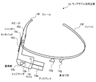
- FIG. 2 is a diagram for explaining the appearance of the wearable terminal device.
- the wearable terminal device 10 includes a display 10a, an imaging unit 10b, a shutter 10c, a touch pad 10d, a speaker 10e, a frame 10f, a nose pad unit 10g, an indicator 10h, and a microphone 10i. .
- the frame 10f is put on the ear and the nose pad portion 10g is placed on the base of the nose.
- the display 10a is attached to the frame 10f.
- the display 10a is disposed at a position where the user can visually recognize it when in use.
- the user can obtain information displayed on the display 10a in a part of the field of view.
- the display 10a may have transparency.
- the imaging unit 10b includes an image sensor such as a charge coupled device (CCD) or a complementary metal-oxide semiconductor (CMOS).
- CCD charge coupled device
- CMOS complementary metal-oxide semiconductor
- the wearable terminal device 10 can be operated using the touch pad 10d, voice commands, and blinking.
- the microphone 10i collects the command.
- a sensor mounted inside the display 10a senses blinking.
- the indicator 10h is lit or blinked when the wearable terminal device 10 is exhibiting a predetermined function (for example, an imaging function to be described later or a function for searching for a provider that provides information and services requested by the user). .
- a predetermined function for example, an imaging function to be described later or a function for searching for a provider that provides information and services requested by the user.
- a spectacle lens can be attached to the wearable terminal device 10.
- a user wearing the wearable terminal device 10 activates the main power supply of the wearable terminal device 10 and performs a predetermined operation (for example, swipes the touch pad 10d).
- a menu screen for using the functions of the wearable terminal device 10 is displayed on the side where the user's face of the display 10a is located (the back side of the display 10a in FIG. 2).
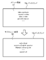
- FIG. 3 is a diagram illustrating an example of a menu screen.
- a user who takes a picture takes a video (record a video), takes a note (take a note), obtains information (get information), etc.
- the menu items that can be used are displayed.
- the menu item is selected and executed. For example, if the user wants to use the camera function of the imaging unit 10b, the imaging unit 10b takes a picture when the microphone 10i picks up the sound by pronouncing “take a picture”. Note that, during imaging using the imaging unit 10 b, for example, a shutter sound is heard from the speaker 10 e.
- the indicator 10h is turned on, and it can be seen from the surrounding people that the display 10a is turned on.
- the user can also take a picture by pressing the shutter 10c.
- the video recording time is, for example, a maximum of 10 seconds at a time.
- the user when the user wants to use the information providing function described in FIG. 1 from the menu item displayed on the menu screen 51, the user pronounces “get information” so that the microphone 10i picks up the sound and wears it.
- the terminal device 10 displays the submenu screen 52 on the display 10a.
- the microphone 10i picks up the sound by pronouncing, for example, “search a English speaker”. As shown in FIG. 1, a rectangle that can be seen through the display 10a appears around the face of the provider in a state where interpretation is possible. Then, “English OK” indicating that the interpretation service can be provided is displayed on the balloon associated with the rectangle.
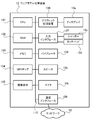
- FIG. 4 is a diagram illustrating a hardware configuration of the wearable terminal device according to the embodiment.
- the entire wearable terminal device 10 is controlled by a CPU (Central Processing Unit) 101.
- a RAM (Random Access Memory) 102 and a plurality of peripheral devices are connected to the CPU 101 via a bus 110.
- the RAM 102 is used as a main storage device of the wearable terminal device 10.
- the RAM 102 temporarily stores at least part of an OS (Operating System) program and application programs to be executed by the CPU 101.
- the RAM 102 stores various data used for processing by the CPU 101.
- the bus 110 is connected with a memory 103, a GPS chip 104, an image sensor 105, a graphic processing device 106, an input interface 107, a vibrator 108, a speaker 10e, a microphone 10i, and a communication interface 109.
- the memory 103 is a semiconductor storage device such as a flash memory.
- the memory 103 writes and reads data.
- the memory 103 stores an OS program, application programs, and various data.
- the GPS chip 104 receives radio waves emitted from GPS satellites and determines the current position (latitude and longitude). The GPS chip 104 transmits the determined current position to the CPU 101.
- the image sensor 105 captures a still image or a moving image in accordance with a command from the CPU 101.
- the captured image is stored in the RAM 102 or the memory 103 by the CPU 101.
- the graphic processor 106 is connected to a display 10a.
- the graphic processing device 105 displays an image on the screen of the display 10a in accordance with a command from the CPU 101.
- Examples of the display 10a include a liquid crystal display device.
- the input interface 107 is connected to a shutter 10c and a touch pad 10d.
- the input interface 107 transmits a signal transmitted from the shutter 10c or the touch pad 10d to the CPU 101.
- Vibrator 108 vibrates in accordance with a command from CPU 101.
- the communication interface 110 is connected to the network 50.
- the communication interface 110 transmits / receives data to / from other computers or communication devices via the network 50.
- an example of connecting directly to the network 50 has been described.
- the present invention is not limited to this, and the network 50 may be connected via another terminal device (using a tethering function). .
- FIG. 4 shows the hardware configuration of the wearable terminal device 10
- the terminal device 20 can also be realized by the same hardware configuration.
- FIG. 5 is a diagram illustrating a hardware configuration of the server apparatus according to the embodiment.
- the entire server device 30 is controlled by the CPU 301.
- a RAM 302 and a plurality of peripheral devices are connected to the CPU 301 via a bus 308.
- the RAM 302 is used as a main storage device of the server device 30.
- the RAM 302 temporarily stores at least a part of OS programs and application programs to be executed by the CPU 301.
- the RAM 302 stores various data used for processing by the CPU 301.
- the bus 308 is connected to a hard disk drive (HDD: Hard Disk Drive) 303, a graphic processing device 304, an input interface 305, a drive device 306, and a communication interface 307.
- HDD Hard Disk Drive
- the hard disk drive 303 magnetically writes and reads data to and from the built-in disk.
- the hard disk drive 303 is used as a secondary storage device of the server device 30.
- the hard disk drive 303 stores an OS program, application programs, and various data.
- a semiconductor storage device such as a flash memory can be used as the secondary storage device.
- a monitor 304 a is connected to the graphic processing device 304.
- the graphic processing device 304 displays an image on the screen of the monitor 304a in accordance with a command from the CPU 301.
- Examples of the monitor 304a include a display device using a CRT (Cathode Ray Tube), a liquid crystal display device, and the like.
- the keyboard 305a and the mouse 305b are connected to the input interface 305.
- the input interface 305 transmits a signal transmitted from the keyboard 305a or the mouse 305b to the CPU 301.
- the mouse 305b is an example of a pointing device, and other pointing devices can also be used. Examples of other pointing devices include a touch panel, a tablet, a touch pad, and a trackball.
- the drive device 306 reads data recorded on a portable recording medium such as an optical disc on which data is recorded so as to be readable by reflection of light or a USB (Universal Serial Bus) memory.
- a portable recording medium such as an optical disc on which data is recorded so as to be readable by reflection of light or a USB (Universal Serial Bus) memory.
- the drive device 306 is an optical drive device
- data recorded on the optical disc 200 is read using a laser beam or the like.
- Examples of the optical disc 200 include Blu-ray (registered trademark), DVD (Digital Versatile Disc), DVD-RAM, CD-ROM (Compact Disc Read Only Memory), CD-R (Recordable) / RW (ReWritable), and the like. .
- the communication interface 307 is connected to the network 50.
- the communication interface 307 transmits / receives data to / from other computers or communication devices via the network 50.
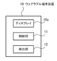
- FIG. 6 is a block diagram illustrating functions of the wearable terminal device according to the embodiment.
- the wearable terminal device 10 includes a control unit 11 and a detection unit 12.
- the control unit 11 and the detection unit 12 can be realized by the CPU 101.
- the control unit 11 controls the entire wearable terminal device 10.
- the control unit 11 has a face image recognition function. Specifically, when a face that matches the face image sent from the server device 30 is captured by the camera unit 10b and displayed on the display 10a, the control unit 11 displays the face displayed on the display 10a. The mark m1 is displayed. In addition, the control unit 11 acquires the current position of the wearable terminal device 10 from the GPS chip 104.
- the detection unit 12 performs a swipe operation, utterance, or gesture (when the user displays the menu screen 51 or the submenu screen 52 or executes a menu item displayed on the menu screen 51 or the submenu screen 52). gesture) etc. are detected.
- the detection unit 12 sends the detected information to the control unit 11.
- the control part 11 performs the process according to the detected information. For example, when a user makes an intention to provide a service to a provider, the user winks in the vicinity of the provider.
- the control unit 11 transmits an access request to the terminal device 20 possessed by the provider.
- the access request can be transmitted by using wireless communication such as Bluetooth (registered trademark).
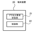
- FIG. 7 is a block diagram illustrating functions of the terminal device according to the embodiment.
- the terminal device 20 includes an access request receiving unit 21 and a control unit 22.
- the access request receiving unit 21 receives an access request issued by the wearable terminal device 10.
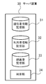
- FIG. 8 is a block diagram illustrating functions of the server device according to the embodiment.
- the server device 30 includes a provider information storage unit 31, a user information storage unit 32, a face image storage unit 33, and a control unit 34.
- the provider information storage unit 31 stores provider information.
- the provider information is information in which information related to the provider input at the time of initial registration by the provider and points obtained by the provider providing information to the user are associated with each other.
- FIG. 9 is a diagram for explaining the provider information.
- the provider information is stored as a table.
- the table T1 shown in FIG. 9 includes columns for provider terminal ID, face image ID, name, address, sex, age, occupation, provision, language, state, and points. Information arranged in the horizontal direction is associated with each other.
- the provider terminal ID column an ID unique to each terminal device assigned to each terminal device 20 possessed by the provider is set.
- face image ID column an ID for identifying the face image of the provider is set.
- the name column the name of the provider input by the provider at the time of initial registration is set.
- the address of the provider input by the provider at the time of initial registration is set in the address column.
- the sex column the sex of the provider input by the provider at the time of initial registration is set.
- the age column the age of the provider input by the provider at the time of initial registration is set.
- the column of occupation the occupation of the provider input by the provider at the initial registration is set.
- Information food guidance, venue guidance, interpretation, etc.
- the language column one or more languages that can be supported by the provider input by the provider at the time of initial registration are set.
- Information for identifying whether or not the terminal device 20 is in a standby state in which information can be provided is set in the status column. Note that the state may be set for each provided content.
- points column points (total values) obtained by providing information to the user by the provider are set.
- User information is stored in the user information storage unit 32.
- the user information is information in which information described in the presented passport when the user rents the wearable terminal device 10 is associated with a point received when the provider provides information to the user.
- FIG. 10 is a diagram illustrating user information.
- user information is stored in a table.
- the table T2 shown in FIG. 10 includes columns for user terminal ID, name, nationality, language, gender, age, passport number, and points. Information arranged in the horizontal direction is associated with each other.
- an ID unique to the wearable terminal device assigned to each wearable terminal device 10 is set. For example, when the user loses the wearable terminal device, it is possible to identify which wearable terminal device is lost by looking at the user terminal ID.
- the name of the user is set in the name column.
- the nationality of the user is set in the nationality column.
- One or more languages spoken by the user are set in the language column.
- the sex of the user is set in the gender column.
- the age of the user is set in the age column.
- a passport number possessed by the user is set.
- points possessed by the user are set.
- the points may include initial points when the wearable terminal device 10 is rented. When points are lost, points can be purchased by credit card payment.
- the face image storage unit 33 stores the face image of the provider in association with the face image ID. As described above, since the provider terminal ID and the face image ID are stored in association with each other in the table T1, the provider terminal ID and the face image are substantially associated with each other.
- control unit 34 transmits information about a provider that can provide information requested by the user to the wearable terminal device 10.
- control unit 33 manages the exchange of points between the user and the provider performed when providing information.
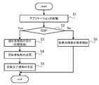
- FIG. 11 is a flowchart for explaining the initial setting process of the provider.
- the provider operates the terminal device 20 to access a predetermined website via the network 50, thereby FIG. 7. Download an application with the information provision function shown.
- Step S1 The terminal device 20 starts an application by the operation of the provider.
- the control unit 22 starts operating, and the process proceeds to step S2.
- Step S2 The control unit 22 determines whether it is the first activation. If it is the first activation (Yes in step S2), the process proceeds to step S3. If it is not the first activation, that is, if it is the second activation or later (No in step S2), the process proceeds to step S6.
- Step S3 The control unit 22 displays a registration screen on the monitor of the terminal device 20, and accepts input of provider information (initial registration). Moreover, the control part 22 receives the input of a provider's face image using the image pick-up element with which the terminal device 20 is provided. When the provider information and the face image are input by the provider and the transmission button is pressed, the process proceeds to step S4.
- Step S ⁇ b> 4 The control unit 22 transmits the provider information and the face image to the server device 30 in association with the provider terminal ID. Then, the process proceeds to step S5.
- the server device 30 stores the received provider information in the table T1. In addition, the server device 30 generates a unique face image ID.
- the received face image and the generated face image ID are stored in the face image storage unit 33 in association with the provider terminal ID.
- the generated face image ID is also stored in the table T1 in association with the provider terminal ID.
- Step S5 When the control unit 22 receives the notification that the provider information is stored in the table T1 from the server device 30, the control unit 22 notifies the provider using the speaker or the vibrator function. Then, the process shown in FIG. 11 is complete
- Step S ⁇ b> 6 The control unit 22 notifies the server device 30 of the standby state in association with the provider terminal ID. Then, the process shown in FIG. 11 is complete
- the provider can change the contents of the provider information stored in the server device 30 at an arbitrary timing by starting the application.
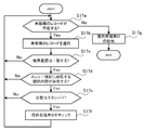
- FIG. 12 is a flowchart for explaining processing for displaying a mark around the face of the provider.
- the control unit 11 displays the menu screen 51 on the display 10a by a predetermined operation or operation of the user.
- Step S12 When the menu item “get information” is selected by the user, the control unit 11 displays the submenu screen 52 on the display 10a.
- Step S ⁇ b> 13 When any menu item is selected by the user from among the menu items displayed on the submenu screen 52, the control unit 11 transmits selection information to the server device 30.
- This selection information includes the user terminal ID of the wearable terminal device 10, the position information of the wearable terminal device 10, the menu item selected by the user, and the language used by the user. Note that the position information of the wearable terminal device 10 is acquired from the GPS chip 104 by the control unit 11.
- the control unit 34 proceeds to step S15.
- Step S15 The control unit 34 extracts position information included in the selection information. Thereafter, the process proceeds to operation S16.
- Step S16 The control unit 34 makes an inquiry to a GPS server device (not shown) to determine the provider terminal ID of the terminal device 20 located in the vicinity (for example, within 10 m) of the position information extracted in Step S15. Thereafter, the process proceeds to operation S17.
- Step S17 The control unit 34 extracts the provider terminal ID of the provider that can provide the information desired by the user using the provider terminal ID of the terminal device 20 determined in step S16 and the selection information. To do. Thereafter, the process proceeds to operation S18. This extraction process will be described in detail later.
- the control unit 34 refers to the table T1 and identifies the face image ID associated with the provider terminal ID extracted in step S17. Then, the control unit 34 refers to the face image storage unit 33 and extracts a face image associated with the specified face image ID. Then, information that associates the provider terminal ID, the extracted face image, and the menu item (hereinafter referred to as “extraction information”) is transmitted to the wearable terminal device 10.
- Step S ⁇ b> 19 Upon receiving the extraction information from the server device 30, the control unit 11 determines whether a face that matches the face image included in the received extraction information is captured by the camera unit 10 b (face authentication). . When a face that matches the face image is captured by the camera unit 10b, the control unit 11 displays the mark m1 so as to surround the face displayed on the display 10a. Then, a word indicating that the service corresponding to the menu item selected by the user can be provided is displayed on the balloon associated with the mark m1. This is the end of the description of the processing illustrated in FIG.
- step S12 After the process of step S12 is performed by the user, the processes of step S13 to step S19 may be repeatedly executed. Thereby, even when the user or the provider moves, the service provider existing in the vicinity of the user can be specified along with the movement.
- step S17 Next, the extraction process of the provider terminal ID in step S17 will be described in detail.
- FIG. 13 is a flowchart for explaining the extraction process of the provider terminal ID.
- Step S17a The control unit 34 refers to the table T1, and among the records in the table T1 including the provider terminal ID of the terminal device 20 determined in step S16, the unprocessed records (the processes of steps S17a to S17e are performed). It is determined whether or not there is a record that has not been performed. If there is an unprocessed record (Yes in step S17a), the process proceeds to step S17b. When there is no unprocessed record (No in step S17a), the process proceeds to step S17g. [Step S ⁇ b> 17 b] The control unit 34 selects one unprocessed record. Thereafter, the process proceeds to operation S17c.
- Step S17c The control unit 34 determines whether or not the language set in the language field of the record selected in Step S17b matches the language used in the received selection information. When the language set in the language column matches the language used in the received selection information (Yes in step S17c), the process proceeds to step S17d. If the language set in the language column does not match the language used in the received selection information (No in step S17c), the process proceeds to step S17a.
- Step S17d The control unit 34 determines whether or not the provision content set in the provision column of the record selected in Step S17b matches the menu item included in the received selection information. For example, if the menu item included in the selection information is “search a English speaker”, it is determined that “interpretation” is set. If the menu item is “venue guide”, “guidance” is set, it is determined that they match.
- the provision content set in the provision column matches the menu item included in the received selection information (Yes in step S17d)
- the process proceeds to step S17e.
- the provision content set in the provision column does not match the menu item included in the received selection information (No in step S17d)
- the process proceeds to step S17a.
- Step S17e The control unit 34 determines whether or not the state set in the state column of the record selected in step S17b is standby. When the state is standby (Yes in step S17e), the process proceeds to step S17f. When the state is not standby (No in step S17e), the process proceeds to step S17a. [Step S17f] The control unit 34 checks the provider terminal ID of the record. Then, the process proceeds to step S17a. [Step S17g] The control unit 34 extracts all provider terminal IDs checked in step S17f. Then, the process shown in FIG. 13 is complete
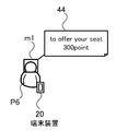
- FIG. 14 is a diagram illustrating an example of marks displayed on the display.
- the menu item displayed on the submenu screen 52 includes a menu item for searching for a seat (search a seat).
- search a seat a menu item for searching for a seat
- the wearable terminal device 10 and the server device 30 execute the process shown in FIG.
- the control unit 11 performs setting that the seat may be given, and displays the mark m1 on the display 10a so as to surround the face of the provider P6 possessing the terminal device 20 in the standby state.
- the balloon 44 associated with the rectangle displays “to offer your seat” indicating that the seat can be transferred, and the point “300 points” requested by the provider P6 to the user when the seat is transferred.
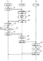
- FIG. 15 is a diagram illustrating processing when the service providing system is used for seat transfer.
- Step S21 When the detection unit 12 detects that the user has performed a predetermined operation, the control unit 11 transmits an access request to the terminal device 20 possessed by the provider P6.
- the access request can be received only by the terminal device 20 in the standby state possessed by the provider whose mark m1 is displayed on the display 10a. In other words, even if there is another terminal device 20 in the standby state, it is possessed by the provider who provides the provision contents that are not displayed on the display 10a of the user (which the user does not want).
- the terminal device 20 does not receive the access request.
- Step S22 When the access request receiving unit 21 receives the access request, the process proceeds to step S23.
- Step S23 The control unit 22 notifies the provider that the access request has been received by a vibrator function, a voice function, or the like. Thereafter, the process proceeds to operation S24.
- Step S ⁇ b> 24 By the operation of the provider, the control unit 22 transmits to the wearable terminal device 10 a point request for requesting transfer of points.
- Step S25 Upon receiving the point request, the control unit 11 proceeds to step S26.
- Step S26 The control unit 11 displays a confirmation screen on the display 10a as to whether 300 points may be transferred to the provider P6. And it waits for a user's predetermined operation
- movement for example, wink.
- Step S27 The control unit 11 transmits a point approval to the terminal device 20.
- This point approval includes the user terminal ID of the wearable terminal device 10 and points to be transferred (300 points in this specific example).
- Step S28 When the control unit 22 confirms reception of the point approval, the process proceeds to step S29. At this time, the control unit 22 may notify the provider that the point approval has been received by a vibrator function, a voice function, or the like.
- Step S ⁇ b> 29 The control unit 22 transmits a point movement request to the server device 30.
- the provider terminal ID of the terminal device 20 possessed by the provider P6 is added to the user terminal ID of the wearable terminal device 10 included in the point approval received in step S28 and the 300 points to be transferred. include.
- Step S30 Upon confirming reception of the point movement request, the control unit 34 proceeds to step S31.
- the control unit 34 refers to the table T2, and is set in the point column of the record including the user terminal ID that matches the user terminal ID included in the point movement request received in step S30. Reduce points by 300 points. Further, the control unit 34 refers to the table T2 and sets the points set in the point column of the record having the provider terminal ID that matches the provider terminal ID included in the point movement request received in step S30. Increase by 300 points. Thereafter, the process proceeds to operation S32. [Step S ⁇ b> 32] The control unit 34 transmits a point movement completion notification to the wearable terminal device 10 and the terminal device 20.
- step S28 the time of confirming that point approval was received in step S28.
- the seat may be given to the user when it is confirmed in step S32 that the point movement completion notification has been received.
- the example of moving the point when giving up the seat has been described, but whether or not to move the point may be arbitrary. For example, by displaying only “to offer your seat” in the balloon 44, it is possible to display an intention to provide a seat free of charge. This can be determined when the provider inputs the provider information.
- a healthy person may request 300 points to give up a seat, but for a pregnant woman, a disabled person, or a user with a disability, the balloon 44 may display a condition such as not requiring a point. it can.
- a condition such as not requiring a point. it can.
- the menu item displayed on the submenu screen 52 includes an Olympic venue guide (Olympic venue guide).
- the control unit 11 When the user pronounces “Olympic venue guide” and the microphone 10i picks up the sound, the control unit 11 performs a process shown in FIG.
- the mark m1 is displayed on the display 10a so as to surround the face of the provider performed using the No. 20.
- the balloon associated with the mark m1 displays “Olympic venue ⁇ guide ”indicating that the route guidance can be performed and the point“ 100 points ”requested by the provider to the user at the time of transfer.
- the user When requesting directions from this provider, the user performs a predetermined action (for example, wink) in front of the provider. Thereby, the process shown in FIG. 14 is started, and points are transferred.
- a predetermined action for example, wink
- the provider guides the user to the Olympic venue.
- the provider guides the user to the Olympic venue.
- the service providing system 1 can be used. It is possible to easily find a provider who can speak a person's language.
- the provider that provides the service desired by the user can be visually found using the wearable terminal device 10. For this reason, the possibility that the user can enjoy the service can be further increased.
- the transfer of points may be set arbitrarily.
- the service providing system 1 can be used for a commercial purpose or can be used for a non-profit purpose.
- the user can be a provider by possessing both the wearable terminal device 10 and the terminal device 20.
- the user can enjoy the service from the other party while providing the service to the other party (exchange of value and value).
- Communicating with each other is necessary to exchange services. “Communication of visual information” plays a major role in communication. “Viewpoint” and “immediateness” are important for visual information. According to the service providing system 1, a provider who provides a service desired by the user can be visually found using the wearable terminal device 10 (in contrast, a service that the user does not want is provided. The provider is not found). For this reason, the synchronism of the sender's viewpoint and empathy is transmitted directly and realistically to the receiver.
- the position of wearable terminal device 10 or terminal device 20 is specified using GPS has been described.
- the present invention is not limited to this, and for example, the location is specified using a base station of a mobile terminal device. You may make it do.
- the method for identifying a provider by recognizing a face has been described as an example.
- the method for identifying a provider is not limited to this.
- the terminal device 20 may have a part of the functions of the server device 30, or the server device 30 may have a part of the functions of the terminal device 20.
- the wearable terminal device, display method, program, and service providing system of the present invention have been described based on the illustrated embodiment.
- the present invention is not limited to this, and the configuration of each unit is the same. It can be replaced with any configuration having the above function.
- other arbitrary structures and processes may be added to the present invention.
- the present invention may be a combination of any two or more configurations (features) of the above-described embodiments.
- the above processing functions can be realized by a computer.
- a program describing the processing contents of the functions of the wearable terminal device 10 is provided.
- the program describing the processing contents can be recorded on a computer-readable recording medium.
- the computer-readable recording medium include a magnetic storage device, an optical disk, a magneto-optical recording medium, and a semiconductor memory.
- the magnetic storage device include a hard disk drive, a flexible disk (FD), and a magnetic tape.
- the optical disc include a DVD, a DVD-RAM, and a CD-ROM / RW.
- the magneto-optical recording medium include MO (Magneto-Optical disk).
- the computer that executes the program stores, for example, the program recorded on the portable recording medium or the program transferred from the server computer in its own storage device. Then, the computer reads the program from its own storage device and executes processing according to the program. The computer can also read the program directly from the portable recording medium and execute processing according to the program. In addition, each time a program is transferred from a server computer connected via a network, the computer can sequentially execute processing according to the received program.
- processing functions described above can be realized by an electronic circuit such as a DSP (Digital Signal Processor), an ASIC (Application Specific Integrated Circuit), or a PLD (Programmable Logic Device).
- DSP Digital Signal Processor
- ASIC Application Specific Integrated Circuit
- PLD Programmable Logic Device
Abstract
Description
に関する。 The present invention relates to a wearable terminal device, a display method, a program, and a service providing system.
1つの側面では、本発明は、利用者が要求する情報を提供できる提供者を、他のプライバシーを侵害せず、特定することを目的とする。 By the way, the number of foreign travelers to Japan tends to increase year by year. In 2013, more than 10 million foreigners came to Japan every year. In particular, it is decided that the Olympics will be held in Tokyo in 2020, and it is expected that many foreigners will enter Japan for the purpose of watching Olympic games during that period. It is convenient if a foreigner who has entered Japan can enjoy the desired service by using the wearable terminal device. The same applies to various other cases as well as the Olympics.
In one aspect, the present invention aims to identify a provider who can provide information requested by a user without infringing on other privacy.
<実施の形態>
図1は、実施の形態のサービス提供システムを示す図である。 Hereinafter, a service providing system according to an embodiment will be described in detail with reference to the drawings.
<Embodiment>
FIG. 1 is a diagram illustrating a service providing system according to an embodiment.
なお、サーバ装置30は国内に設置されていてもよいし、国外に設置されていてもよい。 A foreigner (hereinafter referred to as a user) who has landed at the airport (or port) carries his legs to a predetermined counter provided in the airport. A wearable terminal device (computer) 10 corresponding to the language used by the user is prepared in the counter. The user rents the
The
また、吹き出しには、提供者の名前、年齢、職種等の情報が表示されるようになっていてもよい。
以下、開示のサービス提供システムをより具体的に説明する。
図2は、ウェアラブル端末装置の外観を説明する図である。 Further, when there are a plurality of providers who provide the service desired by the user, a predetermined rule may be provided so that the priority can be identified on the display. For example, a more detailed condition (gender, age, etc.) can be set, and a green mark m1 is displayed for a provider that satisfies the condition, and a service desired by the user that does not satisfy the detailed condition is displayed. The yellow mark m1 may be displayed on the provider who provides the information.
In addition, information such as the name, age, and job type of the provider may be displayed in the balloon.
Hereinafter, the disclosed service providing system will be described more specifically.
FIG. 2 is a diagram for explaining the appearance of the wearable terminal device.
利用者がウェアラブル端末装置10を装着する場合は、フレーム10fを耳にかけ、鼻当て部10gを鼻の付け根に載せる。 The wearable
When the user wears the wearable
利用者は、ディスプレイ10aが透過性を有している場合は直接、または撮像部10bを介して周りの景色を見ることができる。
ウェアラブル端末装置10の操作はタッチパッド10dと音声コマンド、まばたきを利用して行うことができる。 The
When the
The wearable
なお、他人はディスプレイ10aのオン/オフは判断できるが、利用者が何をやっているかまでは周りの人は分からないようになっている。
なお、図2には図示していないが、ウェアラブル端末装置10には眼鏡レンズを装着することもできる。 The
Others can determine whether the
Although not shown in FIG. 2, a spectacle lens can be attached to the wearable
図3は、メニュー画面の一例を示す図である。 A user wearing the wearable
FIG. 3 is a diagram illustrating an example of a menu screen.
また、利用者がシャッター10cを押下することによっても写真を撮ることが可能である。動画の撮影時間は、例えば1回最長10秒である。 On the
The user can also take a picture by pressing the
次に、ウェアラブル端末装置10、端末装置20、およびサーバ装置30のハードウェア構成を説明する。
図4は、実施の形態のウェアラブル端末装置のハードウェア構成を説明する図である。 It should be noted that the user can see the information of all the providers providing some information via the
Next, the hardware configuration of the wearable
FIG. 4 is a diagram illustrating a hardware configuration of the wearable terminal device according to the embodiment.
バイブレータ108は、CPU101からの命令に従って、振動する。 The
図5は、実施の形態のサーバ装置のハードウェア構成を説明する図である。 With the hardware configuration as described above, the processing functions of the present embodiment can be realized. Although FIG. 4 shows the hardware configuration of the wearable
FIG. 5 is a diagram illustrating a hardware configuration of the server apparatus according to the embodiment.
以上のようなハードウェア構成によって、本実施の形態の処理機能を実現することができる。
図4に示すようなハードウェア構成のウェアラブル端末装置10内には、以下のような機能が設けられる。
図6は、実施の形態のウェアラブル端末装置の機能を示すブロック図である。
ウェアラブル端末装置10は、制御部11と、検出部12とを有している。なお、制御部11と検出部12とはCPU101により実現することができる。 The
With the hardware configuration as described above, the processing functions of the present embodiment can be realized.
The following functions are provided in the wearable
FIG. 6 is a block diagram illustrating functions of the wearable terminal device according to the embodiment.
The wearable
図7は、実施の形態の端末装置の機能を示すブロック図である。
端末装置20は、アクセス要求受信部21と、制御部22とを有している。
アクセス要求受信部21は、ウェアラブル端末装置10が発するアクセス要求を受信する。 The
FIG. 7 is a block diagram illustrating functions of the terminal device according to the embodiment.
The
The access
図8は、実施の形態のサーバ装置の機能を示すブロック図である。
サーバ装置30は、提供者情報記憶部31と、利用者情報記憶部32と、顔画像記憶部33と、制御部34とを有している。 The
FIG. 8 is a block diagram illustrating functions of the server device according to the embodiment.
The
図9は、提供者情報を説明する図である。 The provider
FIG. 9 is a diagram for explaining the provider information.
提供者端末IDの欄には、提供者が所持する端末装置20毎に割り振られた端末装置固有のIDが設定される。
顔画像IDの欄には、提供者の顔画像を識別するIDが設定される。
氏名の欄には、初期登録時に提供者が入力した提供者の氏名が設定される。
住所の欄には、初期登録時に提供者が入力した提供者の住所が設定される。
性別の欄には、初期登録時に提供者が入力した提供者の性別が設定される。
年齢の欄には、初期登録時に提供者が入力した提供者の年齢が設定される。
職業の欄には、初期登録時に提供者が入力した提供者の職業が設定される。
提供の欄には、初期登録時に提供者が入力した提供者が提供できる情報(食べ物案内、会場案内、通訳等)が設定される。
言語の欄には、初期登録時に提供者が入力した提供者が対応できる言語が1つまたは複数設定される。 In the present embodiment, the provider information is stored as a table. The table T1 shown in FIG. 9 includes columns for provider terminal ID, face image ID, name, address, sex, age, occupation, provision, language, state, and points. Information arranged in the horizontal direction is associated with each other.
In the provider terminal ID column, an ID unique to each terminal device assigned to each
In the face image ID column, an ID for identifying the face image of the provider is set.
In the name column, the name of the provider input by the provider at the time of initial registration is set.
The address of the provider input by the provider at the time of initial registration is set in the address column.
In the sex column, the sex of the provider input by the provider at the time of initial registration is set.
In the age column, the age of the provider input by the provider at the time of initial registration is set.
In the column of occupation, the occupation of the provider input by the provider at the initial registration is set.
Information (food guidance, venue guidance, interpretation, etc.) that can be provided by the provider input at the time of initial registration is set in the provision column.
In the language column, one or more languages that can be supported by the provider input by the provider at the time of initial registration are set.
ポイントの欄には、提供者が利用者に情報を提供することにより得たポイント(合計値)が設定される。
再び図8に戻って説明する。 Information for identifying whether or not the
In the points column, points (total values) obtained by providing information to the user by the provider are set.
Returning again to FIG.
図10は、利用者情報を説明する図である。 User information is stored in the user
FIG. 10 is a diagram illustrating user information.
氏名の欄には、利用者の氏名が設定される。
国籍の欄には、利用者の国籍が設定される。
言語の欄には、利用者が話す言語が1つまたは複数設定される。
性別の欄には、利用者の性別が設定される。
年齢の欄には、利用者の年齢が設定される。
パスポート番号の欄には、利用者が所持するパスポート番号が設定される。 In the user terminal ID column, an ID unique to the wearable terminal device assigned to each wearable
The name of the user is set in the name column.
The nationality of the user is set in the nationality column.
One or more languages spoken by the user are set in the language column.
The sex of the user is set in the gender column.
The age of the user is set in the age column.
In the passport number column, a passport number possessed by the user is set.
再び図8に戻って説明する。 In the point column, points possessed by the user are set. For example, the points may include initial points when the wearable
Returning again to FIG.
次に、提供者の初期設定処理を、フローチャートを用いて説明する。
図11は、提供者の初期設定処理を説明するフローチャートである。 In response to a request for information provision from the wearable
Next, the initial setting process of the provider will be described using a flowchart.
FIG. 11 is a flowchart for explaining the initial setting process of the provider.
[ステップS4] 制御部22は、提供者情報および顔画像を提供者端末IDに関連づけてサーバ装置30に送信する。その後、ステップS5に遷移する。 [Step S3] The
[Step S <b> 4] The
なお、提供者は、アプリケーションを起動することで任意のタイミングでサーバ装置30に記憶されている提供者情報の内容を変更することができる。
次に、ディスプレイ10aを介して見ることができるマークm1を提供者の顔の周りに表示させる処理を、フローチャートを用いて説明する。
図12は、マークを提供者の顔の周りに表示させる処理を説明するフローチャートである。
[ステップS11] 利用者の所定の動作又は操作により、制御部11は、メニュー画面51をディスプレイ10aに表示する。 [Step S <b> 6] The
The provider can change the contents of the provider information stored in the
Next, processing for displaying the mark m1 that can be seen through the
FIG. 12 is a flowchart for explaining processing for displaying a mark around the face of the provider.
[Step S11] The
[ステップS14] 制御部34は、選択情報を受信するとステップS15に遷移する。
[ステップS15] 制御部34は、選択情報に含まれる位置情報を取り出す。その後、ステップS16に遷移する。 [Step S <b> 13] When any menu item is selected by the user from among the menu items displayed on the
[Step S14] Upon receiving the selection information, the
[Step S15] The
以上で図12に示す処理の説明を終了する。 [Step S <b> 19] Upon receiving the extraction information from the
This is the end of the description of the processing illustrated in FIG.
次に、ステップS17の提供者端末IDの抽出処理を詳しく説明する。
図13は、提供者端末IDの抽出処理を説明するフローチャートである。 Note that after the process of step S12 is performed by the user, the processes of step S13 to step S19 may be repeatedly executed. Thereby, even when the user or the provider moves, the service provider existing in the vicinity of the user can be specified along with the movement.
Next, the extraction process of the provider terminal ID in step S17 will be described in detail.
FIG. 13 is a flowchart for explaining the extraction process of the provider terminal ID.
[ステップS17b] 制御部34は、未処理のレコードを1つ選択する。その後、ステップS17cに遷移する。 [Step S17a] The
[Step S <b> 17 b] The
[ステップS17f] 制御部34は、当該レコードの提供者端末IDをチェックする。その後、ステップS17aに遷移する。
[ステップS17g] 制御部34は、ステップS17fにてチェックされた全ての提供者端末IDを抽出する。その後、図13に示す処理を終了する。
なお、ステップS17c~17eの処理の順序は、図13に示す方法に限定されない。また、提供者端末IDの抽出方法は、図13に示す方法に限定されない。
<応用例1>
次に、図12に示す処理を、電車内の座席の譲渡に用いた場合について説明する。
図14は、ディスプレイに表示されるマークの一例を示す図である。 [Step S17e] The
[Step S17f] The
[Step S17g] The
Note that the processing order of steps S17c to 17e is not limited to the method shown in FIG. Further, the method of extracting the provider terminal ID is not limited to the method shown in FIG.
<Application example 1>
Next, the case where the process shown in FIG. 12 is used for transfer of seats in a train will be described.
FIG. 14 is a diagram illustrating an example of marks displayed on the display.
図15は、サービス提供システムを座席の譲渡に用いた場合の処理を説明する図である。 When the user wishes to transfer the seat from the provider P6, the user performs a predetermined operation (for example, wink) in front of the provider P6. Hereinafter, processing after a predetermined operation will be described with reference to the drawings.
FIG. 15 is a diagram illustrating processing when the service providing system is used for seat transfer.
[ステップS22] アクセス要求受信部21がアクセス要求を受信すると、ステップS23に遷移する。 [Step S21] When the
[Step S22] When the access
[ステップS24] 提供者の操作により、制御部22は、ポイントの譲渡を要求するポイント請求をウェアラブル端末装置10に送信する。
[ステップS25] 制御部11は、ポイント請求を受信すると、ステップS26に遷移する。 [Step S23] The
[Step S <b> 24] By the operation of the provider, the
[Step S25] Upon receiving the point request, the
[ステップS30] 制御部34は、ポイント移動請求の受信を確認すると、ステップS31に遷移する。 [Step S <b> 29] The
[Step S30] Upon confirming reception of the point movement request, the
[ステップS32] 制御部34は、ポイント移動完了通知をウェアラブル端末装置10および端末装置20に送信する。 [Step S31] The
[Step S <b> 32] The
<応用例2>
次に、図12に示す処理を、オリンピック会場への案内に用いた場合について説明する。 Various additional conditions may be added to the provision column. For example, a healthy person may request 300 points to give up a seat, but for a pregnant woman, a disabled person, or a user with a disability, the
<Application example 2>
Next, the case where the process shown in FIG. 12 is used for guidance to the Olympic venue will be described.
また、本実施の形態では、顔を認識することにより、提供者を特定する方法を例に説明したが、提供者を特定する方法は、これに限定されない。
また、サーバ装置30の機能の一部を端末装置20が持つようにしてもよいし、端末装置20が持つ機能の一部をサーバ装置30が持つようにしてもよい。 In this embodiment, the case where the position of wearable
In the present embodiment, the method for identifying a provider by recognizing a face has been described as an example. However, the method for identifying a provider is not limited to this.
Further, the
また、本発明は、前述した各実施の形態のうちの、任意の2以上の構成(特徴)を組み合わせたものであってもよい。 The wearable terminal device, display method, program, and service providing system of the present invention have been described based on the illustrated embodiment. However, the present invention is not limited to this, and the configuration of each unit is the same. It can be replaced with any configuration having the above function. Moreover, other arbitrary structures and processes may be added to the present invention.
Further, the present invention may be a combination of any two or more configurations (features) of the above-described embodiments.
10 ウェアラブル端末装置
10a ディスプレイ
11 制御部
12 検出部
20 端末装置
21 アクセス要求受信部
22 制御部
30 サーバ装置
31 提供者情報記憶部
32 利用者情報記憶部
33 顔画像記憶部
34 制御部
41~44 吹き出し
51 メニュー画面
52 サブメニュー画面
m1 マーク
T1、T2 テーブル DESCRIPTION OF SYMBOLS 1
Claims (13)
- 使用時に利用者の視認可能な位置に配置されるディスプレイと、
所定のサービスの享受を希望する際に利用者が実行する所定の動作または操作を検出する検出部と、
前記検出部の検出に応じて、前記ディスプレイに表示される人のうち、前記所定のサービスを提供する提供者を識別可能な情報を、前記ディスプレイに表示する表示部と、
を備えることを特徴とするウェアラブル端末装置。 A display placed in a position that is visible to the user when in use,
A detection unit that detects a predetermined operation or operation performed by a user when the user wishes to enjoy a predetermined service;
A display unit that displays information that can identify a provider that provides the predetermined service among the people displayed on the display in response to detection by the detection unit;
A wearable terminal device comprising: - 前記表示部は、前記検出部の検出に応じて利用者がサービスの享受を依頼できる複数のメニュー項目を前記ディスプレイに表示し、利用者により選択されたメニュー項目のサービスを享受させる提供者を識別可能な情報を、前記ディスプレイに表示する請求項1に記載のウェアラブル端末装置。 The display unit displays, on the display, a plurality of menu items that can be requested by a user to receive a service in response to detection by the detection unit, and identifies a provider that receives the service of the menu item selected by the user The wearable terminal device according to claim 1, wherein possible information is displayed on the display.
- 前記提供者は、端末装置を所持しており、
当該ウェアラブル端末装置の近傍に存在する端末装置を所持する提供者の顔画像を受信し、受信した顔画像を用いて顔認証を行い前記所定のサービスを提供する提供者を特定する請求項1または2に記載のウェアラブル端末装置。 The provider has a terminal device,
The face image of the provider who possesses the terminal device that exists in the vicinity of the wearable terminal device is received, face authentication is performed using the received face image, and the provider that provides the predetermined service is specified. The wearable terminal device according to 2. - 利用者が選択した提供者に解決を依頼する動作または操作を前記提供者の近傍で行ったことを前記検出部が検出すると、前記提供者が所持する端末装置が受信可能な信号を発信する発信部をさらに備える請求項1ないし3のいずれかに記載のウェアラブル端末装置。 When the detection unit detects that an operation or an operation for requesting a solution selected by a provider is performed in the vicinity of the provider, a transmission for transmitting a signal that can be received by the terminal device possessed by the provider The wearable terminal device according to claim 1, further comprising a unit.
- 前記表示部は、前記ディスプレイに表示される提供者の近傍に前記提供者の詳細情報を表示する請求項1ないし4のいずれかに記載のウェアラブル端末装置。 The wearable terminal device according to any one of claims 1 to 4, wherein the display unit displays detailed information of the provider in the vicinity of the provider displayed on the display.
- 前記検出部の検出に応じて、点灯または点滅するインジケータを備える請求項1ないし5のいずれかに記載のウェアラブル端末装置。 The wearable terminal device according to any one of claims 1 to 5, further comprising an indicator that lights or blinks in accordance with detection by the detection unit.
- コンピュータが、
所定のサービスの享受を希望する際に利用者が実行する所定の動作または操作を検出し、
検出に応じて、使用時に利用者の視認可能な位置に配置されるディスプレイに表示される人のうち、前記所定のサービスを提供する提供者を識別可能な情報を、前記ディスプレイに表示する、
ことを特徴とする表示方法。 Computer
Detects certain actions or operations performed by users when they wish to enjoy certain services,
In response to the detection, information that can identify the provider providing the predetermined service among the people displayed on the display arranged at the position where the user can visually recognize the user is displayed on the display.
A display method characterized by that. - コンピュータに、
所定のサービスの享受を希望する際に利用者が実行する所定の動作または操作を検出し、
検出に応じて、使用時に利用者の視認可能な位置に配置されるディスプレイに表示される人のうち、前記所定のサービスを提供する提供者を識別可能な情報を、前記ディスプレイに表示する、
処理を実行させることを特徴とするプログラム。 On the computer,
Detects certain actions or operations performed by users when they wish to enjoy certain services,
In response to the detection, information that can identify the provider providing the predetermined service among the people displayed on the display arranged at the position where the user can visually recognize the user is displayed on the display.
A program characterized by causing processing to be executed. - 使用時に利用者の視認可能な位置に配置されるディスプレイと、所定のサービスの享受を希望する際に利用者が実行する所定の動作または操作を検出する検出部と、前記検出部の検出に応じて、前記ディスプレイに表示される人のうち、前記所定のサービスを提供する提供者を識別可能な情報を、前記ディスプレイに表示する表示部と、を備えるウェアラブル端末装置と、
提供者が利用者に対し提供できるサービスを含む提供者情報を記憶する記憶部と、前記ウェアラブル端末装置からの前記所定のサービスの享受要求に基づき前記記憶部に記憶された提供者情報を用いて前記所定のサービスを提供する提供者を識別可能な情報を作成し、前記ウェアラブル端末装置に送信する送信部と、を備えるサーバ装置と、
を有することを特徴とするサービス提供システム。 A display arranged at a position that is visible to the user when in use, a detection unit that detects a predetermined operation or operation performed by the user when he / she wants to enjoy a predetermined service, and according to detection by the detection unit A wearable terminal device comprising: a display unit configured to display information capable of identifying a provider providing the predetermined service among the people displayed on the display;
Using a storage unit that stores provider information including services that can be provided to users by a provider, and provider information stored in the storage unit based on a request to enjoy the predetermined service from the wearable terminal device A server device comprising: a transmission unit that creates information capable of identifying a provider providing the predetermined service and transmits the information to the wearable terminal device;
A service providing system comprising: - 前記サーバ装置は、利用者および提供者が所持するポイントを記憶する記憶部をさらに有し、
提供者が前記所定のサービスを提供する際に前記記憶部に記憶される利用者が所持するポイントのうち所定のポイントを提供者に移動させる処理を行う請求項9に記載のサービス提供システム。 The server device further includes a storage unit that stores points possessed by the user and the provider,
The service providing system according to claim 9, wherein when the provider provides the predetermined service, a process of moving a predetermined point among points stored by the user stored in the storage unit to the provider is performed. - 前記提供者情報には前記提供者がサービスを提供可能な状態か否かが記憶されており、
前記サーバ装置は、前記ウェアラブル端末装置からの前記所定のサービスの享受要求に基づき前記記憶部に記憶された提供者情報のうち、サービスを提供可能な状態の提供者情報を用いて前記所定のサービスを提供する提供者を識別可能な情報を作成し、前記ウェアラブル端末装置に送信する請求項9または10に記載のサービス提供システム。 The provider information stores whether or not the provider can provide a service.
The server device uses the provider information stored in the storage unit based on the request for enjoying the predetermined service from the wearable terminal device, using the provider information in a state where the service can be provided. The service providing system according to claim 9 or 10, wherein information capable of identifying a provider that provides information is created and transmitted to the wearable terminal device. - 前記ウェアラブル端末装置は、任意のタイミングでアプリケーションをダウンロードすることにより前記検出部および前記表示部の機能を実装する請求項9ないし11のいずれかに記載のサービス提供システム。 12. The service providing system according to claim 9, wherein the wearable terminal device implements the functions of the detection unit and the display unit by downloading an application at an arbitrary timing.
- 前記提供者は、端末装置を所持しており、
前記サーバ装置は、提供者の顔画像を前記端末装置の識別情報と実質的に関連づけて記憶する記憶部をさらに有し、
前記サーバ装置は、前記ウェアラブル端末装置の近傍に存在する端末装置を所持する提供者の顔画像を前記ウェアラブル端末装置に送信し、
前記ウェアラブル端末装置は、受信した顔画像を用いて顔認証を行い前記所定のサービスを提供する提供者を特定する請求項9ないし12のいずれかに記載のサービス提供システム。
The provider has a terminal device,
The server device further includes a storage unit that stores the face image of the provider substantially in association with the identification information of the terminal device,
The server device transmits a face image of a provider having a terminal device existing in the vicinity of the wearable terminal device to the wearable terminal device,
13. The service providing system according to claim 9, wherein the wearable terminal device performs face authentication using the received face image and identifies a provider that provides the predetermined service.
Priority Applications (6)
| Application Number | Priority Date | Filing Date | Title |
|---|---|---|---|
| CA2941993A CA2941993C (en) | 2014-05-13 | 2015-05-07 | Wearable terminal device, display method, program, and service providing system |
| SG11201608586PA SG11201608586PA (en) | 2014-05-13 | 2015-05-07 | Wearable terminal device, display method, program, and service providing system |
| EP15792966.2A EP3144874A4 (en) | 2014-05-13 | 2015-05-07 | Wearable terminal device, display method, program, and service providing system |
| CN201580027126.0A CN106462921A (en) | 2014-05-13 | 2015-05-07 | Wearable terminal device, display method, program, and service providing system |
| AU2015260633A AU2015260633B2 (en) | 2014-05-13 | 2015-05-07 | Wearable terminal device, display method, program, and service providing system |
| US15/303,734 US20170038796A1 (en) | 2014-05-13 | 2015-05-07 | Wearable terminal device, display method, program, and service providing system |
Applications Claiming Priority (2)
| Application Number | Priority Date | Filing Date | Title |
|---|---|---|---|
| JP2014100038A JP6108357B2 (en) | 2014-05-13 | 2014-05-13 | Wearable terminal device, display method, program, and service providing system |
| JP2014-100038 | 2014-05-13 |
Publications (1)
| Publication Number | Publication Date |
|---|---|
| WO2015174046A1 true WO2015174046A1 (en) | 2015-11-19 |
Family
ID=54479597
Family Applications (1)
| Application Number | Title | Priority Date | Filing Date |
|---|---|---|---|
| PCT/JP2015/002332 WO2015174046A1 (en) | 2014-05-13 | 2015-05-07 | Wearable terminal device, display method, program, and service providing system |
Country Status (9)
| Country | Link |
|---|---|
| US (1) | US20170038796A1 (en) |
| EP (1) | EP3144874A4 (en) |
| JP (1) | JP6108357B2 (en) |
| CN (1) | CN106462921A (en) |
| AU (1) | AU2015260633B2 (en) |
| CA (1) | CA2941993C (en) |
| MY (1) | MY164824A (en) |
| SG (1) | SG11201608586PA (en) |
| WO (1) | WO2015174046A1 (en) |
Families Citing this family (2)
| Publication number | Priority date | Publication date | Assignee | Title |
|---|---|---|---|---|
| KR102407127B1 (en) | 2016-01-05 | 2022-06-10 | 삼성전자주식회사 | Display system, display apparatus and controlling method thereof |
| JP6339285B1 (en) * | 2017-05-09 | 2018-06-06 | ジャパンモード株式会社 | Service provision system |
Citations (2)
| Publication number | Priority date | Publication date | Assignee | Title |
|---|---|---|---|---|
| US20120287123A1 (en) * | 2011-05-11 | 2012-11-15 | Google Inc. | Point-of-View Object Selection |
| JP2014071812A (en) * | 2012-10-01 | 2014-04-21 | Sony Corp | Information processing device, display control method, and program |
Family Cites Families (13)
| Publication number | Priority date | Publication date | Assignee | Title |
|---|---|---|---|---|
| US20090074258A1 (en) * | 2007-09-19 | 2009-03-19 | James Cotgreave | Systems and methods for facial recognition |
| US8711176B2 (en) * | 2008-05-22 | 2014-04-29 | Yahoo! Inc. | Virtual billboards |
| JP5589685B2 (en) * | 2010-09-06 | 2014-09-17 | ソニー株式会社 | Information processing apparatus and method, and program |
| WO2012083093A1 (en) * | 2010-12-15 | 2012-06-21 | Visa International Service Association | Social media payment platform apparatuses, methods and systems |
| US9153195B2 (en) * | 2011-08-17 | 2015-10-06 | Microsoft Technology Licensing, Llc | Providing contextual personal information by a mixed reality device |
| US9285592B2 (en) * | 2011-08-18 | 2016-03-15 | Google Inc. | Wearable device with input and output structures |
| US9606992B2 (en) * | 2011-09-30 | 2017-03-28 | Microsoft Technology Licensing, Llc | Personal audio/visual apparatus providing resource management |
| US9390561B2 (en) * | 2013-04-12 | 2016-07-12 | Microsoft Technology Licensing, Llc | Personal holographic billboard |
| CN103268497B (en) * | 2013-06-18 | 2016-03-09 | 厦门大学 | A kind of human face posture detection method and the application in recognition of face |
| CN103777752A (en) * | 2013-11-02 | 2014-05-07 | 上海威璞电子科技有限公司 | Gesture recognition device based on arm muscle current detection and motion sensor |
| US10078863B2 (en) * | 2013-12-26 | 2018-09-18 | Paypal, Inc. | Systems and methods for augmented reality payments |
| US20150198446A1 (en) * | 2014-01-15 | 2015-07-16 | Mastercard International Incorporated | Atm and card acceptance locations using augmented reality method and apparatus |
| US9588342B2 (en) * | 2014-04-11 | 2017-03-07 | Bank Of America Corporation | Customer recognition through use of an optical head-mounted display in a wearable computing device |
-
2014
- 2014-05-13 JP JP2014100038A patent/JP6108357B2/en active Active
-
2015
- 2015-05-07 SG SG11201608586PA patent/SG11201608586PA/en unknown
- 2015-05-07 US US15/303,734 patent/US20170038796A1/en not_active Abandoned
- 2015-05-07 MY MYPI2016703921A patent/MY164824A/en unknown
- 2015-05-07 AU AU2015260633A patent/AU2015260633B2/en not_active Ceased
- 2015-05-07 CA CA2941993A patent/CA2941993C/en active Active
- 2015-05-07 WO PCT/JP2015/002332 patent/WO2015174046A1/en active Application Filing
- 2015-05-07 CN CN201580027126.0A patent/CN106462921A/en active Pending
- 2015-05-07 EP EP15792966.2A patent/EP3144874A4/en not_active Withdrawn
Patent Citations (2)
| Publication number | Priority date | Publication date | Assignee | Title |
|---|---|---|---|---|
| US20120287123A1 (en) * | 2011-05-11 | 2012-11-15 | Google Inc. | Point-of-View Object Selection |
| JP2014071812A (en) * | 2012-10-01 | 2014-04-21 | Sony Corp | Information processing device, display control method, and program |
Non-Patent Citations (4)
| Title |
|---|
| MATT MCGEE: "The Google Glass Privacy Debate: What's Real & What's Overblown Hype", XP055360694, Retrieved from the Internet <URL:http://web.archive.org/web/20130707111458/http://marketingland.com/the-google-glass-privacy-debate-whats-real-whats-overblown-hype-50745> * |
| See also references of EP3144874A4 * |
| Y OICHI YAMASHITA: "Google Glass Taikenroku 25-fun de Wakaru Glass no Tsukaikata (User Interface Hen", 10 February 2014 (2014-02-10), XP055394892, Retrieved from the Internet <URL:http://web.archive.org/web/20140311093123> [retrieved on 20150611] * |
| Y OICHI YAMASHITA: "Google Glass Taikenroku 3 Glass wa Honto ni Privacy o Shingai suru noka?", 27 March 2014 (2014-03-27), XP055394887, Retrieved from the Internet <URL:http://web.archive.org/web/20140405201926/http://news.mynavi.jp/column/gglass/003> [retrieved on 20150611] * |
Also Published As
| Publication number | Publication date |
|---|---|
| JP2015219536A (en) | 2015-12-07 |
| SG11201608586PA (en) | 2016-11-29 |
| CN106462921A (en) | 2017-02-22 |
| AU2015260633A1 (en) | 2016-11-24 |
| AU2015260633B2 (en) | 2018-06-28 |
| EP3144874A4 (en) | 2017-12-06 |
| US20170038796A1 (en) | 2017-02-09 |
| JP6108357B2 (en) | 2017-04-05 |
| MY164824A (en) | 2018-01-30 |
| CA2941993C (en) | 2018-11-06 |
| CA2941993A1 (en) | 2015-11-19 |
| EP3144874A1 (en) | 2017-03-22 |
Similar Documents
| Publication | Publication Date | Title |
|---|---|---|
| US20210166270A1 (en) | Server-based intelligent and personalized advertisement with augmented reality enhancement | |
| US11363327B2 (en) | Method for displaying virtual item, terminal and storage medium | |
| US20160275175A1 (en) | Information processing apparatus, information processing method, and program | |
| CN103748609B (en) | Method for transmitting the media playback from distinct device | |
| CN114270257A (en) | Wearable multimedia device with laser projection system and cloud computing platform | |
| CN113473164A (en) | Live broadcast data processing method and device, computer equipment and medium | |
| US11606401B2 (en) | Method for processing live streaming data and server | |
| EP3132397B1 (en) | System for providing life log service and method of providing the service | |
| CN112115282A (en) | Question answering method, device, equipment and storage medium based on search | |
| JP6339285B1 (en) | Service provision system | |
| CN113891106A (en) | Resource display method, device, terminal and storage medium based on live broadcast room | |
| CN106572241A (en) | Method and device for displaying information | |
| JP6108357B2 (en) | Wearable terminal device, display method, program, and service providing system | |
| KR102542766B1 (en) | Display device and operating method thereof | |
| JP6403286B2 (en) | Information management method and information management apparatus | |
| US11663924B2 (en) | Method for live streaming | |
| WO2016147744A1 (en) | Information processing device, information processing method, and computer program | |
| KR101608230B1 (en) | Method and apparatus for providing Push-To-Talk service using sound effect | |
| CN113377271A (en) | Text acquisition method and device, computer equipment and medium | |
| CN113841121A (en) | System and method for providing in-application messaging | |
| JP6995224B1 (en) | How to provide virtual travel | |
| JP7192749B2 (en) | Server, information processing system, program and control method | |
| WO2024063867A1 (en) | Multi-source multimedia output and synchronization | |
| CN114860363A (en) | Content item display method and device and electronic equipment | |
| CN111242338A (en) | Card acquisition method, device, terminal and storage medium |
Legal Events
| Date | Code | Title | Description |
|---|---|---|---|
| 121 | Ep: the epo has been informed by wipo that ep was designated in this application |
Ref document number: 15792966 Country of ref document: EP Kind code of ref document: A1 |
|
| ENP | Entry into the national phase |
Ref document number: 2941993 Country of ref document: CA |
|
| WWE | Wipo information: entry into national phase |
Ref document number: 15303734 Country of ref document: US |
|
| REEP | Request for entry into the european phase |
Ref document number: 2015792966 Country of ref document: EP |
|
| WWE | Wipo information: entry into national phase |
Ref document number: 2015792966 Country of ref document: EP |
|
| NENP | Non-entry into the national phase |
Ref country code: DE |
|
| ENP | Entry into the national phase |
Ref document number: 2015260633 Country of ref document: AU Date of ref document: 20150507 Kind code of ref document: A |