WO2015174046A1 - Équipement terminal portable, procédé d'affichage, programme et système de fourniture de service - Google Patents
Équipement terminal portable, procédé d'affichage, programme et système de fourniture de service Download PDFInfo
- Publication number
- WO2015174046A1 WO2015174046A1 PCT/JP2015/002332 JP2015002332W WO2015174046A1 WO 2015174046 A1 WO2015174046 A1 WO 2015174046A1 JP 2015002332 W JP2015002332 W JP 2015002332W WO 2015174046 A1 WO2015174046 A1 WO 2015174046A1
- Authority
- WO
- WIPO (PCT)
- Prior art keywords
- provider
- terminal device
- user
- information
- display
- Prior art date
Links
Images


Classifications
-
- G—PHYSICS
- G06—COMPUTING; CALCULATING OR COUNTING
- G06F—ELECTRIC DIGITAL DATA PROCESSING
- G06F1/00—Details not covered by groups G06F3/00 - G06F13/00 and G06F21/00
- G06F1/16—Constructional details or arrangements
- G06F1/1613—Constructional details or arrangements for portable computers
- G06F1/163—Wearable computers, e.g. on a belt
-
- G—PHYSICS
- G06—COMPUTING; CALCULATING OR COUNTING
- G06F—ELECTRIC DIGITAL DATA PROCESSING
- G06F3/00—Input arrangements for transferring data to be processed into a form capable of being handled by the computer; Output arrangements for transferring data from processing unit to output unit, e.g. interface arrangements
- G06F3/01—Input arrangements or combined input and output arrangements for interaction between user and computer
- G06F3/011—Arrangements for interaction with the human body, e.g. for user immersion in virtual reality
- G06F3/013—Eye tracking input arrangements
-
- G—PHYSICS
- G06—COMPUTING; CALCULATING OR COUNTING
- G06F—ELECTRIC DIGITAL DATA PROCESSING
- G06F3/00—Input arrangements for transferring data to be processed into a form capable of being handled by the computer; Output arrangements for transferring data from processing unit to output unit, e.g. interface arrangements
- G06F3/01—Input arrangements or combined input and output arrangements for interaction between user and computer
- G06F3/03—Arrangements for converting the position or the displacement of a member into a coded form
- G06F3/033—Pointing devices displaced or positioned by the user, e.g. mice, trackballs, pens or joysticks; Accessories therefor
- G06F3/0354—Pointing devices displaced or positioned by the user, e.g. mice, trackballs, pens or joysticks; Accessories therefor with detection of 2D relative movements between the device, or an operating part thereof, and a plane or surface, e.g. 2D mice, trackballs, pens or pucks
- G06F3/03547—Touch pads, in which fingers can move on a surface
-
- G—PHYSICS
- G06—COMPUTING; CALCULATING OR COUNTING
- G06F—ELECTRIC DIGITAL DATA PROCESSING
- G06F3/00—Input arrangements for transferring data to be processed into a form capable of being handled by the computer; Output arrangements for transferring data from processing unit to output unit, e.g. interface arrangements
- G06F3/01—Input arrangements or combined input and output arrangements for interaction between user and computer
- G06F3/048—Interaction techniques based on graphical user interfaces [GUI]
- G06F3/0481—Interaction techniques based on graphical user interfaces [GUI] based on specific properties of the displayed interaction object or a metaphor-based environment, e.g. interaction with desktop elements like windows or icons, or assisted by a cursor's changing behaviour or appearance
- G06F3/0482—Interaction with lists of selectable items, e.g. menus
-
- G—PHYSICS
- G06—COMPUTING; CALCULATING OR COUNTING
- G06F—ELECTRIC DIGITAL DATA PROCESSING
- G06F3/00—Input arrangements for transferring data to be processed into a form capable of being handled by the computer; Output arrangements for transferring data from processing unit to output unit, e.g. interface arrangements
- G06F3/01—Input arrangements or combined input and output arrangements for interaction between user and computer
- G06F3/048—Interaction techniques based on graphical user interfaces [GUI]
- G06F3/0487—Interaction techniques based on graphical user interfaces [GUI] using specific features provided by the input device, e.g. functions controlled by the rotation of a mouse with dual sensing arrangements, or of the nature of the input device, e.g. tap gestures based on pressure sensed by a digitiser
- G06F3/0488—Interaction techniques based on graphical user interfaces [GUI] using specific features provided by the input device, e.g. functions controlled by the rotation of a mouse with dual sensing arrangements, or of the nature of the input device, e.g. tap gestures based on pressure sensed by a digitiser using a touch-screen or digitiser, e.g. input of commands through traced gestures
- G06F3/04883—Interaction techniques based on graphical user interfaces [GUI] using specific features provided by the input device, e.g. functions controlled by the rotation of a mouse with dual sensing arrangements, or of the nature of the input device, e.g. tap gestures based on pressure sensed by a digitiser using a touch-screen or digitiser, e.g. input of commands through traced gestures for inputting data by handwriting, e.g. gesture or text
-
- G—PHYSICS
- G06—COMPUTING; CALCULATING OR COUNTING
- G06Q—INFORMATION AND COMMUNICATION TECHNOLOGY [ICT] SPECIALLY ADAPTED FOR ADMINISTRATIVE, COMMERCIAL, FINANCIAL, MANAGERIAL OR SUPERVISORY PURPOSES; SYSTEMS OR METHODS SPECIALLY ADAPTED FOR ADMINISTRATIVE, COMMERCIAL, FINANCIAL, MANAGERIAL OR SUPERVISORY PURPOSES, NOT OTHERWISE PROVIDED FOR
- G06Q30/00—Commerce
- G06Q30/02—Marketing; Price estimation or determination; Fundraising
-
- G—PHYSICS
- G06—COMPUTING; CALCULATING OR COUNTING
- G06Q—INFORMATION AND COMMUNICATION TECHNOLOGY [ICT] SPECIALLY ADAPTED FOR ADMINISTRATIVE, COMMERCIAL, FINANCIAL, MANAGERIAL OR SUPERVISORY PURPOSES; SYSTEMS OR METHODS SPECIALLY ADAPTED FOR ADMINISTRATIVE, COMMERCIAL, FINANCIAL, MANAGERIAL OR SUPERVISORY PURPOSES, NOT OTHERWISE PROVIDED FOR
- G06Q50/00—Systems or methods specially adapted for specific business sectors, e.g. utilities or tourism
- G06Q50/10—Services
-
- G—PHYSICS
- G06—COMPUTING; CALCULATING OR COUNTING
- G06V—IMAGE OR VIDEO RECOGNITION OR UNDERSTANDING
- G06V40/00—Recognition of biometric, human-related or animal-related patterns in image or video data
- G06V40/10—Human or animal bodies, e.g. vehicle occupants or pedestrians; Body parts, e.g. hands
- G06V40/16—Human faces, e.g. facial parts, sketches or expressions
- G06V40/172—Classification, e.g. identification
-
- G—PHYSICS
- G06—COMPUTING; CALCULATING OR COUNTING
- G06V—IMAGE OR VIDEO RECOGNITION OR UNDERSTANDING
- G06V40/00—Recognition of biometric, human-related or animal-related patterns in image or video data
- G06V40/20—Movements or behaviour, e.g. gesture recognition
Definitions
- the present invention relates to a wearable terminal device, a display method, a program, and a service providing system.
- a wearable terminal device such as Google Glass (registered trademark) is known as a device that can use the functions of the computer and the Internet anytime and anywhere even when sitting in front of a PC (personal computer) or staring at a smartphone.
- Google Glass registered trademark
- the wearable terminal device has a problem of privacy infringement. In order to spread wearable terminal devices, it is also important to create a culture that is accepted by society along with technical issues.
- the present invention aims to identify a provider who can provide information requested by a user without infringing on other privacy.
- the wearable terminal device includes a display arranged at a position that can be visually recognized by the user at the time of use, a detection unit that detects a predetermined operation or operation performed by the user when the user desires to enjoy a predetermined service, and a detection A display unit configured to display on the display information that can identify a provider that provides a predetermined service among persons displayed on the display in response to detection of the unit.
- the provider who can provide the information requested by the user can be specified without infringing on other privacy.
- FIG. 1 is a diagram illustrating a service providing system according to an embodiment.
- the service providing system 1 is a system used when, for example, a foreigner comes to Japan for sightseeing or watching a sport (for example, the World Cup or the Olympics).
- a sport for example, the World Cup or the Olympics.
- the use in Japan will be described as an example, but the place where the present system can be applied is not limited to Japan.
- a foreigner (hereinafter referred to as a user) who has landed at the airport (or port) carries his legs to a predetermined counter provided in the airport.
- a wearable terminal device (computer) 10 corresponding to the language used by the user is prepared in the counter.
- the user rents the wearable terminal device 10 for a fee or free of charge by presenting a passport, a travel itinerary, etc. to a receptionist in the counter.
- the user information is stored in the server device 30 by inputting the user information (user information) described in the passport into the operation terminal device by the receptionist.
- the passport is an IC passport (biometric passport)
- user information may be extracted from the IC chip of the IC passport and stored in the server device 30 by an automatic machine.
- the server device 30 may be installed in the country or may be installed outside the country.
- a glasses-type wearable terminal device will be described as an example as shown in FIG. 1, but the type of wearable terminal device is not limited to this, and may be one worn on an arm or the like. .
- the wearable terminal device 10 has a function of searching for a provider who provides information and services requested by the user. Details of the functions of wearable terminal device 10 will be described later.
- the user can search for a provider who provides information and services requested by the user by wearing and starting the wearable terminal device 10 and executing a predetermined operation or operation.
- the provider registers in advance information that can be provided by the provider in the server device 30 via the terminal device 20 possessed by the provider. Then, the provider operates the terminal device 20 to notify the server device 30 that information and services can be provided (hereinafter also referred to as a standby state).
- the terminal device 20 what is called a smart phone, a tablet terminal, etc. are mentioned, for example.
- the user when a user searches for a person who guides a ramen shop or who can interpret, the user activates the wearable terminal device 10 and executes a predetermined operation or operation. To do.
- the rectangular mark m1 which can be seen via the display of the wearable terminal device 10 appears around the faces of the provider P1 and the provider P2 in a state where information relating to the ramen shop can be provided.
- the balloons 41 and 42 associated with the mark m1 respectively display “Ramen” indicating that information regarding the ramen shop can be provided.
- a mark m1 that can be seen through the display of the wearable terminal device 10 also appears around the face of the provider P3 in a state where interpretation is possible.
- the balloon 43 associated with the mark m1 displays “English OK” indicating that the interpretation service can be provided.
- the provider P4 is set in the standby state by operating the terminal device 20, but the provider P4 has registered in the server device 30 with information different from the information requested by the user. . For this reason, even when the user looks through the display of the wearable terminal device 10, nothing is displayed around the face of the provider P4. Further, the provider P5 has registered in the server device 30 that interpretation is possible, but the terminal device 20 possessed by the provider P5 is not in a standby state. For this reason, even when the user looks through the display of the wearable terminal device 10, nothing is displayed around the face of the provider P5.
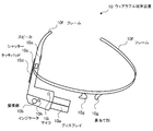
- FIG. 2 is a diagram for explaining the appearance of the wearable terminal device.
- the wearable terminal device 10 includes a display 10a, an imaging unit 10b, a shutter 10c, a touch pad 10d, a speaker 10e, a frame 10f, a nose pad unit 10g, an indicator 10h, and a microphone 10i. .
- the frame 10f is put on the ear and the nose pad portion 10g is placed on the base of the nose.
- the display 10a is attached to the frame 10f.
- the display 10a is disposed at a position where the user can visually recognize it when in use.
- the user can obtain information displayed on the display 10a in a part of the field of view.
- the display 10a may have transparency.
- the imaging unit 10b includes an image sensor such as a charge coupled device (CCD) or a complementary metal-oxide semiconductor (CMOS).
- CCD charge coupled device
- CMOS complementary metal-oxide semiconductor
- the wearable terminal device 10 can be operated using the touch pad 10d, voice commands, and blinking.
- the microphone 10i collects the command.
- a sensor mounted inside the display 10a senses blinking.
- the indicator 10h is lit or blinked when the wearable terminal device 10 is exhibiting a predetermined function (for example, an imaging function to be described later or a function for searching for a provider that provides information and services requested by the user). .
- a predetermined function for example, an imaging function to be described later or a function for searching for a provider that provides information and services requested by the user.
- a spectacle lens can be attached to the wearable terminal device 10.
- a user wearing the wearable terminal device 10 activates the main power supply of the wearable terminal device 10 and performs a predetermined operation (for example, swipes the touch pad 10d).
- a menu screen for using the functions of the wearable terminal device 10 is displayed on the side where the user's face of the display 10a is located (the back side of the display 10a in FIG. 2).
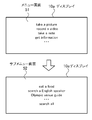
- FIG. 3 is a diagram illustrating an example of a menu screen.
- a user who takes a picture takes a video (record a video), takes a note (take a note), obtains information (get information), etc.
- the menu items that can be used are displayed.
- the menu item is selected and executed. For example, if the user wants to use the camera function of the imaging unit 10b, the imaging unit 10b takes a picture when the microphone 10i picks up the sound by pronouncing “take a picture”. Note that, during imaging using the imaging unit 10 b, for example, a shutter sound is heard from the speaker 10 e.
- the indicator 10h is turned on, and it can be seen from the surrounding people that the display 10a is turned on.
- the user can also take a picture by pressing the shutter 10c.
- the video recording time is, for example, a maximum of 10 seconds at a time.
- the user when the user wants to use the information providing function described in FIG. 1 from the menu item displayed on the menu screen 51, the user pronounces “get information” so that the microphone 10i picks up the sound and wears it.
- the terminal device 10 displays the submenu screen 52 on the display 10a.
- the microphone 10i picks up the sound by pronouncing, for example, “search a English speaker”. As shown in FIG. 1, a rectangle that can be seen through the display 10a appears around the face of the provider in a state where interpretation is possible. Then, “English OK” indicating that the interpretation service can be provided is displayed on the balloon associated with the rectangle.
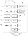
- FIG. 4 is a diagram illustrating a hardware configuration of the wearable terminal device according to the embodiment.
- the entire wearable terminal device 10 is controlled by a CPU (Central Processing Unit) 101.
- a RAM (Random Access Memory) 102 and a plurality of peripheral devices are connected to the CPU 101 via a bus 110.
- the RAM 102 is used as a main storage device of the wearable terminal device 10.
- the RAM 102 temporarily stores at least part of an OS (Operating System) program and application programs to be executed by the CPU 101.
- the RAM 102 stores various data used for processing by the CPU 101.
- the bus 110 is connected with a memory 103, a GPS chip 104, an image sensor 105, a graphic processing device 106, an input interface 107, a vibrator 108, a speaker 10e, a microphone 10i, and a communication interface 109.
- the memory 103 is a semiconductor storage device such as a flash memory.
- the memory 103 writes and reads data.
- the memory 103 stores an OS program, application programs, and various data.
- the GPS chip 104 receives radio waves emitted from GPS satellites and determines the current position (latitude and longitude). The GPS chip 104 transmits the determined current position to the CPU 101.
- the image sensor 105 captures a still image or a moving image in accordance with a command from the CPU 101.
- the captured image is stored in the RAM 102 or the memory 103 by the CPU 101.
- the graphic processor 106 is connected to a display 10a.
- the graphic processing device 105 displays an image on the screen of the display 10a in accordance with a command from the CPU 101.
- Examples of the display 10a include a liquid crystal display device.
- the input interface 107 is connected to a shutter 10c and a touch pad 10d.
- the input interface 107 transmits a signal transmitted from the shutter 10c or the touch pad 10d to the CPU 101.
- Vibrator 108 vibrates in accordance with a command from CPU 101.
- the communication interface 110 is connected to the network 50.
- the communication interface 110 transmits / receives data to / from other computers or communication devices via the network 50.
- an example of connecting directly to the network 50 has been described.
- the present invention is not limited to this, and the network 50 may be connected via another terminal device (using a tethering function). .
- FIG. 4 shows the hardware configuration of the wearable terminal device 10
- the terminal device 20 can also be realized by the same hardware configuration.
- FIG. 5 is a diagram illustrating a hardware configuration of the server apparatus according to the embodiment.
- the entire server device 30 is controlled by the CPU 301.
- a RAM 302 and a plurality of peripheral devices are connected to the CPU 301 via a bus 308.
- the RAM 302 is used as a main storage device of the server device 30.
- the RAM 302 temporarily stores at least a part of OS programs and application programs to be executed by the CPU 301.
- the RAM 302 stores various data used for processing by the CPU 301.
- the bus 308 is connected to a hard disk drive (HDD: Hard Disk Drive) 303, a graphic processing device 304, an input interface 305, a drive device 306, and a communication interface 307.
- HDD Hard Disk Drive
- the hard disk drive 303 magnetically writes and reads data to and from the built-in disk.
- the hard disk drive 303 is used as a secondary storage device of the server device 30.
- the hard disk drive 303 stores an OS program, application programs, and various data.
- a semiconductor storage device such as a flash memory can be used as the secondary storage device.
- a monitor 304 a is connected to the graphic processing device 304.
- the graphic processing device 304 displays an image on the screen of the monitor 304a in accordance with a command from the CPU 301.
- Examples of the monitor 304a include a display device using a CRT (Cathode Ray Tube), a liquid crystal display device, and the like.
- the keyboard 305a and the mouse 305b are connected to the input interface 305.
- the input interface 305 transmits a signal transmitted from the keyboard 305a or the mouse 305b to the CPU 301.
- the mouse 305b is an example of a pointing device, and other pointing devices can also be used. Examples of other pointing devices include a touch panel, a tablet, a touch pad, and a trackball.
- the drive device 306 reads data recorded on a portable recording medium such as an optical disc on which data is recorded so as to be readable by reflection of light or a USB (Universal Serial Bus) memory.
- a portable recording medium such as an optical disc on which data is recorded so as to be readable by reflection of light or a USB (Universal Serial Bus) memory.
- the drive device 306 is an optical drive device
- data recorded on the optical disc 200 is read using a laser beam or the like.
- Examples of the optical disc 200 include Blu-ray (registered trademark), DVD (Digital Versatile Disc), DVD-RAM, CD-ROM (Compact Disc Read Only Memory), CD-R (Recordable) / RW (ReWritable), and the like. .
- the communication interface 307 is connected to the network 50.
- the communication interface 307 transmits / receives data to / from other computers or communication devices via the network 50.
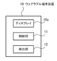
- FIG. 6 is a block diagram illustrating functions of the wearable terminal device according to the embodiment.
- the wearable terminal device 10 includes a control unit 11 and a detection unit 12.
- the control unit 11 and the detection unit 12 can be realized by the CPU 101.
- the control unit 11 controls the entire wearable terminal device 10.
- the control unit 11 has a face image recognition function. Specifically, when a face that matches the face image sent from the server device 30 is captured by the camera unit 10b and displayed on the display 10a, the control unit 11 displays the face displayed on the display 10a. The mark m1 is displayed. In addition, the control unit 11 acquires the current position of the wearable terminal device 10 from the GPS chip 104.
- the detection unit 12 performs a swipe operation, utterance, or gesture (when the user displays the menu screen 51 or the submenu screen 52 or executes a menu item displayed on the menu screen 51 or the submenu screen 52). gesture) etc. are detected.
- the detection unit 12 sends the detected information to the control unit 11.
- the control part 11 performs the process according to the detected information. For example, when a user makes an intention to provide a service to a provider, the user winks in the vicinity of the provider.
- the control unit 11 transmits an access request to the terminal device 20 possessed by the provider.
- the access request can be transmitted by using wireless communication such as Bluetooth (registered trademark).
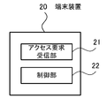
- FIG. 7 is a block diagram illustrating functions of the terminal device according to the embodiment.
- the terminal device 20 includes an access request receiving unit 21 and a control unit 22.
- the access request receiving unit 21 receives an access request issued by the wearable terminal device 10.
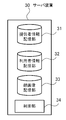
- FIG. 8 is a block diagram illustrating functions of the server device according to the embodiment.
- the server device 30 includes a provider information storage unit 31, a user information storage unit 32, a face image storage unit 33, and a control unit 34.
- the provider information storage unit 31 stores provider information.
- the provider information is information in which information related to the provider input at the time of initial registration by the provider and points obtained by the provider providing information to the user are associated with each other.
- FIG. 9 is a diagram for explaining the provider information.
- the provider information is stored as a table.
- the table T1 shown in FIG. 9 includes columns for provider terminal ID, face image ID, name, address, sex, age, occupation, provision, language, state, and points. Information arranged in the horizontal direction is associated with each other.
- the provider terminal ID column an ID unique to each terminal device assigned to each terminal device 20 possessed by the provider is set.
- face image ID column an ID for identifying the face image of the provider is set.
- the name column the name of the provider input by the provider at the time of initial registration is set.
- the address of the provider input by the provider at the time of initial registration is set in the address column.
- the sex column the sex of the provider input by the provider at the time of initial registration is set.
- the age column the age of the provider input by the provider at the time of initial registration is set.
- the column of occupation the occupation of the provider input by the provider at the initial registration is set.
- Information food guidance, venue guidance, interpretation, etc.
- the language column one or more languages that can be supported by the provider input by the provider at the time of initial registration are set.
- Information for identifying whether or not the terminal device 20 is in a standby state in which information can be provided is set in the status column. Note that the state may be set for each provided content.
- points column points (total values) obtained by providing information to the user by the provider are set.
- User information is stored in the user information storage unit 32.
- the user information is information in which information described in the presented passport when the user rents the wearable terminal device 10 is associated with a point received when the provider provides information to the user.
- FIG. 10 is a diagram illustrating user information.
- user information is stored in a table.
- the table T2 shown in FIG. 10 includes columns for user terminal ID, name, nationality, language, gender, age, passport number, and points. Information arranged in the horizontal direction is associated with each other.
- an ID unique to the wearable terminal device assigned to each wearable terminal device 10 is set. For example, when the user loses the wearable terminal device, it is possible to identify which wearable terminal device is lost by looking at the user terminal ID.
- the name of the user is set in the name column.
- the nationality of the user is set in the nationality column.
- One or more languages spoken by the user are set in the language column.
- the sex of the user is set in the gender column.
- the age of the user is set in the age column.
- a passport number possessed by the user is set.
- points possessed by the user are set.
- the points may include initial points when the wearable terminal device 10 is rented. When points are lost, points can be purchased by credit card payment.
- the face image storage unit 33 stores the face image of the provider in association with the face image ID. As described above, since the provider terminal ID and the face image ID are stored in association with each other in the table T1, the provider terminal ID and the face image are substantially associated with each other.
- control unit 34 transmits information about a provider that can provide information requested by the user to the wearable terminal device 10.
- control unit 33 manages the exchange of points between the user and the provider performed when providing information.
- FIG. 11 is a flowchart for explaining the initial setting process of the provider.
- the provider operates the terminal device 20 to access a predetermined website via the network 50, thereby FIG. 7. Download an application with the information provision function shown.
- Step S1 The terminal device 20 starts an application by the operation of the provider.
- the control unit 22 starts operating, and the process proceeds to step S2.
- Step S2 The control unit 22 determines whether it is the first activation. If it is the first activation (Yes in step S2), the process proceeds to step S3. If it is not the first activation, that is, if it is the second activation or later (No in step S2), the process proceeds to step S6.
- Step S3 The control unit 22 displays a registration screen on the monitor of the terminal device 20, and accepts input of provider information (initial registration). Moreover, the control part 22 receives the input of a provider's face image using the image pick-up element with which the terminal device 20 is provided. When the provider information and the face image are input by the provider and the transmission button is pressed, the process proceeds to step S4.
- Step S ⁇ b> 4 The control unit 22 transmits the provider information and the face image to the server device 30 in association with the provider terminal ID. Then, the process proceeds to step S5.
- the server device 30 stores the received provider information in the table T1. In addition, the server device 30 generates a unique face image ID.
- the received face image and the generated face image ID are stored in the face image storage unit 33 in association with the provider terminal ID.
- the generated face image ID is also stored in the table T1 in association with the provider terminal ID.
- Step S5 When the control unit 22 receives the notification that the provider information is stored in the table T1 from the server device 30, the control unit 22 notifies the provider using the speaker or the vibrator function. Then, the process shown in FIG. 11 is complete
- Step S ⁇ b> 6 The control unit 22 notifies the server device 30 of the standby state in association with the provider terminal ID. Then, the process shown in FIG. 11 is complete
- the provider can change the contents of the provider information stored in the server device 30 at an arbitrary timing by starting the application.
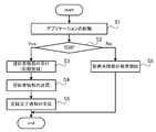
- FIG. 12 is a flowchart for explaining processing for displaying a mark around the face of the provider.
- the control unit 11 displays the menu screen 51 on the display 10a by a predetermined operation or operation of the user.
- Step S12 When the menu item “get information” is selected by the user, the control unit 11 displays the submenu screen 52 on the display 10a.
- Step S ⁇ b> 13 When any menu item is selected by the user from among the menu items displayed on the submenu screen 52, the control unit 11 transmits selection information to the server device 30.
- This selection information includes the user terminal ID of the wearable terminal device 10, the position information of the wearable terminal device 10, the menu item selected by the user, and the language used by the user. Note that the position information of the wearable terminal device 10 is acquired from the GPS chip 104 by the control unit 11.
- the control unit 34 proceeds to step S15.
- Step S15 The control unit 34 extracts position information included in the selection information. Thereafter, the process proceeds to operation S16.
- Step S16 The control unit 34 makes an inquiry to a GPS server device (not shown) to determine the provider terminal ID of the terminal device 20 located in the vicinity (for example, within 10 m) of the position information extracted in Step S15. Thereafter, the process proceeds to operation S17.
- Step S17 The control unit 34 extracts the provider terminal ID of the provider that can provide the information desired by the user using the provider terminal ID of the terminal device 20 determined in step S16 and the selection information. To do. Thereafter, the process proceeds to operation S18. This extraction process will be described in detail later.
- the control unit 34 refers to the table T1 and identifies the face image ID associated with the provider terminal ID extracted in step S17. Then, the control unit 34 refers to the face image storage unit 33 and extracts a face image associated with the specified face image ID. Then, information that associates the provider terminal ID, the extracted face image, and the menu item (hereinafter referred to as “extraction information”) is transmitted to the wearable terminal device 10.
- Step S ⁇ b> 19 Upon receiving the extraction information from the server device 30, the control unit 11 determines whether a face that matches the face image included in the received extraction information is captured by the camera unit 10 b (face authentication). . When a face that matches the face image is captured by the camera unit 10b, the control unit 11 displays the mark m1 so as to surround the face displayed on the display 10a. Then, a word indicating that the service corresponding to the menu item selected by the user can be provided is displayed on the balloon associated with the mark m1. This is the end of the description of the processing illustrated in FIG.
- step S12 After the process of step S12 is performed by the user, the processes of step S13 to step S19 may be repeatedly executed. Thereby, even when the user or the provider moves, the service provider existing in the vicinity of the user can be specified along with the movement.
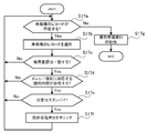
- step S17 Next, the extraction process of the provider terminal ID in step S17 will be described in detail.
- FIG. 13 is a flowchart for explaining the extraction process of the provider terminal ID.
- Step S17a The control unit 34 refers to the table T1, and among the records in the table T1 including the provider terminal ID of the terminal device 20 determined in step S16, the unprocessed records (the processes of steps S17a to S17e are performed). It is determined whether or not there is a record that has not been performed. If there is an unprocessed record (Yes in step S17a), the process proceeds to step S17b. When there is no unprocessed record (No in step S17a), the process proceeds to step S17g. [Step S ⁇ b> 17 b] The control unit 34 selects one unprocessed record. Thereafter, the process proceeds to operation S17c.
- Step S17c The control unit 34 determines whether or not the language set in the language field of the record selected in Step S17b matches the language used in the received selection information. When the language set in the language column matches the language used in the received selection information (Yes in step S17c), the process proceeds to step S17d. If the language set in the language column does not match the language used in the received selection information (No in step S17c), the process proceeds to step S17a.
- Step S17d The control unit 34 determines whether or not the provision content set in the provision column of the record selected in Step S17b matches the menu item included in the received selection information. For example, if the menu item included in the selection information is “search a English speaker”, it is determined that “interpretation” is set. If the menu item is “venue guide”, “guidance” is set, it is determined that they match.
- the provision content set in the provision column matches the menu item included in the received selection information (Yes in step S17d)
- the process proceeds to step S17e.
- the provision content set in the provision column does not match the menu item included in the received selection information (No in step S17d)
- the process proceeds to step S17a.
- Step S17e The control unit 34 determines whether or not the state set in the state column of the record selected in step S17b is standby. When the state is standby (Yes in step S17e), the process proceeds to step S17f. When the state is not standby (No in step S17e), the process proceeds to step S17a. [Step S17f] The control unit 34 checks the provider terminal ID of the record. Then, the process proceeds to step S17a. [Step S17g] The control unit 34 extracts all provider terminal IDs checked in step S17f. Then, the process shown in FIG. 13 is complete
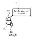
- FIG. 14 is a diagram illustrating an example of marks displayed on the display.
- the menu item displayed on the submenu screen 52 includes a menu item for searching for a seat (search a seat).
- search a seat a menu item for searching for a seat
- the wearable terminal device 10 and the server device 30 execute the process shown in FIG.
- the control unit 11 performs setting that the seat may be given, and displays the mark m1 on the display 10a so as to surround the face of the provider P6 possessing the terminal device 20 in the standby state.
- the balloon 44 associated with the rectangle displays “to offer your seat” indicating that the seat can be transferred, and the point “300 points” requested by the provider P6 to the user when the seat is transferred.
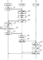
- FIG. 15 is a diagram illustrating processing when the service providing system is used for seat transfer.
- Step S21 When the detection unit 12 detects that the user has performed a predetermined operation, the control unit 11 transmits an access request to the terminal device 20 possessed by the provider P6.
- the access request can be received only by the terminal device 20 in the standby state possessed by the provider whose mark m1 is displayed on the display 10a. In other words, even if there is another terminal device 20 in the standby state, it is possessed by the provider who provides the provision contents that are not displayed on the display 10a of the user (which the user does not want).
- the terminal device 20 does not receive the access request.
- Step S22 When the access request receiving unit 21 receives the access request, the process proceeds to step S23.
- Step S23 The control unit 22 notifies the provider that the access request has been received by a vibrator function, a voice function, or the like. Thereafter, the process proceeds to operation S24.
- Step S ⁇ b> 24 By the operation of the provider, the control unit 22 transmits to the wearable terminal device 10 a point request for requesting transfer of points.
- Step S25 Upon receiving the point request, the control unit 11 proceeds to step S26.
- Step S26 The control unit 11 displays a confirmation screen on the display 10a as to whether 300 points may be transferred to the provider P6. And it waits for a user's predetermined operation
- movement for example, wink.
- Step S27 The control unit 11 transmits a point approval to the terminal device 20.
- This point approval includes the user terminal ID of the wearable terminal device 10 and points to be transferred (300 points in this specific example).
- Step S28 When the control unit 22 confirms reception of the point approval, the process proceeds to step S29. At this time, the control unit 22 may notify the provider that the point approval has been received by a vibrator function, a voice function, or the like.
- Step S ⁇ b> 29 The control unit 22 transmits a point movement request to the server device 30.
- the provider terminal ID of the terminal device 20 possessed by the provider P6 is added to the user terminal ID of the wearable terminal device 10 included in the point approval received in step S28 and the 300 points to be transferred. include.
- Step S30 Upon confirming reception of the point movement request, the control unit 34 proceeds to step S31.
- the control unit 34 refers to the table T2, and is set in the point column of the record including the user terminal ID that matches the user terminal ID included in the point movement request received in step S30. Reduce points by 300 points. Further, the control unit 34 refers to the table T2 and sets the points set in the point column of the record having the provider terminal ID that matches the provider terminal ID included in the point movement request received in step S30. Increase by 300 points. Thereafter, the process proceeds to operation S32. [Step S ⁇ b> 32] The control unit 34 transmits a point movement completion notification to the wearable terminal device 10 and the terminal device 20.
- step S28 the time of confirming that point approval was received in step S28.
- the seat may be given to the user when it is confirmed in step S32 that the point movement completion notification has been received.
- the example of moving the point when giving up the seat has been described, but whether or not to move the point may be arbitrary. For example, by displaying only “to offer your seat” in the balloon 44, it is possible to display an intention to provide a seat free of charge. This can be determined when the provider inputs the provider information.
- a healthy person may request 300 points to give up a seat, but for a pregnant woman, a disabled person, or a user with a disability, the balloon 44 may display a condition such as not requiring a point. it can.
- a condition such as not requiring a point. it can.
- the menu item displayed on the submenu screen 52 includes an Olympic venue guide (Olympic venue guide).
- the control unit 11 When the user pronounces “Olympic venue guide” and the microphone 10i picks up the sound, the control unit 11 performs a process shown in FIG.
- the mark m1 is displayed on the display 10a so as to surround the face of the provider performed using the No. 20.
- the balloon associated with the mark m1 displays “Olympic venue ⁇ guide ”indicating that the route guidance can be performed and the point“ 100 points ”requested by the provider to the user at the time of transfer.
- the user When requesting directions from this provider, the user performs a predetermined action (for example, wink) in front of the provider. Thereby, the process shown in FIG. 14 is started, and points are transferred.
- a predetermined action for example, wink
- the provider guides the user to the Olympic venue.
- the provider guides the user to the Olympic venue.
- the service providing system 1 can be used. It is possible to easily find a provider who can speak a person's language.
- the provider that provides the service desired by the user can be visually found using the wearable terminal device 10. For this reason, the possibility that the user can enjoy the service can be further increased.
- the transfer of points may be set arbitrarily.
- the service providing system 1 can be used for a commercial purpose or can be used for a non-profit purpose.
- the user can be a provider by possessing both the wearable terminal device 10 and the terminal device 20.
- the user can enjoy the service from the other party while providing the service to the other party (exchange of value and value).
- Communicating with each other is necessary to exchange services. “Communication of visual information” plays a major role in communication. “Viewpoint” and “immediateness” are important for visual information. According to the service providing system 1, a provider who provides a service desired by the user can be visually found using the wearable terminal device 10 (in contrast, a service that the user does not want is provided. The provider is not found). For this reason, the synchronism of the sender's viewpoint and empathy is transmitted directly and realistically to the receiver.
- the position of wearable terminal device 10 or terminal device 20 is specified using GPS has been described.
- the present invention is not limited to this, and for example, the location is specified using a base station of a mobile terminal device. You may make it do.
- the method for identifying a provider by recognizing a face has been described as an example.
- the method for identifying a provider is not limited to this.
- the terminal device 20 may have a part of the functions of the server device 30, or the server device 30 may have a part of the functions of the terminal device 20.
- the wearable terminal device, display method, program, and service providing system of the present invention have been described based on the illustrated embodiment.
- the present invention is not limited to this, and the configuration of each unit is the same. It can be replaced with any configuration having the above function.
- other arbitrary structures and processes may be added to the present invention.
- the present invention may be a combination of any two or more configurations (features) of the above-described embodiments.
- the above processing functions can be realized by a computer.
- a program describing the processing contents of the functions of the wearable terminal device 10 is provided.
- the program describing the processing contents can be recorded on a computer-readable recording medium.
- the computer-readable recording medium include a magnetic storage device, an optical disk, a magneto-optical recording medium, and a semiconductor memory.
- the magnetic storage device include a hard disk drive, a flexible disk (FD), and a magnetic tape.
- the optical disc include a DVD, a DVD-RAM, and a CD-ROM / RW.
- the magneto-optical recording medium include MO (Magneto-Optical disk).
- the computer that executes the program stores, for example, the program recorded on the portable recording medium or the program transferred from the server computer in its own storage device. Then, the computer reads the program from its own storage device and executes processing according to the program. The computer can also read the program directly from the portable recording medium and execute processing according to the program. In addition, each time a program is transferred from a server computer connected via a network, the computer can sequentially execute processing according to the received program.
- processing functions described above can be realized by an electronic circuit such as a DSP (Digital Signal Processor), an ASIC (Application Specific Integrated Circuit), or a PLD (Programmable Logic Device).
- DSP Digital Signal Processor
- ASIC Application Specific Integrated Circuit
- PLD Programmable Logic Device
Landscapes
- Engineering & Computer Science (AREA)
- Theoretical Computer Science (AREA)
- General Engineering & Computer Science (AREA)
- Business, Economics & Management (AREA)
- Physics & Mathematics (AREA)
- General Physics & Mathematics (AREA)
- Human Computer Interaction (AREA)
- Strategic Management (AREA)
- Computer Hardware Design (AREA)
- Development Economics (AREA)
- General Business, Economics & Management (AREA)
- Finance (AREA)
- Tourism & Hospitality (AREA)
- Marketing (AREA)
- Accounting & Taxation (AREA)
- Economics (AREA)
- Health & Medical Sciences (AREA)
- Primary Health Care (AREA)
- Human Resources & Organizations (AREA)
- Entrepreneurship & Innovation (AREA)
- General Health & Medical Sciences (AREA)
- Game Theory and Decision Science (AREA)
- User Interface Of Digital Computer (AREA)
- Management, Administration, Business Operations System, And Electronic Commerce (AREA)
- Two-Way Televisions, Distribution Of Moving Picture Or The Like (AREA)
Abstract
Priority Applications (6)
| Application Number | Priority Date | Filing Date | Title |
|---|---|---|---|
| CN201580027126.0A CN106462921A (zh) | 2014-05-13 | 2015-05-07 | 佩戴式终端装置、显示方法、程序及服务提供系统 |
| SG11201608586PA SG11201608586PA (en) | 2014-05-13 | 2015-05-07 | Wearable terminal device, display method, program, and service providing system |
| AU2015260633A AU2015260633B2 (en) | 2014-05-13 | 2015-05-07 | Wearable terminal device, display method, program, and service providing system |
| EP15792966.2A EP3144874A4 (fr) | 2014-05-13 | 2015-05-07 | Équipement terminal portable, procédé d'affichage, programme et système de fourniture de service |
| CA2941993A CA2941993C (fr) | 2014-05-13 | 2015-05-07 | Equipement terminal portable, procede d'affichage, programme et systeme de fourniture de service |
| US15/303,734 US20170038796A1 (en) | 2014-05-13 | 2015-05-07 | Wearable terminal device, display method, program, and service providing system |
Applications Claiming Priority (2)
| Application Number | Priority Date | Filing Date | Title |
|---|---|---|---|
| JP2014100038A JP6108357B2 (ja) | 2014-05-13 | 2014-05-13 | ウェアラブル端末装置、表示方法、プログラム、およびサービス提供システム |
| JP2014-100038 | 2014-05-13 |
Publications (1)
| Publication Number | Publication Date |
|---|---|
| WO2015174046A1 true WO2015174046A1 (fr) | 2015-11-19 |
Family
ID=54479597
Family Applications (1)
| Application Number | Title | Priority Date | Filing Date |
|---|---|---|---|
| PCT/JP2015/002332 WO2015174046A1 (fr) | 2014-05-13 | 2015-05-07 | Équipement terminal portable, procédé d'affichage, programme et système de fourniture de service |
Country Status (9)
| Country | Link |
|---|---|
| US (1) | US20170038796A1 (fr) |
| EP (1) | EP3144874A4 (fr) |
| JP (1) | JP6108357B2 (fr) |
| CN (1) | CN106462921A (fr) |
| AU (1) | AU2015260633B2 (fr) |
| CA (1) | CA2941993C (fr) |
| MY (1) | MY164824A (fr) |
| SG (1) | SG11201608586PA (fr) |
| WO (1) | WO2015174046A1 (fr) |
Families Citing this family (2)
| Publication number | Priority date | Publication date | Assignee | Title |
|---|---|---|---|---|
| KR102407127B1 (ko) | 2016-01-05 | 2022-06-10 | 삼성전자주식회사 | 디스플레이 시스템, 디스플레이 장치 및 그의 제어 방법 |
| JP6339285B1 (ja) * | 2017-05-09 | 2018-06-06 | ジャパンモード株式会社 | サービス提供システム |
Citations (2)
| Publication number | Priority date | Publication date | Assignee | Title |
|---|---|---|---|---|
| US20120287123A1 (en) * | 2011-05-11 | 2012-11-15 | Google Inc. | Point-of-View Object Selection |
| JP2014071812A (ja) * | 2012-10-01 | 2014-04-21 | Sony Corp | 情報処理装置、表示制御方法及びプログラム |
Family Cites Families (13)
| Publication number | Priority date | Publication date | Assignee | Title |
|---|---|---|---|---|
| US20090074258A1 (en) * | 2007-09-19 | 2009-03-19 | James Cotgreave | Systems and methods for facial recognition |
| US8711176B2 (en) * | 2008-05-22 | 2014-04-29 | Yahoo! Inc. | Virtual billboards |
| JP5589685B2 (ja) * | 2010-09-06 | 2014-09-17 | ソニー株式会社 | 情報処理装置および方法、並びにプログラム |
| WO2012083093A1 (fr) * | 2010-12-15 | 2012-06-21 | Visa International Service Association | Appareils, procédés et systèmes de plate-forme de paiement de média social |
| US9153195B2 (en) * | 2011-08-17 | 2015-10-06 | Microsoft Technology Licensing, Llc | Providing contextual personal information by a mixed reality device |
| US9285592B2 (en) * | 2011-08-18 | 2016-03-15 | Google Inc. | Wearable device with input and output structures |
| US9606992B2 (en) * | 2011-09-30 | 2017-03-28 | Microsoft Technology Licensing, Llc | Personal audio/visual apparatus providing resource management |
| US9390561B2 (en) * | 2013-04-12 | 2016-07-12 | Microsoft Technology Licensing, Llc | Personal holographic billboard |
| CN103268497B (zh) * | 2013-06-18 | 2016-03-09 | 厦门大学 | 一种人脸姿态检测方法与在人脸识别中的应用 |
| CN103777752A (zh) * | 2013-11-02 | 2014-05-07 | 上海威璞电子科技有限公司 | 基于手臂肌肉电流检测和运动传感器的手势识别设备 |
| US10078863B2 (en) * | 2013-12-26 | 2018-09-18 | Paypal, Inc. | Systems and methods for augmented reality payments |
| US20150198446A1 (en) * | 2014-01-15 | 2015-07-16 | Mastercard International Incorporated | Atm and card acceptance locations using augmented reality method and apparatus |
| US9588342B2 (en) * | 2014-04-11 | 2017-03-07 | Bank Of America Corporation | Customer recognition through use of an optical head-mounted display in a wearable computing device |
-
2014
- 2014-05-13 JP JP2014100038A patent/JP6108357B2/ja active Active
-
2015
- 2015-05-07 SG SG11201608586PA patent/SG11201608586PA/en unknown
- 2015-05-07 CN CN201580027126.0A patent/CN106462921A/zh active Pending
- 2015-05-07 WO PCT/JP2015/002332 patent/WO2015174046A1/fr active Application Filing
- 2015-05-07 CA CA2941993A patent/CA2941993C/fr active Active
- 2015-05-07 MY MYPI2016703921A patent/MY164824A/en unknown
- 2015-05-07 EP EP15792966.2A patent/EP3144874A4/fr not_active Withdrawn
- 2015-05-07 AU AU2015260633A patent/AU2015260633B2/en not_active Ceased
- 2015-05-07 US US15/303,734 patent/US20170038796A1/en not_active Abandoned
Patent Citations (2)
| Publication number | Priority date | Publication date | Assignee | Title |
|---|---|---|---|---|
| US20120287123A1 (en) * | 2011-05-11 | 2012-11-15 | Google Inc. | Point-of-View Object Selection |
| JP2014071812A (ja) * | 2012-10-01 | 2014-04-21 | Sony Corp | 情報処理装置、表示制御方法及びプログラム |
Non-Patent Citations (4)
| Title |
|---|
| MATT MCGEE: "The Google Glass Privacy Debate: What's Real & What's Overblown Hype", XP055360694, Retrieved from the Internet <URL:http://web.archive.org/web/20130707111458/http://marketingland.com/the-google-glass-privacy-debate-whats-real-whats-overblown-hype-50745> * |
| See also references of EP3144874A4 * |
| Y OICHI YAMASHITA: "Google Glass Taikenroku 25-fun de Wakaru Glass no Tsukaikata (User Interface Hen", 10 February 2014 (2014-02-10), XP055394892, Retrieved from the Internet <URL:http://web.archive.org/web/20140311093123> [retrieved on 20150611] * |
| Y OICHI YAMASHITA: "Google Glass Taikenroku 3 Glass wa Honto ni Privacy o Shingai suru noka?", 27 March 2014 (2014-03-27), XP055394887, Retrieved from the Internet <URL:http://web.archive.org/web/20140405201926/http://news.mynavi.jp/column/gglass/003> [retrieved on 20150611] * |
Also Published As
| Publication number | Publication date |
|---|---|
| AU2015260633A1 (en) | 2016-11-24 |
| SG11201608586PA (en) | 2016-11-29 |
| EP3144874A4 (fr) | 2017-12-06 |
| US20170038796A1 (en) | 2017-02-09 |
| CN106462921A (zh) | 2017-02-22 |
| CA2941993C (fr) | 2018-11-06 |
| JP2015219536A (ja) | 2015-12-07 |
| CA2941993A1 (fr) | 2015-11-19 |
| JP6108357B2 (ja) | 2017-04-05 |
| MY164824A (en) | 2018-01-30 |
| EP3144874A1 (fr) | 2017-03-22 |
| AU2015260633B2 (en) | 2018-06-28 |
Similar Documents
| Publication | Publication Date | Title |
|---|---|---|
| US11341534B2 (en) | Server-based intelligent and personalized advertisement with augmented reality enhancement | |
| US11363327B2 (en) | Method for displaying virtual item, terminal and storage medium | |
| US10990613B2 (en) | Information processing apparatus and information processing method | |
| CN103748609B (zh) | 用于传送来自不同设备的媒体回放的方法 | |
| CN114270257A (zh) | 带有激光投影系统的可穿戴多媒体设备和云计算平台 | |
| KR102238330B1 (ko) | 디스플레이 장치 및 그의 동작 방법 | |
| CN110377195B (zh) | 展示交互功能的方法和装置 | |
| JP6339285B1 (ja) | サービス提供システム | |
| CN113473164A (zh) | 直播数据处理方法、装置、计算机设备及介质 | |
| US11606401B2 (en) | Method for processing live streaming data and server | |
| EP3132397B1 (fr) | Système pour fournir un service de journal de vie et procédé de fourniture du service | |
| CN112115282A (zh) | 基于搜索的问答方法、装置、设备及存储介质 | |
| CN113891106A (zh) | 基于直播间的资源展示方法、装置、终端及存储介质 | |
| JP6108357B2 (ja) | ウェアラブル端末装置、表示方法、プログラム、およびサービス提供システム | |
| JP6403286B2 (ja) | 情報管理方法及び情報管理装置 | |
| WO2016147744A1 (fr) | Dispositif de traitement d'informations, procédé de traitement d'informations et programme d'ordinateur | |
| US11663924B2 (en) | Method for live streaming | |
| CN113377271A (zh) | 文本获取方法、装置、计算机设备及介质 | |
| CN113841121A (zh) | 用于提供应用内消息收发的系统和方法 | |
| KR20160001028A (ko) | 음향 효과를 이용한 푸쉬 투 토크 서비스 제공 방법 | |
| JP6995224B1 (ja) | 仮想旅行提供方法 | |
| JP7192749B2 (ja) | サーバ、情報処理システム、プログラム及び制御方法 | |
| WO2024063867A1 (fr) | Fourniture en sortie et synchronisation de contenu multimédia multi-sources | |
| CN111242338A (zh) | 卡片获取方法、装置、终端及存储介质 | |
| CN116257159A (zh) | 多媒体内容的分享方法、装置、设备、介质及程序产品 |
Legal Events
| Date | Code | Title | Description |
|---|---|---|---|
| 121 | Ep: the epo has been informed by wipo that ep was designated in this application |
Ref document number: 15792966 Country of ref document: EP Kind code of ref document: A1 |
|
| ENP | Entry into the national phase |
Ref document number: 2941993 Country of ref document: CA |
|
| WWE | Wipo information: entry into national phase |
Ref document number: 15303734 Country of ref document: US |
|
| REEP | Request for entry into the european phase |
Ref document number: 2015792966 Country of ref document: EP |
|
| WWE | Wipo information: entry into national phase |
Ref document number: 2015792966 Country of ref document: EP |
|
| NENP | Non-entry into the national phase |
Ref country code: DE |
|
| ENP | Entry into the national phase |
Ref document number: 2015260633 Country of ref document: AU Date of ref document: 20150507 Kind code of ref document: A |