WO2015170475A1 - 通信装置、通信システム、通信方法および通信用プログラムが記憶された記憶媒体 - Google Patents
通信装置、通信システム、通信方法および通信用プログラムが記憶された記憶媒体 Download PDFInfo
- Publication number
- WO2015170475A1 WO2015170475A1 PCT/JP2015/002320 JP2015002320W WO2015170475A1 WO 2015170475 A1 WO2015170475 A1 WO 2015170475A1 JP 2015002320 W JP2015002320 W JP 2015002320W WO 2015170475 A1 WO2015170475 A1 WO 2015170475A1
- Authority
- WO
- WIPO (PCT)
- Prior art keywords
- frame
- output
- line
- unit
- control frame
- Prior art date
Links
Images


Classifications
-
- H—ELECTRICITY
- H04—ELECTRIC COMMUNICATION TECHNIQUE
- H04L—TRANSMISSION OF DIGITAL INFORMATION, e.g. TELEGRAPHIC COMMUNICATION
- H04L43/00—Arrangements for monitoring or testing data switching networks
- H04L43/08—Monitoring or testing based on specific metrics, e.g. QoS, energy consumption or environmental parameters
- H04L43/0876—Network utilisation, e.g. volume of load or congestion level
- H04L43/0894—Packet rate
-
- H—ELECTRICITY
- H04—ELECTRIC COMMUNICATION TECHNIQUE
- H04L—TRANSMISSION OF DIGITAL INFORMATION, e.g. TELEGRAPHIC COMMUNICATION
- H04L45/00—Routing or path finding of packets in data switching networks
- H04L45/12—Shortest path evaluation
- H04L45/125—Shortest path evaluation based on throughput or bandwidth
-
- H—ELECTRICITY
- H04—ELECTRIC COMMUNICATION TECHNIQUE
- H04L—TRANSMISSION OF DIGITAL INFORMATION, e.g. TELEGRAPHIC COMMUNICATION
- H04L45/00—Routing or path finding of packets in data switching networks
- H04L45/24—Multipath
- H04L45/245—Link aggregation, e.g. trunking
-
- H—ELECTRICITY
- H04—ELECTRIC COMMUNICATION TECHNIQUE
- H04L—TRANSMISSION OF DIGITAL INFORMATION, e.g. TELEGRAPHIC COMMUNICATION
- H04L47/00—Traffic control in data switching networks
- H04L47/10—Flow control; Congestion control
- H04L47/25—Flow control; Congestion control with rate being modified by the source upon detecting a change of network conditions
-
- H—ELECTRICITY
- H04—ELECTRIC COMMUNICATION TECHNIQUE
- H04L—TRANSMISSION OF DIGITAL INFORMATION, e.g. TELEGRAPHIC COMMUNICATION
- H04L47/00—Traffic control in data switching networks
- H04L47/10—Flow control; Congestion control
- H04L47/28—Flow control; Congestion control in relation to timing considerations
-
- H—ELECTRICITY
- H04—ELECTRIC COMMUNICATION TECHNIQUE
- H04L—TRANSMISSION OF DIGITAL INFORMATION, e.g. TELEGRAPHIC COMMUNICATION
- H04L47/00—Traffic control in data switching networks
- H04L47/10—Flow control; Congestion control
- H04L47/30—Flow control; Congestion control in combination with information about buffer occupancy at either end or at transit nodes
-
- H—ELECTRICITY
- H04—ELECTRIC COMMUNICATION TECHNIQUE
- H04L—TRANSMISSION OF DIGITAL INFORMATION, e.g. TELEGRAPHIC COMMUNICATION
- H04L47/00—Traffic control in data switching networks
- H04L47/10—Flow control; Congestion control
- H04L47/36—Flow control; Congestion control by determining packet size, e.g. maximum transfer unit [MTU]
Definitions
- the present invention relates to a communication apparatus, a communication system, a communication method, and a storage medium storing a communication program that perform data transfer by aggregating a plurality of communication lines.
- a link aggregation standardized by IEEE (The Institute of Electrical and Electronics Engineers, Inc.) 802.3ad is a technology for increasing communication bandwidth using multiple lines.
- frames are distributed to a plurality of lines based on MAC (Media Access Control Address) addresses, IP (Internet Protocol) addresses, and the like.
- MAC Media Access Control Address
- IP Internet Protocol
- Patent Document 1 describes a method of performing retransmission processing when data packets are transmitted in parallel using a plurality of wireless channels and transmitted normally and are not normally transmitted.
- a plurality of data packets whose transmission times are equal to each other in several units that can be transmitted in parallel are generated from the data frames stored in the transmission buffer and are continuously transmitted in several units that can be transmitted in parallel. Send in parallel.
- dummy bits are added to the data packet with a short required transmission time during parallel retransmission, so that the required transmission times are aligned with other data packets.
- the present invention stores a communication device, a communication system, a communication method, and a communication program that can suppress a deviation in the amount of data transferred by each line when data transfer is performed using a plurality of communication lines.
- An object is to provide a storage medium.
- a communication apparatus is a communication apparatus that performs data transfer using a plurality of lines, and divides the divided frames in accordance with a dividing unit that divides an input frame and an output band of the plurality of lines.
- a distribution unit, and a transmission unit that transmits the distributed frame wherein the distribution unit is configured to output a data amount that can be output in a unit time for each line as an output band at a predetermined period on the line.
- the frame is allocated to the line with the smallest remaining output weight indicating the ratio of the remaining data amount that can be output to the transmission unit, and the transmission means transmits a dummy frame corresponding to the remaining data amount when a predetermined period elapses. .
- the communication system includes a plurality of communication apparatuses that perform data transfer using a plurality of lines, and the communication apparatus is divided according to a dividing unit that divides an input frame and an output band of the plurality of lines.
- Distribution means for distributing the allocated frames, and transmission means for transmitting the allocated frames.
- the distribution means uses the line to output the amount of data that can be output per unit time set for each line as an output band.
- the frame is allocated to the line with the smallest remaining output weight indicating the ratio of the remaining amount of data that can be output every predetermined period, and the transmission means transmits a dummy frame corresponding to the remaining amount of data when the predetermined period elapses. It is characterized by.
- the communication method according to the present invention is a communication method in the case where data transfer is performed using a plurality of lines, and the amount of data that can be output per unit time set for each line as an output band by dividing an input frame
- the divided frames are allocated to the line with the smallest remaining output weight indicating the ratio of the remaining amount of data that can be output for each predetermined cycle on the line, and the remaining frames when the predetermined period elapses.
- a dummy frame corresponding to the amount of data is transmitted.
- a storage medium storing a communication program according to the present invention is a storage medium storing a communication program applied to a computer that performs data transfer using a plurality of lines.
- Each line is output as an output band in the distribution process by executing the division process for dividing, the distribution process for distributing the divided frames according to the output bandwidth of a plurality of lines, and the transmission process for transmitting the distributed frames.
- the frame is allocated to the line with the smallest remaining output weight that indicates the ratio of the remaining amount of data that can be output in a given period to the amount of data that can be output per unit time set to
- a communication program for transmitting a dummy frame corresponding to the remaining data amount when a predetermined period has elapsed is stored.
- FIG. 1 is a block diagram illustrating an embodiment of a communication system according to the present invention. It is explanatory drawing which shows the example of a data frame transmission process. It is explanatory drawing which shows the example of a data frame reception process. It is explanatory drawing which shows the example of the data frame before a division
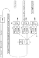
- FIG. 1 is a block diagram showing an embodiment of a communication system according to the present invention.
- the communication system of this embodiment includes two communication devices 1 and a communication device 15.
- the communication device 1 and the communication device 15 are devices having the same function, and include a reception unit 2 and a transmission unit 3. Note that the communication device 1 and the communication device 15 may include functions different from each other in addition to the reception unit 2 and the transmission unit 3.
- the communication device 1 and the communication device 15 are connected to each other via a plurality of lines 1, lines 2,.
- the communication device 1 and the communication device 15 are paired, and communication is performed between the two communication devices.
- the communication apparatus 1 and the communication apparatus 15 may be directly connected, and may be connected via another apparatus. Even when the connection is made via another device, the frame destination of the communication device 1 is the communication device 15. In the present embodiment, it is assumed that a frame transmitted by a device other than the communication device 1 is not input to the communication device 15.
- the transmission unit 3 includes a division unit 4, a bandwidth management unit 5, an allocation unit 6, a plurality of control frame generation units 7-1 to 7-n, storage units 8-1 to 8-n, and arbitration units 9-1 to 9 -N.
- a control frame generation unit 7, a storage unit 8, and an arbitration unit 9 are provided for each line (port) to be connected.
- the dividing unit 4 divides the input frame and inputs it to the distribution unit 6.
- the method by which the dividing unit 4 divides the frame is arbitrary, and the dividing unit 4 may divide the frame using a widely known method.
- the bandwidth management unit 5 manages the output bandwidth of each line.
- the distribution unit 6 distributes the divided frames in accordance with the output bandwidth of each line and inputs them to the storage unit 8. The contents of the output band managed by the band management unit 5 and the method by which the distribution unit 6 distributes the divided frames will be described later.
- the control frame generation unit 7 generates a control frame to be transmitted to another communication device. Further, the control frame generation unit 7 generates a dummy frame to be transmitted when there are few data frames to be transmitted with respect to the output band of each line managed by the band management unit 5. Details of the control frame and the dummy frame will be described later.
- the storage unit 8 temporarily holds the frame input from the distribution unit 6.
- the arbitration unit 9 sequentially transmits the frames input to the storage unit 8 via the connected line.
- the division unit 4, the bandwidth management unit 5, the distribution unit 6, the control frame generation unit 7, and the arbitration unit 9 are realized by a CPU (Central Processing Unit) of a computer that operates according to a program (communication program).
- the program is stored in a storage unit (not shown) of the communication device 1, and the CPU reads the program, and according to the program, the dividing unit 4, the bandwidth management unit 5, the distribution unit 6, and the control frame generation unit 7. And it may operate as the arbitration unit 9.
- the dividing unit 4, the bandwidth managing unit 5, the allocating unit 6, the control frame generating unit 7, and the arbitrating unit 9 may each be realized by dedicated hardware.
- the storage unit 8 is realized by, for example, a memory.
- FIG. 2 is an explanatory diagram illustrating an example of a data frame transmission process performed by the transmission unit 3.
- the dividing unit 4 divides each frame, assigns a sequence number, a head flag and an end flag to the divided frames, and assigns the distributing unit 6 To enter.
- the head flag is a flag for identifying whether the data is the head data of the divided frame
- the tail flag is a flag for identifying whether the data is the tail data of the divided frame.
- sequence number of frame 1a is n
- sequence number of frame 1b is n + 1
- sequence number of frame 1c is n + 2
- sequence number of frame 2 is n + 3
- sequence number of frame 3a is n + 4
- sequence number of frame 3b Becomes n + 5.
- the distribution unit 6 transmits a frame to the storage unit 8 (8-1, 8-2, 8-3) of each line according to the output band of each line managed by the band management unit 5.
- the output band of the line 2 is the largest and the output band of the line 1 is the smallest.
- a storage unit 8 provided for each line stores received frames.
- the arbitration unit 9 (9-1, 9-2, 9-3) reads out the frame stored in the storage unit 8 and transmits it to each connected line.
- the receiving unit 2 includes a plurality of filter units 10-1 to 10-n, control frame processing units 11-1 to 11-n, storage units 12-1 to 12-n, a reading unit 13, and a combining unit 14.
- a filter unit 10 a control frame processing unit 11, and a storage unit 12, respectively.
- the filter unit 10, the control frame processing unit 11, and the storage unit 12 are provided for each line (port) to be connected.
- the filter unit 10 receives a frame transmitted from another device and inputs the frame to the control frame processing unit 11 and the storage unit 12.
- the control frame processing unit 11 processes the received control frame.
- the storage unit 12 temporarily holds the frame input from the filter unit 10.
- the reading unit 13 reads the frame held in each storage unit 12 and inputs the frame to the combining unit 14.
- the combining unit 14 combines the frames input from the reading unit 13 and transmits them to another device.
- the filter unit 10, the control frame processing unit 11, the reading unit 13, and the combining unit 14 are realized by a CPU of a computer that operates according to a program (communication program).
- the program is stored in a storage unit (not shown) of the communication apparatus 1, and the CPU reads the program and operates as the filter unit 10, the control frame processing unit 11, the reading unit 13, and the combining unit 14 according to the program. May be.
- each of the filter unit 10, the control frame processing unit 11, the reading unit 13, and the combining unit 14 may be realized by dedicated hardware.
- the storage unit 12 is realized by, for example, a memory.
- FIG. 3 is an explanatory diagram illustrating an example of a data frame reception process performed by the reception unit 2.
- a frame 1a, a frame 1b, a frame 1c, a frame 2, a frame 3a, and a frame 3b illustrated in FIG. 3 are frames transmitted by each arbitration unit 9 illustrated in FIG.
- the filter unit 10 (10-1, 10-2, 10-3) inputs the transmitted data frame to the storage unit 12 (12-1, 12-2, 12-3).
- the reading unit 13 reads the data frames stored in the storage unit 12 in the order of sequence numbers regardless of the arrival order, and inputs the data frames to the combining unit 14.
- the reading unit 13 reads a frame obtained by adding 1 to the sequence number of the previous frame in order from the frame 1a having the smallest sequence number as the next frame.
- the combining unit 14 recognizes a frame from a frame having a head flag of 1 to a frame having a tail flag of 1 as a frame before division. Then, the combining unit 14 deletes the sequence number, the head flag, and the tail flag from the divided frames, combines them, restores the frames before the division, and transmits them.
- the control frame is used for line connection confirmation and dynamic output bandwidth control.
- the control frame is generated by the control frame generation unit 7 (7-1, 7-2,..., 7-n) of the transmission unit 3 in FIG.
- the arbitration unit 9 (9-1, 9-2,..., 9-n) arbitrates between the data frame and the control frame, and the control frame is output to the line.
- the control frame processing unit 11 analyzes the contents of the control frame, and uses the analyzed contents to generate output bandwidth control and a control frame for transmission.
- the dummy frame is a frame that is inserted for an empty band when the output data frame is smaller than the set output band. This dummy frame is also used for dynamic output bandwidth control described later.
- the bandwidth management unit 5 controls the control frame generation unit 7 (7-1, 7-2,..., 7 ⁇ corresponding to each line when the output data frame is smaller than the output bandwidth to be managed. Notify n).
- the control frame generation unit 7 Upon receiving the notification, the control frame generation unit 7 generates a dummy frame so that the output frame is an output band managed by the band management unit 5, and outputs the dummy frame to the arbitration unit 9.
- the arbitration unit 9 transmits a dummy frame for which output arbitration with the data frame has been performed.
- the control frame processing unit 11 (11-1, 11-2,..., 11-n). Then, the control frame processing unit 11 discards the input dummy frame.
- FIG. 4 is an explanatory diagram illustrating an example of a data frame before division.
- the pre-division data frame 21 illustrated in FIG. 4 includes a header 22 and a payload 23 necessary to make the network transparent.
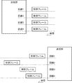
- FIG. 5 is an explanatory diagram showing an example of the divided data frame.
- the post-division data frames 24-a to 24-c are generated from the pre-division data frame 21 illustrated in FIG. In the example shown in FIG. 5, the pre-division data frame is divided into three frames.
- the division unit 4 divides the pre-division data frame 21 into pre-division data frame division data 31. Further, the dividing unit 4 adds a header 25, a sequence number 26, a head flag 27, a tail flag 28, a control flag 29, and a dummy flag 30 to each divided data to generate a divided data frame.
- the header 25 is a header necessary for the data frame to pass through the network, and is newly added separately from the header 22 of the data frame before division.
- the sequence number 26 is used by the reading unit 13 of the receiving unit 2 to rearrange the divided data frames.
- the value of the sequence number 26 is a value obtained by adding 1 to the sequence number of the immediately preceding divided data frame.
- the head flag 27 is a flag indicating the head of the pre-division data frame. Among the divided data frames illustrated in FIG. 5, only the divided data frame 24-a has the leading flag 27 set to 1, and the divided data frame 24-b and the divided data frame 24-c have the leading flag 27 set to 0. Set to
- the end flag 28 is a flag indicating the end of the pre-division data frame.
- the tail flag 28 is set to 1 only in the divided data frame 24-c, and the tail flag 28 of the divided data frame 24-a and the divided data frame 24-b is 0.
- the start flag 27 and the end flag 28 are used by the combining unit 14 of the receiving unit 2 to assemble a frame.
- the control flag 29 is a flag indicating that the frame is a control frame.
- the dummy flag 30 is a flag indicating that the frame is a dummy frame. In the case of the divided data frame illustrated in FIG. 5, the control flag 29 and the dummy flag 30 are set to 0.
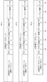
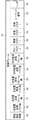
- FIG. 6 is an explanatory diagram illustrating an example of a control frame format.
- the control frame 32 includes a header 25, a sequence number 26, a head flag 27, a tail flag 28, a control flag 29, and a dummy flag 30 in the same manner as the divided data frame illustrated in FIG.
- the value of the sequence number 26 of the control frame is a value obtained by adding 1 to the sequence number of the previous control frame 32. Further, 1 is fixedly set in the head flag 27 and the tail flag 28. Further, since the control flag 29 is a field indicating a control frame, 1 is set.
- the dummy flag 30 is set to 0 because it is a field indicating a dummy frame.
- the filter unit 10 of the receiving unit 2 determines that a frame in which 1 is set in the control flag 29 is a control frame, and outputs it to the control frame processing unit 11. That is, the filter unit 10 uses whether or not 1 is set in the control flag 29 as a control frame condition.
- control frame 32 includes, in addition to the information included in the divided data frame, the counter device transmission frame number 33, the counter device transmission byte number 34, the device reception frame number 35, and the device reception byte number. 36, own device transmission frame number 37, own device transmission byte number 38, and delay measurement information 39 are included.
- the counter device transmission frame number 33 indicates the number of frames transmitted from the opposite communication device.
- the counter device transmission byte count 34 indicates the number of bytes of the frame transmitted from the counter communication device.
- the own device reception frame number 35 indicates the number of frames received from the opposite communication device.
- the own device received byte number 36 indicates the number of bytes of the frame received from the opposite communication device.
- the own device transmission frame number 37 represents the number of frames transmitted by the own communication device.
- the own device transmission byte number 38 represents the number of bytes of the frame transmitted by the own communication device.
- the delay measurement information 39 represents a delay time measured when a frame transmission is transmitted. A method of using each field included in the control frame will be described in the description of the output band adjustment function described later.
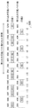
- FIG. 7 is an explanatory diagram showing an example of a dummy frame format. Similar to the divided data frame 24 illustrated in FIG. 5 and the control frame 32 illustrated in FIG. 6, the dummy frame 40 includes a header 25, a sequence number 26, a head flag 27, a tail flag 28, a control flag 29, and a dummy flag. 30 is included.
- the value of the sequence number 26 of the dummy frame is fixedly set to 0, and the values of the start flag 27 and the end flag 28 are fixedly set to 1.
- the control flag 29 is set to 0, and the dummy flag 30 is set to 1.
- the filter unit 10 of the receiving unit 2 determines that a frame for which 1 is set in the dummy flag 30 is a dummy frame and outputs the frame to the control frame processing unit 11. That is, the filter unit 10 uses whether or not 1 is set in the dummy flag 30 as a dummy frame condition.
- the bandwidth management unit 5 manages the amount of data that can be output per unit time set for each line as an output bandwidth and the remaining amount of data that can be output for each predetermined period on that line. Specifically, the bandwidth management unit 5 holds the number of bytes that can be output per unit time as the amount of data that can be output per unit time, and the remaining number of bytes that can be output as the remaining amount of data that can be output every predetermined period. For each line. This unit time is fixedly set in an arbitrary unit.
- the distribution unit 6 notifies the bandwidth management unit 5 of the number of bytes of the output divided data frame each time the divided data frame is output to the line.
- the bandwidth management unit 5 subtracts the notified number of bytes of the divided data frame from the number of remaining outputtable bytes.
- the bandwidth management unit 5 sets the amount of data that can be output (number of bytes that can be output) to the amount of remaining data that can be output (number of bytes that can be output) for each predetermined period. That is, the bandwidth management unit 5 performs a process of resetting the remaining number of outputtable bytes to return to the number of outputtable bytes at every predetermined period. Specifically, the bandwidth management unit 5 loads the number of bytes that can be output per unit time to the number of bytes that can be output for each reset period.
- the distribution unit 6 calculates a value indicating the ratio of the remaining data amount that can be output to the data amount that can be output.
- the value calculated in this way is referred to as remaining output weight.
- the allocating unit 6 may calculate the remaining output weight using Equation 1 illustrated below.
- Remaining output weight number of bytes that can be output / number of bytes that can be output per unit time (Equation 1)
- the distribution unit 6 distributes the frame to the line having the largest remaining output weight. That is, the line on which the divided data frame is output is the line with the largest remaining output weight.
- FIG. 8 is an explanatory diagram showing an example of processing for distributing frames.
- frames are distributed using two lines (line 1 and line 2).
- line 1 and line 2 the line 1 illustrated in FIG. 8 has 1200 outputable bytes per unit time
- the line 2 has 600 outputable bytes per unit time.
- frames are denoted by # and 15 frames # 1 to # 15 are transmitted. Note that the number of bytes in the frame is all 200.
- the number of bytes that can be output per unit time is set as the number of bytes that can be output at time t1, the number of bytes that can be output on line 1 is 1200, and the number of bytes that can be output on line 2 is 600.
- the distribution unit 6 calculates the remaining output weight as the distribution process. At time t1, the remaining output weights of the line 1 and the line 2 have the same value, so the allocating unit 6 distributes the frame # 1 to the line 1 having a smaller number.
- the distribution unit 6 subtracts 200 from the remaining number of bytes that can be output from the line 1 and calculates 1000.
- the allocating unit 6 calculates the remaining output weight of the line 1 as about 0.83 and calculates the remaining output weight of the line 2 as 1.00. Therefore, the distribution unit 6 distributes the frame # 2 to the line 2 having a larger remaining output weight. Then, the distribution unit 6 calculates 400 by subtracting 200 the remaining number of bytes that can be output from the line 2.
- the allocating unit 6 calculates the remaining output weight of the line 1 as about 0.83 and calculates the remaining output weight of the line 2 as about 0.67. Therefore, the distribution unit 6 distributes the frame # 3 to the line 1 having a larger remaining output weight. Thereafter, the same processing is repeated.
- the bandwidth management unit 5 sets the number of bytes that can be output per unit time as the number of bytes that can be output. That is, the remaining number of bytes that can be output from line 1 is set to 1200, and the number of bytes that can be output from line 2 is set to 600.
- the bandwidth management unit 5 sets the remaining number of outputtable bytes to the control frame generation unit 7. Notify The control frame generation unit 7 generates dummy frames for the number of remaining outputtable bytes and outputs the dummy frames to the arbitration unit 9.
- the allocating unit 6 compares the remaining output weights between the lines and performs the distribution process, the line 1 and the line 2 correspond to the number of bytes that can be output per unit time. Frames are output evenly.
- the allocating unit 6 does not output the divided data frame to the line having the largest remaining output possible number of bytes but to the line having the largest remaining output weight. Therefore, there is no time bias, and frames can be output equally to each line.
- FIG. 9 is an explanatory diagram showing an operation example when a frame is output to a line having the largest number of remaining outputtable bytes.
- the number of bytes that can be output from line 1 is equal to or greater than the number of bytes that can be output from line 2. Therefore, during this period, the frames are not distributed evenly, and are distributed only to the line 1. Thereafter, after the remaining number of bytes that can be output on the line 1 falls below the number of bytes that can be output on the line 2, the frames are alternately allocated to the lines 1 and 2.
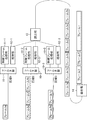
- FIG. 10 is an explanatory diagram illustrating an example of a method of adjusting the output band.
- the solid arrow illustrated in FIG. 10 indicates the flow of the frame, and the dotted arrow indicates the flow of the control frame.
- the output band adjustment function includes a function to widen the output band and a function to narrow the output band.
- the state in which the function for expanding the output band is executed is referred to as an output band increase mode, and the state in which the function for narrowing the output band is executed is referred to as an output band reduction mode.
- the output band reduction mode is set in the initial state, and processing for narrowing the output band is performed.
- the bandwidth management unit 5 sets the output bandwidth of the target line to be narrow.
- the new output band is calculated based on the number of frames and the number of bytes received from the communication device 15.
- the arbitrating unit 9 of the communication device 1 counts the number of frames and the number of bytes of the transmitted divided data frame and dummy frame.
- the counted value is held, for example, in a memory (not shown) included in the arbitration unit 9.
- the arbitration unit 9 does not count the number of frames and the number of bytes of the control frame.
- the control frame generation unit 7 generates a control frame at a predetermined timing and inputs it to the arbitration unit 9.
- the arbitrating unit 9 sets the number of frames to be held in the own device transmission frame number 37 of the input control frame 32 and sets the number of bytes to be held in the own device transmission byte number 38 of the control frame 32. Then, the arbitration unit 9 transmits the control frame 32 in which the number of frames and the number of bytes are set to the communication device 15. When the control frame 32 is transmitted, the arbitration unit 9 resets the number of frames and bytes to be held to zero.
- the filter unit 10 of the communication device 15 When receiving the divided data frame and the dummy frame, the filter unit 10 of the communication device 15 counts the number of frames and the number of bytes of the received frame. The counted value is held in, for example, a memory (not shown) included in the filter unit 10. The filter unit 10 does not count the number of control frames and the number of bytes.
- the filter unit 10 When receiving the control frame, the filter unit 10 transmits the received control frame to the control frame processing unit 11. At the same time, the filter unit 10 notifies the control frame processing unit 11 of the counted number of frames and bytes.
- the control frame processing unit 11 notifies the control frame generation unit 7 of the own communication device 15 of the own device transmission frame number 37 included in the control frame 32 as the counter device transmission frame number. Further, the control frame processing unit 11 notifies the control frame generation unit 7 of the own communication device 15 of the own device transmission byte number 38 included in the control frame 32 as the counter device transmission byte number. Further, the control frame processing unit 11 notifies the control frame generation unit 7 of the own communication device 15 of the number of frames notified from the filter unit 10 of the own communication device 15 as the number of received frames of the own device. Further, the control frame processing unit 11 notifies the control frame generation unit 7 of the own communication device 15 of the number of bytes notified from the filter unit 10 of the own communication device 15 as the received device byte count.
- the control frame generation unit 7 of the communication device 15 sets the number of opposite device transmission frames notified from the control frame processing unit 11 as the number of opposite device transmission frames 33 of the control frame 32. Further, the control frame generation unit 7 of the communication device 15 sets the counter device transmission byte number notified from the control frame processing unit 11 in the counter device transmission byte number 34 of the control frame 32.
- control frame generation unit 7 of the communication device 15 sets the number of received frames received from the control frame processing unit 11 in the number 35 of received frames of the control frame 32.
- control frame generation unit 7 of the communication device 15 sets the number of received bytes received from the control frame processing unit 11 as the number of received bytes 36 of the control frame 32. Then, the arbitrating unit 9 of the communication device 15 transmits the control frame 32 in which each information is set to the communication device 1.
- the control frame processing unit 11 compares the counter device transmission frame number 33 included in the control frame 32 with the own device reception frame number 35. When the counter device transmission frame number 33 is larger than the own device reception frame number 35, the control frame processing unit 11 of the communication device 1 determines that the output band is to be narrowed, calculates a newly set output region, This is notified to the bandwidth management unit 5 of the communication device 1.
- the new output band may be calculated using, for example, Expression 2 illustrated below.
- New output bandwidth Number of received bytes of own device 36 ⁇ Control frame transmission interval ... (Formula 2)
- the bandwidth management unit 5 of this embodiment manages the output bandwidth based on the number of bytes that can be output per unit time. Therefore, the bandwidth management unit 5 may calculate the number of bytes that can be output per unit time using Equation 3 illustrated below, and update the output bandwidth based on the calculated value.
- the arbitration unit 9 transmits the control frame 32 including the transmission data amount transmitted from each line to the communication device 15, and the filter unit 10 controls the control frame by the arbitration unit 9.
- the control frame 32 transmitted from the communication device 15 is received in response to the transmission.
- the received control frame 32 includes the amount of received data received by the communication device 15, and when the received data amount is smaller than the transmitted data amount, the bandwidth management unit 5 transmits the line that transmitted the control frame. Set the output bandwidth of to narrow. By narrowing the output band in this way, it is possible to further suppress the deviation of the data amount of each line.
- the control frame generation unit 7 of the communication device 1 temporarily inserts many dummy frames, and the control frame processing unit 11 measures the delay time of the frame before and after that.
- the control frame processing unit 11 determines that a delay has occurred due to the communication band exceeding the physical band in the network between the communication apparatus 1 and the communication apparatus 15, and widens the output band. Judge that it is not possible.
- the control frame processing unit 11 determines that the output band can be expanded.
- the bandwidth management unit 5 of the communication device 1 notifies the control frame generation unit 7 of the communication device 1 of the remaining number of bytes that can be output.
- the control frame generation unit 7 determines the notified remaining number of outputtable bytes as the dummy frame insertion amount, generates a dummy frame for the insertion amount, and outputs the dummy frame to the arbitration unit 9 of the communication device 1.
- the bandwidth management unit 5 of the communication device 1 adds the amount of bandwidth increase to the remaining number of bytes that can be output and notifies the control frame generation unit 7 of the communication device 1.
- control frame processing unit 11 of the communication device 1 notifies the bandwidth management unit 5 of the communication device 1 of whether or not the delay amount has increased.
- the bandwidth management unit 5 of the communication device 1 overwrites the number of bytes that can be output per unit time with the amount of increase in bandwidth + the number of bytes that can be output per unit time.
- the bandwidth management unit 5 increases the output bandwidth of the line transmitted by increasing the dummy frame. Is set widely according to the increased data amount of the dummy frame.
- the control frame processing unit 11 may measure the delay time using, for example, the following two measurement methods.
- the method for measuring the delay time is not limited to the two methods exemplified below.
- the control frame processing section 11 The delay is measured using a time stamp, as in the frame delay measurement standardized in 1731 (ETH-DM: Frame Delay ⁇ Measurement17).
- the delay time is obtained using the time stamp at the time of frame transmission and the time stamp at the time of frame reception.
- the control frame generator 7 When this method is used, the control frame generator 7 generates a control frame in which the time stamp is added to the delay measurement information 39 of the control frame 32. By adding this time stamp to the delay measurement information 39, the delay is measured. In addition, by adding a delay amount to the delay measurement information 39, the delay amount is transmitted between the communication device 1 and the communication device 15.
- the control frame processing unit 11 measures the delay by relatively comparing the time when the control frame arrives.
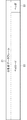
- FIG. 11 is an explanatory diagram illustrating an example of a method for measuring the delay time.
- control frames are transmitted simultaneously from four lines.
- control frames are received at different timings depending on the bandwidth of each line.
- the control frame generation unit 7 selects one line for expanding the output band, and temporarily inserts a large number of dummy frames into the line.
- the control frame processing unit 11 can widen the output bandwidth. Judge that there is.
- the control frame generation unit 7 generates a control frame in which the relative delay amount is added to the delay measurement information 39 of the control frame 32. By adding a delay amount to the delay measurement information 39, the delay amount is transmitted between the communication device 1 and the communication device 15.
- the state transition between the output bandwidth increase mode and the output bandwidth reduction mode is executed at the following timing.
- the mode is shifted to the output bandwidth reduction mode.
- the control frame processing unit 11 determines that the output band is not a target to be narrowed in the output band reduction mode (that is, when the counter device transmission frame number 33 is the same as the own device reception frame number 35), the mode shifts to the output band increase mode. Is done.
- the dividing unit 4 divides the input frame, the allocating unit 6 distributes the divided frames according to the output bands of a plurality of lines, and each arbitrating unit 9 The sorted frame is transmitted.
- the allocating unit 6 sends a frame to the line having the smallest remaining output weight indicating the ratio of the remaining number of bytes that can be output per unit time to the number of bytes that can be output per unit time set as the output band.
- the arbitrating unit 9 transmits a dummy frame corresponding to the remaining data amount for each reset period. Therefore, when data transfer is performed using a plurality of communication lines, it is possible to suppress a deviation in the amount of data transferred by each line.
- the arbitration unit 9 transmits a control frame including the amount of transmission data transmitted from each line to another device.
- This control frame is generated by the control frame generator 7.
- the filter part 10 receives the control frame transmitted from the communication apparatus 15 according to transmission of a control frame.
- This control frame includes the amount of received data received by the communication device 15.
- the band management unit 5 sets the output band of the line that transmitted the control frame to be narrow.
- the control frame generation unit 7 increases the data amount of the dummy frame to be transmitted and the band management unit 5 does not cause a delay due to the increase of the dummy frame
- the output bandwidth of the line transmitted by increasing the number of dummy frames is set widely according to the increased amount of dummy frame data.
- the output bandwidth setting of each line can be dynamically adjusted, so that such a problem can be solved.
- the communication device 1 (communication device 15) has not only the function of efficiently distributing frames but also the function of adjusting the output bandwidth has been described.
- the communication device may not have a function of adjusting the output band.
- the communication device may include one or both of a function of adjusting the output band and a function of expanding the output band and a function of narrowing the output band.
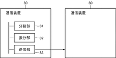
- FIG. 12 is a block diagram showing an outline of a communication apparatus according to the present invention.
- the communication device according to the present invention is a communication device (for example, the communication device 1 or the communication device 15) that performs data transfer using a plurality of lines, and a dividing unit 81 (for example, the dividing unit 4) that divides an input frame. ) And an output band of a plurality of lines (for example, according to an output band of each line managed by the band management unit 5), and a distribution unit 82 (for example, the band management unit 5, The distribution unit 6) and the transmission unit 83 (for example, the arbitration unit 9) that transmits the distributed frame are provided.
- a communication device for example, the communication device 1 or the communication device 15
- a dividing unit 81 for example, the dividing unit 4
- an output band of a plurality of lines for example, according to an output band of each line managed by the band management unit 5
- a distribution unit 82 for example, the band management unit 5
- the allocating unit 82 has a predetermined period (for example, a reset period) on the line with respect to the amount of data (for example, the number of bytes that can be output per unit time) that can be output per unit time set as an output band for each line
- the frame is allocated to the line having the smallest remaining output weight indicating the ratio of the remaining data amount (for example, the remaining number of bytes that can be output).
- the transmission unit 83 transmits a dummy frame (for example, a dummy frame 40) corresponding to the remaining data amount when a predetermined period has elapsed.
- the transmission unit 83 transmits a control frame (for example, the control frame 32) including the transmission data amount (for example, the number of own device transmission frames 37 and the number of own device transmission bytes 38) transmitted from each line to another device. May be.
- the distribution unit 82 receives a control frame transmitted from another device (for example, the communication device 15) in response to the transmission of the control frame, and receives other control frames included in the control frame.
- the output band of the line on which the control frame is transmitted for example, by the bandwidth management unit 5 You may set so that it may become narrow.
- the allocating unit 82 may determine the output band to be set based on the amount of received data (for example, Equation 2 above) received by another device with respect to the control frame transmission interval. .
- the transmission unit 83 may increase the data amount of the dummy frame to be transmitted.
- the allocating unit 82 (for example, the bandwidth management unit 5) increases the data amount of the dummy frame by increasing the output bandwidth of the line transmitted by increasing the dummy frame when there is no delay due to the increase of the dummy frame. It may be set so as to widen depending on.
- the output band based on the delay of the dummy frame, it is possible to suppress the influence when transmitting the data frame.
- data can be efficiently transmitted by widening the output band in this way.
- the transmission unit 83 may increase the number of dummy frames within a range where no frame loss occurs.
- FIG. 13 is a block diagram showing an outline of a communication system according to the present invention.
- the communication system according to the present invention includes a plurality of communication devices 80 that perform data transfer using a plurality of lines. Note that the content of the communication device 80 is the same as the content of the communication device 80 illustrated in FIG.
- the transmission unit 83 (for example, the arbitration unit 9) of the first communication device 80 (for example, the communication device 1) transmits a transmission data amount (for example, own device transmission) transmitted from each line.
- a control frame including the frame number 37 and the own device transmission byte number 38) is transmitted to the second communication device 80 (for example, the communication device 15).
- the transmission unit 83 (for example, the arbitration unit 9) of the second communication device 80 receives the received data amount (for example, the counter device transmission frame number 33, the counter device transmission byte number 34, the host device reception frame number). 35, the control frame in which the own device received byte number 36) is set is transmitted to the first communication device 80.
- the distribution unit 82 (for example, the control frame processing unit 11 and the bandwidth management unit 5) of the first communication device 80 determines that the received data amount included in the control frame received from the second communication device 80 is greater than the transmission data amount. Is set so that the output band of the line that transmitted the control frame is narrow.
- a frame is allocated to a line with the smallest remaining output weight indicating the ratio of the remaining data amount that can be output every predetermined period on the line, and the remaining data is transmitted when the predetermined period elapses in the transmission process.
- the present invention is preferably applied to a communication apparatus that aggregates a plurality of communication lines and performs data transfer.
- Examples of the communication line include an Ethernet (registered trademark) network and a line for performing communication using a packet or a cell.
Landscapes
- Engineering & Computer Science (AREA)
- Computer Networks & Wireless Communication (AREA)
- Signal Processing (AREA)
- Environmental & Geological Engineering (AREA)
- Data Exchanges In Wide-Area Networks (AREA)
Abstract
Description
フレーム1、フレーム2およびフレーム3が送信部3に入力されると、分割部4は、各フレームを分割し、分割したフレームにシーケンス番号、先頭フラグおよび末尾フラグを付与して、振分部6に入力する。先頭フラグは、分割されたフレームの先頭のデータか否かを識別するフラグであり、末尾フラグは、分割されたフレームの末尾のデータか否かを識別するフラグである。
また、ダミーフラグ30は、ダミーフレームを示すフィールドのため、0が設定される。
対向装置送信バイト数34は、対向する通信装置から送信されたフレームのバイト数を示す。自装置受信フレーム数35は、対向する通信装置から受信したフレーム数を示す。自装置受信バイト数36は、対向する通信装置から受信したフレームのバイト数を示す。自装置送信フレーム数37は、自通信装置が送信するフレーム数を表す。自装置送信バイト数38は、自通信装置が送信するフレームのバイト数を表す。遅延測定情報39は、フレーム送信を送信した際に測定される遅延時間を表す。なお、制御フレームに含まれる各フィールドを利用する方法は、後述の出力帯域調整機能の説明において、説明される。
次に、振分部6が分割後のフレームを振り分ける方法を説明する。帯域管理部5は、出力帯域として各回線に設定される単位時間に出力可能なデータ量と、その回線で所定の周期ごとに出力可能な残りのデータ量を管理する。具体的には、帯域管理部5は、単位時間に出力可能なデータ量として単位時間当たりの出力可能バイト数を保持し、所定の周期ごとに出力可能な残りのデータ量として残り出力可能バイト数を回線ごとに保持している。
この単位時間は、任意の単位で固定的に設定される。
図9は、残り出力可能バイト数が一番大きい回線にフレームを出力する場合の動作例を示す説明図である。
次に、出力帯域を調整する方法を説明する。図10は、出力帯域を調整する方法の例を示す説明図である。図10に例示する実線矢印は、フレームの流れを示し、点線矢印は、制御フレームの流れを示す。出力帯域調整機能には、出力帯域を広げる機能と、出力帯域を狭める機能とが含まれる。以下、出力帯域を広げる機能を実行している状態を、出力帯域増加モードと記し、出力帯域を狭める機能を実行している状態を、出力帯域削減モードと記す。本実施形態において、初期状態では、出力帯域削減モードになっているものとし、出力帯域を狭める処理が行われるとする。
= 単位時間×制御フレーム処理部11から通知された出力帯域 …(式3)
通信回線として、例えば、Ethernet(登録商標)網や、パケットやセルを利用して通信を行う回線が挙げられる。
2 受信部
3 送信部
4 分割部
5 帯域管理部
6 振分部
7 制御フレーム生成部
8 格納部
9 調停部
10 フィルタ部
11 制御フレーム処理部
12 格納部
13 読出部
14 結合部
Claims (10)
- 複数の回線を用いてデータ転送を行う通信装置であって、
入力されたフレームを分割する分割手段と、
前記複数の回線の出力帯域に応じて、分割されたフレームを振り分ける振分手段と、
振り分けられたフレームを送信する送信手段とを備え、
前記振分手段は、前記出力帯域として各回線に設定される単位時間に出力可能なデータ量に対し、当該回線で所定の周期ごとに出力可能な残りのデータ量の割合を示す残り出力重みが最も小さい回線にフレームを振り分け、
前記送信手段は、前記所定の周期経過時に前記残りのデータ量に相当するダミーフレームを送信する
ことを特徴とする通信装置。 - 前記送信手段は、各回線から送信される送信データ量を含む制御フレームを他の装置に送信し、
前記振分手段は、前記制御フレームの送信に応じて前記他の装置から送信される制御フレームを受信し、当該制御フレームに含まれる前記他の装置が受信した受信データ量が、前記送信データ量よりも小さい場合に、前記制御フレームを送信した回線の出力帯域が狭くなるように設定する
請求項1記載の通信装置。 - 前記振分手段は、制御フレームを送信する間隔に対する、他の装置が受信した受信データ量に基づいて、設定する出力帯域を決定する
請求項2記載の通信装置。 - 前記送信手段は、送信するダミーフレームのデータ量を増加させ、
前記振分手段は、前記ダミーフレームの増加による遅延が生じない場合に、ダミーフレームを増加させて送信した回線の出力帯域を、増加させたダミーフレームのデータ量に応じて広くなるように設定する
請求項1から請求項3のうちのいずれか1項に記載の通信装置。 - 前記送信手段は、フレームロスを発生させない範囲でダミーフレームを増加させる
請求項4記載の通信装置。 - 複数の回線を用いてデータ転送を行う通信装置を複数備え、
前記通信装置は、
入力されたフレームを分割する分割手段と、
前記複数の回線の出力帯域に応じて、分割されたフレームを振り分ける振分手段と、
振り分けられたフレームを送信する送信手段とを含み、
前記振分手段は、前記出力帯域として各回線に設定される単位時間に出力可能なデータ量に対し、当該回線で所定の周期ごとに出力可能な残りのデータ量の割合を示す残り出力重みが最も小さい回線にフレームを振り分け、
前記送信手段は、前記所定の周期経過時に前記残りのデータ量に相当するダミーフレームを送信する
ことを特徴とする通信システム。 - 第一の通信装置の前記送信手段は、各回線から送信される送信データ量を含む制御フレームを第二の通信装置に送信し、
前記第二の通信装置の前記送信手段は、自通信装置が受信した受信データ量を設定した制御フレームを前記第一の通信装置に送信し、
前記第一の通信装置の前記振分手段は、前記第二の通信装置から受信した制御フレームに含まれる前記受信データ量が、前記送信データ量よりも小さい場合に、前記制御フレームを送信した回線の出力帯域が狭くなるように設定する
請求項6記載の通信システム。 - 複数の回線を用いてデータ転送を行う場合の通信方法であって、
入力されたフレームを分割し、
出力帯域として各回線に設定される単位時間に出力可能なデータ量に対し、当該回線で所定の周期ごとに出力可能な残りのデータ量の割合を示す残り出力重みが最も小さい回線に、分割されたフレームを振り分け、
振り分けられたフレームと、前記所定の周期経過時に前記残りのデータ量に相当するダミーフレームとを送信する
ことを特徴とする通信方法。 - 各回線から送信される送信データ量を含む制御フレームを他の装置に送信し、
前記制御フレームの送信に応じて前記他の装置から送信される制御フレームを受信し、 前記制御フレームに含まれる前記他の装置が受信した受信データ量が、前記送信データ量よりも小さい場合に、前記制御フレームを送信した回線の出力帯域が狭くなるように設定する
請求項8記載の通信方法。 - 複数の回線を用いてデータ転送を行うコンピュータに適用される通信用プログラムが記憶された記憶媒体であって、
前記コンピュータに、
入力されたフレームを分割する分割処理、
前記複数の回線の出力帯域に応じて、分割されたフレームを振り分ける振分処理、および、
振り分けられたフレームを送信する送信処理を実行させ、
前記振分処理で、前記出力帯域として各回線に設定される単位時間に出力可能なデータ量に対し、当該回線で所定の周期ごとに出力可能な残りのデータ量の割合を示す残り出力重みが最も小さい回線にフレームを振り分けさせ、
前記送信処理で、前記所定の周期経過時に前記残りのデータ量に相当するダミーフレームを送信させる
ための通信用プログラムが記憶された記憶媒体。
Priority Applications (6)
| Application Number | Priority Date | Filing Date | Title |
|---|---|---|---|
| CA2946508A CA2946508A1 (en) | 2014-05-08 | 2015-05-07 | Communication device, communication system, communication method, and storage medium storing program for communication |
| US15/309,520 US10142247B2 (en) | 2014-05-08 | 2015-05-07 | Communication device, communication system, communication method, and storage medium storing program transferring data using a plurality of lines |
| JP2016517816A JP6195017B2 (ja) | 2014-05-08 | 2015-05-07 | 通信装置、通信システム、通信方法および通信用プログラムが記憶された記憶媒体 |
| EP15789544.2A EP3142308A4 (en) | 2014-05-08 | 2015-05-07 | Communication device, communication system, communication method, and storage medium storing program for communication |
| CN201580024088.3A CN106464607B (zh) | 2014-05-08 | 2015-05-07 | 通信设备、通信系统、通信方法和存储用于通信的程序的存储介质 |
| RU2016147933A RU2648566C1 (ru) | 2014-05-08 | 2015-05-07 | Устройство связи, система связи, способ связи и запоминающий носитель, хранящий программу для осуществления связи |
Applications Claiming Priority (2)
| Application Number | Priority Date | Filing Date | Title |
|---|---|---|---|
| JP2014-096762 | 2014-05-08 | ||
| JP2014096762 | 2014-05-08 |
Publications (1)
| Publication Number | Publication Date |
|---|---|
| WO2015170475A1 true WO2015170475A1 (ja) | 2015-11-12 |
Family
ID=54392331
Family Applications (1)
| Application Number | Title | Priority Date | Filing Date |
|---|---|---|---|
| PCT/JP2015/002320 WO2015170475A1 (ja) | 2014-05-08 | 2015-05-07 | 通信装置、通信システム、通信方法および通信用プログラムが記憶された記憶媒体 |
Country Status (7)
| Country | Link |
|---|---|
| US (1) | US10142247B2 (ja) |
| EP (1) | EP3142308A4 (ja) |
| JP (1) | JP6195017B2 (ja) |
| CN (1) | CN106464607B (ja) |
| CA (1) | CA2946508A1 (ja) |
| RU (1) | RU2648566C1 (ja) |
| WO (1) | WO2015170475A1 (ja) |
Families Citing this family (3)
| Publication number | Priority date | Publication date | Assignee | Title |
|---|---|---|---|---|
| JP2016105550A (ja) * | 2014-12-01 | 2016-06-09 | 富士通株式会社 | 伝送装置、伝送網システム、及び伝送遅延測定方法 |
| CN109951738B (zh) * | 2017-12-21 | 2022-02-01 | 腾讯数码(天津)有限公司 | 传输路径获取方法、第一电子设备以及可读存储介质 |
| JP7317630B2 (ja) * | 2019-08-14 | 2023-07-31 | キヤノン株式会社 | 画像処理装置、画像処理方法、及びプログラム |
Citations (3)
| Publication number | Priority date | Publication date | Assignee | Title |
|---|---|---|---|---|
| WO2004051955A1 (ja) * | 2002-11-29 | 2004-06-17 | Fujitsu Limited | 通信装置、制御方法及びプログラム |
| JP2010171562A (ja) * | 2009-01-21 | 2010-08-05 | Fujitsu Ltd | 通信装置および通信制御方法 |
| JP2011103614A (ja) * | 2009-11-12 | 2011-05-26 | Hitachi Ltd | パケット振り分け機能を有する装置及びパケット振り分け方式 |
Family Cites Families (9)
| Publication number | Priority date | Publication date | Assignee | Title |
|---|---|---|---|---|
| US6055268A (en) * | 1996-05-09 | 2000-04-25 | Texas Instruments Incorporated | Multimode digital modem |
| US5918021A (en) | 1996-06-03 | 1999-06-29 | Intel Corporation | System and method for dynamic distribution of data packets through multiple channels |
| US6813284B2 (en) | 2001-01-17 | 2004-11-02 | Qualcomm Incorporated | Method and apparatus for allocating data streams given transmission time interval (TTI) constraints |
| US7151749B2 (en) | 2001-06-14 | 2006-12-19 | Microsoft Corporation | Method and System for providing adaptive bandwidth control for real-time communication |
| WO2004114610A1 (ja) | 2003-06-18 | 2004-12-29 | Nippon Telegraph And Telephone Corporation | 無線パケット通信方法 |
| CN101060518B (zh) * | 2007-06-05 | 2012-11-14 | 中兴通讯股份有限公司 | 一种多线路绑定的业务信息发送和接收设备 |
| US7908393B2 (en) | 2007-12-04 | 2011-03-15 | Sony Computer Entertainment Inc. | Network bandwidth detection, distribution and traffic prioritization |
| JP5359202B2 (ja) * | 2008-11-06 | 2013-12-04 | 富士通株式会社 | フレーム生成装置、光伝送システム、フレーム生成方法および光伝送方法 |
| EP3050354B1 (en) * | 2013-09-25 | 2020-04-29 | Intel Corporation | End-to-end (e2e) tunneling for multi-radio access technology (multi-rat) |
-
2015
- 2015-05-07 CN CN201580024088.3A patent/CN106464607B/zh not_active Expired - Fee Related
- 2015-05-07 CA CA2946508A patent/CA2946508A1/en not_active Abandoned
- 2015-05-07 EP EP15789544.2A patent/EP3142308A4/en not_active Withdrawn
- 2015-05-07 RU RU2016147933A patent/RU2648566C1/ru active
- 2015-05-07 WO PCT/JP2015/002320 patent/WO2015170475A1/ja active Application Filing
- 2015-05-07 US US15/309,520 patent/US10142247B2/en not_active Expired - Fee Related
- 2015-05-07 JP JP2016517816A patent/JP6195017B2/ja not_active Expired - Fee Related
Patent Citations (3)
| Publication number | Priority date | Publication date | Assignee | Title |
|---|---|---|---|---|
| WO2004051955A1 (ja) * | 2002-11-29 | 2004-06-17 | Fujitsu Limited | 通信装置、制御方法及びプログラム |
| JP2010171562A (ja) * | 2009-01-21 | 2010-08-05 | Fujitsu Ltd | 通信装置および通信制御方法 |
| JP2011103614A (ja) * | 2009-11-12 | 2011-05-26 | Hitachi Ltd | パケット振り分け機能を有する装置及びパケット振り分け方式 |
Non-Patent Citations (1)
| Title |
|---|
| See also references of EP3142308A4 * |
Also Published As
| Publication number | Publication date |
|---|---|
| JP6195017B2 (ja) | 2017-09-13 |
| RU2648566C1 (ru) | 2018-03-26 |
| CN106464607A (zh) | 2017-02-22 |
| US20170155593A1 (en) | 2017-06-01 |
| JPWO2015170475A1 (ja) | 2017-04-20 |
| US10142247B2 (en) | 2018-11-27 |
| EP3142308A4 (en) | 2018-01-03 |
| CA2946508A1 (en) | 2015-11-12 |
| CN106464607B (zh) | 2019-09-03 |
| EP3142308A1 (en) | 2017-03-15 |
Similar Documents
| Publication | Publication Date | Title |
|---|---|---|
| US9699091B2 (en) | Apparatus and method for time aware transfer of frames in a medium access control module | |
| US10680949B2 (en) | Systems and methods for implementing a time-stamped controller area network (CAN) bus message | |
| US9769082B2 (en) | System and method for network bandwidth, buffers and timing management using hybrid scheduling of traffic with different priorities and guarantees | |
| US9998389B2 (en) | Method and apparatus for blocking transmission of frames from a network device | |
| CN104429029B (zh) | 网络中通过中央控制器的基于延迟的业务速率控制 | |
| US8943161B2 (en) | Time synchronization system | |
| JP2019503153A (ja) | サービストラヒック分配方法及び装置 | |
| WO2014083780A1 (ja) | 通信装置、通信装置を有するルータ、バスシステム、およびバスシステムを有する半導体回路の回路基板 | |
| WO2014128802A1 (ja) | インタフェース装置およびバスシステム | |
| US10728134B2 (en) | Methods, systems, and computer readable media for measuring delivery latency in a frame-preemption-capable network | |
| JP6195017B2 (ja) | 通信装置、通信システム、通信方法および通信用プログラムが記憶された記憶媒体 | |
| US20140036672A1 (en) | Calculating credit for controlling data frame transmission | |
| US10361962B2 (en) | Packet processing technique for a communication network | |
| JP2013048415A (ja) | データネットワーク向けエンドツーエンド遅延情報の埋め込み | |
| Wang et al. | Flow distribution-aware load balancing for the datacenter | |
| EP2966819B1 (en) | Method and apparatus for forwarding traffic of switching system | |
| JP2011040895A (ja) | 情報処理装置、その制御方法及びプログラム | |
| US11018968B2 (en) | Packet transmission method and packet transmitting device | |
| WO2016132402A1 (ja) | 通信フレーム転送装置および通信システム | |
| US20180026864A1 (en) | Communication apparatus, communication system, and communication method | |
| CN117459462A (zh) | 网络负载均衡方法和装置 | |
| KR102524579B1 (ko) | 파장 가변 레이저 다이오드의 파장이 변환되는 시간에 기초하여 포토닉 프레임을 전송할 시간을 결정하는 포토닉 프레임 스위칭 시스템 | |
| WO2022244262A1 (ja) | ネットワーク遅延測定システム、ネットワーク遅延測定方法及びネットワーク遅延測定装置 | |
| TW202344022A (zh) | 設備轉換器、通訊系統、通訊方法、及通訊程式產品 | |
| CN117478580A (zh) | 一种发送负载信息的方法、发送报文的方法及装置 |
Legal Events
| Date | Code | Title | Description |
|---|---|---|---|
| 121 | Ep: the epo has been informed by wipo that ep was designated in this application |
Ref document number: 15789544 Country of ref document: EP Kind code of ref document: A1 |
|
| ENP | Entry into the national phase |
Ref document number: 2016517816 Country of ref document: JP Kind code of ref document: A |
|
| ENP | Entry into the national phase |
Ref document number: 2946508 Country of ref document: CA |
|
| NENP | Non-entry into the national phase |
Ref country code: DE |
|
| WWE | Wipo information: entry into national phase |
Ref document number: 15309520 Country of ref document: US |
|
| REEP | Request for entry into the european phase |
Ref document number: 2015789544 Country of ref document: EP |
|
| WWE | Wipo information: entry into national phase |
Ref document number: 2015789544 Country of ref document: EP |
|
| ENP | Entry into the national phase |
Ref document number: 2016147933 Country of ref document: RU Kind code of ref document: A |