WO2015166736A1 - 車両用マスタシリンダ - Google Patents
車両用マスタシリンダ Download PDFInfo
- Publication number
- WO2015166736A1 WO2015166736A1 PCT/JP2015/057821 JP2015057821W WO2015166736A1 WO 2015166736 A1 WO2015166736 A1 WO 2015166736A1 JP 2015057821 W JP2015057821 W JP 2015057821W WO 2015166736 A1 WO2015166736 A1 WO 2015166736A1
- Authority
- WO
- WIPO (PCT)
- Prior art keywords
- cylinder
- piston
- hole
- peripheral surface
- movement
- Prior art date
- Legal status (The legal status is an assumption and is not a legal conclusion. Google has not performed a legal analysis and makes no representation as to the accuracy of the status listed.)
- Ceased
Links
Images


Classifications
-
- B—PERFORMING OPERATIONS; TRANSPORTING
- B62—LAND VEHICLES FOR TRAVELLING OTHERWISE THAN ON RAILS
- B62L—BRAKES SPECIALLY ADAPTED FOR CYCLES
- B62L3/00—Brake-actuating mechanisms; Arrangements thereof
- B62L3/02—Brake-actuating mechanisms; Arrangements thereof for control by a hand lever
- B62L3/023—Brake-actuating mechanisms; Arrangements thereof for control by a hand lever acting on fluid pressure systems
-
- B—PERFORMING OPERATIONS; TRANSPORTING
- B60—VEHICLES IN GENERAL
- B60T—VEHICLE BRAKE CONTROL SYSTEMS OR PARTS THEREOF; BRAKE CONTROL SYSTEMS OR PARTS THEREOF, IN GENERAL; ARRANGEMENT OF BRAKING ELEMENTS ON VEHICLES IN GENERAL; PORTABLE DEVICES FOR PREVENTING UNWANTED MOVEMENT OF VEHICLES; VEHICLE MODIFICATIONS TO FACILITATE COOLING OF BRAKES
- B60T11/00—Transmitting braking action from initiating means to ultimate brake actuator without power assistance or drive or where such assistance or drive is irrelevant
- B60T11/10—Transmitting braking action from initiating means to ultimate brake actuator without power assistance or drive or where such assistance or drive is irrelevant transmitting by fluid means, e.g. hydraulic
- B60T11/16—Master control, e.g. master cylinders
- B60T11/236—Piston sealing arrangements
-
- B—PERFORMING OPERATIONS; TRANSPORTING
- B62—LAND VEHICLES FOR TRAVELLING OTHERWISE THAN ON RAILS
- B62L—BRAKES SPECIALLY ADAPTED FOR CYCLES
- B62L3/00—Brake-actuating mechanisms; Arrangements thereof
- B62L3/02—Brake-actuating mechanisms; Arrangements thereof for control by a hand lever
Definitions
- the present invention relates to a vehicular master cylinder.
- This application claims priority based on Japanese Patent Application No. 2014-093101 for which it applied on April 28, 2014, and uses the content here.
- a master cylinder having a structure in which a covering member that covers the opening side of the cylinder is attached to the cylinder by a locking member that is locked to the opening of the cylinder, and piston disengagement is regulated through this covering member (for example, Patent Document 1). reference).
- An aspect of the present invention provides a vehicular master cylinder capable of improving manufacturing efficiency.
- the vehicle master cylinder is provided with a movement restricting member that is inserted into a radial hole formed in the cylinder and restricts the movement of the piston with respect to the cylinder.
- the movement restricting member is configured to fix the detection member that detects the operation of the operation element to the cylinder.
- the cylinder is provided integrally with the cylinder main body member together with the support portion to which the operation element is attached and the reservoir in which the brake fluid is stored. It is a screw member which fixes a detection member to the cylinder body member.
- the screw member is disposed such that the tip side thereof can come into contact with the piston, and restricts the movement of the piston.
- the movement restricting member restricts the movement of the piston via a piston abutting member disposed in the cylinder and abutting on the piston.
- the piston abutting member is a circumferential member extending in the circumferential direction of the cylinder, and one end side of the piston abutting member abuts on the piston, and the movement restriction An inclined portion extending toward the other end side of the piston contact member and inward in the radial direction is formed at a portion pressed by the member.
- the piston contact member holds the other side of the flexible protective member that is held by the piston and covers the opening side of the cylinder.
- the manufacturing efficiency is improved.
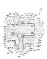
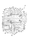
- FIG. 4 is a sectional view taken along line XX of FIG. 3 showing the first embodiment according to the present invention. It is an expanded sectional view of the principal part of FIG. 4 which shows 1st Embodiment which concerns on this invention. It is an expanded sectional view of the principal part corresponding to Drawing 5 showing a 2nd embodiment concerning the present invention. It is an expanded sectional view of the principal part corresponding to Drawing 5 showing a 3rd embodiment concerning the present invention. It is an expanded sectional view of the important section corresponding to Drawing 5 showing a 4th embodiment concerning the present invention.
- the reservoir 10 is a reservoir-integrated vehicular master cylinder 11 that constitutes a part of the vehicular master cylinder 11.
- This vehicle master cylinder 11 is for straddle-type vehicles such as motorcycles, three-wheel buggies, and four-wheel buggies that are attached in a state of being exposed to the outside.
- the vehicle master cylinder 11 including the reservoir 10 is described as being attached to the vehicle.
- the front in the vehicle is “front”
- the rear in the vehicle is “rear”
- the left in the vehicle is “left”.
- the right side of the vehicle will be described as “right”.
- the first embodiment is a vehicle master cylinder 11 for front wheel braking that is operated by the driver's right hand.
- the present invention is also applicable to a rear wheel braking master cylinder and a clutch master cylinder operated by the driver's left hand, in which case the left and right in the following description are reversed.
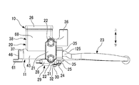
- the vehicle master cylinder 11 is attached to the mounting portion 16 of the steering bar 15 indicated by a two-dot chain line in FIG.
- the mounting portion 16 is a portion that is located on the right side of the steering bar 15 and extends in the left-right direction.
- the steering bar 15 is formed by appropriately bending a cylindrical pipe member, and at least the outer peripheral surface of the mounting portion 16 to which the vehicle master cylinder 11 is attached is cylindrical.
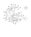
- the vehicular master cylinder 11 is made of metal, the main body member 20 shown in FIG. 1, the holder 21, the two mounting bolts 22 and 22 shown in FIGS. 2 and 3, and the brake lever 23 (operator).
- the vehicle master cylinder 11 includes a brake switch 29 (detection member) having a synthetic resin case 28 shown in FIGS. 2 and 3, a metal mounting screw member 30 (movement restricting member), and a latch. It has the washer 31 and the spring washer 32, and the diaphragm 33 which consists of elastic materials, such as rubber
- the brake switch 29 is provided to turn on or off a contact inside the brake switch 29 by operating the brake lever 23 to light a brake lamp (not shown) of the vehicle.
- the case 28 of the brake switch 29 is made of synthetic resin, but may be made of metal or rubber.
- the main body member 20 is an integrally molded product by casting, and is disposed on the front side of the mounting portion 16 of the steering bar 15 as shown in FIG.
- a mounting seat 34 is formed on the right side of the main body member 20 so as to protrude rearward.
- the body member 20 is attached to the steering bar 15 by sandwiching the mounting portion 16 of the steering bar 15 between the mounting seat portion 34 and the holder 21.
- the mounting seat 34 and the holder 21 are coupled by two upper and lower mounting bolts 22 and 22 shown in FIGS. 2 and 3 to sandwich the steering bar 15.
- the main body member 20 is formed with a pair of upper and lower plate-like lever support portions 35 and 35 so as to protrude forward as shown in FIG.
- the brake lever 23 is inserted between these lever support portions 35 and 35.
- the support bolt 24 is inserted into the one lever support portion 35, the brake lever 23, and the other lever support portion 35 along the vertical direction and screwed into the support nut 25.
- the brake lever 23 is rotatably supported by the lever support portions 35 and 35, the support bolt 24, and the support nut 25.
- the brake lever 23 rotates around the support bolt 24.
- the brake lever 23 extends rightward from the main body member 20 along the steering bar 15 in front of the steering bar 15.
- the main body member 20 is formed with a mirror mounting portion 36 to which a rearview mirror (not shown) is attached further above the upper lever support portion 35 shown in FIG. 3, that is, as shown in FIG.
- the main body member 20 is provided with a cylinder 37 extending leftward from the base end side of the lever support portions 35 and 35.
- the cylinder 37 is disposed in front of the steering bar 15 shown in FIG. 1 so as to follow the axial direction of the mounting portion 16.
- the cylinder 37 is formed in the lower part of the main body member 20 as shown in FIG.
- a reservoir wall 38 is formed on the upper part of the main body member 20, that is, on the upper side of the cylinder 37.
- the reservoir wall portion 38 has a cylindrical shape along the vertical direction, and a reservoir chamber 40 in which brake fluid is stored is formed on the inner side by a reservoir bottom portion 39 that closes the cylinder 37 side.
- the reservoir bottom 39 also constitutes the upper part of the cylinder 37.
- the cylinder 37 has a bottomed cylindrical shape having a cylinder tube portion 45 extending in the left-right direction and a cylinder bottom portion 46 disposed on the opposite side to the lever support portions 35, 35 of the cylinder tube portion 45.
- a cylinder hole 47 having an opening 48 on the lever support portions 35, 35 side is formed inside the cylinder tube portion 45 and the cylinder bottom portion 46.
- the cylinder hole 47 is along the axial direction of the mounting portion 16 of the steering bar 15 shown in FIG.
- the cylinder hole 47 includes a main hole 51 on the cylinder bottom 46 side, a tapered hole 52 on the opposite side of the main hole 51 with respect to the cylinder bottom 46, and a main hole of the tapered hole 52.
- 51 has a mouth hole 53 on the opposite side to 51.
- the end of the mouth hole 53 opposite to the main hole 51 constitutes an opening 48 of the cylinder 37.
- the main hole 51, the tapered hole 52, and the mouth hole 53 are aligned with the central axis, and this central axis is the central axis of the cylinder hole 47.
- the center axis of the cylinder hole 47 is set as the center axis of the cylinder 37.
- this central axis is referred to as a cylinder axis
- a direction along the central axis is referred to as a cylinder axis direction
- a direction perpendicular to the central axis of the cylinder 37 is referred to as a cylinder radial direction
- a direction around the central axis of the cylinder 37 is referred to as a cylinder axis. This is called the circumferential direction.
- the main hole portion 51 has a cylindrical inner peripheral surface 51a.
- the tapered hole portion 52 has a tapered diameter-expanded inner peripheral surface 52a that extends toward the opening portion 48 while expanding the diameter from the end edge portion on the opening portion 48 side of the inner peripheral surface 51a, and the diameter-expanded inner peripheral surface 52a.
- the inner peripheral surface 51a has a taper-shaped enlarged inner peripheral surface 52b extending from the opposite edge to the opening 48 side.
- the taper amount obtained by dividing the difference in diameter between both ends in the cylinder axis direction by the distance between both ends in the cylinder axis direction is larger on the enlarged inner peripheral surface 52b than on the enlarged inner peripheral surface 52a.
- the mouth hole 53 is reduced in diameter from a cylindrical inner peripheral surface 53a and an end edge on the opposite side to the opening 48 of the inner peripheral surface 53a, and extends to the opposite side with respect to the opening 48. It has an inner peripheral surface 53b and a bottom surface 53c extending inward in the cylinder radial direction from the inner peripheral edge of the reduced diameter inner peripheral surface 53b.
- the inner peripheral edge portion of the bottom surface 53 c is connected to the opposite side of the enlarged inner peripheral surface 52 a of the enlarged inner peripheral surface 52 b of the tapered hole portion 52.
- the bottom surface 53c is parallel to a surface orthogonal to the cylinder axis.
- the main hole portion 51 is longer in the cylinder axial direction than the mouth hole portion 53, and is the longest in the cylinder hole 47 in the cylinder axial direction.
- the main hole 51 has an inner diameter that is smaller than that of the mouth hole 53, and is the smallest in the cylinder radial direction in the cylinder hole 47.
- the mouth hole 53 is disposed on the most opposite side to the cylinder bottom 46 in the cylinder hole 47.
- a mounting seat 54 to which the brake switch 29 is attached is formed in the cylinder tube portion 45 at the outer lower portion near the boundary between the main hole portion 51 and the mouth hole portion 53.
- the mounting seat 54 has a main seat portion 55 on the main hole portion 51 side in the cylinder axial direction, and a protruding seat portion 56 on the mouth hole portion 53 side in the cylinder axial direction that projects downward from the main seat portion 55. Yes.
- the wall portion 57 on the main seat portion 55 side of the projecting seat portion 56 is parallel to a plane orthogonal to the cylinder axis.
- the mounting seat 54 has a step shape.
- a radial hole 58 parallel to the cylinder radial direction is formed at the position of the protruding seat portion 56 of the mounting seat 54.
- the radial hole 58 is a screw hole, and is formed upward from the lower surface of the projecting seat portion 56 perpendicular to the lower surface.
- the radial hole 58 opens in the inner peripheral surface 53 a of the mouth hole portion 53.
- a threaded hole 59 is formed in the cylinder bottom 46 so as to penetrate the cylinder bottom 46.
- the screw hole 59 is screwed with a bolt that attaches the base of the brake pipe to the cylinder 37.
- a passage for communicating the inside of the main hole 51 and the brake pipe is formed in this bolt.
- the brake pipe communicates with a wheel cylinder of a brake device such as a disc brake provided on the wheel side.
- the cylinder bottom portion 46 is formed with a restricting convex portion 61 that protrudes on the opposite side to the cylinder tube portion 45 and restricts the rotation of the base of the brake pipe.
- the reservoir bottom 39 is formed with a first communication hole 62 that communicates the inside of the main hole 51 and the storage chamber 40 in parallel to the cylinder radial direction.
- the first communication hole 62 is a stepped hole that gradually decreases in diameter from the storage chamber 40 side to the main hole 51 side.
- a second communication hole (not shown) is formed in the reservoir bottom 39 on the cylinder bottom 46 side of the first communication hole 62.
- the reservoir wall portion 38 includes a side wall portion 65 disposed on the cylinder bottom 46 side, that is, the left side, a front wall portion 66 disposed on the front side, and a side wall portion 67 disposed on the opposite side, that is, the right side with respect to the cylinder bottom portion 46. And a rear wall portion 68 shown in FIG. 2 disposed on the rear side. That is, the reservoir wall portion 38 has a rectangular cylindrical shape.
- the reservoir wall portion 38 is formed to surround the storage chamber 40 shown in FIG. 4 by the side wall portion 65, the front wall portion 66, the side wall portion 67 and the rear wall portion 68 shown in FIG. It is open.
- the diaphragm 33 includes a frame-shaped plate portion 69 having a rectangular frame shape placed on the upper surface of the reservoir wall portion 38, and a cylindrical outer tube extending downward from the inner peripheral edge of the frame-shaped plate portion 69.
- a frame-like lower plate portion 71 extending inward from the lower edge of the outer tubular portion 70, and a cylindrical intermediate tube extending upward from the inner peripheral edge of the lower plate portion 71
- an upper plate portion 73 that extends inwardly from the upper end edge of the intermediate cylindrical portion 72.
- the outer cylindrical portion 70, the lower plate portion 71, the intermediate cylindrical portion 72, and the upper plate portion 73 are disposed in the storage chamber 40.
- the diaphragm 33 divides the storage chamber 40 into a liquid chamber 74 that stores brake fluid below the diaphragm 33 and an air chamber 75 that communicates with the atmosphere above the diaphragm 33.
- the diaphragm 33 can follow the variation in the amount of brake fluid in the fluid chamber 74 by being deformed.
- the lid member 26 is an integrally formed product by casting, and covers the diaphragm 33 on the upper side.
- the lower surface of the lid member 26 sandwiches the frame-shaped plate portion 69 of the diaphragm 33 with the upper surface of the reservoir wall portion 38.
- the lid member 26 is fixed to the reservoir wall portion 38 shown in FIG. 4 by mounting screws 27, 27 shown in FIG.
- the diaphragm 33 is directly sandwiched between the reservoir wall 38 of the main body member 20 and the lid member 26.
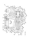
- the vehicle master cylinder 11 includes a return spring 76, a piston 77, a cup seal 78, a cup seal 79, and a boot 80. These are all disposed in the cylinder hole 47 described above.
- the boot 80 includes a boot body 81 and a rigid ring 82.
- the return spring 76, the piston 77, and the rigid ring 82 are made of metal, and the cup seal 78, the cup seal 79, and the boot body 81 are made of an elastic material such as rubber.
- the piston 77 includes a columnar shaft portion 85, a disk-shaped flange portion 86, a columnar shaft portion 87, a disk-shaped flange portion 88, a columnar shaft portion 89, and a disk-shaped shaft portion. It has a flange portion 90, a columnar shaft portion 91, a disk-shaped flange portion 92, a columnar shaft portion 93, a columnar shaft portion 94, and a disk-shaped flange portion 95. These are formed coaxially with a common central axis.
- the shaft portion 85 is formed on the cylinder bottom 46 side of the piston 77, that is, on the left side.
- the flange portion 86 is disposed on the opposite side to the cylinder bottom portion 46 of the shaft portion 85, that is, on the right side.
- the outer diameter of the flange portion 86 is larger than the outer diameter of the shaft portion 85.
- the shaft portion 87 is disposed on the opposite side of the shaft portion 85 of the flange portion 86.
- the outer diameter of the shaft portion 87 is smaller than the outer diameter of the shaft portion 85.
- the flange portion 88 is disposed on the opposite side to the flange portion 86 of the shaft portion 87.
- the outer diameter of the flange portion 88 is larger than the outer diameter of the flange portion 86.
- the shaft portion 89 is disposed on the opposite side to the shaft portion 87 of the flange portion 88.
- the shaft portion 89 has an outer diameter smaller than the outer diameter of the flange portion 88.
- the flange portion 90 is disposed on the opposite side to the flange portion 88 of the shaft portion 89.
- the outer diameter of the flange portion 90 is the same as the outer diameter of the flange portion 88.
- the shaft portion 91 is disposed on the opposite side to the shaft portion 89 of the flange portion 90.
- the shaft portion 91 has an outer diameter smaller than the outer diameter of the flange portion 90.
- the flange portion 92 is disposed on the opposite side of the flange portion 90 of the shaft portion 91.
- the outer diameter of the flange portion 92 is the same as the outer diameter of the flange portion 90.
- the shaft portion 93 is disposed on the opposite side of the shaft portion 91 of the flange portion 92.
- the shaft portion 93 has an outer diameter smaller than the outer diameter of the flange portion 92.
- the shaft portion 94 is disposed on the opposite side to the flange portion 92 of the shaft portion 93.
- the outer diameter of the shaft portion 94 is smaller than the outer diameter of the shaft portion 93.
- the flange portion 95 is disposed on the opposite side to the shaft portion 93 of the shaft portion 94.
- the outer diameter of the flange portion 95 is larger than the outer diameter of the shaft portion 94 and is the same diameter as the outer diameter of the shaft portion 93.
- the flange portion 95 is formed on the most opposite side of the piston 77 with respect to the cylinder bottom portion 46.
- the piston 77 is slidably fitted to the inner peripheral surface 51a of the main hole portion 51 of the cylinder hole 47 at the flange portions 88, 90, and 92. Accordingly, the piston 77 is slidably provided on the cylinder 37 and moves in the cylinder axial direction.
- the return spring 76 is a tapered coil spring whose one end side in the cylinder axial direction has a larger diameter than the other end side, abuts against the cylinder bottom 46 at the end on the large diameter side, and the piston 77 on the inside at the end on the small diameter side.
- the shaft portion 85 is inserted into contact with the flange portion 86.
- the cup seal 78 has a C shape in which one side shape of the cross section on the surface including the central axis opens to one side in the cylinder axial direction.
- the cup seal 78 is disposed between the flange portions 86 and 88 of the piston 77 and is fitted to the shaft portion 87.
- the cup seal 78 is in a state where the C-shaped opening side is arranged on the flange portion 86 side, and the outer peripheral portion is in sliding contact with the inner peripheral surface 51 a of the main hole portion 51.
- the cup seal 79 has a C-shape in which one side shape of the cross section on the surface including the central axis opens to one side in the cylinder axial direction.
- the cup seal 79 is disposed between the flange portions 90 and 92 of the piston 77 and is fitted to the shaft portion 91.
- the cup seal 79 is in a state in which the C-shaped opening side is disposed on the flange portion 90 side, and the outer peripheral portion is in sliding contact with the inner peripheral surface 51 a of the main hole portion 51.
- the mounting screw member 30 includes a disk-shaped head 105, a columnar screw shaft 106 having a smaller diameter than the head 105 and extending from the head 105, and the head of the screw shaft 106. It has a columnar tip shaft portion 107 extending from the opposite side to the portion 105.
- the head portion 105, the screw shaft portion 106, and the tip shaft portion 107 are formed coaxially.
- the distal end shaft portion 107 includes a cylindrical outer peripheral surface 107a, a reduced diameter outer peripheral surface 107b extending from the end edge portion on the opposite side of the outer peripheral surface 107a with respect to the screw shaft portion 106, and a central axis. And a flat front end surface 107c orthogonal to each other.
- a C-shaped spring washer 32 and an annular locking washer 31 are attached to the attachment screw member 30 in advance by inserting the distal end shaft portion 107 and the screw shaft portion 106 inside thereof.
- the locking washer 31 is locked to the mounting screw member 30 and restricts the spring washer 32 from coming off from the mounting screw member 30.
- the case 28 of the brake switch 29 has a main part 110 and an attachment part 111 that is thinner than this.
- a wall portion 112 is formed on the attachment portion 111 side of the main portion 110 of the case 28 along the vertical direction and along the front-rear direction.
- a through hole 113 penetrating in the thickness direction is formed in the attachment portion 111.
- the mounting screw member 30 in a state where the brake switch 29 is fixed to the cylinder 37 has a length such that the tip shaft portion 107 protrudes inward in the cylinder radial direction from the flange portion 92 of the piston 77.
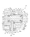
- the brake switch 29 is fixed to the cylinder 37 in a state where the flange portion 92 of the piston 77 is disposed on the opposite side of the opening portion 48 with respect to the tip shaft portion 107 of the mounting screw member 30. Then, even if the piston 77 is pressed by the return spring 76 shown in FIG. 4 and moves in the direction of coming out of the cylinder hole 47, the mounting screw member 30 comes into contact with the flange portion 92 of the piston 77 as shown in FIG. And restrict this movement.
- the mounting screw member 30 is inserted into the radial hole 58 formed in the cylinder 37 and restricts the movement of the piston 77 relative to the cylinder 37.
- the flange portion 92 has a cylindrical outer peripheral surface 92a that is the maximum outer diameter portion, and a reduced diameter that extends toward the shaft portion 93 while reducing the diameter from the end portion of the outer peripheral surface 92a on the shaft portion 93 side. It has an outer peripheral surface 92b and an end surface 92c extending inward in the cylinder radial direction from the reduced diameter outer peripheral surface 92b. The end surface 92c is parallel to a surface orthogonal to the cylinder axis.
- the mounting screw member 30 is in contact with the reduced diameter outer peripheral surface 92b of the flange portion 92 at the reduced diameter outer peripheral surface 107b of the tip shaft portion 107 which is inclined.
- the cylindrical outer peripheral surface 107 a of the distal end shaft portion 107 may be brought into contact with the end surface 92 c of the flange portion 92.
- the brake switch 29 When the brake lever 23 is not operated, the brake switch 29 is pressed by the brake lever 23 to be turned off. When the brake lever 23 is operated and the brake lever 23 is released, the brake switch 29 is turned on. To detect.
- the boot body 81 of the boot 80 has a cylindrical shape and includes a fitting portion 115 at one end, an intermediate flexible portion 116, and a fitting portion 117 at the other end.
- the fitting part 115 and the fitting part 117 are annular.
- the flexible portion 116 has a cylindrical shape that is thinner than the fitting portion 115 and the fitting portion 117 in the cylinder radial direction, and has flexibility.
- a mounting groove 118 is formed inside the fitting portion 117 of the boot body 81 in the cylinder radial direction, and a rigid ring 82 is mounted in the mounting groove 118.
- the fitting portion 115 at one end of the boot main body 81 is disposed between the shaft portion 93 and the flange portion 95 of the piston 77 and is fitted to the shaft portion 94.
- the boot 80 has a flexible portion 116 extending from the outer peripheral side of the fitting portion 115 once extended to the opposite side with respect to the flange portion 92, and then folded back to the outside in the cylinder radial direction so as to be within the mouth hole portion 53.
- the flange portion 92 is extended to the side.
- the boot 80 comes into contact with the inner peripheral surface 53 a of the mouth hole portion 53 in a state where the fitting portion 117 at the other end is prevented from being deformed in the cylinder radial direction by the rigid ring 82.
- the boot 80 holds the one fitting portion 115 on the piston 77 and covers and protects the opening portion 48 side of the cylinder 37.
- the cup seals 78, 79 and the boot 80 shown in FIG. 4 are assembled to the cylinder hole 47, the cup seals 78, 79 and the boot 80 are assembled to the piston 77 in advance. That is, the cup seal 78 is fitted into the groove portion formed by the flange portion 86, the shaft portion 87, and the flange portion 88 of the piston 77. In addition, a cup seal 79 is fitted into a groove formed by the flange portion 90, the shaft portion 91, and the flange portion 92 of the piston 77. Further, the boot 80 with the rigid ring 82 previously attached to the boot body 81 is attached to the piston 77. At that time, as shown in FIG.
- the fitting portion 115 is fitted into the groove portion including the shaft portion 93, the shaft portion 94, and the flange portion 95 of the piston 77, and the flexible portion 116 is moved from the fitting portion 115. After extending to the opposite side with respect to the flange portion 92, it is folded back to the outside in the cylinder radial direction so as to extend to the flange portion 92 side.
- the return spring 76 shown in FIG. 4 is inserted into the cylinder hole 47, and the piston 77 in the above state is inserted into the cylinder hole 47.
- the fitting portion 117 shown in FIG. 5 of the boot 80 is also fitted into the mouth hole portion 53 of the cylinder hole 47.
- the end surface 117 a opposite to the fitting portion 115 of the fitting portion 117 is set to be positioned closer to the opening 48 than the radial hole 58.
- the brake switch 29 is disposed on the mounting seat 54, and the piston 77 is disposed so as to contract the return spring 76, and a predetermined amount is set so that the flange portion 92 is located on the opposite side of the opening portion 48 with respect to the radial hole 58.
- the screw shaft portion 106 of the mounting screw member 30 is screwed into the radial hole 58.
- the mounting screw member 30 fixes the brake switch 29 to the cylinder 37.
- the front end surface 107 c of the front end shaft portion 107 of the mounting screw member 30 is positioned on the inner side in the cylinder radial direction than the outer peripheral surface 92 a of the flange portion 92.
- the attachment screw member 30 abuts against the flange portion 92 of the piston 77, and thus the movement of the piston 77 in the direction of coming out of the cylinder hole 47 is restricted.
- the piston 77 provided in the cylinder 37 can move along the cylinder axial direction in a direction opposite to the opening 48 from the position where movement of the mounting screw member 30 is restricted.
- the fitting portion 117 of the boot 80 is pushed into a predetermined position with a jig.
- the fitting portion 115 on one side is held by the piston 77, and the fitting portion 117 on the other end abuts on the inner peripheral surface 53 a of the mouth hole portion 53 over the entire circumference, thereby opening the cylinder 37. It will be in the state which covers the part 48 side.
- the position where the flange portion 92 is brought into contact with the mounting screw member 30 is the standby position of the piston 77 when the brake lever 23 is not operated.
- the cylinder bottom 46 side shown in FIG. 4 is filled with the brake fluid rather than the cup seal 79 of the piston 77. Further, the cup seal 78 forms a hydraulic pressure chamber 120 that communicates with a wheel cylinder (not shown) by the piston 77, the cylinder tube portion 45, and the cylinder bottom portion 46.
- a pressing portion 125 of the brake lever 23 is disposed on the opposite side of the flange portion 95 of the piston 77 with respect to the cylinder bottom portion 46.
- the pressing portion 125 moves to the cylinder bottom portion 46 side, that is, the left side, and the piston 77 is pressed in this direction.
- the piston 77 and the cup seal 78 are integrally moved in the direction of narrowing the hydraulic pressure chamber 120.
- the cup seal 78 passes the second communication hole (not shown), the hydraulic pressure chamber 120, the storage chamber 40, The brake fluid is supplied from the hydraulic chamber 120 to a wheel cylinder (not shown).
- the piston 77 is propelled in the direction of the cylinder bottom 46 by the operation of the brake lever 23 to generate the brake fluid pressure.
- the cup seal 78 and the cup seal 79 communicate with the storage chamber 40 through the first communication hole 62.
- the piston 77 is returned by the urging force of the return spring 76, and the brake fluid of the wheel cylinder (not shown) is returned to the hydraulic pressure chamber 120.
- the hydraulic chamber 120 communicates with the storage chamber 40 through a second communication hole (not shown). To the hydraulic chamber 120.
- the reservoir wall 38 and the reservoir bottom 39 of the main body member 20, the lid member 26, the diaphragm 33, and the mounting screws 27 and 27 are provided on the upper portion of the cylinder 37 to constitute the reservoir 10 in which brake fluid is stored. ing. Therefore, the reservoir 10 is integrally connected to a vehicle master cylinder 11 that supplies brake fluid to the wheel cylinder.
- a covering member that covers the opening side of the cylinder is attached to the cylinder by a locking member that is locked to the opening of the cylinder, and piston disengagement is regulated through the covering member. It is like that. For this reason, a locking member is required, and it is necessary to form a locking groove for locking the locking member on the inner peripheral surface of the opening of the cylinder. Therefore, manufacturing such as cutting of the locking groove and insertion of the locking member is complicated, and it takes time to manufacture. Further, since the number of parts increases, the part cost and the assembly cost increase, and the processing cost increases because the locking groove is formed.
- the above-described vehicular master cylinder 11 forms a radial hole 58 that opens in the cylinder hole 47 in the cylinder 37.
- the mounting screw member 30 for fixing the brake switch 29 for detecting the operation of the brake lever 23 to the cylinder 37 is inserted into the radial hole 58.
- the attachment screw member 30 restricts the movement of the piston 77 in the direction of coming off from the cylinder 37.
- the mounting screw member 30 that fixes the brake switch 29 to the cylinder 37 restricts the movement of the piston 77 in the removal direction and stops the piston 77 at the standby position, so that an increase in the number of parts can be suppressed. Therefore, the manufacturing efficiency of the vehicle master cylinder can be improved.
- the increase in component cost and assembly cost can be suppressed. Furthermore, since it is sufficient that the radial hole 58 necessary for mounting the mounting screw member 30 has a depth that opens into the cylinder hole 47, it is possible to suppress an increase in processing man-hours, man-hours for processing accuracy management, and processing costs. it can.
- a mounting screw member 30A having a partially different configuration from the mounting screw member 30 (see FIG. 5) of the first embodiment is used.
- the attachment screw member 30A does not have the tip shaft portion 107 of the first embodiment, and has a screw shaft portion 106A that is partially different from the screw shaft portion 106 of the first embodiment.
- the screw shaft portion 106A is formed with a reduced-diameter outer peripheral surface 106Aa having a diameter reduced toward the tip side and a tip surface 106Ab orthogonal to the central axis of the screw shaft portion 106A at the tip portion opposite to the head portion 105. Yes.
- a metal piston contact member 130 ⁇ / b> A (circumferential member) that is disposed in the cylinder hole 47 of the cylinder 37 and contacts the flange portion 92 of the piston 77 is provided.
- the piston contact member 130A is formed by cutting, for example.
- the piston contact member 130A has an annular shape.
- the inner peripheral surface 130Aa has a cylindrical surface shape
- the outer peripheral surface 130Ab has a cylindrical surface shape.
- both end surfaces 130Ac and end surfaces 130Ad on both sides in the cylinder axis direction are flat surfaces parallel to the cylinder axis orthogonal surface.
- the piston abutting member 130A is inserted into the mouth hole 53 while the shaft portion 93 of the piston 77 is inserted inside. In this state, the piston abutting member 130A has an annular shape extending in the cylinder circumferential direction.
- the minimum diameters of the end faces 130 ⁇ / b> Ac and 130 ⁇ / b> Ad are smaller than the maximum diameter of the end face 92 c of the flange portion 92 of the piston 77.
- the piston contact member 130A is also assembled. That is, the piston abutting member 130A is attached to the piston 77 such that the shaft portions 93 and 94 and the flange portion 95 are inserted therein. Thereafter, the fitting portion 115 of the boot 80 in a state where the rigid ring 82 is previously attached to the boot main body 81 is fitted into the groove portion including the shaft portion 93, the shaft portion 94, and the flange portion 95 of the piston 77.
- a return spring 76 (see FIG. 4) is inserted into the cylinder hole 47, and the piston 77 in a state in which the cup seal 78 (see FIG. 4), the cup seal 79, the boot 80, and the piston contact member 130A are assembled in advance. Insert into the cylinder hole 47. Next, the piston 77 and the fitting portion 117 of the boot 80 are pushed in by a predetermined amount using a jig, and these are positioned in the cylinder axial direction with respect to the mouth hole portion 53.
- the boundary corner portion between the end surface 130Ac of the piston abutting member 130A and the outer peripheral surface 130Ab may be brought into contact with the reduced inner peripheral surface 53b of the mouth hole portion 53 for positioning.
- a reduced diameter outer peripheral surface having a smaller diameter toward the end surface 130Ac side is formed at the boundary between the end face 130Ac and the outer peripheral face 130Ab of the piston contact member 130A, and this reduced outer peripheral face is used as the reduced inner peripheral face of the mouth hole 53.
- Positioning may be performed in contact with 53b.
- the contact with the reduced diameter inner peripheral surface 53 b of the lip hole portion 53 may be escaped by this reduced diameter outer peripheral surface, and the end surface 130 Ac may be brought into contact with the bottom surface 53 c of the lip hole portion 53 for positioning.
- the brake switch 29 is disposed on the mounting seat 54, and the screw shaft portion 106A of the mounting screw member 30A is disposed in the radial hole 58. Screwed on.
- the mounting screw member 30 ⁇ / b> A fixes the brake switch 29 to the cylinder 37.
- the tip surface 106Ab of the screw shaft portion 106A of the mounting screw member 30A abuts on the outer peripheral surface 130Ab of the piston abutting member 130A, and the other outer peripheral surface 130Ab is connected to the inner peripheral surface of the mouth hole portion 53. Press against 53a.
- the piston contact member 130 ⁇ / b> A is fixed to the cylinder 37.
- the piston abutting member 130A fixed to the cylinder 37 with the mounting screw member 30A in this way makes the end surface 92c abut on the end surface 130Ac over the entire circumference, so that the piston abutting member 130A can be removed from the cylinder hole 47 of the piston 77. It will be in the state which regulates movement.
- the position where the flange portion 92 is brought into contact with the piston contact member 130A is the standby position of the piston 77 in a state where the brake lever 23 is not operated.
- the piston contact member 130A is a member extending in the circumferential direction of the cylinder 37
- the piston contact member 130A may not be an annular shape, and may be, for example, a C-shaped member in which a part of the annular shape is broken.
- the mounting screw member 30 ⁇ / b> A regulates the movement of the piston 77 via the piston contact member 130 ⁇ / b> A that is disposed in the cylinder 37 and contacts the piston 77. For this reason, it is possible to easily increase the area of the portion that comes into contact with the piston 77 when the movement is restricted, as compared with the case where the movement is restricted by direct contact with the mounting screw member 30. That is, since the piston abutting member 130 ⁇ / b> A has a shape extending in the circumferential direction of the cylinder 37, the area of the portion that abuts on the piston 77 can be increased when the movement is restricted. Thereby, the damage of the piston 77 can be suppressed.
- a main body member 20B having a partially different structure from the main body member 20 (see FIGS. 5 and 6) of the first and second embodiments is used.
- the main body member 20B is formed with a radial hole 58B in which the formation position in the cylinder axial direction is shifted to the opening 48 side with respect to the radial hole 58 of the first and second embodiments.
- the main body member 20B has the cylinder 37, the cylinder tube portion 45, the cylinder hole 47, the mounting seat 54, the protruding seat portion 56, the mouth hole portion 53, and the inner peripheral surface 53a of the first and second embodiments.
- It has a cylinder 37B, a cylinder tube portion 45B, a cylinder hole 47B, a mounting seat 54B, a protruding seat portion 56B, a mouth hole portion 53B, and an inner peripheral surface 53Ba in which a radial hole 58B having a position different from that of the radial hole 58 is formed. ing.
- a brake switch 29B having a partially different configuration from the brake switch 29 (see FIGS. 5 and 6) of the first and second embodiments is used. That is, the brake switch 29B is formed with a through hole 113B whose position is shifted from the through hole 113 of the first and second embodiments.
- the brake switch 29B has a case 28B and a mounting portion 111B in which a through hole 113B having a position different from the through hole 113 is formed with respect to the case 28 and the mounting portion 111 of the first and second embodiments. ing.
- a mounting screw member 30B having a partially different configuration from the mounting screw member 30A (see FIG. 6) of the second embodiment is used.
- a screw shaft portion 106B that is slightly longer than the screw shaft portion 106A of the second embodiment is formed on the mounting screw member 30B.
- the screw shaft portion 106B has a reduced diameter outer peripheral surface 106Ba that is longer than the reduced diameter outer peripheral surface 106Aa of the second embodiment, and a tip surface 106Bb that is smaller in diameter than the tip surface 106Ab of the second embodiment. ing.
- a piston contact member 130B having a partially different configuration from the piston contact member 130A (see FIG. 6) of the second embodiment is used.
- the piston abutting member 130B is thinner in the cylinder axial direction than the piston abutting member 130A of the second embodiment, and is disposed on the outer peripheral portion on one side in the cylinder axial direction.
- An inclined portion 131B having an inclined surface 130Be whose diameter decreases toward the tip end side in the cylinder axial direction is formed.
- the piston abutting member 130B includes the inner peripheral surface 130Ba and the outer peripheral surface 130Bb that are narrower in the cylinder axial direction than the inner peripheral surface 130Aa and the outer peripheral surface 130Ab of the second embodiment, and the end surface 130Ac of the first embodiment. It has the same end surface 130Bc and end surface 130Bd whose width in the cylinder radial direction is narrower than the end surface 130Ad of the first embodiment.
- the piston contact member 130 ⁇ / b> B at least the minimum diameter of the end surface 130 ⁇ / b> Bc is smaller than the maximum diameter of the end surface 92 c of the flange portion 92 of the piston 77.
- a cup seal 78 (see FIG. 4), a cup seal 79, a boot 80, and a piston contact member 130B are assembled in advance to the piston 77.
- the piston abutting member 130 ⁇ / b> B is assembled such that the inclined surface 130 ⁇ / b> Be and the end surface 130 ⁇ / b> Bd face the opposite side of the flange portion 92 of the piston 77.
- the return spring 76 (see FIG. 4) is inserted into the cylinder hole 47B, and the cup seal 78 (see FIG. 4), the cup seal 79, the boot 80, and the piston contact member 130B are assembled in advance.
- the piston 77 is inserted into the cylinder hole 47B.
- the piston 77 and the fitting portion 117 of the boot 80 are pushed in by a predetermined amount by the jig, and the piston contact member 130B is positioned at a predetermined position opposite to the opening 48 of the radial hole 58B.
- the boundary corner portion between the end surface 130Bc of the piston contact member 130B and the outer peripheral surface 130Bb may be positioned in contact with the reduced inner peripheral surface 53b of the mouth hole portion 53B.
- a reduced diameter outer peripheral surface having a smaller diameter toward the end face 130Bc side is formed at the boundary between the end face 130Bc and the outer peripheral face 130Bb of the piston contact member 130B, and this reduced outer peripheral face is used as the reduced inner peripheral face of the mouth hole 53B.
- Positioning may be performed in contact with 53b.
- the contact with the reduced diameter inner peripheral surface 53b of the mouth hole portion 53B may be escaped by this reduced diameter outer peripheral surface, and the end surface 130Bc may be brought into contact with the bottom surface 53c of the mouth hole portion 53B for positioning.
- the brake switch 29B is disposed on the mounting seat 54B, and the screw shaft portion 106B of the mounting screw member 30B is placed in the radial hole 58B.
- the brake switch 29B is fixed to the cylinder 37B.
- the diameter-reduced outer peripheral surface 106Ba of the mounting screw member 30B is adjacent to the opening 48 side in the cylinder axial direction with the cylinder radial direction position superimposed on the inclined surface 130Be of the inclined portion 131B of the piston contact member 130B. It becomes.
- the mounting screw member 30B regulates the further movement of the piston contact member 130B from the cylinder 37B beyond the reduced diameter outer peripheral surface 106Ba abuts against the inclined surface 130Be of the piston contact member 130B. It will be.
- the piston abutting member 130B in a state in which the movement in the pulling direction from the cylinder 37B is restricted by the mounting screw member 30B in this manner is caused by abutting the end surface 92c of the flange portion 92 on the entire end surface 130Bc. In this state, the movement of the piston 77 in the direction away from the cylinder hole 47B is restricted.
- the position where the flange 92 is brought into contact with the piston contact member 130B that is in contact with the mounting screw member 30B is the standby position of the piston 77 when the brake lever 23 is not operated.
- the inclined surface 130Be of the inclined portion 131B of the piston contact member 130B may be pressed by the reduced diameter outer peripheral surface 106Ba of the mounting screw member 30B. Then, by this pressing, the boundary corner portion between the end surface 130Bc of the piston contact member 130B and the outer peripheral surface 130Bb is pressed against the reduced inner peripheral surface 53b of the mouth hole portion 53B, and the outer peripheral surface 130Bb is pressed against the inner peripheral surface of the mouth hole portion 53B. You may make it press on 53Ba. In this way, when the mounting screw member 30B fixes the brake switch 29B to the cylinder 37B, the piston contact member 130B is also positioned relative to the cylinder 37B and fixed immovably.
- a reduced diameter outer peripheral surface having a smaller diameter toward the end face 130Bc side is formed at the boundary between the end face 130Bc and the outer peripheral face 130Bb of the piston contact member 130B, and this reduced outer peripheral face is used as the inner diameter of the mouth hole 53B.
- the positioning may be fixed by contacting the surface 53b. Further, the end surface 130Bc is brought into contact with the bottom surface 53c of the mouth hole 53B so as to escape from contact with the diameter-reduced inner surface 53b of the mouth hole 53B by this reduced diameter outer surface, and is positioned and fixed. good.
- the piston abutting member 130B is a member extending in the circumferential direction of the cylinder 37B, the piston abutting member 130B may not be an annular shape, and may be a C-shaped member in which a part of the annular shape is broken, for example.
- the piston abutting member 130B extends in the cylinder circumferential direction, and one end side of the piston abutting member 130B abuts against the piston 77 and a portion abutting against the mounting screw member 30B.
- An inclined portion 131B having an inclined surface 130Be extending toward the other end side of the piston contact member 130B and inward in the cylinder radial direction is formed. Therefore, the mounting screw member 30B overlaps with the piston contact member 130B in the cylinder radial direction. Therefore, even if some looseness occurs in the mounting screw member 30B, the piston abutting member 130B can be prevented from moving beyond the mounting screw member 30B.
- the piston contact member 130B has an inclined portion 131B. Therefore, even if the piston contact member 130B overlaps the mounting screw member 30B in the cylinder radial direction, the length in which the piston contact member 130B and the mounting screw member 30B overlap in the cylinder axial direction can be increased. Therefore, it is possible to suppress an increase in the axial direction of the cylinder 37B.
- the piston abutting member 130B can be positioned by restricting movement in the cylinder axial direction.
- the same main body member 20B, brake switch 29B and mounting screw member 30B as those of the third embodiment are used.
- a boot 80C having a partially different structure from the boot 80 of the first to third embodiments is used.
- the boot 80C has a boot body 81C (flexible protective member) that is partially different from the boot body 81 of the first to third embodiments.
- the boot main body 81C like the boot main body 81, covers and protects the opening 48 side of the cylinder 37B, and includes a flexible portion 116C longer than the flexible portion 116 of the first to third embodiments,
- the fitting portion 117C is different from the fitting portion 117 of the first to third embodiments.
- the fitting portion 117C includes an annular outer ridge portion 151C, 152C that protrudes outward in the cylinder radial direction along with the cylinder axis direction, an outer ridge portion 151C opposite to the flexible portion 116, and the cylinder shaft.
- the boot 80C has a piston contact member 130C attached to the fitting portion 117C.
- the piston contact member 130C is formed by bending a metal plate, and includes an inner cylinder portion 161C, a curved cylinder portion 162C, an end plate portion 163C, a curved cylinder portion 164C, an outer cylinder portion 165C, and a tapered cylinder portion. It has an annular shape having 166C (inclined portion).
- the inner cylinder portion 161C has a cylindrical shape.
- the curved cylindrical portion 162C extends while curving so as to increase in diameter toward the outer side in the cylinder axial direction from one end edge portion in the cylinder axial direction of the inner cylindrical portion 161C.
- the end plate portion 163C is a flat plate shape that extends outward in the cylinder radial direction from the large-diameter end edge portion of the curved cylindrical portion 162C and is parallel to a plane orthogonal to the central axis of the inner cylindrical portion 161C. I am doing.
- the curved plate portion 164C extends while being curved so as to be located on the same side as the inner cylindrical portion 161C in the cylinder axial direction from the outer peripheral edge portion of the end plate portion 163C to the outer side.
- the outer cylinder portion 165C has a cylindrical shape, and extends in a direction away from the end plate portion 163C from an end edge on the opposite side to the end plate portion 163C of the curved plate portion 164C.
- the tapered cylindrical portion 166C extends in a direction away from the end plate portion 163C from the end edge portion on the opposite side to the curved cylindrical portion 164C of the outer cylindrical portion 165C, and has a smaller diameter toward the extended distal end side.
- the piston contact member 130C has an annular fitting groove 167C on the inner side of the inner cylindrical portion 161C, the curved cylindrical portion 162C, the end plate portion 163C, the curved cylindrical portion 164C, the outer cylindrical portion 165C, and the tapered cylindrical portion 166C. Is formed.
- the fitting groove 167C is open to the outside between the inner cylindrical portion 161C and the tapered cylindrical portion 166C.
- the fitting portion 117C of the boot body 81C is fitted into the fitting groove 167C through an opening between the inner cylinder portion 161C and the tapered cylinder portion 166C.
- the fitting portion 117C causes the inner ridge portion 153C to abut on the inner cylinder portion 161C and the curved cylinder portion 162C, and causes the outer ridge portion 151C to abut on the curved cylinder portion 164C and the outer cylinder portion 165C.
- the outer protruding portion 152C is brought into contact with the outer cylindrical portion 165C and the tapered cylindrical portion 166C.
- the piston contact member 130 ⁇ / b> C is held by the fitting portion 117 ⁇ / b> C at the other end of the boot body 81 ⁇ / b> C in which the fitting portion 115 on one side is held by the piston 77.
- the piston abutting member 130C is inserted into the mouth hole portion 53B while the piston 77 is inserted inside the inner cylinder portion 161C.
- the piston contact member 130C has an annular shape extending in the cylinder circumferential direction.
- the inner peripheral surface 161Ca of the inner cylindrical portion 161C has a cylindrical surface shape
- the outer peripheral surface 165Ca of the outer cylindrical portion 165C also has a cylindrical surface shape.
- the outer end surface 163Ca of the end plate portion 163C on one side in the cylinder axis direction is a flat surface parallel to the cylinder axis orthogonal surface.
- the outer side in the cylinder radial direction of the tapered cylindrical portion 166C is a tapered outer peripheral surface 166Ca having a tapered surface shape that decreases in diameter as it is farther from the end surface 163Ca and extends inward in the cylinder radial direction.
- the inner peripheral surface 161Ca, the end surface 163Ca, the outer peripheral surface 165Ca, and the reduced-diameter outer peripheral surface 166Ca are coaxial.
- at least the minimum diameter of the end surface 163 ⁇ / b> Ca is smaller than the maximum diameter of the end surface 92 c of the flange portion 92 of the piston 77.
- a cup seal 78 (see FIG. 4), a cup seal 79, and a boot 80C are assembled to the piston 77 in advance.
- the piston abutting member 130C and the boot main body 81C are in separate states, and the piston abutting member 130C is first, and the tapered cylindrical portion 166C faces the side opposite to the flange portion 92, and the piston
- the shaft portions 93 and 94 of the 77 and the flange portion 95 are inserted, and the boot 80 ⁇ / b> C is disposed on the piston 77.
- the fitting portion 115 of the boot main body 81 ⁇ / b> C is fitted into the groove portion including the shaft portion 93, the shaft portion 94, and the flange portion 95 of the piston 77.
- the flexible portion 116C is folded back to the outside in the cylinder radial direction so as to extend to the flange portion 92 side. Is fitted in the fitting groove 167C of the piston contact member 130C attached in advance.
- the return spring 76 (see FIG. 4) is inserted into the cylinder hole 47B, and the piston 77 in a state where the cup seal 78 (see FIG. 4), the cup seal 79, and the boot 80C including the piston contact member 130C are assembled in advance. Is inserted into the cylinder hole 47B.
- the piston 77 and the piston contact member 130C are pushed in by a predetermined amount by the jig, and the piston contact member 130C is positioned at a predetermined position opposite to the opening 48 of the radial hole 58B.
- the end surface 163Ca of the piston abutting member 130C may be abutted against the bottom surface 53c of the mouth hole portion 53B for positioning.
- the brake switch 29B With the piston contact member 130C positioned in the cylinder axial direction with respect to the mouth hole portion 53B, the brake switch 29B is disposed on the mounting seat 54B, and the screw shaft portion 106B of the mounting screw member 30B is screwed into the radial hole 58B. The brake switch 29B is fixed to the cylinder 37B.
- the diameter-reduced outer peripheral surface 106Ba of the mounting screw member 30B overlaps the diameter-reduced outer peripheral surface 166Ca of the tapered cylindrical portion 166C of the piston abutting member 130C and overlaps the position in the cylinder radial direction toward the opening 48 in the cylinder axial direction. Adjacent state.
- the mounting screw member 30B has the reduced diameter outer peripheral surface 106Ba abuts on the reduced diameter outer peripheral surface 166Ca of the tapered cylindrical portion 166C of the piston abutting member 130C, so that the piston abutting member 130C is removed from the cylinder 37B. The movement will be restricted.
- the piston abutting member 130C in a state in which the movement of the mounting screw member 30B in the removal direction from the cylinder 37B is regulated in such a manner that the end surface 92c of the flange portion 92 abuts the end surface 163Ca over the entire circumference.
- the movement of the piston 77 in the direction of coming out of the cylinder hole 47B is restricted.
- the position where the flange 92 is brought into contact with the piston contact member 130C which is in contact with the mounting screw member 30B is the standby position of the piston 77 in a state where the brake lever 23 is not operated.
- the reduced diameter outer peripheral surface 166Ca of the tapered cylindrical portion 166C of the piston contact member 130C may be pressed by the reduced diameter outer peripheral surface 106Ba of the mounting screw member 30B. Then, by this pressing, the end surface 163Ca of the piston contact member 130C may be pressed against the bottom surface 53c of the mouth hole 53B, and the outer peripheral surface 165Ca may be pressed against the inner peripheral surface 53Ba of the mouth hole 53B. In this way, when the mounting screw member 30B fixes the brake switch 29B to the cylinder 37B, the piston contact member 130C is also positioned relative to the cylinder 37B and fixed so as not to move.
- the piston contact member 130C is a member extending in the circumferential direction of the cylinder 37B
- the piston contact member 130C may not be an annular shape, and may be, for example, a C-shaped member in which a part of the annular shape is broken.
- the piston abutting member 130C is provided with a portion extending from the tapered cylindrical portion 166C while expanding in the opposite direction to the end plate portion 163C, and the end portion of the inside of the cylinder of the boot body is fitted on the outer peripheral side of this portion. You may make it match.
- the piston contact member 130C holds the other side of the boot main body 81C that is held by the piston 77 and covers the opening 48 side of the cylinder 37B.
- the other side of the boot body 81C can be attached to the cylinder 37B by attaching the piston contact member 130C to the cylinder 37B with the attachment screw member 30B. Therefore, the boot body 81C can satisfactorily protect the opening 48 side of the cylinder 37B.
- the rigid piston contact member 130C maintains the shape of the other side of the boot body 81C, a rigid ring is not necessary.
- the cylinder in a vehicular master cylinder having a piston propelled by operation of an operator and a cylinder in which the piston is movably provided, the cylinder has a radial hole formed in the cylinder. And a movement restricting member that restricts movement of the piston relative to the cylinder is provided, and the movement restricting member fixes a detection member that detects an operation of the operation element to the cylinder.
- the movement restricting member restricts the movement of the piston through a piston abutting member disposed in the cylinder and abutting on the piston. This makes it easier to increase the area of the portion that comes into contact with the piston when the movement is restricted, compared to the case where the movement is restricted by directly abutting with the movement regulating member. Thereby, the damage of a piston can be suppressed and the reliability as a product improves.
- the piston abutting member is a circumferential member (annular or C-shaped) that extends in the circumferential direction of the cylinder.
- One end of the piston abutting member abuts on the piston, and the movement restricting member
- An inclined portion that extends toward the other end side of the piston contact member and inward in the cylinder radial direction is formed in the pressed portion.
- the piston abutting member holds one side of the flexible protective member that is held by the piston and covers the opening side of the cylinder. For this reason, the other side of the flexible protection member can be attached to the cylinder by attaching the piston contact member to the cylinder with the movement restricting member. Therefore, the opening side of the cylinder can be well protected by the flexible protection member.
- the manufacturing efficiency is improved.
Landscapes
- Engineering & Computer Science (AREA)
- Mechanical Engineering (AREA)
- Transportation (AREA)
- Physics & Mathematics (AREA)
- Fluid Mechanics (AREA)
- Transmission Of Braking Force In Braking Systems (AREA)
- Braking Elements And Transmission Devices (AREA)
Abstract
Description
本願は、2014年4月28日に出願された日本国特願2014-093101号に基づき優先権を主張し、その内容をここに援用する。
本発明に係る第1実施形態を図1~図5に基づいて説明する。第1実施形態は、図1~図3に示すように、リザーバ10が車両用マスタシリンダ11の一部を構成するリザーバ一体型の車両用マスタシリンダ11となっている。この車両用マスタシリンダ11は、外部に露出した状態で取り付けられる自動二輪車、三輪バギーおよび四輪バギー等の鞍乗型車両用のものである。ここでは、リザーバ10を含む車両用マスタシリンダ11が車両に取り付けられた状態をもって説明し、その際に、車両における前を「前」、車両における後を「後」、車両における左を「左」、車両における右を「右」として説明する。第1実施形態は、運転者の右手により操作される前輪制動用の車両用マスタシリンダ11となっている。本発明は、運転者の左手により操作される後輪制動用のマスタシリンダやクラッチ用マスタシリンダにも適用可能であり、その場合は以下の説明における左右が逆になる。
底面53cの内周縁部が、テーパ穴部52の拡径内周面52bの拡径内周面52aに対し反対側に繋がっている。底面53cは、シリンダ軸に直交する面と平行をなしている。
次に、第2実施形態を主に図6に基づいて第1実施形態との相違部分を中心に説明する。なお、第1実施形態と共通する部位については、同一称呼、同一の符号で表す。
次に、第3実施形態を主に図7に基づいて第1,第2実施形態との相違部分を中心に説明する。なお、第1,第2実施形態と共通する部位については、同一称呼、同一の符号で表す。
次に、第4実施形態を主に図8に基づいて第1~第3実施形態との相違部分を中心に説明する。なお、第1~第3実施形態と共通する部位については、同一称呼、同一の符号で表す。
また、剛性のあるピストン当接部材130Cがブーツ本体81Cの他側の形状を保持するため、剛性リングが不要となる。
これにより、検出部材をシリンダに固定するための移動規制部材でピストンの移動を規制するため、部品点数増を抑制することができる。したがって、車両用マスタシリンダの製造効率を向上させることができる。また、部品コストおよび組立コストの増大を抑制することができる。さらに、移動規制部材の取り付けのための必要な径方向孔を用いるため、加工コストの増大も抑制することができる。
よって、可撓性保護部材でシリンダの開口部側を良好に保護することができる。
23 ブレーキレバー(操作子)
29,29B ブレーキスイッチ(検出部材)
30,30A,30B 取付ネジ部材(移動規制部材)
37,37B シリンダ
48 開口部
58,58B 径方向孔
77 ピストン
81C ブーツ本体(可撓性保護部材)
130A,130B,130C ピストン当接部材(周方向部材)
131B 傾斜部
166C テーパ筒部(傾斜部)
Claims (6)
- 操作子の操作によって推進させられるピストンと、
前記ピストンが移動可能に設けられるシリンダと、
を備え、
前記シリンダには、前記シリンダに形成された径方向孔に挿通されて前記シリンダに対する前記ピストンの移動を規制する移動規制部材が設けられ、
前記移動規制部材は、前記操作子の操作を検出する検出部材を前記シリンダに固定する
車両用マスタシリンダ。 - 前記シリンダは、前記操作子を取り付ける支持部と、ブレーキ液が貯留されるリザーバとともにシリンダ本体部材に一体に設けられており、
前記移動規制部材は、前記検出部材を前記シリンダ本体部材に固定するねじ部材である
請求項1に記載の車両用マスタシリンダ。 - 前記ねじ部材は、その先端側が前記ピストンに当接可能に配置されて、前記ピストンの移動を規制する
請求項2に記載の車両用マスタシリンダ。 - 前記移動規制部材は、前記シリンダ内に配置されて前記ピストンに当接するピストン当接部材を介して前記ピストンの移動を規制する
請求項1または2に記載の車両用マスタシリンダ。 - 前記ピストン当接部材は、前記シリンダの周方向に延びる周方向部材であって、前記ピストン当接部材の一端側が前記ピストンに当接するとともに、前記移動規制部材に押圧される部分には、前記ピストン当接部材の他端側かつ径方向の内方に向かって伸びる傾斜部が形成されている
請求項4に記載の車両用マスタシリンダ。 - 前記ピストン当接部材は、一側が前記ピストンに保持されて前記シリンダの開口部側を覆う可撓性保護部材の他側を保持する
請求項4または5に記載の車両用マスタシリンダ。
Priority Applications (2)
| Application Number | Priority Date | Filing Date | Title |
|---|---|---|---|
| CN201580007979.8A CN106132792B (zh) | 2014-04-28 | 2015-03-17 | 车辆用主缸 |
| JP2016515899A JP6192249B2 (ja) | 2014-04-28 | 2015-03-17 | 車両用マスタシリンダ |
Applications Claiming Priority (2)
| Application Number | Priority Date | Filing Date | Title |
|---|---|---|---|
| JP2014093101 | 2014-04-28 | ||
| JP2014-093101 | 2014-04-28 |
Publications (1)
| Publication Number | Publication Date |
|---|---|
| WO2015166736A1 true WO2015166736A1 (ja) | 2015-11-05 |
Family
ID=54358476
Family Applications (1)
| Application Number | Title | Priority Date | Filing Date |
|---|---|---|---|
| PCT/JP2015/057821 Ceased WO2015166736A1 (ja) | 2014-04-28 | 2015-03-17 | 車両用マスタシリンダ |
Country Status (4)
| Country | Link |
|---|---|
| JP (1) | JP6192249B2 (ja) |
| CN (1) | CN106132792B (ja) |
| TW (1) | TWI651225B (ja) |
| WO (1) | WO2015166736A1 (ja) |
Cited By (1)
| Publication number | Priority date | Publication date | Assignee | Title |
|---|---|---|---|---|
| US11572128B2 (en) * | 2020-05-19 | 2023-02-07 | Shimano Inc. | Piston assembly for human-powered vehicle |
Families Citing this family (2)
| Publication number | Priority date | Publication date | Assignee | Title |
|---|---|---|---|---|
| US10232905B2 (en) * | 2016-06-15 | 2019-03-19 | Shimano Inc. | Bicycle hydraulic operating device |
| IT202100020564A1 (it) * | 2021-07-30 | 2023-01-30 | Campagnolo Srl | Sistema e metodo di diagnosi di un impianto frenante idraulico di bicicletta del tipo a disco |
Citations (3)
| Publication number | Priority date | Publication date | Assignee | Title |
|---|---|---|---|---|
| JPS60157597U (ja) * | 1984-03-30 | 1985-10-19 | 日信工業株式会社 | マスタシリンダ |
| JP2004210037A (ja) * | 2002-12-27 | 2004-07-29 | Nissin Kogyo Co Ltd | バーハンドル車両用液圧マスタシリンダ装置 |
| JP2008126989A (ja) * | 2006-11-27 | 2008-06-05 | Nissin Kogyo Co Ltd | バーハンドル車両用液圧マスタシリンダ装置 |
Family Cites Families (5)
| Publication number | Priority date | Publication date | Assignee | Title |
|---|---|---|---|---|
| WO2002044009A1 (en) * | 2000-11-30 | 2002-06-06 | Freni Brembo S.P.A. | An hydraulic pump for vehicles controllable by handlebars |
| US20030121736A1 (en) * | 2001-12-28 | 2003-07-03 | Avid, L.L.C. | Master cylinder lever for a hydraulic disc brake having a backpack reservoir |
| JP4533307B2 (ja) * | 2005-12-08 | 2010-09-01 | 日信工業株式会社 | バーハンドル車両用連動ブレーキ機構 |
| US8904782B2 (en) * | 2010-10-12 | 2014-12-09 | Hb Performance Systems, Inc. | Hydraulic brake master cylinder with back-up ring |
| US9096288B2 (en) * | 2012-01-05 | 2015-08-04 | Shimano, Inc. | Dual hydraulic controller for bicycle components |
-
2015
- 2015-03-10 TW TW104107551A patent/TWI651225B/zh not_active IP Right Cessation
- 2015-03-17 CN CN201580007979.8A patent/CN106132792B/zh not_active Expired - Fee Related
- 2015-03-17 WO PCT/JP2015/057821 patent/WO2015166736A1/ja not_active Ceased
- 2015-03-17 JP JP2016515899A patent/JP6192249B2/ja not_active Expired - Fee Related
Patent Citations (3)
| Publication number | Priority date | Publication date | Assignee | Title |
|---|---|---|---|---|
| JPS60157597U (ja) * | 1984-03-30 | 1985-10-19 | 日信工業株式会社 | マスタシリンダ |
| JP2004210037A (ja) * | 2002-12-27 | 2004-07-29 | Nissin Kogyo Co Ltd | バーハンドル車両用液圧マスタシリンダ装置 |
| JP2008126989A (ja) * | 2006-11-27 | 2008-06-05 | Nissin Kogyo Co Ltd | バーハンドル車両用液圧マスタシリンダ装置 |
Cited By (1)
| Publication number | Priority date | Publication date | Assignee | Title |
|---|---|---|---|---|
| US11572128B2 (en) * | 2020-05-19 | 2023-02-07 | Shimano Inc. | Piston assembly for human-powered vehicle |
Also Published As
| Publication number | Publication date |
|---|---|
| JP6192249B2 (ja) | 2017-09-06 |
| CN106132792A (zh) | 2016-11-16 |
| CN106132792B (zh) | 2018-12-14 |
| TW201604438A (zh) | 2016-02-01 |
| JPWO2015166736A1 (ja) | 2017-04-20 |
| TWI651225B (zh) | 2019-02-21 |
Similar Documents
| Publication | Publication Date | Title |
|---|---|---|
| JP4875597B2 (ja) | リップタイプシール | |
| JP6192249B2 (ja) | 車両用マスタシリンダ | |
| US20150274008A1 (en) | Fuel feeding device for vehicles | |
| WO2018139306A1 (ja) | ディスクブレーキ | |
| US20090140496A1 (en) | Sealing Device | |
| JP2009068643A (ja) | リップタイプシール | |
| US10428893B2 (en) | Vehicular body reinforcing device | |
| JP5521321B2 (ja) | ステアリングコラム保持装置 | |
| JP4872844B2 (ja) | 油圧式クラッチ操作装置の組み付け補助具、油圧式クラッチ操作装置の組み付け方法 | |
| JP5793110B2 (ja) | シリンダ装置 | |
| WO2016076146A1 (ja) | テストコネクション付継手 | |
| WO2014115617A1 (ja) | キャリパブレーキ装置 | |
| EP1730412A1 (fr) | Embrayage, notamment pour véhicule automobile, comportant un mécanisme a couvercle perfectionné. | |
| JP4798337B2 (ja) | リップシール | |
| US20150143991A1 (en) | Master cylinder with recessed piston-rod interface | |
| JP2017178100A (ja) | 負圧ブースタ用チェックバルブ | |
| JP5994599B2 (ja) | ペダル振動吸収装置 | |
| JP6247053B2 (ja) | 車両用アクチュエータ | |
| JP4467076B2 (ja) | エアクリーナ | |
| WO2019235040A1 (ja) | 鞍乗り型車両の連動ブレーキ装置 | |
| JP7442620B2 (ja) | 輸送用保護プラグ | |
| FR2982821A1 (fr) | Dispositif de protection pour une barre de renvoi transversale d'un systeme de freinage | |
| JP2017001623A (ja) | ラックガイド装置 | |
| JPH10119869A (ja) | フロントフォークのホルダ固定構造 | |
| JPS6136441Y2 (ja) |
Legal Events
| Date | Code | Title | Description |
|---|---|---|---|
| 121 | Ep: the epo has been informed by wipo that ep was designated in this application |
Ref document number: 15786371 Country of ref document: EP Kind code of ref document: A1 |
|
| WWE | Wipo information: entry into national phase |
Ref document number: IDP00201605451 Country of ref document: ID |
|
| ENP | Entry into the national phase |
Ref document number: 2016515899 Country of ref document: JP Kind code of ref document: A |
|
| NENP | Non-entry into the national phase |
Ref country code: DE |
|
| 122 | Ep: pct application non-entry in european phase |
Ref document number: 15786371 Country of ref document: EP Kind code of ref document: A1 |