WO2015156022A1 - 屈曲装置、制御装置および医療機器 - Google Patents
屈曲装置、制御装置および医療機器 Download PDFInfo
- Publication number
- WO2015156022A1 WO2015156022A1 PCT/JP2015/053676 JP2015053676W WO2015156022A1 WO 2015156022 A1 WO2015156022 A1 WO 2015156022A1 JP 2015053676 W JP2015053676 W JP 2015053676W WO 2015156022 A1 WO2015156022 A1 WO 2015156022A1
- Authority
- WO
- WIPO (PCT)
- Prior art keywords
- elastic tube
- bending
- elastic
- tube
- main body
- Prior art date
- Legal status (The legal status is an assumption and is not a legal conclusion. Google has not performed a legal analysis and makes no representation as to the accuracy of the status listed.)
- Ceased
Links
Images








Classifications
-
- A—HUMAN NECESSITIES
- A61—MEDICAL OR VETERINARY SCIENCE; HYGIENE
- A61B—DIAGNOSIS; SURGERY; IDENTIFICATION
- A61B1/00—Instruments for performing medical examinations of the interior of cavities or tubes of the body by visual or photographical inspection, e.g. endoscopes; Illuminating arrangements therefor
- A61B1/00002—Operational features of endoscopes
- A61B1/00039—Operational features of endoscopes provided with input arrangements for the user
- A61B1/00042—Operational features of endoscopes provided with input arrangements for the user for mechanical operation
-
- A—HUMAN NECESSITIES
- A61—MEDICAL OR VETERINARY SCIENCE; HYGIENE
- A61B—DIAGNOSIS; SURGERY; IDENTIFICATION
- A61B1/00—Instruments for performing medical examinations of the interior of cavities or tubes of the body by visual or photographical inspection, e.g. endoscopes; Illuminating arrangements therefor
- A61B1/00002—Operational features of endoscopes
- A61B1/00043—Operational features of endoscopes provided with output arrangements
- A61B1/00045—Display arrangement
-
- A—HUMAN NECESSITIES
- A61—MEDICAL OR VETERINARY SCIENCE; HYGIENE
- A61B—DIAGNOSIS; SURGERY; IDENTIFICATION
- A61B1/00—Instruments for performing medical examinations of the interior of cavities or tubes of the body by visual or photographical inspection, e.g. endoscopes; Illuminating arrangements therefor
- A61B1/00064—Constructional details of the endoscope body
- A61B1/00071—Insertion part of the endoscope body
-
- A—HUMAN NECESSITIES
- A61—MEDICAL OR VETERINARY SCIENCE; HYGIENE
- A61B—DIAGNOSIS; SURGERY; IDENTIFICATION
- A61B1/00—Instruments for performing medical examinations of the interior of cavities or tubes of the body by visual or photographical inspection, e.g. endoscopes; Illuminating arrangements therefor
- A61B1/00147—Holding or positioning arrangements
-
- A—HUMAN NECESSITIES
- A61—MEDICAL OR VETERINARY SCIENCE; HYGIENE
- A61B—DIAGNOSIS; SURGERY; IDENTIFICATION
- A61B1/00—Instruments for performing medical examinations of the interior of cavities or tubes of the body by visual or photographical inspection, e.g. endoscopes; Illuminating arrangements therefor
- A61B1/005—Flexible endoscopes
- A61B1/0051—Flexible endoscopes with controlled bending of insertion part
- A61B1/0052—Constructional details of control elements, e.g. handles
-
- A—HUMAN NECESSITIES
- A61—MEDICAL OR VETERINARY SCIENCE; HYGIENE
- A61B—DIAGNOSIS; SURGERY; IDENTIFICATION
- A61B1/00—Instruments for performing medical examinations of the interior of cavities or tubes of the body by visual or photographical inspection, e.g. endoscopes; Illuminating arrangements therefor
- A61B1/005—Flexible endoscopes
- A61B1/0051—Flexible endoscopes with controlled bending of insertion part
- A61B1/0055—Constructional details of insertion parts, e.g. vertebral elements
-
- A—HUMAN NECESSITIES
- A61—MEDICAL OR VETERINARY SCIENCE; HYGIENE
- A61B—DIAGNOSIS; SURGERY; IDENTIFICATION
- A61B1/00—Instruments for performing medical examinations of the interior of cavities or tubes of the body by visual or photographical inspection, e.g. endoscopes; Illuminating arrangements therefor
- A61B1/012—Instruments for performing medical examinations of the interior of cavities or tubes of the body by visual or photographical inspection, e.g. endoscopes; Illuminating arrangements therefor characterised by internal passages or accessories therefor
- A61B1/015—Control of fluid supply or evacuation
-
- A—HUMAN NECESSITIES
- A61—MEDICAL OR VETERINARY SCIENCE; HYGIENE
- A61B—DIAGNOSIS; SURGERY; IDENTIFICATION
- A61B1/00—Instruments for performing medical examinations of the interior of cavities or tubes of the body by visual or photographical inspection, e.g. endoscopes; Illuminating arrangements therefor
- A61B1/04—Instruments for performing medical examinations of the interior of cavities or tubes of the body by visual or photographical inspection, e.g. endoscopes; Illuminating arrangements therefor combined with photographic or television appliances
-
- G—PHYSICS
- G02—OPTICS
- G02B—OPTICAL ELEMENTS, SYSTEMS OR APPARATUS
- G02B23/00—Telescopes, e.g. binoculars; Periscopes; Instruments for viewing the inside of hollow bodies; Viewfinders; Optical aiming or sighting devices
- G02B23/24—Instruments or systems for viewing the inside of hollow bodies, e.g. fibrescopes
- G02B23/2476—Non-optical details, e.g. housings, mountings, supports
Definitions
- the present invention relates to a bending device, a control device, and a medical device.
- an endoscopic device that performs imaging of an affected area when operating a patient, for example, an endoscopic surgical operation using a rigid endoscope such as a laparoscope or a thoracoscope
- the present invention relates to a medical device as an endoscopic device suitable for use in perforated laparoscopic surgery.
- the present invention relates to a medical device including a catheter, a laser knife, or an electric knife as a medical instrument.
- Endoscopic surgery using a rigid endoscope such as a laparoscope, thoracoscope, etc. is a minimally invasive operation in which examination and treatment are performed without opening the patient.
- a medical instrument such as forceps and an endoscope are separately introduced into a patient's body cavity, and an operator views an image of the distal end portion of the medical instrument inserted into the body cavity.
- the treatment operation is performed while observing the treatment state of the affected area with a medical instrument with an endoscope.
- medical instruments and endoscopes are introduced into body cavities through four to five tubes (tubular members called trocars) punctured on the body wall (for example, the abdominal wall) of the patient's abdomen. To do.
- the surgeon inserts an endoscope or medical instrument into a separate trocar when incising or suturing an organ.
- the trocar is arranged in advance at a position suitable for the operation, but once installed, the trocar is not changed to another place in order to reduce the burden on the patient. For this reason, the operation of the endoscope and the medical instrument is limited by the position of the trocar, and may interfere with each other depending on the situation of the operation.
- single-hole laparoscopic surgery means that a small hole of about 15 mm is opened in the patient's umbilicus and a forceps (medical instrument) and an endoscope camera are inserted through the hole.
- a surgeon camera assistant
- a surgeon (operator) other than the camera assistant operates the two forceps, one for each of the right and left hands, while looking at the camera monitor.
- the endoscope camera goes around the forceps and projects the affected area of the patient.
- the distal end portion of the endoscopic device has a bendable structure for photographing the treatment site in the abdominal cavity. Need to be done.
- This curved structure is generally composed of a plurality of joints and wires operated by pulling the joints.
- Also known as this curved structure is a structure in which a fluid is supplied to the inside and an elastic pressurizing chamber is expanded by the fluid pressure to cause a bending motion (Patent Documents 1 and 2).
- Patent Document 1 in a flexible tube having a curved portion having three elastic pressure chambers for each joint, a plurality of pressure tubes corresponding to the number of pressure chambers and pressure chambers are arranged on the outer periphery of the flexible tube.
- a configuration to be provided is disclosed.
- examples of using a mesh tube for preventing extension or winding a fiber material as the pressurizing tube are disclosed.
- Patent Document 2 discloses a flexible tube having a curved portion having three elastic pressure chambers for each joint, and a plurality of non-stretchable pressure tubes corresponding to the number of pressure chambers and pressure chambers.
- a configuration for disposing in a flexible tube wall is disclosed.
- the flexible tube of Patent Literature 1 and the endoscope apparatus of Patent Literature 2 are configured to bend the pressurizing tube to pressurize and bend the bending portion.
- the pressurizing tube is uniform in the entire circumferential direction. Because of the expansion, the bending angle of the bending portion is small with respect to the expansion amount of the pressure tube. For this reason, in order to bend the flexible tube at a desired angle, it is necessary to apply a large pressure to the pressure tube, and the bending control cannot be easily performed.
- Patent Document 1 requires at least three pressurizing tubes for each joint, and the number of pressurizing tubes increases as the number of joints increases. It is difficult to place the joints in a certain amount, and it is difficult to increase the number of joints beyond a certain level.
- the number of pressurized tubes that do not pressurize and pressurized tubes that are pressurized and stiffened linearly increases, it becomes a load of bending operation, and the number of pressurized tubes that are pressurized and stiffened as the number of joints increases increases. There is a problem that normal bending movement cannot be performed.
- Patent Document 2 requires at least three pressurizing chambers and a pressurizing tube to be sent to the joint portion on the tip side for each joint, and the number of pressurizing chambers and pressurizing tubes increases as the number of joints increases. For this reason, when the number of joints increases, it becomes difficult to dispose in the flexible tube wall. In addition, since the number of non-stretchable pressurizing pipes that are formed increases, there is a problem that the bending operation becomes a burden and the bending operation is hindered or not bent.
- the present invention has been made in view of the above problems, and an object of the present invention is to provide a bending apparatus capable of easily controlling a bending operation with good controllability.
- the present invention adopts a novel structure using an elastic tube for the bending operation at the distal end portion of a medical device such as an endoscope apparatus, but it is a simple structure, but controls a complicated and free bending operation.
- a bending apparatus capable of attaching a medical instrument to a tip, and includes a cylindrical member having a hollow structure and an inside of the cylindrical member.
- a plurality of arranged elastic tubes, and the elastic tube includes an elastic tube main body having a narrow hollow cylindrical shape with a sealed tip and a non-stretchable body that suppresses expansion of the elastic tube main body.
- the non-stretchable body is fixed to the elastic tube main body, and a portion of the elastic tube main body to which the non-stretchable body is fixed is thicker than other portions of the elastic tube main body, and the elastic tube As the internal pressure rises, the portion of the main body that opposes the portion to which the non-stretchable body is fixed expands toward the outer peripheral direction of the elastic tube main body, and the cylindrical member is bent. And wherein the Rukoto.
- a fluid for example, air
- the elastic tube is bent using the pressure of the fluid.
- a medical treatment site for example, an organ
- each elastic tube is deformed and absorbs an impact caused by the contact, so that it is safe without damaging the medical treatment site.
- the structure of each elastic tube is simple, it can be manufactured inexpensively and can be easily made disposable, thereby maintaining cleanliness.
- the present invention while adopting a simple structure that can be manufactured easily and inexpensively, has much superior convenience in the medical field in terms of being disposable and not invading the human body. It is expected to spread widely in the medical field.
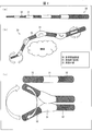
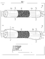
- FIG. 2 is a diagram showing an example of an internal structure of a multi-joint bending portion according to Embodiment 1, (a) to (b) are perspective views, and (c) and (d) are sectional views.
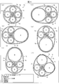
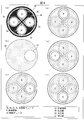
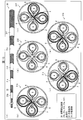
- (A)-(f) is sectional drawing which shows an example of the internal structure of the bending part of a multi joint bending part. It is sectional drawing which shows an example of the internal structure of the non-bending part of a multi joint bending part.
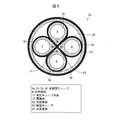
- FIG. 2 is a cross-sectional view of an articulated bending portion
- (a) is a cross-sectional view showing an example of a pressurizing portion
- (b) is a cross-sectional view of a pressurizing valve
- (c) to (f) are openings of the pressurizing valve.
- (b) is the state which bent Indicates.
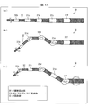
- (A)-(d) is sectional drawing of the articulated bending part which concerns on Embodiment 2.
- FIG. 1 is a perspective view which shows the bending operation
- FIG. FIG. 4 is a cross-sectional view of a multi-joint bending portion according to Embodiment 3 of the present invention, (a) is a cross-sectional view of a tip portion, and (b) to (c) are cross-sectional views showing an example of the configuration of an intermediate portion / terminal portion.
- FIGS. 7D to 7E are cross-sectional views showing other examples of the configuration of the intermediate part / terminal part.
- FIG. 7 is a cross-sectional view of a multi-joint bending portion according to Embodiment 4 of the present invention, (a) is a cross-sectional view of a tip portion, and (b) to (c) are cross-sections showing an example of the configuration of an intermediate portion / terminal portion.
- FIG. (A)-(b) is sectional drawing of the articulated bending part which concerns on Embodiment 5 of this invention. It is a perspective view which shows the bending operation
- (A)-(b) is sectional drawing which shows an example of a structure of the intermediate part / terminal part of the articulated bending part which concerns on Embodiment 6 of this invention.
- (A)-(f) is the perspective view and sectional drawing which show the specific example of a structure of the intermediate part / terminal part of the articulated bending part which concerns on Embodiment 6 of this invention. It is a perspective view which shows an example of the bending operation
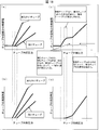
- (A) (b) is a graph which shows the case of a single elastic tube
- (c) (d) is a graph which shows the case where an elastic tube exists in an outer periphery.
- (A) is a state where the A tube is pressurized but not expanded
- (b) is a state where the A tube is expanded and pressure is applied to the outer tube
- (c) is a state where the outer tube is also expanded.
- (D) is sectional drawing which shows the state which expansion
- Embodiment 1 Hereinafter, embodiments of the present invention will be described in detail with reference to FIGS. 1 to 6, FIG. 18, and FIG.
- the bending device of the present invention is a medical device that can be attached to the tip.
- a multi-joint bending section 30 having a plurality of deformable bending sections 31 (joints) will be described.
- the bending apparatus according to the present invention also includes a bending apparatus having one joint. included.
- FIG. 1 is a diagram illustrating a configuration of an endoscope apparatus as an example of a medical device including an elastic tube according to an embodiment of the present invention.
- an endoscope apparatus 100 (medical device) includes an endoscope unit (medical device unit) 10 and a control device 20.
- the control device 20 drives and controls the endoscope unit 10. Details of the control device 20 will be described later.
- the endoscope unit 10 has a plurality of bent portions (joints) including a plurality of inflatable elastic tubes 1 having an elongated hollow cylindrical shape and enclosing air (gas) W.
- the multi-joint bending part 30 is composed of 31 and a plurality of non-bending parts 32, and the endoscope camera (medical instrument) 2 and the non-inflatable tube are fixed to the tip of the multi-joint bending part 30.
- FIG. 4 (a) is a cross-sectional view taken along the line A-A 'of FIG. 3 (a).
- FIG. 5 is a cross-sectional view taken along the line B-B ′ of FIG.
- the bent portion 31 includes four elastic tubes 1a, 1b, 1c, and 1d embedded with a flexible non-stretchable body 4 fixed in the long axis direction. And an elastic tube 1k (cylindrical member) having a hollow structure and holding these elastic tubes 1a to 1d therein.
- the non-bending portion 32 includes four non-expanding tubes 3a to 3d each having a non-expandable body 34 around the elastic tubes 1a to 1d, and these non-expanding tubes 3a to 3d. It consists of the rigid tube 33 which has. (Since the hollow portions of the elastic tube 1a and the non-expandable tube 3a communicate with each other, they are collectively referred to as an A tube. The same applies to the B tube and the like.)
- the elastic tubes 1a to 1d constituting the multi-joint bending portion have a structure in which a flexible non-stretchable body 4 fixed in the long axis direction is embedded between an inner peripheral surface and an outer peripheral surface.
- the elastic tubes 1a to 1d of the bent portions (joints) 31 in (b) to (e) of FIG. 4 show a state where each is expanded by the pressure of the air W (fluid) injected from the control device 20. ing. Thus, it can be bent in four directions by pressurizing each elastic tube. Further, as shown in FIG. 4F, if any two elastic tubes are selected, bending in the intermediate direction is possible. Furthermore, by sequentially applying pressure while adjusting the pressure to each elastic tube, a rotational motion as shown in FIG.
- FIG. 5 shows a cross-sectional configuration of the non-bent portion 32.
- the non-expandable tubes 3a to 3d have a structure in which a non-expandable body 34 is wound around the elastic tubes 1a to 1d. Further, the outermost periphery of the non-bent portion 32 is configured by a rigid tube 33. Therefore, by applying pressure to the elastic tubes 1a to 1d, the non-expandable tubes 3a to 3d are not expanded, and the bent portion 31 can be bent without bending the non-bent portion 32.
- the elastic tubes inside the non-expandable tubes 3a to 3d inside the rigid tube 33 already have a non-expandable body 34 around them. There is no. However, it is possible to form the bent portion 31 and the non-bent portion 32 only by the presence / absence of the non-expandable body 34 and the rigid tube 33 when the non-expandable body 4 is integrally molded in advance for manufacturing. The degree of freedom increases. Therefore, in the figure, all elastic tubes are described as structural examples having non-stretchable bodies 4.
- the elastic tube 1 has an elastic tube main body 11, a non-stretchable body 4, and a fixing portion 13 for fixing the non-stretchable body 4.
- the elastic tube main body 11 is a main member constituting the elastic tube 1, and the fixing portion 13 is provided in the major axis direction of the elastic tube 1, and enables the non-stretchable body 4 to be fixed.
- the non-stretchable body 4 may be configured to be fixed to the outer peripheral surface or inner peripheral surface of the elastic tube via the fixing portion 13, but here, as shown in FIG. A description will be given by taking an example of fixing in a state of being embedded between the peripheral surface and the outer peripheral surface (thick portion).
- the tip of the multi-joint bending portion 30 configured with the structure in which the four elastic tubes 1 are combined as a basic structure is sealed on the side where the endoscope camera 2 is fixed.
- a fixing portion for fixing the endoscope camera 2 is provided at the sealed tip of the multi-joint bending portion 30, and allows a medical instrument to be attached to the multi-joint bending portion 30.
- the medical instrument attached to the fixed part is not limited to the endoscope camera 2 and may be a catheter, a laser knife, an electric knife, or the like.
- the fixing portion and the fixing portion 13 are a part of the elastic tube 1 and are made of the same material as the elastic tube 1.
- the elastic tube body 11 has a uniform thickness, stress is particularly applied to the portion where the non-stretchable body 4 is fixed when pressurized, so that only that portion is likely to deteriorate. Therefore, as shown in FIG. 4 (a), when four elastic tubes 1 are structured, a space is generated between them, and the elastic tube of the portion to which the non-stretchable body 4 is fixed using this space.
- the thickness of the main body 11 can be made thicker than other portions where the non-stretchable body 4 is not fixed. As a result, the durability of the fixing portion 13 is improved, the non-stretchability is also increased, and there is an effect that it is possible to obtain a stable bending operation with no hysteresis with respect to pressurization.
- FIG. 6A is an example of a configuration of four relatively simple elastic tubes 1, and shows a cross section of the unbent portion 32 at the end of the multi-joint bent portion 30.
- a pressurizing part 35 for pressurizing the elastic tube 1 is provided at the end part of the articulated bending part 30 on the control device 20 side.
- the end portion has a structure in which only the inside of the non-expandable tubes 3a to 3d is opened, and the other portions are sealed.
- a medical instrument such as an endoscope camera is attached to the distal end, the power source and the signal cable are taken out from the side surface of the sealed portion, etc., which are omitted in this figure.
- FIG. 6B shows an example of the structure of the pressurizing valve 36
- FIGS. 6C to 6F show a configuration in which the pressurizing valve 36 is disposed in the pressurizing portion 35.
- FIG. 6B shows an example of the structure of the pressurizing valve 36
- FIGS. 6C to 6F show a configuration in which the pressurizing valve 36 is disposed in the pressurizing portion 35.
- FIG. 6B shows an example of the structure of the pressurizing valve 36
- FIGS. 6C to 6F show a configuration in which the pressurizing valve 36 is disposed in the pressurizing portion 35.
- a pressurizing valve 36 shown in FIG. 6 (b) is arranged in the pressurizing portion 35, and as shown in FIGS. 6 (c) to (f), by applying a rotational motion to the pressurizing valve 36, only the A tube is provided.
- a tube and B tube, B tube only, B tube and C tube, C tube only, C tube and D tube, D tube, etc. can be pressurized sequentially, according to the rotation of this pressurizing valve 36
- the rotating operation of the endoscope camera 2 attached to the tip as shown in (c) of 2 can be performed.
- the pressurizing valve 36 includes an opening 37.
- the A tube, the B tube, the C tube, and the D tube are supplied with air W from the control device 20 to be described later and are pressurized.
- the pressurizing valve 36 is rotated by the control of the control device 20, and the position of the opening 37 can be changed. Thereby, the tube which should be pressurized can be selected and the air W can be supplied to the said tube.
- the non-expansion tube 3 and the connection tube 5 until it connects to the pressurization control apparatus 20 It may be provided in the middle or at the connection portion. Since the movable mechanism of the valve is provided, it is desirable that the valve is installed as close to the control device 20 as possible and at the end that does not interfere with the operation.
- pressurizing parts there are two or more pressurizing parts as a pressurizing part for pressurizing the four tubes for driving the tip part and a pressurizing part for pressurizing the four tubes for driving the middle to terminal parts. Also good. Details will be described later as a sixth embodiment.
- each tube is provided with a pressurizing mechanism independently and controlled independently to perform precise position control that can be controlled at any position, not just rotation. It doesn't matter.
- FIG. 3A is a perspective view showing a main part of the multi-joint bending part 30 constituting the endoscope part 10 of the endoscope apparatus 100 in FIG. 4A is a cross-sectional view taken along the line AA ′ of the bent portion 31 of the endoscope unit 10 in FIG.
- the elastic tube 1 shown in FIG. 4 is made of, for example, a silicone (polydimethylsiloxane added with a reinforcing agent such as silicon oxide) tube having an outer diameter of 2 mm, an inner diameter of 1 mm, and a length of 5 mm.
- the elastic tube 1 is elastic from the control device 20 (see FIG. 1). It expands and contracts due to the pressure of the air W injected into the tube 1.
- the pressure of the air W enclosed in the elastic tube 1 is normal pressure (1 atm)
- the shape of the articulated bending portion 30 configured with the elastic tube 1 as a main part is as shown in FIG. As shown, it is linear.
- the elastic tube 1a (A tube) expands at the bent portion 31 as shown in FIG. .
- an LED lamp for illumination (not shown) can be attached adjacent to the fixed portion to which the endoscope camera 2 is attached.
- illustration of a fixing part is abbreviate
- the non-stretchable body 4 functions to prevent (suppress) expansion of the elastic tube 1. That is, due to the pressure increase of the air W enclosed in the elastic tube 1, the elastic tube 1 is opposite to the fixed portion where the non-stretchable body 4 is embedded and fixed (in the elastic tube 1k in FIG. 3A). Even if the upper side expands, it does not expand on the fixed part side. Therefore, as shown in FIG. 3B, the multi-joint bending portion 30 can be bent downward (opposite to the expansion portion P) in the drawing. For this reason, the bending angle of the multi-joint bending part 30 can be arbitrarily changed by changing the pressure of the air W in the elastic tube 1a.
- FIG. 18A is a graph showing the relationship between the internal pressure and the cross-sectional area of the hollow portion of the elastic tube when a basic elastic tube is pressurized.
- FIG. 18A is a graph showing the relationship between the internal pressure and the bending angle. This is shown in FIG.
- FIG. 18 (a) when the elastic tube is pressurized, the elastic tube initially has tension, so it does not expand with pressure, but when the internal pressure exceeds this tension, the elastic tube does not expand.
- the cross-sectional area increases, bending begins. This bending motion depends on the thickness of the elastic tube and the elastic modulus of the material. For example, as shown in FIGS.
- a soft tube starts bending from a low pressure and bends greatly
- a hard tube starts bending from a relatively high pressure and bends relatively small. Therefore, the bending operation characteristics can be arbitrarily set according to the structure of the elastic tube or the design of the material.
- FIGS. 18C is a graph showing the relationship between the internal pressure of the A tube and the cross-sectional area of the hollow portion of the A tube.
- FIG. 18D shows the relationship between the internal pressure of the A tube and the bending angle of the elastic tube 1k. It is a graph to show.
- the A tube is gradually pressurized, and when the pressure from the elastic tube 1a is applied to the elastic tube 1k, the expansion of the A tube is temporarily suppressed.
- the relationship between the internal pressure of the A tube and the cross-sectional area of the hollow portion is a stepwise increase in cross-sectional area.
- the relationship between the internal pressure of the A tube and the bending angle is a stepwise bending operation as shown in FIG. That is, the bending angle of the elastic tube 1k changes stepwise according to the increase in pressure inside the A tube. Since this bending operation depends not only on the elastic tube 1a but also on the size and thickness of the elastic tube 1k and the elastic modulus of the material, the bending operation characteristics are arbitrarily set according to the structure and material design. be able to.
- stepwise bending operation of the elastic tube 1k as described above is realized not only when the pressure inside the A tube increases but also when the pressure decreases (decreases).
- the elastic tube 1k on the outer periphery in this way suppresses expansion in the circumferential direction (lateral direction) of the elastic tube that does not contribute to bending, and expands in the long axis direction (vertical direction) that directly affects the control of the bending angle. It is possible to produce a special effect such that the bending can be effectively performed. Further, since unnecessary expansion in the circumferential direction of the elastic tube is suppressed, deterioration of the elastic tube due to mechanical stress caused by repeated expansion and contraction can be prevented.
- the air pressure W at the time of non-bending is preferably set to a pressure immediately before the elastic tube starts to bend. Thereby, the bending by the dead weight of an elastic tube can be prevented, and an elastic tube can be hold
- the stretchability of the non-stretchable body 4 only needs to be lower than that of the elastic tube main body 11. It is sufficient that the elastic tube body 11 is not expanded on the fixing portion 13 side.
- a non-stretchable thread fishing line
- silicone of the same material as the elastic tube 1 may be used.
- the non-stretchable body 4 may be shared with a cable connected to a medical instrument.
- the non-stretchable body 4 shown in FIG. 4A may also be used as an electric cord that supplies power to the endoscope camera 2.
- the non-stretchable body 4 can also be used as a cable for connecting the endoscope camera 2 and a camera monitor (not shown) along the endoscope unit 10 shown in FIG.
- the cable connected to the non-stretchable body 4 and the medical instrument can be fixed inside the elastic tube body 11.
- the non-expandable tube 3 has the same shape as the articulated bending portion 30, that is, about 2 cm to 30 cm in length having the same outer diameter and inner diameter as the elastic tube body 11 (not limited to this). It is desirable that the length is appropriately set depending on the number of joints), and can be made of an acrylic resin.
- connection tube 5 is a tube that connects the endoscope unit 10 and the control device 20.
- the connection tube 5 is a flexible and non-expandable hollow cylindrical tube connected to the non-expandable tube 3.
- the connection tube 5 has substantially the same shape and length as the non-expanding tube 3 and is about 2 m in length.
- the connection tube 5 communicates with the elastic tube 1 and the non-expanding tube 3 and is filled with air W.
- connection tube 5 may be composed of a plurality of connection tubes according to the structure of the pressurizing mechanism for the elastic tube.
- FIG. 3C is a diagram showing a cross section in the major axis direction of the elastic tube 1a and the non-expandable tube 3a, taking the elastic tube 1a as an example, and is taken along line CC ′ in FIG. It is sectional drawing.
- the non-expandable tube 3 a has a configuration in which the periphery of the elastic tube 1 a is wound with a non-expandable body 34.
- FIG. 3 is another example of the structure of the elastic tube 1a and the non-expandable tube 3a.
- the elastic tube 1a and the non-expandable tube 3a are separate members from each other, and may be integrated by adhesion, and the hollow portion may be communicated.
- the hollow portions of the elastic tube 1a and the non-expandable tube 3a communicate with each other, they are collectively referred to as the A tube.
- the B tube and the like the air W is enclosed in the elastic tube 1a and the like through the non-expanding tube 3 from the connection tube 5 side.
- the non-stretchable body 4 is very thin compared to the elastic tube main body 11.
- the outer diameter of the cross section of the elastic tube main body 11 is 2 mm
- the outer diameter of the cross section of the non-stretchable body 4 is 0.3.
- the cross section of the non-stretchable body 4 is not limited to a circular shape, and has a chamfered corner so as not to damage the human body when inserted into the body.
- a polygonal shape such as a triangle or a rectangle may be used.
- the elastic tube 1 may have a configuration in which a fixing portion 13 (not shown) is disposed on the outer peripheral surface (outside) of the elastic tube main body 11. In this case, the non-stretchable body 4 is fixed to the outside of the elastic tube body 11.
- the non-stretchable body 4 (electric cord) is not only the fixing portion 13 in the elastic tube 1 but also the non-expandable tube 3 (see FIG. 1) and is led out of the endoscope unit 10.
- the elastic tube may be configured such that the fixing portion is disposed on the inner peripheral surface (inner side) of the elastic tube main body 11.
- the non-stretchable body 4 is fixed inside the elastic tube body 11.
- the non-stretchable body 4 may also be used as a cable connected to a medical instrument.
- the cable connected to the non-stretchable body 4 and the medical instrument is fixed to the inside of the elastic tube main body 11, so that the surface of the elastic tube main body 11 is exposed even when the elastic tube is exposed to the outermost periphery. There are no irregularities on the surface. For this reason, the elastic tube 1m can be easily cleaned and disinfected, and can be easily reused.
- the cable connected to the non-stretchable body 4 and the medical instrument is fixed to the inside of the elastic tube body 11, so that the arrangement is protected by the elastic tube body 11.
- the damaged portion is protected by the elastic tube main body 11, so that the human body is less likely to be damaged.
- the human body may be damaged due to the damaged portion of the non-stretchable body 4. Low.
- the cable connected to the medical instrument is an electrical cable
- adverse effects such as leakage due to the breakage of the electrical cable can be avoided in the human body.
- poured in the elastic tube main body 11 even if an electric cable is damaged, since electricity is hard to be conducted in the elastic tube main body 11, the bad influence of a leakage can be avoided in the elastic tube main body 11. .
- the cable connected to the medical instrument may be arranged inside the hollow of the elastic tube main body 11.
- the fixing portion is disposed on the inner peripheral surface (inner side) of the elastic tube body 11
- the non-stretchable body 4 different from the cable connected to the medical instrument is fixed to the inner side of the elastic tube body 11
- the cable 14 connected to the instrument may be arranged inside the hollow of the elastic tube body 11.
- the elastic tube may be configured such that the fixing portion is disposed inside the elastic body in the elastic tube main body 11.
- the elastic body constitutes the elastic tube main body 11 and is a thickness portion from the inner peripheral surface to the outer peripheral surface of the elastic tube main body 11. If it demonstrates more concretely, an elastic tube is the structure by which an adhering part is arrange
- the non-stretchable body 4 may also be used with the cable 14 connected to the medical instrument.
- the non-stretchable body 4 When the non-stretchable body 4 is not used as a cable connected to a medical instrument, the non-stretchable body 4 is fixed in a state of being embedded between the inner peripheral surface and the outer peripheral surface of the elastic tube body 11 and the cable 14 May be disposed inside the hollow of the elastic tube body 11.
- the non-stretchable body 4 or the cable 14 may be configured to be in contact with the outer peripheral surface and the inner peripheral surface of the elastic tube main body 11, but in order to increase the mechanical strength of the elastic tube, the outer peripheral surface of the elastic tube main body 11 It is desirable that it is arranged with a space between the inner peripheral surface.
- the cable connected to the non-stretchable body 4 and the medical instrument is embedded between the inner peripheral surface and the outer peripheral surface of the elastic tube main body 11, so that it is formed on the surface (outer peripheral surface) of the elastic tube main body 11. Unevenness does not occur. For this reason, even when the elastic tube is exposed on the outermost periphery, the elastic tube can be easily cleaned and disinfected, and can be easily reused.
- the cable connected to the non-expandable body 4 and the medical device is fixed between the inner peripheral surface and outer peripheral surface in the elastic tube main body 11, or the hollow inside of the elastic tube main body 11. Therefore, the arrangement is protected by the elastic tube body 11. For this reason, when a part of the cable connected to the non-stretchable body 4 and the medical instrument is damaged for some reason, the damaged portion is protected by the elastic tube main body 11, so that the human body is less likely to be damaged.
- the human body may be damaged due to the damaged portion of the non-stretchable body 4.
- the cable connected to the medical instrument is an electrical cable
- adverse effects such as leakage due to the breakage of the electrical cable can be avoided in the human body.
- poured in the elastic tube main body 11 even if an electric cable is damaged, since electricity is hard to be conducted in the elastic tube main body 11, the bad influence of a leakage can be avoided in the elastic tube main body 11. .
- the entire outer peripheral surface of the cable connected to the non-stretchable body 4 or the medical instrument is fixed to the elastic tube body 11. For this reason, the bending angle ⁇ of the elastic tube changes at a constant rate corresponding to the pressure P of the air inside the hollow of the elastic tube main body 11. Therefore, there is an advantage that the bending angle ⁇ of the elastic tube body 11 can be easily controlled.
- the above-described adverse effects on the human body due to the cable 14 connected to the medical instrument can be avoided. Moreover, since the vicinity of the medical instrument fixed to the elastic tube 1 can be made compact, the cable connected to the medical instrument does not interfere with the medical procedure.
- the control device 20 will be described with reference to FIG. The following description is an example of the control device 20, and does not limit the configuration of the control device.
- the control device 20 only needs to be able to pressurize the tube included in the multi-joint bending portion 30, and is not limited to the following configuration, and can have various configurations.
- the control device 20 includes a piston (atmospheric pressure variable portion, fluid pressure variable portion) 21 and a syringe 22 that change the pressure of air (gas) W in the elastic tube 1, an air pressure sensor 23 that detects the pressure of the air W, and a piston.
- 21 is provided with a piston drive part (atmospheric pressure variable part) 24 that operates the inside of the syringe 22 and varies the air pressure in the elastic tube 1, and a pressurization control part (atmospheric pressure variable part) 26 that controls the piston drive part 24.
- the pressurization control unit (atmospheric pressure varying unit) 26 is, for example, a microphone (instruction receiving unit) 25 for inputting an operator's voice (instruction), an audio signal input from the microphone 25, and a detection signal of the air pressure sensor 23.
- the structure which inputs and controls the piston drive part 24 may be sufficient.
- the gas sealed in the elastic tube 1 is not limited to air, and any gas may be used as long as it does not contaminate the medical treatment site.
- control device 20 includes a pressurizing valve driving unit 28.
- the pressurization valve drive unit 28 rotates the pressurization valve 36 in accordance with the control of the pressurization control unit 26.
- the piston 21, the piston drive unit 24, and the pressurization control unit 26 are used as an example of the atmospheric pressure variable unit, but an atmospheric pressure adjustment valve or the like may be used instead. Further, a foot switch or the like may be used instead of the microphone.
- the piston drive unit 24 is controlled by the pressurization control unit 26 based on the voice of the surgeon detected by the microphone, and the air pressure in the elastic tube 1 is changed using the piston 21 and the syringe 22.
- the endoscope camera 2 can be bent upward or downward on the display screen of the camera monitor
- the surgeon speaks “up” the display screen of the camera monitor Start moving to show direction. Then, the movement of the display screen on the camera monitor is stopped by the voice “stop” by the surgeon.
- the voice by the surgeon is “down”, the display screen on the camera monitor moves downward in the displayed image.
- the elastic tube 1 used in medical treatment or the like can be replaced with a new elastic tube 1 (disposable). Alternatively, after the medical treatment is completed, the used elastic tube 1 can be reused (reused) by cleaning and disinfecting it.
- the elastic tube 1 is reused, in order to prevent the use of the deteriorated elastic tube 1, the upper limit number of times of use or the upper limit number of bending of the elastic tube 1 is set in advance in the control device 20, The elastic tube 1 exceeding the number of times needs to be unusable.
- the piston 21 is slidably inserted into the syringe 22 connected to the connection tube 5.
- the piston 21 is screwed into a screw part connected to the piston driving part 24, and the piston driving part 24 slides the piston 21 in the syringe 22 by rotating the screw part forward or backward. It may be.
- the pressure controller 26 controls the forward or reverse rotation of the piston drive unit 24 and the number of rotations thereof.
- the bending angle ⁇ of the elastic tube 1 gradually increases monotonously as the air pressure increases up to the pressure of 230 kPa.
- the pressure P passes around 230 kPa
- the bending angle ⁇ of the elastic tube 1 increases rapidly as the pressure P increases.
- the pressure P of the air W in the elastic tube main body 11 is decreased (during depressurization)
- the bending angle ⁇ of the elastic tube 1 corresponds to the decrease in the pressure P until the pressure P reaches 230 kPa. Slowly and monotonously decrease.
- the bending angle ⁇ of the elastic tube body 11 rapidly decreases as the pressure P decreases until the pressure P reaches 170 kPa.
- the bending angle ⁇ of the elastic tube body 11 gradually decreases monotonously according to the decrease in the pressure P.
- the elastic tube main body 11 is bent so that the display image displayed on the camera monitor moves at a constant rate. The angle can be changed.
- the bending angle ⁇ of the elastic tube 1b is approximately linear with an increase in air pressure from a pressure of about 100 kPa to about 260 kPa. To increase. Further, when the pressure P of the air W in the elastic tube main body 11 is decreased (during pressure reduction), the bending angle ⁇ of the elastic tube 1b corresponds to the decrease in the pressure P until the pressure P is in the vicinity of 260 kPa to 100 kPa. Decreases linearly.
- the bending angle ⁇ of the elastic tube 1b changes at a constant rate, and a large hysteresis characteristic does not occur. Further, the relationship between the pressure P and the angle ⁇ during pressurization is substantially equal to the relationship between the pressure P and the angle ⁇ during decompression.
- the elastic tube main body 11 is bent so that the display image displayed on the camera monitor moves at a constant rate.
- the angle can be changed.
- the elastic tube body 11 has a linear bending characteristic
- the setting of the pressurization control unit 26 is an elastic tube having a hysteresis characteristic. This is simpler than when 1 is used. For this reason, there exists an advantage that the bending angle of the elastic tube main body 11 is easy to control.
- the elastic tube 1 may be configured to be automatically operated.
- the endoscope camera 2 shown in FIG. 1 when the endoscope camera 2 shown in FIG. 1 is used as a medical instrument, an image photographed by the endoscope camera 2 is displayed on the camera monitor at the same time, and at the same time, an image photographed by the endoscope camera 2 is displayed on the control device. 20 may be configured to acquire and analyze (not shown).
- the control device 20 automatically adjusts the pressure of the gas sealed in the elastic tube body 11 according to the analyzed information. Therefore, the bending angle of the endoscope camera 2 can be automatically changed. It is assumed that the control device 20 stores in advance image data indicating the progress of the medical procedure. Further, the control device 20 may change the bending angle of the endoscopic camera 2 using the hysteresis characteristic described above.
- the elastic tube 1 may be manually operated using a tablet terminal.
- a surgeon's assistant performing a medical procedure operates the tablet terminal to change the bending angle of the medical device
- the assistant can operate the tablet terminal at a position away from the surgeon. For this reason, the operation of the assistant does not interfere with the medical treatment action of the surgeon, and the surgeon can concentrate on the medical treatment.
- the surgeon may operate the tablet terminal to change the bending angle of the medical device. In this case, the robot can be made to perform an actual medical procedure instead of the operator.
- Embodiment 1 the movable mechanism having mainly one bent portion has been described in detail, but in Embodiment 2, a movable mechanism that operates in combination with two bent portions will be described.
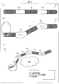
- FIG. 7 shows an example of a movable mechanism that operates in combination with two bent portions combined.
- the configuration having the four elastic tubes 1a to 1d constituting the multi-joint bending portion is the same as that of the first embodiment, but the positions of the elastic tubes 1a to 1d at the non-bending portion 32 are as shown in FIG. It replaces with the opposite side.
- FIG. 8A is a cross-sectional view taken along the line DD ′ of FIG. 7A
- FIG. 8B is a cross-sectional view taken along the line EE ′ of FIG. 8C
- FIG. 8D is a cross-sectional view taken along the line GG ′ in FIG. 7B.
- FIG. 8A is a cross-sectional view taken along the line DD ′ of FIG. 7A
- FIG. 8D is a cross-sectional view taken along the line GG ′ in FIG. 7B.
- the elastic tube 1a can be replaced with 1c, and 1b can be replaced with 1d.
- This is a unique configuration possible because it is an independent elastic tube.
- the bending angles of the two bent portions are set to be the same, unlike the first embodiment, it can be moved without changing the direction of the tip portion.
- the visual field can be moved without changing the visual field angle, so that a special effect of obtaining an image that is very easy for the operator to obtain can be obtained.
- the bending operation of the two bent portions 31a and 31b depends not only on the elastic tube 1a but also on the size and thickness of the elastic tube 1k, the elastic modulus of the material, and the weight of the supporting tube. Therefore, the bending operation characteristics can be set to the same according to the design of these structures and materials.
- the elastic tube 1k on the outer periphery in this way suppresses expansion in the circumferential direction (lateral direction) of the elastic tube that does not contribute to bending, and expands in the long axis direction (vertical direction) that directly affects the control of the bending angle. It is possible to produce a special effect such that the bending can be effectively performed. Further, since unnecessary expansion in the circumferential direction of the elastic tube is suppressed, deterioration of the elastic tube due to mechanical stress caused by repeated expansion and contraction can be prevented.
- each elastic tube can be bent in four directions by pressurizing, and if any two elastic tubes are selected, bending in the intermediate direction is also possible. That is, by sequentially applying pressure while adjusting the pressure applied to each elastic tube, it is possible to rotate the tip as shown in FIG. 9B and to move the visual field in any direction.
- one set of bent portions 31 bends in a specific direction depending on the position of the tube incorporated in advance. For example, if the positions of the elastic tubes 1a to 1d are exchanged with the opposite side at the non-bending portion 32 as described above, the bending in the reverse direction can be obtained. Can do.
- the pressure for starting the bending may be adjusted by appropriately combining the various structures described above, and the bending operation of each bent portion may be performed simultaneously. You may comprise so that it may bend in order from this bending location.
- the movable mechanism having one or two bent portions has been described in detail with respect to a case where the movable mechanism is used, particularly in the tip portion to which the camera is attached.
- a movable mechanism that operates by combining many bent portions will be described.
- the distal end portion to which the camera is attached uses the movable mechanism that operates by combining one or two bent portions described in the first embodiment and the second embodiment, and the second embodiment is used in the middle portion and the end portion.
- bent portion 31a on the distal end side is shown in FIG. 10A, but since it has already been described in the first and second embodiments, a detailed description thereof will be omitted.
- the cross-sectional structure of the bent part 31b on the intermediate part side and the terminal part side is shown in FIG.
- the elastic tubes 1a to 1d used for the distal end portion have a structure in which a non-expandable body 34 is wound around the inside of the bent portion 31b. Therefore, by pressing the elastic tubes 1a to 1d, the bent portion 31a can be bent without bending the bent portion 31b.
- 10 (d) and 10 (e) are cross-sectional views showing another example of the configuration of the bent part 31b on the intermediate part side and the terminal part side.
- FIGS. 10 (d) and 10 (e) show that it is desirable to wind the non-expandable body 34.
- elastic tubes 1e to 1h are arranged around the elastic tubes 1a to 1d for bending control at the intermediate part and the terminal part.
- the bending of the elastic tubes 1e to 1h is as described above.
- the elastic tube 1e is pressurized and expanded to perform a bending operation.
- the bending part 31a and the bending part 31b can be bent-controlled independently of each other.
- the distal end portion to which the camera is attached uses a movable mechanism that operates by combining one or two bent portions described in the first and second embodiments, and is used for controlling the intermediate portion and the end portion.
- the example of the structure which has a bending part using two elastic tubes is shown.
- bent portion 31a on the distal end side is shown in FIG. 11A, but since it has already been described in the first and second embodiments, a detailed description thereof will be omitted.
- the cross-sectional structure of the bent part 31b on the intermediate part side and the terminal part side is shown in FIG.
- the elastic tubes 1a to 1d used for the distal end portion have a structure in which a non-expandable body 34 is wound around the inside of the bent portion 31b. Therefore, by pressing the elastic tubes 1a to 1d, the bent portion 31a can be bent without bending the bent portion 31b.
- the elastic tube 1a is similar to FIGS. 10 (d) and 10 (e). It is desirable to wind a non-expandable body 34 around each of ⁇ 1d.
- an elastic tube 1i is arranged next to the elastic tubes 1a to 1d for bending control at the intermediate part and the terminal part.
- the bending of the elastic tube 1i is as described above, and the bending operation is performed by pressurizing and expanding the elastic tube 1i as shown in FIG. 11 (c).
- the bending part 31a and the bending part 31b can be bent-controlled independently of each other.
- the position of the elastic tube 1i is determined by the bent portion 31, bending in a certain direction can be obtained, and if the position is moved by another bent portion, bending in an arbitrary direction can be obtained. it can.
- the elastic tube incorporated in advance, it is possible to obtain an operation that avoids the set organ and a bending operation that turns around and looks into from the back side. Since the structure is simple, there are few other tubes used as a load, and a stable bending operation can be obtained.
- the distal end portion to which the camera is attached uses a movable mechanism that operates by combining one or two bent portions described in the first and second embodiments, and is used for controlling the intermediate portion and the end portion.
- the other modification of the structure which has a bending part using two elastic tubes is shown.
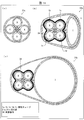
- FIG. 12 shows a cross-sectional configuration of the bent part 31b on the intermediate part side and the terminal part side.
- the elastic tube 1j is used for bending control at the intermediate part and the terminal part, but the elastic tubes 1a to 1d used at the tip part are arranged in this hollow interior.
- the elastic tube 1j has a structure in which the non-stretchable body 4 is embedded between the inner peripheral surface and the outer peripheral surface.
- the elastic tubes 1a to 1d used at the distal end have a structure in which a non-expandable body 34 is wound around.
- the elastic tube 1a is similar to FIGS. 10 (d) and 10 (e). It is desirable to wind a non-expandable body 34 around each of ⁇ 1d.
- the bending of the elastic tube 1j is as described above, and the bending operation is performed by pressurizing and expanding the elastic tube 1j as shown in FIG.
- the position of the non-stretchable body 4 of the elastic tube 1j is determined by the bent portion 31, a certain direction of bending can be obtained, and if the position of the non-stretchable body 4 is moved by another bent portion, Bending in any direction can be obtained.
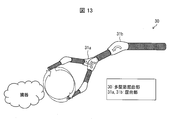
- FIG. 13 shows an example in which this structure is applied to the front end and the middle where the camera is attached.
- the elastic tube 1j is pressurized to bend the bent portion 31b, thereby defining the rough direction of the camera tip, and the visual field is moved by bending the bent portion 31a on the tip side in the configuration described in the second embodiment. Do. Since the viewing angle does not change, it is possible to move the field of view without a sense of incongruity.
- the number of elastic tubes to be bundled is reduced, so that the cross-sectional shape of the articulated bending portion becomes nearly circular, and the surface unevenness is reduced. For this reason, the elastic tube 1a can be easily cleaned and disinfected, and can be easily reused.
- the cable connected to the non-expandable body 4 and the medical device can be arrange
- the human body may be damaged due to the damaged portion of the non-stretchable body 4. Is low.
- the cable connected to the medical instrument is an electrical cable
- adverse effects such as leakage due to the breakage of the electrical cable can be avoided in the human body.
- poured in the elastic tube main body 11 even if an electric cable is damaged, since electricity is hard to be conducted in the elastic tube main body 11, the bad influence of a leakage can be avoided in the elastic tube main body 11. .
- an example is shown in which one elastic tube is used for controlling the intermediate portion and the end portion, and the elastic tube at the distal end portion is disposed inside the hollow of the elastic tube.
- An example is shown in which four elastic tubes are used for controlling the end portion, and one elastic tube at the tip portion is disposed inside the hollow of each elastic tube.
- the distal end portion to which the camera is attached uses a movable mechanism that operates by combining one or two bent portions described in the first and second embodiments, and 4 for controlling the intermediate portion and the end portion.
- the other modification of the structure which has a bending part using two elastic tubes is shown.
- FIG. 14 shows a cross-sectional configuration of the bent part 31b on the intermediate part side and the terminal part side.
- the elastic tubes 1e to 1h (first elastic tubes) are used for bending control at the intermediate portion and the end portion, and the elastic tubes 1a to 1d (second elastic tubes) used at the tip portions are respectively elastic tubes 1e. It is configured to be arranged in a hollow interior of ⁇ 1h.
- the bending of the elastic tubes 1e to 1h is as described above, and the bending operation is performed by pressurizing and expanding the elastic tubes 1e to 1h.
- the elastic tube 1e is pressurized by the bent portion 31, a certain direction of bending can be obtained, and the position of the elastic tube 1e can be moved by another bent portion. By doing so, it is possible to obtain bending in an arbitrary direction.
- the position of the elastic tube incorporated in advance it is possible to obtain an operation that avoids the set organ and a bending operation that turns around and looks into from the back side. Since the structure is simple, there are few other tubes to be a load, and a stable bending operation can be obtained.
- pressurizing unit for pressurizing the four tubes A to D for driving the bent portion at the distal end and the pressurizing unit for pressing the four tubes E to H for driving the bent portion at the middle to the end portions
- FIG. 15 shows a specific example in which this structure is applied to the intermediate part and the terminal part.
- FIG. 15A shows a configuration example having five bent portions 31b to 31f using four elastic tubes.
- the tip is not shown, and only the A tube to D tube used for the tip are shown in the cross-sectional portions shown in FIGS. 15 (b) to 15 (f). Since the configuration of the tip has already been described in the first and second embodiments, a detailed description thereof will be omitted.
- the cross-sectional structure of the bent portion is the structure shown in FIGS. 15B, 15C, 15D, 15E, and 15F sequentially from the side close to the tip.
- the first bent portion 31b, the second bent portion 31c, the third bent portion 31d, the fourth bent portion 31e, and the fifth bent portion 31f will be referred to in order.
- the first bent portion 31b has a structure in which the E and F tubes are wrapped with a non-expandable body 34, and does not expand even when pressed, that is, does not bend.
- the F and G tubes are wrapped with the non-expandable body 34
- the third bent portion 31d of FIG. There is no structure that is wrapped with the non-expandable body 34
- the fourth bent portion 31e in FIG. 15 (e) has a structure in which the G and H tubes are wrapped with the non-expandable body 34, and the fifth bent portion 31f in FIG. 15 (f). Then, it is set as the structure which wraps the E and H tubes with the non-expandable body 34.
- each tube is partially replaced at the non-bent portion 32, and there is no replacement at the non-bent portion 32 between (b) and (c) in FIG. 15, but (c) in FIG. 15 and (d), the F tube and the H tube are exchanged.
- the non-bending portion 32 between (d) and (e) of FIG. 15 the E tube and the G tube are exchanged.
- the F tube and the H tube are replaced again.
- the bending operation of the intermediate part and the terminal part is performed by pressurizing and expanding the E tube to the H tube.
- the position movement function of the avoidance joint shown in FIG. The avoidance joint interval changing function shown can be provided.
- FIG. 16B is a diagram showing a bent state when pressure is applied. Since the E tube has a structure in which the first bent portion 31b and the fifth bent portion 31f are wrapped with the non-expandable body 34, the E tube does not bend even when pressurized. Moreover, since the position is replaced by the non-bending portion 32 between the third bending portion 31d and the fourth bending portion 31e, bending in the reverse direction occurs before and after that. That is, the bent state shown in FIG.
- the other three tubes can be bent on the same principle, respectively.
- the state is as shown in FIG. 16 (a)
- the F tube is pressurized
- the state shown in FIG. If the G tube is pressurized in the state of), the state of FIG.
- the G tube is gradually pressurized, and at the same time, the entire tube may be rotated 180 degrees.
- Such complex movements can be realized with a simple structure with only the mechanism for pressurizing the eight elastic tubes and rotating and inserting / removing the entire tube, and the application range can be expanded to relatively complicated operations.
- the non-stretchable body 4 can also be used as a cord for sending air to the catheter. Air sent to the catheter inflates the balloon of the catheter.
- the catheter may be a guide wire type.
- the articulated bending part 30 is used instead of the guide wire for guiding the direction in which the catheter advances. That is, a catheter is connected to the non-expandable tube 3 without the articulated bend 30, and the articulated bend 30 (opposite to the fixed portion) is connected to the other end of the catheter on the opposite side of the non-expandable tube 3. Side end) is connected. It is assumed that the gas sealed in the elastic tube 1 in the articulated bending portion 30 is injected from the non-expandable tube 3 through a catheter. Thereby, by adjusting the pressure of the gas sealed in the elastic tube main body 11, the articulated bending part 30 can guide the direction in which the catheter advances.
- the non-stretchable body 4 can be used also as a cord for sending a signal for controlling the laser emitted from the laser knife.
- the medical instrument attached to the elastic tube 1 may be an electric knife.
- the present invention can also be expressed as follows.
- the endoscope apparatus has a flexible non-stretchable body fixed in the length direction to the elastic tube portion, has an elongated hollow cylindrical shape, and has a distal end portion sealed and fluid.
- a multi-joint bending apparatus comprising a plurality of inflatable elastic tubes enclosed, a camera fixed to the tip thereof, and a hollow cylinder that is connected to the other end of the plurality of elastic tube portions and encloses a fluid
- a non-expandable tube having a shape, a flexible and non-expandable hollow cylindrical connection tube connected to the non-expandable tube portion, and the elastic tube through the connection tube and the non-expandable tube.
- a control unit that variably controls the fluid pressure, and the control unit controls the fluid pressure in the elastic tube, and the fluid pressure causes the elastic tube to expand and contract on the opposite side of the non-stretchable body. , Thereby also expressed as an endoscope apparatus for bending the articulated bending apparatus to an arbitrary angle.
- the control unit changes a fluid pressure in the elastic tube, and a fluid pressure sensor detects the fluid pressure.
- a piston drive unit that operates the piston in the syringe and varies a fluid pressure, a microphone that inputs an operator's voice, a voice signal input by the microphone, and a detection signal of the fluid pressure sensor.
- a pressure control unit that inputs and controls the piston drive unit, and controls the piston drive unit by the pressurization control unit and changes the fluid pressure in the elastic tube by an operator's voice It may be.
- the non-stretchable body may be made of a polyamide fiber in the endoscope apparatus having the above configuration.
- the endoscope apparatus according to the present invention may be an electric cord in which the non-stretchable body supplies power to the camera in the endoscope apparatus having the above configuration.
- the articulated bending device (40) includes a fixing portion (12) to which a medical instrument (endoscopic camera 2, catheter 2a, laser knife 2c) can be attached at the tip, and the tip is sealed,
- An elastic tube main body (11) having an elongated hollow cylindrical shape, and a fixing portion (13) to which a non-stretchable body (4) having flexibility can be fixed in the longitudinal direction of the elastic tube main body, By controlling the pressure of the fluid injected into the elastic tube main body, the elastic tube main body (11) can be expanded or contracted on the opposite side of the non-stretchable body.
- a medical device endoscopic device 100
- it is characterized in that it is arranged inside the hollow of the bending device.
- the convenience in the medical field is remarkably superior in that it is disposable and does not invade the human body. It is expected to spread widely.
- the articulated bending device (40) according to aspect 2 of the present invention is the above-described aspect 1, wherein the fixing portion includes the non-stretchable body made of a material having lower elasticity than the elastic tube main body. It may be fixed.
- the non-stretchable body made of a material having lower elasticity than the elastic tube main body is fixed to the elastic tube main body.
- the non-stretchable body of the silicone material is easily fixed to the elastic tube body.
- a polyamide fiber is used for the non-stretchable body, it is difficult to adhere to an elastic tube made of a silicone material. Therefore, this is effective when the non-stretchable body is easily removed from the elastic tube.
- the fixing portion may be disposed between an inner peripheral surface and an outer peripheral surface of the elastic tube body.
- the entire outer peripheral surface of the cable connected to the non-stretchable body or the medical instrument is fixed to the elastic tube body. For this reason, the bending angle of the elastic tube changes at a constant rate corresponding to the pressure of the fluid P inside the hollow of the elastic tube main body. Therefore, there is an advantage that it is easy to control the bending angle of the elastic tube body.
- the multi-joint bending device (40) according to the fourth aspect of the present invention is the multi-joint bending device (40) according to any one of the first to third aspects, wherein a plurality of the elastic tubes arranged in the hollow interior of the multi-joint bending device in the non-bent portion. The arrangement position may be changed.
- the tube on the opposite side can be bent in the opposite direction at two adjacent bent portions, so when used for the tip portion, it can be moved without changing the direction of the tip portion. it can.
- the visual field can be moved without changing the visual field angle, so that a special effect of obtaining an image that is very easy for the operator to obtain can be obtained.
- the multi-joint bending device (40) according to the fifth aspect of the present invention is the multi-joint bending device (40) according to any one of the first to fourth aspects, wherein the elastic tube for bending the tip of the multi-joint bending device includes an intermediate portion and You may arrange
- the number of elastic tubes to be bundled is reduced, so that the cross-sectional shape of the articulated bending portion becomes nearly circular, and the surface unevenness is reduced. For this reason, the elastic tube 1a can be easily cleaned and disinfected, and can be easily reused.
- the articulated bending device (40) according to aspect 6 of the present invention is the elastic tube body according to any one of the aspects 1 to 5, wherein the elastic tube body is a hollow cable in the elastic tube body. It may be arranged inside.
- the cable connected to the non-stretchable body 4 and the medical device can be disposed further inside the elastic tube disposed in the hollow interior, and thus the arrangement protected by the elastic tube multiple times. Is possible. For this reason, when a part of the cable connected to the non-stretchable body 4 and the medical instrument is damaged for some reason, the damaged portion is protected several times by a plurality of elastic tubes, and thus the human body is less likely to be damaged. Become. For example, when a part of the non-stretchable body 4 is damaged for some reason, even if the non-stretchable body 4 is less stretchable than the elastic tube 1a, the human body may be damaged due to the damaged portion of the non-stretchable body 4.
- the cable connected to the medical instrument is an electrical cable
- adverse effects such as leakage due to the breakage of the electrical cable can be avoided in the human body.
- poured in the elastic tube main body 11 even if an electric cable is damaged, since electricity is hard to be conducted in the elastic tube main body 11, the bad influence of a leakage can be avoided in the elastic tube main body 11. .
- the cable connected to the said medical instrument Is disposed inside the hollow of the elastic tube body 11. For this reason, the adverse effect on the human body described above due to the cable connected to the medical device can be avoided. Moreover, since the vicinity of the medical instrument fixed to the elastic tube 1 can be made compact, the cable connected to the medical instrument does not interfere with the medical procedure.
- a control device (20) according to aspect 7 of the present invention is a control device that controls expansion and contraction of the elastic tube according to aspect 1, and includes an instruction receiving unit (microphone) that receives an instruction to expand or contract the elastic tube. 25) and the fluid pressure variable section (piston 21, piston drive section 24, pressure control) that varies the pressure of the fluid injected into the hollow inside of the elastic tube body based on the instruction received by the instruction receiving section. Part 26).
- the distal end portion of the medical device is operated by the control device, a surgeon (camera assistant 104) for operating the distal end portion of the medical device is unnecessary, and the surgeon (assistant 104) operates. Does not interfere with medical procedures (surgery) performed by another surgeon (surgeon 105). Therefore, the surgeon (operator 105) can concentrate on the medical procedure (surgery).
- the fluid pressure variable unit may be automatically operated according to information acquired by the medical instrument.
- the elastic tube is automatically bent by the automatic operation of the fluid pressure variable portion.
- an image taken by the endoscopic camera is displayed on the camera monitor (6), and at the same time, an image taken by the endoscopic camera is acquired and analyzed by the control device.
- the configuration is as follows. Then, according to the analysis information of the control device, the fluid pressure variable part is automatically operated, and the pressure of the fluid enclosed in the elastic tube body is automatically adjusted, so that the bending angle of the endoscope camera is automatically changed. Can be made. It is assumed that image data indicating the progress of the medical procedure is stored in the control device in advance.
- the medical instrument is automatically moved, so that the surgeon can concentrate on the medical procedure.
- the medical device (100) according to aspect 9 of the present invention may include the elastic tube according to aspect 1 and the control device according to aspect 7.
- the medical device (100) may include the endoscope camera (2), the catheter (2a), the laser knife (2c), or the electric knife as the medical instrument in the ninth aspect. .
- the bending device (multi-joint bending portion 30) is a bending device (multi-joint bending portion 30) capable of attaching a medical instrument to the tip, and is a cylindrical member (elastic tube 1k) having a hollow structure. ) And a plurality of elastic tubes (1a to 1d) arranged inside the cylindrical member, and the elastic tube has an elongated hollow cylindrical shape with a sealed tip.
- non-stretchable body (4) that suppresses expansion of the elastic tube main body, and the non-stretchable body is fixed to the elastic tube main body, and the non-stretchable body in the elastic tube main body is
- the fixed part is thicker than the other part in the elastic tube main body, and the elastic tube main body has a part facing the part to which the non-stretchable body is fixed as the internal pressure increases. It expands toward the outer circumferential direction of the cube body, characterized by bending the tubular member.
- the elastic tube main body since the elastic tube includes the non-stretchable body, the elastic tube main body has a thick portion corresponding to the position where the non-stretchable body is disposed in accordance with an increase in internal pressure. It expands toward the outer periphery of the elastic tube body. Therefore, compared with the case where the elastic tube main body expands uniformly in the entire circumferential direction, the bending of the tubular member with respect to the expansion amount is increased. Therefore, the cylindrical member can be easily bent without applying a large pressure to the elastic tube body.
- the elastic tube is disposed inside the cylindrical member, expansion in the circumferential direction (lateral direction) of the elastic tube that does not contribute to bending is suppressed, and the long axis of the elastic tube that directly affects the bending of the cylindrical member The expansion in the direction (longitudinal direction) can be effectively performed. Moreover, since useless expansion
- the portion of the elastic tube body to which the non-stretchable body is fixed is thicker than the other portions, so that the resistance of the portion to which the non-stretchable body is fixed is improved, and the non-stretchability is also increased. There is an effect that it is possible to obtain a stable bending operation with no hysteresis with respect to pressurization.
- the bending device according to aspect 2 of the present invention may be configured such that in the aspect 1, the non-stretchable body has lower stretchability than the elastic tube body.
- the expansion of the elastic tube body can be suppressed by the non-stretchable body.
- the non-stretchable body may be disposed between an inner peripheral surface and an outer peripheral surface of the elastic tube body.
- the surface (outer peripheral surface) of the elastic tube main body is not uneven even when the elastic tube main body is provided with a non-stretchable body. For this reason, even when the elastic tube is exposed on the outermost periphery, the elastic tube can be easily cleaned and disinfected, and can be easily reused.
- the bending device according to aspect 3 of the present invention is the bending apparatus according to aspect 1 or 2, wherein the cylindrical member is deformed even when the elastic tube main body expands, and a bent portion that can be deformed when the elastic tube main body expands.
- the structure provided with the non-bending part which does not do may be sufficient.
- the bending apparatus according to aspect 4 of the present invention may be configured such that, in the aspect 3, the arrangement of the elastic tubes provided inside is different from each other in two bending parts adjacent to each other across the non-bending part. .
- bending in the opposite direction can be performed at two adjacent bent portions. If the bending angles of the two bent portions are set to be the same, the medical instrument provided at the distal end portion can be moved without changing the orientation of the distal end portion.
- the bending device includes the first elastic tube and the second elastic tube provided inside the first elastic tube as the elastic tube in the aspect 3 or 4,
- the tubular member includes a first bent portion (bent portion 31a) and a second bent portion (bent portion 31b) as the bent portion, and the first elastic tube is provided inside the first bent portion. Expands in response to an increase in internal pressure, the second elastic tube does not expand, and inside the second bent portion, the second elastic tube expands in response to an increase in internal pressure, and the second One elastic tube may not be expanded.
- the first bent portion and the second bent portion can be bent independently of each other.
- the bending device may have a configuration in which a cable connected to the medical instrument is disposed inside the elastic tube body.
- the bending device according to aspect 6 of the present invention may be configured such that the bending angle of the cylindrical member changes stepwise as the pressure inside the elastic tube body increases.
- the bending operation of the cylindrical member can be performed with better controllability by controlling the pressure inside the elastic tube body.
- the bending characteristic of a cylindrical member can be arbitrarily set according to designs, such as an elastic modulus of a cylindrical member and an elastic tube.
- a control device is a control device that controls expansion and contraction of the elastic tube main body according to aspect 1, wherein an instruction receiving unit that receives an instruction to expand or contract the elastic tube; A fluid pressure variable unit that changes the pressure by injecting a fluid into the hollow inside of the elastic tube body based on the instruction received by the instruction receiving unit may be provided.
- control device may be configured such that the fluid pressure variable unit is automatically operated according to information acquired by the medical instrument.
- the medical device according to aspect 8 of the present invention may be configured to include the bending apparatus according to aspect 1 and the control apparatus according to aspect 7.
- the medical device according to aspect 8 may be configured to include an endoscope camera, a catheter, a laser knife, or an electric knife as the medical instrument.
- the present invention can be suitably used for an articulated bending device, a control device, and a medical device.
- it can be used for medical devices equipped with an endoscope camera, a catheter, a laser knife, and an electric knife in a medical field.
Landscapes
- Health & Medical Sciences (AREA)
- Life Sciences & Earth Sciences (AREA)
- Surgery (AREA)
- Physics & Mathematics (AREA)
- Optics & Photonics (AREA)
- Engineering & Computer Science (AREA)
- Biomedical Technology (AREA)
- General Health & Medical Sciences (AREA)
- Pathology (AREA)
- Nuclear Medicine, Radiotherapy & Molecular Imaging (AREA)
- Biophysics (AREA)
- Heart & Thoracic Surgery (AREA)
- Medical Informatics (AREA)
- Molecular Biology (AREA)
- Animal Behavior & Ethology (AREA)
- Radiology & Medical Imaging (AREA)
- Public Health (AREA)
- Veterinary Medicine (AREA)
- Astronomy & Astrophysics (AREA)
- General Physics & Mathematics (AREA)
- Mechanical Engineering (AREA)
- Endoscopes (AREA)
- Instruments For Viewing The Inside Of Hollow Bodies (AREA)
Abstract
Description
(1)キズが目立たないため美容的に優れている。
(2)手術後の痛みが少ない。
(3)回復が早いため従来の手術方法より短い入院期間(2~3日)で退院できる。よって医療費が抑制できる。
(4)身体への負担が少ないため体力が低下した患者(高齢者)でも安全に手術が受けられる。
(1)体外で人同士、手術器具同士が接触し邪魔しあう。
(2)術者とカメラ助手の接触。
(3)鉗子と内視鏡カメラの接触。
以下、本発明の実施の形態について、図1~図6、図18および図19に基づいて詳細に説明する。
図1は、本発明実施の形態に係る弾性チューブを備えた医療機器の一例として、内視鏡装置の構成を示す図である。図1において、内視鏡装置100(医療機器)は、内視鏡部(医療機器部)10および制御装置20を備える。制御装置20は、内視鏡部10を駆動制御する。制御装置20の詳細については、後述する。
上記多関節屈曲部を構成する上記弾性チューブ1a~1dは、長軸方向に固着された可撓性を有する非伸縮体4が内周面と外周面との間に埋め込まれた構造を有する。
図4の(a)および図5に示すように、弾性チューブ1は、弾性チューブ本体11、非伸縮体4、および非伸縮体4を固着するための固着部13を有する。弾性チューブ本体11は、弾性チューブ1を構成する主要部材であり、固着部13は、弾性チューブ1の長軸方向に施されており、非伸縮体4を固着可能とするものである。非伸縮体4を、固着部13を介して弾性チューブの外周面もしくは内周面に固着する構成としてもよいが、ここでは、図4の(a)に示すように、弾性チューブ本体11の内周面と外周面との間(肉厚部)に埋め込まれた状態で固着した例を挙げて説明する。これら弾性チューブ1を4つまとめた構造を基本構造として構成された多関節屈曲部30の、内視鏡カメラ2を固定する側の先端は密封されている。内視鏡カメラ2を固定するための固定部は、多関節屈曲部30の密封された先端に施されており、医療器具を多関節屈曲部30に取り付け可能とするものである。固定部に取り付けられる医療器具は、内視鏡カメラ2に限定されるものでなく、カテーテル、レーザメス、電気メス等であってもよい。なお、固定部および固着部13は、弾性チューブ1の一部であり、弾性チューブ1と同一素材からなるものである。
ここで、図6を用いて、弾性チューブ1への加圧部35の構成例について説明する。図6の(a)は比較的単純な4つの弾性チューブ1の構成での例であり、多関節屈曲部30の末端の非屈曲部32の断面を示している。
ここで、図3、図4、図18および図19を用いて弾性チューブ1の膨張について更に詳しく説明する。図3の(a)は、図1における内視鏡装置100の内視鏡部10を構成する多関節屈曲部30の要部を示す斜視図である。図4の(a)は、図3の(a)における内視鏡部10の屈曲部31のA‐A’線矢視断面図である。図4に示す弾性チューブ1は、例えば外径2mm、内径1mm、長さ5mmのシリコーン(酸化ケイ素等の強化剤を添加したポリジメチルシロキサン)チューブよりなり、制御装置20(図1参照)から弾性チューブ1内に注入される空気Wの圧力によって膨張および収縮する。弾性チューブ1内に封入されている空気Wの圧力が常圧(1気圧)の場合、この弾性チューブ1を主要部品として構成された多関節屈曲部30の形状は、図3の(a)に示されるように、直線状である。また、弾性チューブ1a(Aチューブ)内に封入された空気Wの圧力を増加させることにより、図3の(b)に示されるように、弾性チューブ1a(Aチューブ)は屈曲部31で膨張する。
図1に示すように、非膨張チューブ3は、多関節屈曲部30と同一形状、すなわち弾性チューブ本体11と同一外径及び内径を有する長さ約2cm~30cm程度(これに限定するものではなく、関節の段数によって適宜適切な長さに設定することが望ましい)の直線状の硬質中空体よりなり、アクリル樹脂にて構成することができる。
図3の(c)は、弾性チューブ1aを一例として、弾性チューブ1aおよび非膨張チューブ3aの長軸方向の断面を示した図であり、図3の(a)のC-C’線矢視断面図である。図3(c)および図5に示すように、非膨張チューブ3aは弾性チューブ1aの周囲を非膨張体34で巻いた構成である。
図1において、制御装置20について説明する。なお、以下の説明は、制御装置20の一例であって、制御装置の構成を限定するものではない。制御装置20は、多関節屈曲部30に含まれるチューブを加圧することができればよく、以下の構成に限定されず、多種多様な構成とすることができる。
医療処置(手術)状況について、以下に説明する。マイクロフォンにて検知された術者の音声により、加圧制御部26にてピストン駆動部24を制御し、ピストン21およびシリンジ22を用いて弾性チューブ1内の空気圧を変化させる。
ピストン21は、接続チューブ5に接続されたシリンジ22内に摺動可能に挿入されている。ピストン21は、ピストン駆動部24に連結されたネジ部に螺合されており、ピストン駆動部24がネジ部を正回転又は逆回転することによって、シリンジ22内にてピストン21を摺動させる構成であってもよい。このピストン駆動部24の正回転又は逆回転及びその回転数は加圧制御部26にて制御される。
本発明実施の形態に係る弾性チューブの湾曲特性を、弾性チューブ本体11内にある空気Wと、弾性チューブ本体11の湾曲角度との関係に基づいて、以下に説明する。
また、弾性チューブ1は、自動操作される構成であってもよい。例えば、医療器具として図1に示す内視鏡カメラ2を用いる場合、内視鏡カメラ2によって撮影された画像をカメラモニタに表示すると同時に、内視鏡カメラ2によって撮影された画像を、制御装置20において取得および解析する構成(不図示)としてもよい。制御装置20は、解析した情報に応じて、弾性チューブ本体11内に封入された気体の圧力を自動調整する。それゆえ、内視鏡カメラ2の湾曲角度を自動で変化させることができる。なお、制御装置20には、医療処置の進み具合を示す画像データ等が予め格納されているものとする。また、制御装置20は、上述したヒステリシス特性を用いて、内視鏡カメラ2の湾曲角度を変化させてもよい。
本発明の他の実施形態について、図7~図9に基づいて説明すれば、以下のとおりである。なお、説明の便宜上、前記実施形態にて説明した部材と同じ機能を有する部材については、同じ符号を付記し、その説明を省略する。
図7に、二つの屈曲部を組み合わせて連動させて動作する可動機構の例を示す。多関節屈曲部を構成する4つの弾性チューブ1a~1dを有する構成については、実施の形態1と同様であるが、図7に示すように、非屈曲部32で弾性チューブ1a~1dの位置を反対側と入れ替える構成としている。
本発明の他の実施形態について、図10に基づいて説明すれば、以下のとおりである。なお、説明の便宜上、前記実施形態にて説明した部材と同じ機能を有する部材については、同じ符号を付記し、その説明を省略する。
図10に、カメラを取り付けた先端部は、実施の形態1および実施の形態2で説明した一つもしくは二つの屈曲部を組み合わせて動作する可動機構を用い、中間部および末端部に実施形態2で説明した構成を用いた屈曲部を有する構成の例を示す。
本発明の他の実施形態について、図11に基づいて説明すれば、以下のとおりである。なお、説明の便宜上、前記実施形態にて説明した部材と同じ機能を有する部材については、同じ符号を付記し、その説明を省略する。
図11に、カメラを取り付けた先端部は、実施の形態1および実施の形態2で説明した一つもしくは二つの屈曲部を組み合わせて動作する可動機構を用い、中間部および末端部制御用に一つの弾性チューブを用いた屈曲部を有する構成の例を示す。
本発明の他の実施形態について、図12~図13に基づいて説明すれば、以下のとおりである。なお、説明の便宜上、前記実施形態にて説明した部材と同じ機能を有する部材については、同じ符号を付記し、その説明を省略する。
図12に、カメラを取り付けた先端部は、実施の形態1および実施の形態2で説明した一つもしくは二つの屈曲部を組み合わせて動作する可動機構を用い、中間部および末端部制御用に一つの弾性チューブを用いた屈曲部を有する構成の他の変形例を示す。
本発明の他の実施形態について、図14~図17に基づいて説明すれば、以下のとおりである。なお、説明の便宜上、前記実施形態にて説明した部材と同じ機能を有する部材については、同じ符号を付記し、その説明を省略する。
図14に、カメラを取り付けた先端部は、実施の形態1および実施の形態2で説明した一つもしくは二つの屈曲部を組み合わせて動作する可動機構を用い、中間部および末端部制御用に4つの弾性チューブを用いた屈曲部を有する構成の他の変形例を示す。
本発明の他の実施形態について説明すれば、以下のとおりである。なお、説明の便宜上、前記実施形態にて説明した部材と同じ機能を有する部材については、同じ符号を付記し、その説明を省略する。
内視鏡部10の先端の固定部に、医療器具としてカテーテルを取り付けた場合、非伸縮体4は、カテーテルに空気を送るコードで兼用できる。カテーテルに送られた空気によりカテーテルのバルーンが膨らむ。
なお、本発明は以下のように表現することも可能である。
本発明の態様1に係る多関節屈曲装置(40)は、先端に医療器具(内視鏡カメラ2、カテーテル2a、レーザメス2c)を取り付け可能な固定部(12)と、先端部が密封され、細長い中空円筒形を有する弾性チューブ本体(11)と、前記弾性チューブ本体の長軸方向に、可撓性を有する非伸縮体(4)を固着可能な固着部(13)とを有し、前記弾性チューブ本体の内部に注入された流体の圧力が制御されることにより、前記非伸縮体の反対側において、弾性チューブ本体(11)が膨張または収縮することのできる、複数の弾性チューブを多関節屈曲装置の中空内部に配置したことを特徴とする、医療機器(内視鏡装置100)に用いられるものである。
本発明の態様1に係る屈曲装置(多関節屈曲部30)は、先端に医療器具を取り付け可能な屈曲装置(多関節屈曲部30)であって、中空構造を有する筒状部材(弾性チューブ1k)と、前記筒状部材の内部に配置された複数の弾性チューブ(1a~1d)と、を備えており、前記弾性チューブは、先端部が密封され、細長い中空円筒形を有する弾性チューブ本体(11)と、弾性チューブ本体の膨張を抑制する非伸縮体(4)とを備えており、前記非伸縮体は、前記弾性チューブ本体に固着されており、前記弾性チューブ本体における前記非伸縮体が固着された部分は、前記弾性チューブ本体における他の部分よりも厚く、前記弾性チューブ本体は、内部の圧力の上昇に応じて、前記非伸縮体が固着される部分に対向する部分が、当該弾性チューブ本体の外周方向に向けて膨張し、前記筒状部材を屈曲させることを特徴とする。
さらに、上記の構成によれば、弾性チューブ本体における非伸縮体が固着された部分が他の部分よりも厚いので、非伸縮体が固着された部分の耐性が向上し、更に非伸縮性も増し、加圧に対してヒステリシスの生じない安定した屈曲動作を得ることができるといった効果がある。
1a~1h 弾性チューブ
1j、1k、1m、1n 弾性チューブ
2 内視鏡カメラ
2a カテーテル
2b バルーン
2c レーザメス
3 非膨張チューブ
4 非伸縮体
5 接続チューブ
6 カメラモニタ
7 可撓性スタンド
8 手術台
10 内視鏡部(医療機器部)
10a,10b 医療機器部
11 弾性チューブ本体
12 固定部
13 固着部
14 ケーブル
20 制御装置
21 ピストン(気圧可変部)
22 シリンジ
23 空気圧センサ
24 ピストン駆動部(気圧可変部)
25 マイクロフォン(指示受付部)
26 加圧制御部(気圧可変部)
30 多関節屈曲部(屈曲装置)
31 屈曲部(関節)
32 非屈曲部
33 剛性チューブ
34 非膨張体
35 加圧部
36 加圧弁
40 多関節屈曲装置
100 内視鏡装置(医療機器)
Claims (8)
- 先端に医療器具を取り付け可能な屈曲装置であって、
中空構造を有する筒状部材と、
前記筒状部材の内部に配置された複数の弾性チューブと、を備えており、
前記弾性チューブは、先端部が密封され、細長い中空円筒形を有する弾性チューブ本体と、弾性チューブ本体の膨張を抑制する非伸縮体とを備えており、
前記非伸縮体は、前記弾性チューブ本体に固着されており、
前記弾性チューブ本体における前記非伸縮体が固着された部分は、前記弾性チューブ本体における他の部分よりも厚く、
前記弾性チューブ本体は、内部の圧力の上昇に応じて、前記非伸縮体が固着された部分に対向する部分が、当該弾性チューブ本体の外周方向に向けて膨張し、前記筒状部材を屈曲させることを特徴とする屈曲装置。 - 前記非伸縮体の伸縮性は、前記弾性チューブ本体の伸縮性よりも低いことを特徴とする請求項1に記載の屈曲装置。
- 前記筒状部材は、前記弾性チューブ本体が膨張することによって変形可能な屈曲部と、前記弾性チューブ本体が膨張しても変形しない非屈曲部とを備えていることを特徴とする請求項1または2に記載の屈曲装置。
- 前記非屈曲部を挟んで互いに隣り合う2つの屈曲部において、内部に設けられた弾性チューブの配置が互いに異なることを特徴とする請求項3に記載の屈曲装置。
- 前記弾性チューブとして、第1弾性チューブと、前記第1弾性チューブの内部に設けられた第2弾性チューブとを備えており、
前記筒状部材は、前記屈曲部として、第1屈曲部と第2屈曲部とを備えており、
前記第1屈曲部の内部では、前記第1弾性チューブは内部の圧力の上昇に応じて膨張し、前記第2弾性チューブは膨張せず、
前記第2屈曲部の内部では、前記第2弾性チューブは内部の圧力の上昇に応じて膨張し、前記第1弾性チューブは膨張しないことを特徴とする請求項3または4に記載の屈曲装置。 - 前記弾性チューブ本体の内部の圧力の上昇に応じて、前記筒状部材の屈曲角度は段階的に変化することを特徴とする請求項1~5の何れか1項に記載の屈曲装置。
- 請求項1に記載の弾性チューブ本体の膨張および収縮を制御する制御装置であって、
前記弾性チューブの膨張または収縮させる指示を受け付ける指示受付部と、
前記指示受付部で受け付けた前記指示に基づいて、前記弾性チューブ本体の中空内部に流体を注入することによって圧力を変化させる流体圧可変部と、を備えることを特徴とする制御装置。 - 請求項1に記載の屈曲装置と、請求項7に記載の制御装置とを備えた医療機器。
Priority Applications (2)
| Application Number | Priority Date | Filing Date | Title |
|---|---|---|---|
| JP2016512616A JP6306156B2 (ja) | 2014-04-10 | 2015-02-10 | 屈曲装置 |
| US15/301,986 US10292572B2 (en) | 2014-04-10 | 2015-02-10 | Bending device, control device, and medical instrument |
Applications Claiming Priority (4)
| Application Number | Priority Date | Filing Date | Title |
|---|---|---|---|
| JP2014-081368 | 2014-04-10 | ||
| JP2014081368 | 2014-04-10 | ||
| JP2014-113332 | 2014-05-30 | ||
| JP2014113332 | 2014-05-30 |
Publications (1)
| Publication Number | Publication Date |
|---|---|
| WO2015156022A1 true WO2015156022A1 (ja) | 2015-10-15 |
Family
ID=54287603
Family Applications (1)
| Application Number | Title | Priority Date | Filing Date |
|---|---|---|---|
| PCT/JP2015/053676 Ceased WO2015156022A1 (ja) | 2014-04-10 | 2015-02-10 | 屈曲装置、制御装置および医療機器 |
Country Status (3)
| Country | Link |
|---|---|
| US (1) | US10292572B2 (ja) |
| JP (1) | JP6306156B2 (ja) |
| WO (1) | WO2015156022A1 (ja) |
Cited By (4)
| Publication number | Priority date | Publication date | Assignee | Title |
|---|---|---|---|---|
| CN107736866A (zh) * | 2017-09-21 | 2018-02-27 | 深圳开立生物医疗科技股份有限公司 | 一种蛇骨 |
| CN109512374A (zh) * | 2019-01-11 | 2019-03-26 | 中南大学 | 一种可去除镜面水雾的口镜 |
| US10492669B2 (en) | 2014-05-30 | 2019-12-03 | Sharp Kabushiki Kaisha | Bending device, control device, and medical instrument |
| JP2022516031A (ja) * | 2018-12-21 | 2022-02-24 | ボブ コンスタンティン | 拡張可能な作業チャネルを有する内視鏡 |
Families Citing this family (4)
| Publication number | Priority date | Publication date | Assignee | Title |
|---|---|---|---|---|
| US11684752B2 (en) * | 2016-08-08 | 2023-06-27 | Sony Corporation | Actuator, actuator module, endoscope, endoscope module, and controlling method |
| WO2018057650A1 (en) * | 2016-09-20 | 2018-03-29 | The Regents Of The University Of California | Hydraulically driven surgical apparatus |
| CN117260693B (zh) * | 2022-06-14 | 2025-08-29 | 刘运升 | 弯曲位可控型软体驱动器 |
| CN116649877B (zh) * | 2023-06-21 | 2025-08-29 | 深圳市宏济医疗技术开发有限公司 | 一种可调节插入方向的可视软管喉镜 |
Citations (5)
| Publication number | Priority date | Publication date | Assignee | Title |
|---|---|---|---|---|
| JPH0482527A (ja) * | 1990-07-24 | 1992-03-16 | Olympus Optical Co Ltd | 管内検査装置 |
| JPH07132115A (ja) * | 1993-11-09 | 1995-05-23 | Olympus Optical Co Ltd | 可撓管の湾曲操作装置 |
| JP2004081277A (ja) * | 2002-08-23 | 2004-03-18 | Yamaguchi Technology Licensing Organization Ltd | 自動干渉回避型内視鏡 |
| JP2007061547A (ja) * | 2005-09-02 | 2007-03-15 | Olympus Corp | 内視鏡装置 |
| JP2008005888A (ja) * | 2006-06-27 | 2008-01-17 | Fujifilm Corp | 流体アクチュエータ、および内視鏡 |
Family Cites Families (21)
| Publication number | Priority date | Publication date | Assignee | Title |
|---|---|---|---|---|
| US4575185A (en) * | 1983-08-01 | 1986-03-11 | Combustion Engineering, Inc. | System for a fiber optic cable for remote inspection of internal structure of a nuclear steam generator |
| US4832473A (en) * | 1987-02-06 | 1989-05-23 | Olympus Optical Co., Ltd. | Endoscope with elastic actuator comprising a synthetic rubber tube with only radial expansion controlled by a mesh-like tube |
| US4890602A (en) * | 1987-11-25 | 1990-01-02 | Hake Lawrence W | Endoscope construction with means for controlling rigidity and curvature of flexible endoscope tube |
| US4962751A (en) * | 1989-05-30 | 1990-10-16 | Welch Allyn, Inc. | Hydraulic muscle pump |
| JPH03113104A (ja) * | 1989-09-25 | 1991-05-14 | Bridgestone Corp | 湾曲可能なアクチュエータ |
| US5179934A (en) * | 1990-02-20 | 1993-01-19 | Olympus Optical Co., Ltd. | Endoscope |
| US5018506A (en) * | 1990-06-18 | 1991-05-28 | Welch Allyn, Inc. | Fluid controlled biased bending neck |
| US5018436A (en) * | 1990-07-31 | 1991-05-28 | Welch Allyn, Inc. | Folded bladder for fluid dynamic muscle |
| JP3262858B2 (ja) | 1992-10-16 | 2002-03-04 | オリンパス光学工業株式会社 | 内視鏡 |
| EP0740522B1 (de) * | 1993-08-30 | 2000-03-08 | STM Medizintechnik Starnberg GmbH | Piezoelektrisches Linear-Antriebselement |
| US5577992A (en) * | 1993-10-05 | 1996-11-26 | Asahi Kogaku Kogyo Kabushiki Kaisha | Bendable portion of endoscope |
| US6261260B1 (en) * | 1997-04-15 | 2001-07-17 | Terumo Kabushiki Kaisha | Balloon for medical tube and medical tube equipped with the same |
| US6503194B2 (en) * | 1998-06-11 | 2003-01-07 | Fritz Pauker | Endoscope shaft comprising a movable distal end |
| US6540670B1 (en) * | 1999-03-19 | 2003-04-01 | Olympus Optical Co., Ltd. | Endoscope system |
| JP4365471B2 (ja) | 1999-03-23 | 2009-11-18 | オリンパス株式会社 | 内視鏡装置 |
| ATE332164T1 (de) * | 2000-04-21 | 2006-07-15 | Univ Paris Curie | Vorrichtung zur positionierung, untersuchung und/oder behandlung, insbesondere im gebiet der endoskopie und/oder minimal invasiver chirurgie |
| DE10209986B4 (de) * | 2002-03-07 | 2004-07-29 | Stm Medizintechnik Starnberg Gmbh | Endoskopschaft mit beweglichem Endabschnitt |
| US6979290B2 (en) * | 2002-05-30 | 2005-12-27 | The Board Of Trustees Of The Leland Stanford Junior University | Apparatus and methods for coronary sinus access |
| US9186049B2 (en) * | 2012-10-25 | 2015-11-17 | Choon Kee Lee | Extensible and guidable apparatus |
| WO2015060034A1 (ja) | 2013-10-25 | 2015-04-30 | シャープ株式会社 | 弾性チューブ、制御装置および医療機器 |
| JP6267791B2 (ja) * | 2014-05-30 | 2018-01-24 | シャープ株式会社 | 屈曲装置、制御装置および医療機器 |
-
2015
- 2015-02-10 JP JP2016512616A patent/JP6306156B2/ja not_active Expired - Fee Related
- 2015-02-10 US US15/301,986 patent/US10292572B2/en not_active Expired - Fee Related
- 2015-02-10 WO PCT/JP2015/053676 patent/WO2015156022A1/ja not_active Ceased
Patent Citations (5)
| Publication number | Priority date | Publication date | Assignee | Title |
|---|---|---|---|---|
| JPH0482527A (ja) * | 1990-07-24 | 1992-03-16 | Olympus Optical Co Ltd | 管内検査装置 |
| JPH07132115A (ja) * | 1993-11-09 | 1995-05-23 | Olympus Optical Co Ltd | 可撓管の湾曲操作装置 |
| JP2004081277A (ja) * | 2002-08-23 | 2004-03-18 | Yamaguchi Technology Licensing Organization Ltd | 自動干渉回避型内視鏡 |
| JP2007061547A (ja) * | 2005-09-02 | 2007-03-15 | Olympus Corp | 内視鏡装置 |
| JP2008005888A (ja) * | 2006-06-27 | 2008-01-17 | Fujifilm Corp | 流体アクチュエータ、および内視鏡 |
Cited By (7)
| Publication number | Priority date | Publication date | Assignee | Title |
|---|---|---|---|---|
| US10492669B2 (en) | 2014-05-30 | 2019-12-03 | Sharp Kabushiki Kaisha | Bending device, control device, and medical instrument |
| CN107736866A (zh) * | 2017-09-21 | 2018-02-27 | 深圳开立生物医疗科技股份有限公司 | 一种蛇骨 |
| CN107736866B (zh) * | 2017-09-21 | 2021-02-12 | 深圳开立生物医疗科技股份有限公司 | 一种蛇骨 |
| JP2022516031A (ja) * | 2018-12-21 | 2022-02-24 | ボブ コンスタンティン | 拡張可能な作業チャネルを有する内視鏡 |
| JP7446310B2 (ja) | 2018-12-21 | 2024-03-08 | ボブ コンスタンティン | 拡張可能な作業チャネルを有する内視鏡 |
| CN109512374A (zh) * | 2019-01-11 | 2019-03-26 | 中南大学 | 一种可去除镜面水雾的口镜 |
| CN109512374B (zh) * | 2019-01-11 | 2024-06-04 | 中南大学 | 一种可去除镜面水雾的口镜 |
Also Published As
| Publication number | Publication date |
|---|---|
| JPWO2015156022A1 (ja) | 2017-04-13 |
| JP6306156B2 (ja) | 2018-04-04 |
| US20170112358A1 (en) | 2017-04-27 |
| US10292572B2 (en) | 2019-05-21 |
Similar Documents
| Publication | Publication Date | Title |
|---|---|---|
| JP6267791B2 (ja) | 屈曲装置、制御装置および医療機器 | |
| JP6306156B2 (ja) | 屈曲装置 | |
| JP6250695B2 (ja) | 弾性チューブおよび医療機器 | |
| JP4994849B2 (ja) | 内視鏡アセンブリ | |
| JP5144515B2 (ja) | 内視鏡組立体 | |
| EP1884187B1 (en) | Endoscopic insertion aid and endoscopic system | |
| CN105073041B (zh) | 外套管以及处置器具 | |
| JP4891174B2 (ja) | 内視鏡の可変可撓性シャフト | |
| CN102665528B (zh) | 内窥镜 | |
| JP2004195037A (ja) | 医療用処置器具の挿入ポート | |
| JP2024512399A (ja) | ロボット式動的剛性付与複合医療用構造体の制御 | |
| JP2016531670A5 (ja) | ||
| CN110248583A (zh) | 带有连续体操作器的可操纵内窥镜 | |
| US20180132896A1 (en) | Apparatus, systems, and methods of facilitating manipulation of tissue | |
| CN103006165A (zh) | 刚度可变的柔性内窥镜机器人 | |
| US20130137932A1 (en) | Surgical access port | |
| JP2012081130A (ja) | 内視鏡推進装置及び内視鏡用カバー並びに内視鏡用の摩擦材 | |
| JP2007029740A (ja) | 電気活性ポリマーを用いた内腔横行装置 | |
| JP4602580B2 (ja) | 湾曲圧排具 | |
| JP2014076348A (ja) | 弾性チューブ、制御装置および医療機器 | |
| WO2015045429A1 (ja) | 弾性チューブ、制御装置および医療機器 | |
| JP2012024358A (ja) | 挿入装置 | |
| CN215192333U (zh) | 用于腹腔镜下胆囊或肝门部手术的推挡肝组织器械 | |
| JP2013102836A (ja) | 腹腔鏡手術用の蛇腹管型圧排器 | |
| JP6461852B2 (ja) | 内視鏡ツール |
Legal Events
| Date | Code | Title | Description |
|---|---|---|---|
| 121 | Ep: the epo has been informed by wipo that ep was designated in this application |
Ref document number: 15776368 Country of ref document: EP Kind code of ref document: A1 |
|
| ENP | Entry into the national phase |
Ref document number: 2016512616 Country of ref document: JP Kind code of ref document: A |
|
| WWE | Wipo information: entry into national phase |
Ref document number: 15301986 Country of ref document: US |
|
| NENP | Non-entry into the national phase |
Ref country code: DE |
|
| 122 | Ep: pct application non-entry in european phase |
Ref document number: 15776368 Country of ref document: EP Kind code of ref document: A1 |