WO2015155973A1 - 操作装置及び車両 - Google Patents
操作装置及び車両 Download PDFInfo
- Publication number
- WO2015155973A1 WO2015155973A1 PCT/JP2015/001914 JP2015001914W WO2015155973A1 WO 2015155973 A1 WO2015155973 A1 WO 2015155973A1 JP 2015001914 W JP2015001914 W JP 2015001914W WO 2015155973 A1 WO2015155973 A1 WO 2015155973A1
- Authority
- WO
- WIPO (PCT)
- Prior art keywords
- palm rest
- palm
- unit
- operator
- input
- Prior art date
- Legal status (The legal status is an assumption and is not a legal conclusion. Google has not performed a legal analysis and makes no representation as to the accuracy of the status listed.)
- Ceased
Links
Images




Classifications
-
- G—PHYSICS
- G06—COMPUTING OR CALCULATING; COUNTING
- G06F—ELECTRIC DIGITAL DATA PROCESSING
- G06F3/00—Input arrangements for transferring data to be processed into a form capable of being handled by the computer; Output arrangements for transferring data from processing unit to output unit, e.g. interface arrangements
- G06F3/01—Input arrangements or combined input and output arrangements for interaction between user and computer
- G06F3/03—Arrangements for converting the position or the displacement of a member into a coded form
- G06F3/033—Pointing devices displaced or positioned by the user, e.g. mice, trackballs, pens or joysticks; Accessories therefor
- G06F3/039—Accessories therefor, e.g. mouse pads
- G06F3/0393—Accessories for touch pads or touch screens, e.g. mechanical guides added to touch screens for drawing straight lines, hard keys overlaying touch screens or touch pads
-
- B—PERFORMING OPERATIONS; TRANSPORTING
- B60—VEHICLES IN GENERAL
- B60K—ARRANGEMENT OR MOUNTING OF PROPULSION UNITS OR OF TRANSMISSIONS IN VEHICLES; ARRANGEMENT OR MOUNTING OF PLURAL DIVERSE PRIME-MOVERS IN VEHICLES; AUXILIARY DRIVES FOR VEHICLES; INSTRUMENTATION OR DASHBOARDS FOR VEHICLES; ARRANGEMENTS IN CONNECTION WITH COOLING, AIR INTAKE, GAS EXHAUST OR FUEL SUPPLY OF PROPULSION UNITS IN VEHICLES
- B60K35/00—Instruments specially adapted for vehicles; Arrangement of instruments in or on vehicles
- B60K35/10—Input arrangements, i.e. from user to vehicle, associated with vehicle functions or specially adapted therefor
-
- B—PERFORMING OPERATIONS; TRANSPORTING
- B60—VEHICLES IN GENERAL
- B60R—VEHICLES, VEHICLE FITTINGS, OR VEHICLE PARTS, NOT OTHERWISE PROVIDED FOR
- B60R11/00—Arrangements for holding or mounting articles, not otherwise provided for
- B60R11/02—Arrangements for holding or mounting articles, not otherwise provided for for radio sets, television sets, telephones, or the like; Arrangement of controls thereof
- B60R11/0264—Arrangements for holding or mounting articles, not otherwise provided for for radio sets, television sets, telephones, or the like; Arrangement of controls thereof for control means
-
- B—PERFORMING OPERATIONS; TRANSPORTING
- B60—VEHICLES IN GENERAL
- B60R—VEHICLES, VEHICLE FITTINGS, OR VEHICLE PARTS, NOT OTHERWISE PROVIDED FOR
- B60R16/00—Electric or fluid circuits specially adapted for vehicles and not otherwise provided for; Arrangement of elements of electric or fluid circuits specially adapted for vehicles and not otherwise provided for
- B60R16/02—Electric or fluid circuits specially adapted for vehicles and not otherwise provided for; Arrangement of elements of electric or fluid circuits specially adapted for vehicles and not otherwise provided for electric constitutive elements
- B60R16/023—Electric or fluid circuits specially adapted for vehicles and not otherwise provided for; Arrangement of elements of electric or fluid circuits specially adapted for vehicles and not otherwise provided for electric constitutive elements for transmission of signals between vehicle parts or subsystems
-
- G—PHYSICS
- G06—COMPUTING OR CALCULATING; COUNTING
- G06F—ELECTRIC DIGITAL DATA PROCESSING
- G06F3/00—Input arrangements for transferring data to be processed into a form capable of being handled by the computer; Output arrangements for transferring data from processing unit to output unit, e.g. interface arrangements
- G06F3/01—Input arrangements or combined input and output arrangements for interaction between user and computer
- G06F3/016—Input arrangements with force or tactile feedback as computer generated output to the user
-
- G—PHYSICS
- G06—COMPUTING OR CALCULATING; COUNTING
- G06F—ELECTRIC DIGITAL DATA PROCESSING
- G06F3/00—Input arrangements for transferring data to be processed into a form capable of being handled by the computer; Output arrangements for transferring data from processing unit to output unit, e.g. interface arrangements
- G06F3/01—Input arrangements or combined input and output arrangements for interaction between user and computer
- G06F3/03—Arrangements for converting the position or the displacement of a member into a coded form
- G06F3/033—Pointing devices displaced or positioned by the user, e.g. mice, trackballs, pens or joysticks; Accessories therefor
- G06F3/0354—Pointing devices displaced or positioned by the user, e.g. mice, trackballs, pens or joysticks; Accessories therefor with detection of two-dimensional [2D] relative movements between the device, or an operating part thereof, and a plane or surface, e.g. 2D mice, trackballs, pens or pucks
-
- G—PHYSICS
- G06—COMPUTING OR CALCULATING; COUNTING
- G06F—ELECTRIC DIGITAL DATA PROCESSING
- G06F3/00—Input arrangements for transferring data to be processed into a form capable of being handled by the computer; Output arrangements for transferring data from processing unit to output unit, e.g. interface arrangements
- G06F3/01—Input arrangements or combined input and output arrangements for interaction between user and computer
- G06F3/03—Arrangements for converting the position or the displacement of a member into a coded form
- G06F3/033—Pointing devices displaced or positioned by the user, e.g. mice, trackballs, pens or joysticks; Accessories therefor
- G06F3/0354—Pointing devices displaced or positioned by the user, e.g. mice, trackballs, pens or joysticks; Accessories therefor with detection of two-dimensional [2D] relative movements between the device, or an operating part thereof, and a plane or surface, e.g. 2D mice, trackballs, pens or pucks
- G06F3/03547—Touch pads, in which fingers can move on a surface
-
- G—PHYSICS
- G06—COMPUTING OR CALCULATING; COUNTING
- G06F—ELECTRIC DIGITAL DATA PROCESSING
- G06F3/00—Input arrangements for transferring data to be processed into a form capable of being handled by the computer; Output arrangements for transferring data from processing unit to output unit, e.g. interface arrangements
- G06F3/01—Input arrangements or combined input and output arrangements for interaction between user and computer
- G06F3/03—Arrangements for converting the position or the displacement of a member into a coded form
- G06F3/033—Pointing devices displaced or positioned by the user, e.g. mice, trackballs, pens or joysticks; Accessories therefor
- G06F3/0354—Pointing devices displaced or positioned by the user, e.g. mice, trackballs, pens or joysticks; Accessories therefor with detection of two-dimensional [2D] relative movements between the device, or an operating part thereof, and a plane or surface, e.g. 2D mice, trackballs, pens or pucks
- G06F3/03548—Sliders, in which the moving part moves in a plane
-
- G—PHYSICS
- G06—COMPUTING OR CALCULATING; COUNTING
- G06F—ELECTRIC DIGITAL DATA PROCESSING
- G06F3/00—Input arrangements for transferring data to be processed into a form capable of being handled by the computer; Output arrangements for transferring data from processing unit to output unit, e.g. interface arrangements
- G06F3/01—Input arrangements or combined input and output arrangements for interaction between user and computer
- G06F3/03—Arrangements for converting the position or the displacement of a member into a coded form
- G06F3/033—Pointing devices displaced or positioned by the user, e.g. mice, trackballs, pens or joysticks; Accessories therefor
- G06F3/038—Control and interface arrangements therefor, e.g. drivers or device-embedded control circuitry
-
- G—PHYSICS
- G06—COMPUTING OR CALCULATING; COUNTING
- G06F—ELECTRIC DIGITAL DATA PROCESSING
- G06F3/00—Input arrangements for transferring data to be processed into a form capable of being handled by the computer; Output arrangements for transferring data from processing unit to output unit, e.g. interface arrangements
- G06F3/01—Input arrangements or combined input and output arrangements for interaction between user and computer
- G06F3/048—Interaction techniques based on graphical user interfaces [GUI]
- G06F3/0487—Interaction techniques based on graphical user interfaces [GUI] using specific features provided by the input device, e.g. functions controlled by the rotation of a mouse with dual sensing arrangements, or of the nature of the input device, e.g. tap gestures based on pressure sensed by a digitiser
-
- G—PHYSICS
- G06—COMPUTING OR CALCULATING; COUNTING
- G06F—ELECTRIC DIGITAL DATA PROCESSING
- G06F3/00—Input arrangements for transferring data to be processed into a form capable of being handled by the computer; Output arrangements for transferring data from processing unit to output unit, e.g. interface arrangements
- G06F3/01—Input arrangements or combined input and output arrangements for interaction between user and computer
- G06F3/048—Interaction techniques based on graphical user interfaces [GUI]
- G06F3/0487—Interaction techniques based on graphical user interfaces [GUI] using specific features provided by the input device, e.g. functions controlled by the rotation of a mouse with dual sensing arrangements, or of the nature of the input device, e.g. tap gestures based on pressure sensed by a digitiser
- G06F3/0488—Interaction techniques based on graphical user interfaces [GUI] using specific features provided by the input device, e.g. functions controlled by the rotation of a mouse with dual sensing arrangements, or of the nature of the input device, e.g. tap gestures based on pressure sensed by a digitiser using a touch-screen or digitiser, e.g. input of commands through traced gestures
-
- B—PERFORMING OPERATIONS; TRANSPORTING
- B60—VEHICLES IN GENERAL
- B60K—ARRANGEMENT OR MOUNTING OF PROPULSION UNITS OR OF TRANSMISSIONS IN VEHICLES; ARRANGEMENT OR MOUNTING OF PLURAL DIVERSE PRIME-MOVERS IN VEHICLES; AUXILIARY DRIVES FOR VEHICLES; INSTRUMENTATION OR DASHBOARDS FOR VEHICLES; ARRANGEMENTS IN CONNECTION WITH COOLING, AIR INTAKE, GAS EXHAUST OR FUEL SUPPLY OF PROPULSION UNITS IN VEHICLES
- B60K2360/00—Indexing scheme associated with groups B60K35/00 or B60K37/00 relating to details of instruments or dashboards
- B60K2360/143—Touch sensitive instrument input devices
-
- B—PERFORMING OPERATIONS; TRANSPORTING
- B60—VEHICLES IN GENERAL
- B60K—ARRANGEMENT OR MOUNTING OF PROPULSION UNITS OR OF TRANSMISSIONS IN VEHICLES; ARRANGEMENT OR MOUNTING OF PLURAL DIVERSE PRIME-MOVERS IN VEHICLES; AUXILIARY DRIVES FOR VEHICLES; INSTRUMENTATION OR DASHBOARDS FOR VEHICLES; ARRANGEMENTS IN CONNECTION WITH COOLING, AIR INTAKE, GAS EXHAUST OR FUEL SUPPLY OF PROPULSION UNITS IN VEHICLES
- B60K35/00—Instruments specially adapted for vehicles; Arrangement of instruments in or on vehicles
- B60K35/20—Output arrangements, i.e. from vehicle to user, associated with vehicle functions or specially adapted therefor
- B60K35/28—Output arrangements, i.e. from vehicle to user, associated with vehicle functions or specially adapted therefor characterised by the type of the output information, e.g. video entertainment or vehicle dynamics information; characterised by the purpose of the output information, e.g. for attracting the attention of the driver
-
- B—PERFORMING OPERATIONS; TRANSPORTING
- B60—VEHICLES IN GENERAL
- B60K—ARRANGEMENT OR MOUNTING OF PROPULSION UNITS OR OF TRANSMISSIONS IN VEHICLES; ARRANGEMENT OR MOUNTING OF PLURAL DIVERSE PRIME-MOVERS IN VEHICLES; AUXILIARY DRIVES FOR VEHICLES; INSTRUMENTATION OR DASHBOARDS FOR VEHICLES; ARRANGEMENTS IN CONNECTION WITH COOLING, AIR INTAKE, GAS EXHAUST OR FUEL SUPPLY OF PROPULSION UNITS IN VEHICLES
- B60K35/00—Instruments specially adapted for vehicles; Arrangement of instruments in or on vehicles
- B60K35/60—Instruments characterised by their location or relative disposition in or on vehicles
-
- B—PERFORMING OPERATIONS; TRANSPORTING
- B60—VEHICLES IN GENERAL
- B60K—ARRANGEMENT OR MOUNTING OF PROPULSION UNITS OR OF TRANSMISSIONS IN VEHICLES; ARRANGEMENT OR MOUNTING OF PLURAL DIVERSE PRIME-MOVERS IN VEHICLES; AUXILIARY DRIVES FOR VEHICLES; INSTRUMENTATION OR DASHBOARDS FOR VEHICLES; ARRANGEMENTS IN CONNECTION WITH COOLING, AIR INTAKE, GAS EXHAUST OR FUEL SUPPLY OF PROPULSION UNITS IN VEHICLES
- B60K35/00—Instruments specially adapted for vehicles; Arrangement of instruments in or on vehicles
- B60K35/80—Arrangements for controlling instruments
- B60K35/81—Arrangements for controlling instruments for controlling displays
-
- B—PERFORMING OPERATIONS; TRANSPORTING
- B60—VEHICLES IN GENERAL
- B60K—ARRANGEMENT OR MOUNTING OF PROPULSION UNITS OR OF TRANSMISSIONS IN VEHICLES; ARRANGEMENT OR MOUNTING OF PLURAL DIVERSE PRIME-MOVERS IN VEHICLES; AUXILIARY DRIVES FOR VEHICLES; INSTRUMENTATION OR DASHBOARDS FOR VEHICLES; ARRANGEMENTS IN CONNECTION WITH COOLING, AIR INTAKE, GAS EXHAUST OR FUEL SUPPLY OF PROPULSION UNITS IN VEHICLES
- B60K37/00—Dashboards
- B60K37/20—Dashboard panels
-
- G—PHYSICS
- G06—COMPUTING OR CALCULATING; COUNTING
- G06F—ELECTRIC DIGITAL DATA PROCESSING
- G06F3/00—Input arrangements for transferring data to be processed into a form capable of being handled by the computer; Output arrangements for transferring data from processing unit to output unit, e.g. interface arrangements
- G06F3/01—Input arrangements or combined input and output arrangements for interaction between user and computer
- G06F3/048—Interaction techniques based on graphical user interfaces [GUI]
- G06F3/0481—Interaction techniques based on graphical user interfaces [GUI] based on specific properties of the displayed interaction object or a metaphor-based environment, e.g. interaction with desktop elements like windows or icons, or assisted by a cursor's changing behaviour or appearance
- G06F3/04817—Interaction techniques based on graphical user interfaces [GUI] based on specific properties of the displayed interaction object or a metaphor-based environment, e.g. interaction with desktop elements like windows or icons, or assisted by a cursor's changing behaviour or appearance using icons
-
- G—PHYSICS
- G06—COMPUTING OR CALCULATING; COUNTING
- G06F—ELECTRIC DIGITAL DATA PROCESSING
- G06F3/00—Input arrangements for transferring data to be processed into a form capable of being handled by the computer; Output arrangements for transferring data from processing unit to output unit, e.g. interface arrangements
- G06F3/01—Input arrangements or combined input and output arrangements for interaction between user and computer
- G06F3/048—Interaction techniques based on graphical user interfaces [GUI]
- G06F3/0484—Interaction techniques based on graphical user interfaces [GUI] for the control of specific functions or operations, e.g. selecting or manipulating an object, an image or a displayed text element, setting a parameter value or selecting a range
- G06F3/04847—Interaction techniques to control parameter settings, e.g. interaction with sliders or dials
-
- G—PHYSICS
- G06—COMPUTING OR CALCULATING; COUNTING
- G06F—ELECTRIC DIGITAL DATA PROCESSING
- G06F3/00—Input arrangements for transferring data to be processed into a form capable of being handled by the computer; Output arrangements for transferring data from processing unit to output unit, e.g. interface arrangements
- G06F3/01—Input arrangements or combined input and output arrangements for interaction between user and computer
- G06F3/048—Interaction techniques based on graphical user interfaces [GUI]
- G06F3/0487—Interaction techniques based on graphical user interfaces [GUI] using specific features provided by the input device, e.g. functions controlled by the rotation of a mouse with dual sensing arrangements, or of the nature of the input device, e.g. tap gestures based on pressure sensed by a digitiser
- G06F3/0488—Interaction techniques based on graphical user interfaces [GUI] using specific features provided by the input device, e.g. functions controlled by the rotation of a mouse with dual sensing arrangements, or of the nature of the input device, e.g. tap gestures based on pressure sensed by a digitiser using a touch-screen or digitiser, e.g. input of commands through traced gestures
- G06F3/04883—Interaction techniques based on graphical user interfaces [GUI] using specific features provided by the input device, e.g. functions controlled by the rotation of a mouse with dual sensing arrangements, or of the nature of the input device, e.g. tap gestures based on pressure sensed by a digitiser using a touch-screen or digitiser, e.g. input of commands through traced gestures for inputting data by handwriting, e.g. gesture or text
Definitions
- the present disclosure relates to an operation device including an operation surface that receives an operation input by an operator's fingertip and a palm rest on which the operator's palm is placed, and a vehicle including the operation device.
- the inventors of the present invention have found the following regarding the operation device.
- the palm resting surface on the palm rest is provided above the operation surface of the touch pad.
- the operability is improved. That is, the operability is improved when the tangent plane of the palm placement surface is arranged on the surface side of the operation surface of the touch pad.
- the configuration surface of the touchpad described in Patent Document 1 is adopted when the palm mounting surface is above the operation surface of the touchpad, the operation surface closer to the palmrest is closer to the palmrest. Inclining away from the surface makes it easier for the claws to hit the operation surface.
- the present disclosure provides an operation device that includes an operation surface that receives an operation input by an operator's fingertips and a palm rest on which the operator's palm is placed, and a vehicle that includes the operation device. It was made for the purpose of ensuring the property over a wide area.
- the operation device includes a palm rest on which an operator's palm is placed and an operation unit having an operation surface that receives an operation input by a fingertip.
- the palm rest is provided closer to the operator than the operation surface, and the tangent plane of the palm mounting surface is on the surface side of the operation surface (for example, when the operation surface faces upward) (Above the operation surface). For this reason, the operability of the operation surface is good.
- the operation surface is inclined so that the portion near the palm rest is closer to the palm placement surface of the palm rest as it is closer to the palm rest than the portion away from the palm rest.
- the operation unit may accept an operation input by moving the operation unit.
- the operation unit accepts an operation input from the fingertip on the operation surface, and also accepts an operation input by moving itself. For this reason, two types of operation inputs can be received by one operation unit, the operation time can be shortened by properly using each operation without changing the finger according to the operation screen, and the number of parts required for the entire operation device Can be reduced.
- movement of the operation unit may be prohibited by motor drive control. In this case, since the operation surface does not move during operation of the operation surface, the operability of the operation surface can be further ensured.
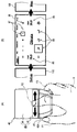
- FIG. 2 is a plan view illustrating the configuration of the operation device in the vehicle.
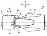
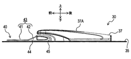
- FIG. 3 is a left side view illustrating the configuration of the operation device.
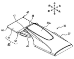
- FIG. 4 is a perspective view illustrating the configuration of the operation device.
- FIG. 5 is a plan view and a left side view illustrating the configuration of the operation unit of the operation device.
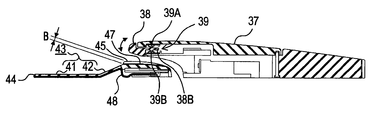
- 6 is a cross-sectional view taken along line VI-VI in FIG.
- FIG. 7 is an enlarged cross-sectional view illustrating a configuration related to the operation unit in FIG. FIG.
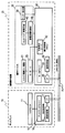
- FIG. 8 is a block diagram showing a part of the control system in the vehicle.
- FIG. 9 is a flowchart showing processing executed in the control system.
- 10A and 10B are explanatory diagrams illustrating an operation example of processing executed in the control system.
- FIGS. 11A and 11B are explanatory diagrams illustrating another operation example of processing executed in the control system.
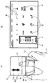
- 12A and 12B are explanatory diagrams illustrating still another operation example of the process executed in the control system.
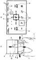
- FIGS. 13A and 13B are explanatory diagrams showing still another operation example of processing executed in the control system.
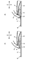
- FIGS. 14A and 14B are explanatory diagrams illustrating the effect of the operation device in comparison with the comparative example.
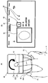
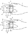
- 15A and 15B are explanatory diagrams illustrating other effects of the operation device.
- the vehicle 1 includes a display 10 and a remote control device 20 provided inside a passenger compartment 3.
- the display 10 is provided on the upper surface or front surface of the dashboard 9 (the front surface when viewed from the driver D), and displays various information on the driver D.
- the remote operation device 20 includes an operation device 30 (an example of an operation device) and an operation control unit 60.
- the operation device 30 is attached to a to-be-attached surface 35 provided on the upper surface of the console 34, and is configured as follows.
- the operation device 30 includes a palm rest 37 on which a palm H (see FIG. 10) of an operator (driver D or a passenger in a passenger seat not shown) is placed, an operation unit 40, It has.
- the operation unit 40 is provided so as to be movable on the attachment surface 35 in any direction, front, back, left, and right.
- the palm rest 37 protrudes upward from the rear side (front side as viewed from the operator) of the operation surface 40 on the attachment surface 35, and then extends forward to reach the upper rear portion of the operation unit 40.
- an enter switch 38 that can be operated in both the upper and lower directions is provided at the front end of the palm rest 37.
- the operation unit 40 includes a touch pad unit 44 whose surface is an operation surface 43 including a first portion 41 and a second portion 42, and is picked up by an operator when the operation unit 40 is moved as described above. And an operation knob 45 to be operated.
- the first portion 41 is formed in a rectangle having sides in the front-rear and left-right directions, and forms a plane parallel to the attachment surface 35.
- the second portion 42 is connected to the rear end of the first portion 41 and is configured to have a rectangular shape whose length in the front-rear direction is smaller than that of the first portion 41.
- the 2nd part 42 comprises the plane which inclined so that it might approach the mounting surface 37A of the palm H in the said palm rest 37, so that the palm rest 37 was approached.
- the operation knob portion 45 is connected to the rear end of the second portion 42 in the touch pad portion 44, and has a thickness (length in the vertical direction) that allows the pair of left and right side surfaces 45A to be easily picked by a finger. is doing.
- a concave portion 47 is formed on the upper surface of the operation knob portion 45 at a portion facing the enter switch 38.
- the pair of left and right side surfaces 45A of the operation knob portion 45 are curved so that the distance in the left-right direction (that is, the width in the left-right direction of the operation knob portion 45) gradually decreases toward the rear. is doing.
- the concave portion 47 is formed on the upper surface of the operation knob portion 45 so as to penetrate in the front-rear direction.
- the recess 47 has a width (a length in the left-right direction) that is at least a front end portion (a portion facing the enter switch 38 when the operation unit 40 is at the reference position) larger than the enter switch 38. A). For this reason, even if the operation part 40 is moved on the to-be-attached surface 35, the recessed part 47 always exists under the enter switch 38.
- the enter switch 38 extends inside the palm rest 37, and the tip 38B is supported inside the palm rest 37 via a hinge (not shown). For this reason, the enter switch 38 can be rotated in the vertical direction as indicated by an arrow in FIG.
- an enter detection unit 39 including two tactile switches 39A and 39B is provided inside the palm rest 37.
- the tactile switch 39A is pressed by a portion of the enter switch 38 accommodated inside the palm rest 37 when a portion exposed to the outside of the palm rest 37 in the enter switch 38 is pulled upward.
- the tactile switch 39 ⁇ / b> B is pressed by a portion housed inside the palm rest 37 in the enter switch 38 when a portion exposed to the outside of the palm rest 37 in the enter switch 38 is pushed downward.
- the depth B of the recess 47 is such a depth that the nail N (see FIG. 14) of the second finger F2 does not touch the recess 47 when such an operation of the enter switch 38 is performed, and the operation can be performed satisfactorily. Designed to.
- an electrostatic electrode path 48 is provided on the lower surface of the touch pad portion 44 over the entire lower surface of both the first portion 41 and the second portion 42.
- the electrostatic electrode path 48 is connected to the electrostatic capacity control unit 49 and detects the electrostatic capacity of each part, thereby detecting which part is touched by the fingertip of the operator.
- the capacitance control unit 49 detects an area having a certain width at the boundary between the first portion 41 and the second portion 42 as a dead zone that does not detect that the fingertip is touched.
- FIG. 8 shows a part extracted from the control system of the vehicle 1 related to the remote control device 20 and the display 10.
- the electrical connection relationships of the respective parts are indicated by solid arrows, but some mechanical connection relationships are also indicated by dashed arrows.
- the slide mechanism 51 that supports the operation unit 40 so as to be slidable along the attachment surface 35 includes a left-right direction (hereinafter also referred to as X-axis direction) and a front-rear direction (hereinafter referred to as Y-axis direction).
- a pair of motors 53 for applying a reaction force to each of them are provided. For this reason, the reaction force can be applied to the operation unit 40 in any direction of 360 ° along the XY plane.
- various well-known mechanisms can be applied. For example, a mechanism disclosed in JP-A-2005-250983 can be applied.
- the detection result of the enter detection unit 39 and the detection result of the capacitance control unit 49 are input to the operation control unit 60 together with the drive amount of the pair of motors 53, and the operation control unit 60 sets the pair of motors 53. Is driven.
- the operation control unit 60 includes a motor driver 61 that drives the pair of motors 53, and a position detection unit 62 that detects the position coordinates of the operation unit 40 in the XY directions based on the drive amount.
- the operation control unit 60 is configured as a microcomputer (ECU) including a CPU, ROM, and RAM, and further includes a communication control unit 66 that communicates with the CAN bus 70 via an interface (I / F) 65. ing.
- the display 10 includes an LCD monitor 11 that displays an image and a display control unit 15 that controls a display state on the LCD monitor 11.
- the display control unit 15 is also configured as a microcomputer including a CPU, a ROM, and a RAM, and performs communication between the display driver 16 that drives the LCD monitor 11 and the CAN bus 70 via an interface (I / F) 17. And a control unit 18.
- FIG. 10B shows an example of a screen displayed on the LCD monitor 11.
- This screen is an air conditioning setting screen 80 for performing settings related to air conditioning in the passenger compartment 3.
- the cursor 81 is moved up and down in the same manner as the operation unit 40 by other processes not shown. It is moved left and right.
- FIG. 10A shows an example in which the operator places the palm H of the right hand on the palm rest 37 and operates the operation unit 40 by gripping the operation unit 40 with the first finger F1 and the third finger F3.
- FIGS. 11A to 15 below also illustrate the case where the operator operates the operation device 30 with the right hand. When the operator operates the operation device 30 with the left hand, substantially the same description can be made, and even in the drawing, the arrangement of the first finger F1 and the third finger F3 is simply changed and there is no significant change.
- the air conditioning setting screen 80 is for setting a pair of temperature setting icons 85 for individually setting the setting temperatures of the driver seat and the passenger seat, a plurality of wind direction setting icons 86 for setting the wind direction, and setting the wind force.
- a plurality of wind power setting icons 87 are provided.
- a reaction force is applied to the operation unit 40 so that the cursor 81 is drawn to the center of the icons 85 to 87.
- a known process such as is executed.
- S9 it is detected at which position on the operation surface 43 the finger is placed, and in S11, it is determined whether or not the finger is placed on the first portion 41. If the finger is placed on the first portion 41 (S11: Y), the process proceeds to S12, and after a two-dimensional input or swipe input is accepted, the process proceeds to S1. On the other hand, if it is determined in S11 that the finger is not placed on the first part 41, that is, placed on the second part (S11N), the process proceeds to S13, and a flick input is accepted. Then, the process proceeds to S1.
- the two-dimensional input in S12 is an input operation in which the operator uses the first portion 41 of the operation surface 43 as a two-dimensional input means such as a handwriting input means.
- the swipe input is an input operation in which the operator strokes the first portion 41 of the operation surface 43 so as to sweep it.
- the flick input in S13 is an input operation in which the operator strokes the second portion 42 of the operation surface 43 so as to play.
- FIG. 11 is a diagram for explaining swipe input.
- FIG. 11B when the cursor 81 is placed on the temperature setting icon 85 on the above-described air conditioning setting screen 80, numerical values (set temperatures) are arranged in the cursor 81 in the vertical direction. Is displayed.
- the first portion 41 is swiped up and down by the second finger F2 (may be another finger; the same applies hereinafter) as shown by an arrow in FIG. 11A (S11: Y )
- the numerical value displayed in the cursor 81 is scrolled up and down (S12).
- the operator can adjust the set temperature of the air conditioning displayed on the temperature setting icon 85 to a desired numerical value.
- FIG. 12 is a diagram for explaining two-dimensional input.
- FIG. 12B shows another example of a screen displayed on the LCD monitor 11.
- This screen is a destination input screen 90 for performing destination input in a car navigation device (not shown).
- the destination input screen 90 includes a cursor 91 that moves in the same manner when the operation unit 40 is moved in the front-rear and left-right directions, a character candidate icon 92 that displays character candidates, and handwriting input that inputs characters by handwriting An area 93 is provided.
- the second finger F2 when a character is handwritten to the first portion 41 by the second finger F2 (S11: Y), the second finger F2 is input to the handwriting input area 93.
- a line is drawn according to the locus of the part touched in (S12). By this operation, the operator can draw a desired character in the handwriting input area 93.
- FIG. 13 is a diagram for explaining flick input.
- the above-described air conditioning setting screen 80 is displayed on the LCD monitor 11, a map screen 100 displaying a map on the left and right, and a setup screen 110 for the operator to set up.
- the software is set so that and are adjacent to each other.
- the second finger F2 is stroked so that the second portion 42 is flipped in the left-right direction (S11: N)
- the entire screen is moved in the stroked direction. It is moved (S13).
- the screen displayed on the LCD monitor 11 can be switched from the air conditioning setting screen 80 to the map screen 100 or the setup screen 110.
- the operation surface 43 that receives an operation input by a fingertip is provided on the surface of the operation unit 40 that receives an operation input by moving in the XY direction. That is, the operation unit 40 has two types of operation devices (an operation knob unit 45 as a main operation device and a touch pad unit 44 as a sub operation device) integrated so that the finger can be changed without changing the operation screen.
- the operation time can be shortened by properly using each operation, and the number of parts of the entire operation device in the vehicle 1 can be reduced to simplify the device configuration.
- the palm rest 37 protrudes from the rear (front side as viewed from the operator) to the upper part of the operation unit 40 with respect to the movement range of the operation unit 40 on the mounted surface 35. That is, all the tangential planes of the placement surface 37 ⁇ / b> A on which the palm H is placed on the palm rest 37 are arranged on the surface side of the operation surface 43. For this reason, the operator (driver D or a passenger in the passenger seat) can satisfactorily operate the operation unit 40 with the palm H placed on the palm rest 37 while sitting.
- the second portion 42 forms a plane that is inclined so as to be closer to the placement surface 37 ⁇ / b> A of the palm H in the palm rest 37 as it approaches the palm rest 37. For this reason, as shown to FIG. 14 (A), the angle
- the first portion 41 and the second portion 42 are a series of planes parallel to the mounted surface 35, and the rear end of the second portion 42 If the operation knob portion 45 is provided so as to stand up, the operability may be lowered. In this case, when the second portion 42 is operated, the nail N of the second finger F2 that operates the portion hits the second portion 42, and the operability of the second portion 42 may be reduced. .
- the angle formed between the tangent plane on the belly of the second finger F2 that operates the second portion 42 and the second portion 42 is small, and thus the second portion It is suppressed that the nail
- the inclination angle of the second portion 42 with respect to the attachment surface 35 has an optimum value depending on the apparatus configuration, but is preferably about 45 ° (30 ° to 60 °), for example.
- the pair of left and right side surfaces 45A of the operation knob 45 is curved so that the distance in the left-right direction (the width in the direction to be picked) gradually decreases toward the rear. Therefore, an operator having a small palm H and a small interval W1 between the fingertip of the first finger F1 and the fingertip of the third finger F3 when the operation knob portion 45 is picked is shown in FIG. What is necessary is just to pick the back of the part 45.
- FIG. an operator who has a large palm H and has a large interval W2 between the fingertip of the first finger F1 and the fingertip of the third finger F3 when gripping the operation knob portion 45 is shown in FIG. What is necessary is just to pick the front of the part 45.
- FIG. Therefore, the operation unit 40 in the present embodiment can be operated satisfactorily regardless of the size of the hand.
- the mounted surface 35 is the support surface
- the palm rest 37 is the palm rest
- the first portion 41 is the first portion
- the second portion 42 is the second portion
- the operation surface 43 corresponds to the operation surface
- the operation unit 40 corresponds to the operation unit
- the pair of motors 53 corresponds to the movement prohibition unit
- the pair of left and right side surfaces 45A of the operation knob unit 45 corresponds to the knob
- the enter switch 38 corresponds to the switch.
- the embodiment is not limited to the above-described embodiment, and includes various embodiments.
- the knob portion of the operation knob portion 45 may be configured in a simple rectangle, or the side surface of the touch pad portion 44 may be directly picked without the knob portion.
- the touch pad unit 44 is fixed to the attachment surface 35 and may not have a function as an operation unit that can move in the XY directions.
- the operation surface 43 may not be divided into the first part 41 and the second part 42, and the whole may be configured as a series of curved surfaces. Also in that case, if the portion near the palm rest 37 of the operation surface 43 is inclined so as to be closer to the placement surface 37 ⁇ / b> A as the palm rest 37 is closer than the portion away from the palm rest 37, FIG. 14 is used. The above-described effects described above occur. In this case, the operation surface 43 may be divided into the 1st part 41 and the 2nd part 42 from which the operation object received is different, and does not need to be divided.
- the operation targets received for the respective portions are different. Can be used properly. For this reason, the operator can determine whether the second finger F2 is in contact with the first portion 41 or the second portion 42 without looking at the operation surface 43, and so-called blind operation is possible. It becomes.
- the 1st part 41 and the 2nd part 42 may be comprised by the independent separate touchscreen.
- an area having a certain width at the boundary between the first part 41 and the second part 42 is a dead band that does not detect whether the fingertip is touched.
- a dead band is provided. It does not have to be.
- the operation with respect to the first portion 41 and the operation with respect to the second portion 42 can be more clearly distinguished when such a dead zone is provided.
- the enter switch 38 does not necessarily need to be provided, and even if the enter switch 38 is provided, the corresponding recess 47 may not necessarily be provided.
- the operation device 30 of the above-described embodiment includes the enter switch 38 that is operated in the direction of approaching or separating from the operation unit 40 at the end of the palm rest 37 on the operation surface 43 side. A recess 47 is formed in the operation unit 40 at a position facing the enter switch 38. For this reason, the situation that the nail
- the operability of the enter switch 38 may be ensured without providing the recess 47.
- the distance from the mounting surface 37A is increased, and the operability of the operation knob 45 may be lowered.
- the concave portion 47 is provided as in the above-described embodiment, the interval between the operation knob portion 45 and the mounting surface 37A is reduced to ensure the operability of the operation knob portion 45, while Thus, the operability of the enter switch 38 can be ensured.
- the use of the operating device is not limited to the above-described embodiment.
- the operating device may be provided on a dashboard, a steering wheel, or a door trim.
- the operating device can be used for various purposes other than the vehicle, and may be provided in, for example, a personal computer or a peripheral device thereof.
- the configurations of the above-described embodiment and each modification can be arbitrarily combined.
Landscapes
- Engineering & Computer Science (AREA)
- General Engineering & Computer Science (AREA)
- Theoretical Computer Science (AREA)
- Human Computer Interaction (AREA)
- Physics & Mathematics (AREA)
- General Physics & Mathematics (AREA)
- Mechanical Engineering (AREA)
- Chemical & Material Sciences (AREA)
- Combustion & Propulsion (AREA)
- Transportation (AREA)
- User Interface Of Digital Computer (AREA)
- Position Input By Displaying (AREA)
Abstract
操作部(40)と、パームレスト(37)と、を備える操作装置を提供する。 操作部(40)は、指先による操作入力を受け付ける操作面(43)を備える。パームレスト(37)は、操作者から見て操作面(43)よりも手前側に設けられ、操作者の掌が載置されるパームレスト(37)であって、掌の載置面(37A)の接平面が操作面(43)の表面側に配置されている。操作面(43)は、パームレスト(37)に近い部分が、パームレスト(37)から離れた部分に比べて、パームレスト(37)に近づくほどパームレスト(37)における掌の載置面(37A)に近接するように傾斜している操作装置。
Description
本出願は、2014年4月10日に出願された日本国特許出願2014-81297号に基づくものであり、この開示をここに参照により援用する。
本開示は、操作者の指先による操作入力を受け付ける操作面と操作者の掌が載置されるパームレストとを備えた操作装置、及び、その操作装置を備えた車両に関する。
従来、この種の操作装置として、個々に操作面を有する2つのタッチパッドを非平行に組み合わせて、2つのタッチパッドが接する部分に凸部を形成し、パームレストを前記凸部よりも低い位置に設けたものが提案されている(例えば、特許文献1参照。)。
操作装置に関し本願発明者は、以下を見出した。
操作装置が、車両のコンソールや運転席の肘掛け等の上面に設けられ、ドライバまたは助手席の同乗者によって操作される場合、パームレストにおける掌の載置面はタッチパッドの操作面よりも上方に設けた方が操作性が向上する。すなわち、前記掌の載置面の接平面がタッチパッドの操作面の表面側に配置された方が、操作性が向上する。前記掌の載置面がタッチパッドの操作面よりも上方にある場合に、特許文献1に記載のタッチパッドの構成が採用されると、パームレストに近い操作面が、パームレストに近づくほど前記載置面から離れるように傾斜し、爪が操作面に当たりやすくなる。
そこで、本開示は、操作者の指先による操作入力を受け付ける操作面と操作者の掌が載置されるパームレストとを備えた操作装置、及び、その操作装置を備えた車両において、操作面の操作性を広い領域に亘って確保することを目的としてなされた。
本開示の一例に係る操作装置では、操作者の掌が載置されるパームレストと、指先による操作入力を受け付ける操作面を備えた操作部とを備えている。パームレストは、操作面よりも操作者から見て手前側に設けられ、かつ、前記掌の載置面の接平面が前記操作面の表面側に(例えば、操作面が上方を向いている場合は操作面よりも上方に)配置される。このため、操作面の操作性がよい。また、操作面は、パームレストに近い部分が、パームレストから離れた部分に比べて、パームレストに近づくほど当該パームレストにおける掌の載置面に近接するように傾斜している。このため、操作面のパームレストに近い部分が操作される場合でも、操作面のパームレストから遠い部分が操作される場合でも、その操作面を操作する指の腹における接平面と、操作面とのなす角が小さくなる。従って、操作面の操作性を広い領域に亘って確保することができる。
なお、前記操作部は、当該操作部が移動されることによる操作入力も受け付けてもよい。その場合、操作部は、操作面が指先による操作入力を受け付け、自身が移動されることによっても操作入力を受け付ける。このため、1つの操作部で2種類の操作入力を受け付けることができ、操作画面に応じて指の持ち替えなしに各操作を使い分けることによる操作時間の短縮と、操作装置全体として必要になる部品点数を減らすることができる。また、その場合さらに、前記操作面が前記操作入力を受け付けているとき、モータの駆動制御により前記操作部の移動を禁止してもよい。その場合、操作面の操作時には当該操作面が移動しないので、操作面の操作性を一層良好に確保することができる。
本開示についての上記および他の目的、特徴や利点は、添付の図面を参照した下記の詳細な説明から、より明確になる。添付図面において
図1は、実施形態の車両の構成を表す模式図である。
図2は、車両における操作デバイスの構成を表す平面図である。
図3は、操作デバイスの構成を表す左側面図である。
図4は、操作デバイスの構成を表す斜視図である。
図5は、操作デバイスの操作部の構成を表す平面図及び左側面図である。
図6は、図2のVI-VI線断面図である。
図7は、図6における操作部に係る構成を拡大して示す断面図である。
図8は、車両における制御系の一部を表すブロック図である。
図9は、制御系で実行される処理を表すフローチャートである。
図10(A)及び(B)は、制御系で実行される処理の動作例を表す説明図である。
図11(A)及び(B)は、制御系で実行される処理の他の動作例を表す説明図である。
図12(A)及び(B)は、制御系で実行される処理の更に他の動作例を表す説明図である。
図13(A)及び(B)は、制御系で実行される処理の更に他の動作例を表す説明図である。
図14(A)及び(B)は、操作デバイスの効果を比較例と対比して表す説明図である。
図15(A)及び(B)は、操作デバイスの他の効果を表す説明図である。
[実施形態の構成]
次に、実施形態を図面と共に説明する。図1に示すように、本実施形態の車両1は、車室3の内部に設けられたディスプレイ10と遠隔操作装置20とを備えている。ディスプレイ10は、ダッシュボード9の上面又は正面(ドライバDから見て手前側の面)に設けられて、ドライバDに各種情報を表示する。遠隔操作装置20は、操作デバイス30(操作装置の一例)と操作制御部60とを備えている。操作デバイス30は、コンソール34の上面に設けられた被取付面35に取り付けられ、次のように構成されている。
次に、実施形態を図面と共に説明する。図1に示すように、本実施形態の車両1は、車室3の内部に設けられたディスプレイ10と遠隔操作装置20とを備えている。ディスプレイ10は、ダッシュボード9の上面又は正面(ドライバDから見て手前側の面)に設けられて、ドライバDに各種情報を表示する。遠隔操作装置20は、操作デバイス30(操作装置の一例)と操作制御部60とを備えている。操作デバイス30は、コンソール34の上面に設けられた被取付面35に取り付けられ、次のように構成されている。
図2~図4に示すように、操作デバイス30は、操作者(ドライバDまたは図示しない助手席の同乗者)の掌H(図10参照)が載置されるパームレスト37と、操作部40とを備えている。操作部40は、被取付面35上を前後左右任意の方向に移動可能に設けられている。パームレスト37は、被取付面35における操作部40の移動範囲よりも後方(操作者から見て手前側)から上方に突出し、続いて前方に延出して操作部40の移動範囲の後部上方まで達している。また、パームレスト37の前端には、上下両方向に操作可能なエンタースイッチ38が設けられている。
操作部40は、表面が第1の部分41と第2の部分42とからなる操作面43とされたタッチパッド部44と、当該操作部40を前述のように移動させる際に操作者によって摘まれる操作ノブ部45とから構成されている。第1の部分41は、前後左右方向に辺を備えた矩形に構成され、被取付面35と平行な平面を構成している。第2の部分42は、第1の部分41の後端に連接され、前後方向の長さが第1の部分41に比べて小さい矩形に構成されている。また、第2の部分42は、パームレスト37に近づくほど当該パームレスト37における掌Hの載置面37Aに近接するように傾斜した平面を構成している。
操作ノブ部45は、タッチパッド部44における第2の部分42の後端に連接され、左右一対の側面45Aを指で容易に摘むことができる程度の肉厚(上下方向の長さ)を有している。また、操作ノブ部45の上面には、エンタースイッチ38との対向部に、凹部47が形成されている。
ここで、図5に示すように、操作ノブ部45の左右一対の側面45Aは、左右方向の間隔(すなわち操作ノブ部45の左右方向の幅)が後方へ行くほど徐々に狭くなるように湾曲している。また、凹部47は、操作ノブ部45の上面に前後方向に貫通するように形成されている。
さらに、図2に示すように、凹部47は、少なくとも前端部(操作部40が基準の位置にあるときにエンタースイッチ38と対向する部分)が、エンタースイッチ38よりも大きい幅(左右方向の長さ)を有している。このため、操作部40が被取付面35上を移動されても、エンタースイッチ38の下方には凹部47が常に存在する。
図6に示すように、エンタースイッチ38は、パームレスト37の内部に延びており、その先端38Bは、図示省略したヒンジ(図示省略)を介してパームレスト37の内部に支持されている。このため、エンタースイッチ38は、図6に矢印で示すように上下方向に回動可能となっている。また、パームレスト37の内部には、2つのタクタイルスイッチ39A,39Bを備えたエンター検出部39が設けられている。タクタイルスイッチ39Aは、エンタースイッチ38におけるパームレスト37外部に露出した部分が上方に引かれたときに、そのエンタースイッチ38におけるパームレスト37内部に収容された部分によって押下される。タクタイルスイッチ39Bは、エンタースイッチ38におけるパームレスト37外部に露出した部分が下方に押されたときに、そのエンタースイッチ38におけるパームレスト37内部に収容された部分によって押下される。凹部47の深さBは、このようなエンタースイッチ38の操作が行われるときに第2指F2の爪N(図14参照)が凹部47に触れず、当該操作が良好に行える程度の深さに設計されている。
また、図7に示すように、タッチパッド部44の下面には、第1の部分41及び第2の部分42の双方の下面全域に亘って、静電電極経路48が設けられている。静電電極経路48は、図8に示すように静電容量制御部49に接続されて各部の静電容量を検出されることにより、どの部分が操作者の指先に触れられているかを検出する。なお、静電容量制御部49は、第1の部分41と第2の部分42との境界における一定幅を有する領域を、指先に触れられていることを検出しない不感帯として検出を行う。
図8は、車両1の制御系のうち、遠隔操作装置20とディスプレイ10とに関連する部分を抜粋して示している。また、図8には、各部の電気的な接続関係が実線の矢印で示されているが、一部の機械的な接続関係も破線の矢印で示されている。図8に示すように、操作部40を被取付面35に沿ってスライド可能に支持するスライド機構51には、左右方向(以下、X軸方向ともいう。)及び前後方向(以下、Y軸方向ともいう。)それぞれに反力を加える一対のモータ53が設けられている。このため、操作部40には、XY平面に沿った360°どの方向へも反力が付与可能である。なお、このように操作部40に反力を付与する機構としては、周知の種々の機構が適用可能であるが、例えば、特開2005-250983号公報に開示された機構が適用可能である。
また、前述のエンター検出部39の検出結果と、静電容量制御部49の検出結果とは、一対のモータ53の駆動量と共に操作制御部60に入力され、操作制御部60によって一対のモータ53が駆動される。
操作制御部60は、一対のモータ53を駆動するモータドライバ61と、その駆動量に基づいて操作部40のXY方向の位置座標を検出する位置検出部62とを備えている。この操作制御部60は、CPU,ROM,RAMを備えたマイクロコンピュータ(ECU)として構成され、さらに、インタフェース(I/F)65を介してCANバス70との通信を行う通信制御部66も備えている。
ディスプレイ10は、画像を表示するLCDモニタ11と、そのLCDモニタ11における表示状態を制御する表示制御部15とを備えている。表示制御部15も、CPU,ROM,RAMを備えたマイクロコンピュータとして構成され、LCDモニタ11を駆動するディスプレイドライバ16と、インタフェース(I/F)17を介してCANバス70との通信を行う通信制御部18とを備えている。
[実施形態における制御]
操作制御部60のCPUは、電源が投入されると、操作制御部60のROMに記憶されたプログラムに基づいて図9に示す処理を実行する。図9に示すように、この処理では、先ずS1(Sはステップを表す:以下同様)にて、静電容量制御部49からの信号に基づき、操作面43に指が置かれているか否かが判断される。指が置かれていない場合は(S1:N)、処理はS2へ移行し、エンター検出部39の検出結果に基づき、エンタースイッチ38が操作(ENTER操作)されているか否かが判断される。エンタースイッチ38が操作されていない場合は(S2:N)、処理はS3へ移行し、操作部40に通常の反力を付与する通常反力制御が実行された後、処理は前述のS1へ移行する。この通常反力制御とは、例えば次のような処理である。
操作制御部60のCPUは、電源が投入されると、操作制御部60のROMに記憶されたプログラムに基づいて図9に示す処理を実行する。図9に示すように、この処理では、先ずS1(Sはステップを表す:以下同様)にて、静電容量制御部49からの信号に基づき、操作面43に指が置かれているか否かが判断される。指が置かれていない場合は(S1:N)、処理はS2へ移行し、エンター検出部39の検出結果に基づき、エンタースイッチ38が操作(ENTER操作)されているか否かが判断される。エンタースイッチ38が操作されていない場合は(S2:N)、処理はS3へ移行し、操作部40に通常の反力を付与する通常反力制御が実行された後、処理は前述のS1へ移行する。この通常反力制御とは、例えば次のような処理である。
図10(B)は、LCDモニタ11に表示される画面の一例を表している。この画面は、車室3内の空調に関する設定を行うための空調設定画面80である。この空調設定画面80では、図10(A)に矢印で示すように操作部40が前後左右方向に移動されると、図示省略した他の処理によって、カーソル81が、操作部40と同様に上下左右方向に移動される。なお、図10(A)には、操作者が右手の掌Hをパームレスト37に載置して、第1指F1と第3指F3によって操作部40を摘んで操作する例を図示している。以下の図11(A)~図15でも、操作者が操作デバイス30を右手で操作する場合を例にとって図示している。操作者が左手で操作デバイス30を操作する場合もほぼ同様の説明が可能で、図面としても第1指F1と第3指F3との配置が入れ替わるだけで大きな変化はない。
空調設定画面80は、運転席及び助手席の設定温度を個々に設定するための一対の温度設定用アイコン85、風向を設定するための複数の風向設定用アイコン86、及び、風力を設定するための複数の風力設定用アイコン87を備えている。S3の通常反力制御では、カーソル81がいずれかのアイコン85~87の近傍に配置されたとき、カーソル81がそのアイコン85~87の中心に引き込まれるような反力を操作部40に付与するなどといった周知の処理が実行される。
図9に戻って、S2にてエンタースイッチ38が操作されたと判断された場合は(S2:N)、処理はS5へ移行し、その操作が押し下げであるか否かが判断される。操作が押し下げである場合は(S5:Y)、S6にて設定処理がなされた後、処理はS1へ移行する。一方、S5にて、操作が押し下げでない、すなわち操作が引き上げであると判断された場合は(S5:N)、S7にて取消処理が実行された後、処理はS1へ移行する。
このため、例えば図10(B)の空調設定画面80における所望の風向設定用アイコン86または所望の風力設定用アイコン87の上にカーソル81が配置された状態でエンタースイッチ38が押し下げられると(S2:Y、S5:Y)、そのカーソル81の配置に応じた風向または風力が設定される(S6)。一方、操作者がエンタースイッチ38を誤って押し下げた場合は、即座にそのエンタースイッチ38を引き上げることで(S2:Y、S5:N)、一旦設定された入力を取り消すことができる(S7)。
また、S1にて操作面43に指(例えば、図10(A)に示す第2指F2)が置かれていると判断された場合は(S1:Y)、処理はS8へ移行する。S8では、一対のモータ53から操作部40に加えられる反力が最大値にセットされ、操作部40が移動しないようにロックされる。この処理により、操作面43(パッド面)が移動しなくなるので、操作面43の操作性が向上する。
なお、このように一対のモータ53から操作部40に加えられる反力を最大値にセットして操作部40の移動を禁止する構成は、例えば特開2009-255609号公報に詳しいので、ここでは詳述しない。また、S8へ処理が移行した時点ですでに操作部40がロックされていた場合は、このS8の処理は実質的に素通りされる。
S8に続くS9では、操作面43上のどの位置に指が置かれているかが検出され、S11にて、指が第1の部分41に置かれているか否かが判断される。指が第1の部分41に置かれている場合は(S11:Y)、処理はS12へ移行し、二次元入力またはスワイプ入力が受け付けられた後、処理はS1へ移行する。一方、S11にて、指が第1の部分41に置かれていない、すなわち第2の部分に置かれていると判断された場合は(S11N)、処理はS13へ移行し、フリック入力が受け付けられた後、処理はS1へ移行する。
ここで、S12における二次元入力とは、操作者が、操作面43の第1の部分41を手書き入力手段等のように二次元的な入力手段として使用する入力操作である。また、スワイプ入力とは、操作者が、操作面43の第1の部分41を掃くように撫でる入力操作である。さらに、S13におけるフリック入力とは、操作者が、操作面43の第2の部分42を弾くように撫でる入力操作である。以下、これらの入力操作について、具体的な例を挙げて説明する。
図11は、スワイプ入力について説明する図である。例えば、図11(B)に示すように、前述の空調設定画面80において、カーソル81が温度設定用アイコン85の上に配置されると、カーソル81内に上下方向に並べて数値(設定温度)が表示される。このとき、第1の部分41が、図11(A)に矢印で示すように第2指F2(他の指であってもよい:以下同様)によって上下方向にスワイプされると(S11:Y)、カーソル81内に表示された数値が上下にスクロールされる(S12)。この操作によって、操作者は、温度設定用アイコン85に表示される空調の設定温度を、所望の数値に調整することができる。
図12は、二次元入力について説明する図である。図12(B)は、LCDモニタ11に表示される画面の他の例を表している。この画面は、カーナビゲーション装置(図示省略)における目的地入力を行うための目的地入力画面90である。この目的地入力画面90は、操作部40が前後左右方向に移動されたときに同様に移動するカーソル91の他、文字の候補を表示する文字候補アイコン92、及び、文字を手書き入力する手書き入力エリア93を備えている。このとき、図12(A)に矢印で示すように、第2指F2によって第1の部分41に文字が手書きで入力されると(S11:Y)、手書き入力エリア93に、第2指F2で触れられた部分の軌跡に応じた線が描かれる(S12)。この操作によって、操作者は、手書き入力エリア93に、所望の文字を描くことができる。
図13は、フリック入力について説明する図である。例えば、図13(B)に示すように、LCDモニタ11に前述の空調設定画面80が表示され、その左右に、地図を表示する地図画面100と、操作者がセットアップを行うためのセットアップ画面110とが隣接配置されるように、ソフトウェア上の設定がなされているとする。このとき、図13(A)に矢印で示すように、第2指F2によって第2の部分42が左右方向に弾くように撫でられると(S11:N)、その撫でられた方向に画面全体が移動される(S13)。その結果、LCDモニタ11に表示される画面を、空調設定画面80から、地図画面100またはセットアップ画面110に切り換えることができる。
[実施形態の効果]
以上説明したように、操作デバイス30では、XY方向に移動されることによって操作入力を受け付ける操作部40の表面に、指先による操作入力を受け付ける操作面43が設けられている。すなわち、操作部40は、2種類の操作機器(主操作機器としての操作ノブ部45と副操作機器としてのタッチパッド部44)が一体化されており、操作画面に応じて指の持ち替えなしに各操作を使い分けることによる操作時間短縮と、車両1内における操作機器全体としての部品点数を減らして装置構成を簡略化することができる。
以上説明したように、操作デバイス30では、XY方向に移動されることによって操作入力を受け付ける操作部40の表面に、指先による操作入力を受け付ける操作面43が設けられている。すなわち、操作部40は、2種類の操作機器(主操作機器としての操作ノブ部45と副操作機器としてのタッチパッド部44)が一体化されており、操作画面に応じて指の持ち替えなしに各操作を使い分けることによる操作時間短縮と、車両1内における操作機器全体としての部品点数を減らして装置構成を簡略化することができる。
また、前述のように、パームレスト37は、被取付面35における操作部40の移動範囲よりも後方(操作者から見て手前側)から操作部40の上方まで突出している。すなわち、パームレスト37における掌Hが載置される載置面37Aの全ての接平面が、操作面43の表面側に配置される。このため、操作者(ドライバDまたは助手席の同乗者)は、着座したままパームレスト37に掌Hを載せた状態で、良好に操作部40を操作することができる。
また、第2の部分42は、パームレスト37に近づくほど当該パームレスト37における掌Hの載置面37Aに近接するように傾斜した平面を構成している。このため、図14(A)に示すように、第2の部分42を操作する指(第2指F2)の腹における接平面と第2の部分42とのなす角が小さくなる。従って、本実施形態の操作デバイス30では、第2の部分42の操作性を向上させることができる。
すなわち、図14(B)に比較例として示すように、第1の部分41と第2の部分42とが、被取付面35に平行な一連の平面とされ、第2の部分42の後端から操作ノブ部45が切り立って設けられていると、操作性が低下する場合がある。この場合、第2の部分42が操作される際に、当該部分を操作する第2指F2の爪Nが第2の部分42に当たって、当該第2の部分42の操作性が低下する場合がある。これに対して、本実施形態の操作デバイス30では、第2の部分42を操作する第2指F2の腹における接平面と第2の部分42とのなす角が小さくなるので、第2の部分42に爪Nが当たるのが抑制され、当該第2の部分42の操作性を向上させることができる。なお、第2の部分42の被取付面35に対する傾斜角は、装置構成によって最適な値が異なるが、例えば45°程度(30°~60°)とされるのが好ましい。
また、操作ノブ部45の左右一対の側面45Aは、左右方向の間隔(摘まれる方向の幅)が後方へ行くほど徐々に狭くなるように湾曲している。このため、掌Hが小さく、操作ノブ部45を摘むときの第1指F1の指先と第3指F3の指先との間隔W1が小さい操作者は、図15(A)に示すように操作ノブ部45の後方を摘めばよい。逆に、掌Hが大きく、操作ノブ部45を摘むときの第1指F1の指先と第3指F3の指先との間隔W2が大きい操作者は、図15(B)に示すように操作ノブ部45の前方を摘めばよい。従って、本実施形態における操作部40は、手の大きさに拘わらず良好に操作されることができる。
なお、上述の実施形態において、被取付面35が支持面に、パームレスト37がパームレストに、第1の部分41が第1の部分に、第2の部分42が第2の部分に、操作面43が操作面に、操作部40が操作部に、一対のモータ53が移動禁止部に、操作ノブ部45の左右一対の側面45Aが摘み部に、エンタースイッチ38がスイッチに、それぞれ相当する。
また、実施形態は上述の実施形態に何ら限定されるものではなく、種々の実施形態を含むで。例えば、操作ノブ部45の左右一対の側面45Aは、それぞれ階段状に構成されていても、図15を用いて説明したような効果が生じる。また、そのような効果は生じなくなるが、操作ノブ部45の摘み部は単純な矩形に構成されていてもよく、摘み部がなくタッチパッド部44の側面が直接摘まれてもよい。さらに、タッチパッド部44は被取付面35に固定され、XY方向に移動可能な操作部としての機能を有していなくてもよい。
また、上述の実施形態では、操作面43が操作されるときに(S1:Y)、操作部40が移動しないように一対のモータ53によって操作部40の位置が固定されているが(S8)、必ずしもそのような制御はなされなくてもよい。ただし、上述の実施形態では、操作面43が操作されるときに操作部40の位置が固定されるので、操作面43の操作性を一層向上させることができる。
また、操作面43は、第1の部分41と第2の部分42とに分かれていなくてもよく、全体が一連の曲面として構成されていてもよい。その場合も、操作面43のパームレスト37に近い部分が、パームレスト37から離れた部分に比べて、パームレスト37に近づくほど載置面37Aに近接するように傾斜していれば、図14を用いて説明した前述の効果が生じる。この場合、操作面43は、受け付けられる操作対象の異なる第1の部分41と第2の部分42とに分かれていてもよく、分かれていなくてもよい。
ただし、上述の実施形態における操作面43では、第1の部分41と第2の部分42とが互いに非平行な平面として構成されているので、それぞれの部分に対して受け付けられる操作対象を異ならせて確実に使い分けることが可能となる。また、このため、第1の部分41または第2の部分42のいずれに第2指F2が触れているかを、操作面43を見なくても操作者自身が判断可能となり、いわゆるブラインド操作が可能となる。また、第1の部分41と第2の部分42とは、独立した別体のタッチパネルで構成されてもよい。
また、上述の実施形態では、第1の部分41と第2の部分42との境界における一定幅を有する領域を、指先に触れられているかを検出しない不感帯としているが、このような不感帯は設けなくてもよい。ただし、このような不感帯が設けられた方が、第1の部分41に対する操作と第2の部分42に対する操作とを一層明確に区別することができる。
また、エンタースイッチ38は必ずしも設けられなくてもよく、仮にエンタースイッチ38が設けられたとしても、それに対応する凹部47は必ずしも設けられなくてもよい。ただし、上述の実施形態の操作デバイス30は、パームレスト37の操作面43側端部に、操作部40に近接または離間する方向に操作されるエンタースイッチ38を備えている。そして、操作部40には、エンタースイッチ38との対向位置に凹部47が形成されている。このため、エンタースイッチ38の操作時に爪Nが操作部40に当たるなどの事態が回避され、エンタースイッチ38の操作性を向上させることができる。
エンタースイッチ38と操作ノブ部45との上下方向の間隔が大きい場合には、凹部47を設けなくてもエンタースイッチ38の操作性が確保される場合があるが、その場合、操作ノブ部45と載置面37Aとの間隔が大きくなり、操作ノブ部45の操作性が低下することがある。これに対して、上述の実施形態のように凹部47を設けた場合は、操作ノブ部45と載置面37Aとの間隔を小さくして操作ノブ部45の操作性を確保しつつ、前述のようにエンタースイッチ38の操作性も確保することができる。
また、操作装置の用途も、上述の実施形態に何ら限定されるものではない。例えば、操作装置は、ダッシュボードやステアリングホイール、ドアトリムに設けられてもよい。さらに、操作装置は、車両以外にも種々の用途に使用することができ、例えば、パーソナルコンピュータまたはその周辺機器に設けられてもよい。また、上述の実施形態及び各変形例の構成は任意に組み合わせることができる。
Claims (9)
- 指先による操作入力を受け付ける操作面(43)を備えた操作部(40)と、
操作者から見て前記操作面よりも手前側に設けられ、操作者の掌(H)が載置されるパームレスト(37)であって、前記掌の載置面(37A)の接平面が前記操作面の表面側に配置されるパームレストと、
を備え、
前記操作面は、前記パームレストに近い部分が、前記パームレストから離れた部分に比べて、前記パームレストに近づくほど前記パームレストにおける掌の載置面に近接するように傾斜している操作装置。 - 前記操作面は、前記パームレストから離れた第1の部分(41)と、前記パームレストに近い第2の部分(42)とから構成され、
前記第1の部分は、前記操作面を支持する支持面(35)に平行な平面状に構成され、
前記第2の部分は、前記パームレストに近づくほど前記パームレストにおける掌の載置面(37A)に近接するように傾斜した平面状に構成され、
前記第1の部分と前記第2の部分とでは、当該部分によって受け付けられる操作入力の操作対象が異なる請求項1に記載の操作装置。 - 前記第1の部分と前記第2の部分との境界における一定幅を有する領域は、前記指先による操作入力を受け付けない領域とされた請求項2に記載の操作装置。
- 前記操作部は、当該操作部が移動されることによる操作入力も受け付ける請求項1~3のいずれか1項に記載の操作装置。
- 前記操作面が前記操作入力を受け付けているとき、前記操作部の移動を禁止する移動禁止部(53)を、
更に備える請求項4に記載の操作装置。 - 前記操作部は、前記操作面が設けられた部分よりも前記パームレスト側に、操作者が当該操作部を移動させるために摘むための摘み部(45A)を備える請求項4または5に記載の操作装置。
- 前記摘み部は、摘まれる方向の幅が異なる複数の部分を有する請求項6に記載の操作装置。
- 前記パームレストの前記操作面側端部に設けられ、前記操作部に近接または離間する方向に操作されるスイッチ(38)を、
更に備え、
前記操作部には、前記スイッチとの対向位置に凹部(47)が形成されている請求項4~7のいずれか1項に記載の操作装置。 - 請求項1~8のいずれか1項に記載の操作装置を備える車両。
Priority Applications (1)
| Application Number | Priority Date | Filing Date | Title |
|---|---|---|---|
| US15/300,804 US9965061B2 (en) | 2014-04-10 | 2015-04-06 | Input device and vehicle |
Applications Claiming Priority (2)
| Application Number | Priority Date | Filing Date | Title |
|---|---|---|---|
| JP2014-081297 | 2014-04-10 | ||
| JP2014081297A JP6273989B2 (ja) | 2014-04-10 | 2014-04-10 | 操作装置及び車両 |
Publications (1)
| Publication Number | Publication Date |
|---|---|
| WO2015155973A1 true WO2015155973A1 (ja) | 2015-10-15 |
Family
ID=54287559
Family Applications (1)
| Application Number | Title | Priority Date | Filing Date |
|---|---|---|---|
| PCT/JP2015/001914 Ceased WO2015155973A1 (ja) | 2014-04-10 | 2015-04-06 | 操作装置及び車両 |
Country Status (3)
| Country | Link |
|---|---|
| US (1) | US9965061B2 (ja) |
| JP (1) | JP6273989B2 (ja) |
| WO (1) | WO2015155973A1 (ja) |
Cited By (3)
| Publication number | Priority date | Publication date | Assignee | Title |
|---|---|---|---|---|
| JP2018099976A (ja) * | 2016-12-20 | 2018-06-28 | トヨタ自動車九州株式会社 | 車両用操作部構造 |
| EP3421300A4 (en) * | 2016-02-23 | 2019-12-18 | KYOCERA Corporation | CONTROL UNIT FOR A VEHICLE |
| US20240004416A1 (en) * | 2020-12-02 | 2024-01-04 | Bayerische Motoren Werke Aktiengesellschaft | Operating Element for a Motor Vehicle |
Families Citing this family (7)
| Publication number | Priority date | Publication date | Assignee | Title |
|---|---|---|---|---|
| USD829765S1 (en) * | 2015-09-28 | 2018-10-02 | Everi Games Inc. | Display screen or portion thereof with animated graphical user interface |
| TWI678656B (zh) * | 2018-05-09 | 2019-12-01 | 和碩聯合科技股份有限公司 | 電腦系統及其介面操作方法 |
| USD944869S1 (en) | 2018-09-07 | 2022-03-01 | Crown Equipment Corporation | Arm pad |
| USD944868S1 (en) | 2018-09-07 | 2022-03-01 | Crown Equipment Corporation | Arm pad |
| USD922279S1 (en) | 2018-10-17 | 2021-06-15 | Crown Equipment Corporation | Control pod |
| DE102020000729A1 (de) * | 2020-02-04 | 2021-08-05 | Man Truck & Bus Se | Anordnung einer Handballenauflage und eines Bedienelements für ein Fahrzeug |
| US11796660B2 (en) * | 2020-07-24 | 2023-10-24 | Fujifilm Sonosite, Inc. | Systems and methods for customized user interface |
Citations (1)
| Publication number | Priority date | Publication date | Assignee | Title |
|---|---|---|---|---|
| US6025831A (en) * | 1997-11-19 | 2000-02-15 | Avrotec, Inc. | Method and apparatus for accurate controls input |
Family Cites Families (7)
| Publication number | Priority date | Publication date | Assignee | Title |
|---|---|---|---|---|
| JP4220416B2 (ja) | 2004-03-05 | 2009-02-04 | アルプス電気株式会社 | 力覚付与型入力装置 |
| US8319832B2 (en) * | 2008-01-31 | 2012-11-27 | Denso Corporation | Input apparatus and imaging apparatus |
| JP4891286B2 (ja) | 2008-04-11 | 2012-03-07 | 株式会社デンソー | 遠隔操作装置 |
| JP2013235359A (ja) | 2012-05-08 | 2013-11-21 | Tokai Rika Co Ltd | 情報処理装置及び入力装置 |
| JP2014133474A (ja) | 2013-01-10 | 2014-07-24 | Denso Corp | 車載用入力装置 |
| JP6020319B2 (ja) | 2013-04-10 | 2016-11-02 | 株式会社デンソー | 操作装置 |
| FR3019661B1 (fr) * | 2014-04-04 | 2017-07-14 | Thales Sa | Amelioration de l'ergonomie d'un dispositif d'entree de donnees |
-
2014
- 2014-04-10 JP JP2014081297A patent/JP6273989B2/ja not_active Expired - Fee Related
-
2015
- 2015-04-06 WO PCT/JP2015/001914 patent/WO2015155973A1/ja not_active Ceased
- 2015-04-06 US US15/300,804 patent/US9965061B2/en not_active Expired - Fee Related
Patent Citations (1)
| Publication number | Priority date | Publication date | Assignee | Title |
|---|---|---|---|---|
| US6025831A (en) * | 1997-11-19 | 2000-02-15 | Avrotec, Inc. | Method and apparatus for accurate controls input |
Cited By (5)
| Publication number | Priority date | Publication date | Assignee | Title |
|---|---|---|---|---|
| EP3421300A4 (en) * | 2016-02-23 | 2019-12-18 | KYOCERA Corporation | CONTROL UNIT FOR A VEHICLE |
| US11221735B2 (en) | 2016-02-23 | 2022-01-11 | Kyocera Corporation | Vehicular control unit |
| JP2018099976A (ja) * | 2016-12-20 | 2018-06-28 | トヨタ自動車九州株式会社 | 車両用操作部構造 |
| US20240004416A1 (en) * | 2020-12-02 | 2024-01-04 | Bayerische Motoren Werke Aktiengesellschaft | Operating Element for a Motor Vehicle |
| US12222744B2 (en) * | 2020-12-02 | 2025-02-11 | Bayerische Motoren Werke Aktiengesellschaft | Operating element for a motor vehicle |
Also Published As
| Publication number | Publication date |
|---|---|
| US9965061B2 (en) | 2018-05-08 |
| US20170024023A1 (en) | 2017-01-26 |
| JP6273989B2 (ja) | 2018-02-07 |
| JP2015202698A (ja) | 2015-11-16 |
Similar Documents
| Publication | Publication Date | Title |
|---|---|---|
| JP6273989B2 (ja) | 操作装置及び車両 | |
| JP5617783B2 (ja) | 車両用の操作入力装置及び制御システム | |
| US9442619B2 (en) | Method and device for providing a user interface, in particular in a vehicle | |
| US20080192024A1 (en) | Operator distinguishing device | |
| JP4960127B2 (ja) | 操作デバイス | |
| JP2013097513A (ja) | 車両用入力装置 | |
| JP5640486B2 (ja) | 情報表示装置 | |
| US20150367729A1 (en) | Vehicular input device and vehicular cockpit module | |
| CN103373294B (zh) | 用于显示车辆操作元件的操作者的手的方法和装置 | |
| JP4924164B2 (ja) | タッチ式入力装置 | |
| CN107407976B (zh) | 操作设备、机动车和用于运行操作设备的方法 | |
| JP5231663B2 (ja) | 遠隔操作デバイス用表示制御装置 | |
| CN104756049B (zh) | 用于运行输入装置的方法和设备 | |
| EP3421300B1 (en) | Control unit for vehicle | |
| KR101422060B1 (ko) | 터치패드를 이용한 차량용 정보 표시 장치 및 방법, 그 정보 입력 모듈 | |
| JP2018195134A (ja) | 車載用情報処理システム | |
| CN108778818B (zh) | 用于检测操作装置的至少一个操作功能的用户选择的方法 | |
| JP2006264615A (ja) | 車両用表示装置 | |
| JP2022030157A (ja) | 表示制御装置および表示制御方法 | |
| US11402921B2 (en) | Operation control apparatus | |
| US20230004230A1 (en) | Electronic device and method for displaying data on a display screen, related display system, vehicle and computer program | |
| US12050737B2 (en) | Operation device enabling both push and swipe operation | |
| KR101480775B1 (ko) | 필기 인식을 이용한 차량용 정보 표시 장치 및 방법, 그 정보 입력 모듈 | |
| CN106462267B (zh) | 显示操作系统 | |
| JP2016115121A (ja) | 車両の操作装置 |
Legal Events
| Date | Code | Title | Description |
|---|---|---|---|
| 121 | Ep: the epo has been informed by wipo that ep was designated in this application |
Ref document number: 15777139 Country of ref document: EP Kind code of ref document: A1 |
|
| WWE | Wipo information: entry into national phase |
Ref document number: 15300804 Country of ref document: US |
|
| NENP | Non-entry into the national phase |
Ref country code: DE |
|
| 122 | Ep: pct application non-entry in european phase |
Ref document number: 15777139 Country of ref document: EP Kind code of ref document: A1 |