WO2015152109A1 - 焼結用造粒原料の製造装置 - Google Patents
焼結用造粒原料の製造装置 Download PDFInfo
- Publication number
- WO2015152109A1 WO2015152109A1 PCT/JP2015/059836 JP2015059836W WO2015152109A1 WO 2015152109 A1 WO2015152109 A1 WO 2015152109A1 JP 2015059836 W JP2015059836 W JP 2015059836W WO 2015152109 A1 WO2015152109 A1 WO 2015152109A1
- Authority
- WO
- WIPO (PCT)
- Prior art keywords
- raw material
- moisture
- sintering
- stirring
- granulated
- Prior art date
Links
Images


Classifications
-
- C—CHEMISTRY; METALLURGY
- C22—METALLURGY; FERROUS OR NON-FERROUS ALLOYS; TREATMENT OF ALLOYS OR NON-FERROUS METALS
- C22B—PRODUCTION AND REFINING OF METALS; PRETREATMENT OF RAW MATERIALS
- C22B1/00—Preliminary treatment of ores or scrap
- C22B1/14—Agglomerating; Briquetting; Binding; Granulating
- C22B1/24—Binding; Briquetting ; Granulating
Definitions
- the present invention relates to a method for producing a granulating raw material for sintering used in a DL type sintering machine or the like.
- Sintered ore consists of several brands of fine iron ore (generally called sinter feed of about 125-1000 ⁇ m), auxiliaries such as limestone, quartzite, and serpentine, dust, scale, return ore, etc.
- Sinter-mixed raw material containing appropriate amounts of miscellaneous raw material and solid fuel such as powdered coke, mixed with water, granulated, and the resulting granulated raw material is charged into a sintering machine and fired. It is obtained by doing.
- the blended raw materials are aggregated to become pseudo particles by containing moisture.
- powdered iron ore for sintering has been prone to lower grades due to depletion of high-quality iron ore, such as an increase in slag components and pulverization, and due to an increase in alumina content and an increase in the fine powder ratio. Many of them have poor granulation properties.
- sintered ore used in a blast furnace is required to have a low slag ratio, high reducibility, and high strength from the viewpoint of reducing hot metal production costs in the blast furnace and reducing CO 2 generation. Some improvement is needed.
- Patent Literature 1 Japanese Patent Publication No. 2-4658 Patent Literature 2: Japanese Patent Publication No. 6-21297 Patent Literature 3: Japanese Patent Publication No. 6-21298 Patent Literature 4: Japanese Patent Publication No. 6-21299 Patent Literature 5: Japan Patent Publication No. 6-60358
- an object of the present invention is that when granulated iron ore is used as a raw material for sinter ore production, coarse granulated particles (pseudo particles) with uneven bond sizes and weak bond strength are generated during granulation.
- coarse granulated particles prseudo particles
- weak bond strength are generated during granulation.
- the present invention provides a granulation raw material for sintering composed of pseudo particles having a structure in which fine powders and fine particles are firmly aggregated or fine powders adhere around the core particles and the particle diameters are relatively uniform and the particle size distribution is small.
- Proposing manufacturing equipment, and reducing the density of the raw material deposit layer formed when the granulated raw material for sintering obtained by such equipment is placed on the pallet of the sintering machine, and air permeability The purpose is to propose a technique for realizing a reduction in the firing time associated with the improvement of the process and thus improving the sintering productivity.
- the present invention improves the strength and productivity of sintered ore by improving combustion efficiency and melt generation conditions by producing sintered ore using such a granulating raw material for sintering.
- a technique is proposed that can reduce the hot metal production cost and the amount of CO 2 generated from the blast furnace.
- the present invention is not only powdered iron ore (sinter feed), which is a conventional sintering raw material (average particle size: a particle size showing about 50 ⁇ m in cumulative frequency distribution is about 1000 ⁇ m), It is also a proposal to use as a sintering raw material a powdered iron ore (pellet feed) having an average particle size of about 40 to 100 ⁇ m and a particle size distribution of ultrafine iron ore (tailing ore) of 10 ⁇ m or less.
- FIG. 4 is a comparative graph of the average particle diameter of such various iron ore powders.
- a stirrer having a large stirring function is used on the upstream side of the granulator, and the stirring conditions of the stirrer are provided on the downstream side of the stirrer.
- Feedback control is performed based on the particle size distribution and moisture distribution obtained by the second sampler provided downstream of the sampler and the granulator, respectively, to prevent preferential agglomeration between the fine and ultrafine iron ores, and the fine iron ore.
- uniform dispersion is achieved for each of the water, and finally, the generation of coarse pseudo particles with low bond strength is prevented, and pseudo particles with relatively uniform particle size, small particle size distribution, and strong bond strength are produced.
- a device was developed.
- the present invention relates to an apparatus for producing a granulated raw material for sintering from a sintered blending raw material containing fine iron ore: a stirrer and disperser that uniformly disperses fine iron ore and moisture in the treated sintered blended raw material
- a first measuring device that is provided on the downstream side of the stirrer and samples the sintered blended raw material after the stirrer and obtains the particle size distribution and moisture distribution; and on the downstream side of the first measuring device It is provided, and the sintered blending raw material after the stirring and unraveling treatment is stirred and mixed under water addition and granulated, and lime powder and powder coke are supplied from the rear end of the granulated raw material for sintering after granulation.
- the present invention also relates to an apparatus for producing a granulated raw material for sintering from a sintered blending raw material containing fine iron ore: a stirrer that uniformly disperses fine iron ore and moisture in the treated sintered blending raw material A first measuring device that is provided on the downstream side of the stirrer and samples the sintered blended raw material after the stirrer and obtains the particle size distribution and moisture distribution; and on the downstream side of the first measuring device A first granulator provided and granulated by stirring and mixing the stirring blended raw material after stirring and unmixing with water; provided on the downstream side of the first granulator; The granulated raw material for sintering granulated by the granulator is further granulated, lime powder and powder coke are supplied from the rear end, and the surface of the granulated raw material for sintering after granulation is lime powder.
- a second granulator for packaging the powder coke provided downstream of the second granulator And a second measuring device for sampling the granulated raw material for sintering after granulation and packaging to determine the particle size distribution and the moisture distribution; and the particle size distribution and the moisture distribution determined by the first measuring device; Based on the particle size distribution and moisture distribution obtained by the second measuring device, the stirring conditions of the stirring and unraveling machine, the presence or absence of water added to the stirring and unraveling machine, and the added moisture value in the first granulator are controlled.
- This is an apparatus for producing a granulating raw material for sintering.
- the present invention relates to an apparatus for producing a granulated raw material for sintering from a sintered blending raw material containing fine iron ore: a stirrer that disperses fine iron ore and moisture in the treated sintered blending raw material uniformly
- a first measuring device that is provided on the downstream side of the stirrer and samples the sintered blended raw material after the stirrer and obtains the particle size distribution and moisture distribution; and on the downstream side of the first measuring device
- a first granulator provided and granulated by stirring and mixing the stirring blended raw material after stirring and unmixing with water; provided on the downstream side of the first granulator;
- a pelletizer that rolls and granulates the granulated raw material for sintering after granulation with a granulator; and further granulates the raw granulated material for sintering after rolling and granulation provided downstream of the pelletizer Then, supply coke breeze from the rear end and granulate raw material for sintering after gran
- the sintered blending raw materials include 5-50 mass% pellet feed and fine iron ore, which is tailing ore, and fine iron ore with the balance being sinter feed. Being a raw material,
- the stirring stirrer uses a high-speed stirrer for crushing that has a function of loosening accompanying crushing-dispersion of the non-uniformly solidified and coarsened sintered blending raw material.
- the loosening function associated with the crushing-dispersing is a function of uniformly dispersing the particle size and moisture by using a stirring blade that rotates at high speed in a mixer.
- the peripheral speed of the stirring blade for the crushing-dispersing function is 1 to 50 m / s, (5)
- the crushing-dispersing is performed by a crusher disposed facing the surface layer portion of the blended raw material rolling layer staying in the pelletizer, and the crusher is perpendicular to the bottom surface of the pelletizer. Can be moved up and down in the direction, Can be considered.
- the equipment column in the apparatus for producing a granulated raw material for sintering of the present invention it is possible to use a large amount of hardly granulated fine iron ore such as pellet feed as iron ore for the sintered raw material. At the same time, it is possible to advantageously produce a granulated raw material for sintering having a uniform particle size and a small particle size distribution and high strength.
- the equipment row in the apparatus for producing a granulated raw material for sintering of the present invention it is possible to effectively achieve uniform dispersion of fine iron ore and moisture during the stirring and mixing of the sintered blended raw material. The amount of binder used at the time of granulation can be reduced.
- the density of the raw material deposited layer can be reduced when it is charged, and the material is breathable. It is possible to shorten the firing time associated with the improvement and improve the sintering productivity.
- 5 (a) to 5 (d) are diagrams for comparing equipment rows in the apparatus for producing a granulated raw material for sintering, respectively,
- (a) is an example of equipment rows according to the conventional example,
- (b) is an example of equipment rows according to the conventional example,
- (C) has each shown an example of the installation line which concerns on the example of this invention.
- iron ore powder and auxiliary raw material powder cut out from the mixing tank are first mixed in the drum mixer 1 as a mixing step, and then mixed after mixing.
- the raw material is sent to a granulator such as a bread-type pelletizer 2 as a granulation process and granulated.
- a granulator such as a bread-type pelletizer 2
- a granulation process and granulated In the mixing step and the granulating step, about 1 to 2 mass% of water is added, and the humidity is adjusted to obtain predetermined granulated moisture, and predetermined pseudo particles are manufactured.
- 3 of illustration is a drum mixer for the exterior
- FIGS. 3A and 3B are schematic diagrams showing the structural features of pseudo particles, which are granulation raw materials for sintering.
- the coarse particles present in the yard are reliably crushed and then introduced into the granulator.
- the inventors ensured that the coarse particles in which fine powders are aggregated are surely collapsed by shearing force, and that water and fine powder are redistributed to the entire raw material, so that the uniform particles consisting of core particles and an adhesion layer are formed.
- a device hereinafter referred to as a high-speed stirrer
- a blade-type container capable of mixing raw materials and a blade rotating at high speed.
- the apparatus for producing a granulated raw material for sintering of the present invention to uniformly disperse the moisture and fine powder unevenly distributed in the raw material throughout the raw material before humidity control by the granulator. is there. Therefore, the high-speed stirrer is located on the upstream side of the granulator. Further, in order to realize an appropriate stirring condition under any raw material conditions, a sampler capable of sampling the raw material and measuring the particle size distribution and moisture distribution is installed on the downstream side of the high-speed stirrer.
- an apparatus including a particle size distribution measuring instrument and a moisture measuring instrument can be exemplified, but the apparatus is not limited to these as long as the particle size and moisture can be measured.
- An example of the apparatus for producing a granulation raw material for sintering according to the present invention shown in FIG. 5B is an agitator 11 as an agitating and loosening machine that uniformly disperses fine iron ore and moisture in the processed sintered blending raw material.
- a first sampler (a1) provided on the downstream side of the stirrer 11 and serving as a first measuring instrument for sampling the sintered blended raw material after the stirring and unraveling processing to obtain the particle size distribution and moisture distribution; 1 is provided on the downstream side of the sampler (a1), and the agglomerated sinter-blended raw material is agitated and mixed with moisture added thereto, granulated, and lime powder and coke breeze are supplied from the rear end thereof.
- a mixer 12 as a granulator for sheathing lime powder and powder coke on the surface of the granulated raw material for sintering after granulation; provided downstream of the mixer 12 for granulation and sintering after sheathing Sampling the granulation raw material
- a second sampler (a2) as a second measuring instrument for determining the water distribution, and the particle size distribution and water distribution determined by the first sampler (a1) and the second sampler (a2). Based on the particle size distribution and the moisture distribution, the stirring conditions of the stirrer 11, the presence or absence of added water to the stirrer 11, and the added moisture value in the mixer 12 are controlled.
- FIG. 5 (c) Another example of the apparatus for producing a granulated raw material for sintering according to the example of the present invention shown in FIG. 5 (c) is as an agitating and loosening machine that uniformly disperses fine iron ore and moisture in the processed sintered blending raw material.
- a stirrer 11 a first sampler (a1) provided on the downstream side of the stirrer 11 as a first measuring device for sampling the sintered blended raw material after the stirring and unraveling treatment to obtain the particle size distribution and moisture distribution;
- a primary mixer 13 as a first granulator which is provided on the downstream side of the first sampler (a2) and stirs and mixes the granulated raw material after the stirring and unraveling treatment while adding water; ; Further granulating the granulation raw material for sintering provided on the downstream side of the primary mixer 13 and granulated by the primary mixer 13, supplying lime powder and powder coke from the rear end, and after granulation Lime powder on the surface of granulated raw material for sintering
- a secondary mixer 14 as a second granulator for sheathing the powder coke; provided on the downstream side of the secondary mixer 14, sampling the granulation raw material for sintering after granulation and sheathing,
- a second sampler (a2) as a second measuring instrument for determining the
- the apparatus for producing a granulation raw material for sintering includes an agitator 11 as an agitating and loosening machine that uniformly disperses fine iron ore and moisture in the processed sintered blending raw material; A first sampler (a1) which is provided on the downstream side of the stirrer 11 and samples the sintered blended raw material after the stirring and unraveling processing to obtain a particle size distribution and a moisture distribution; A primary mixer 13 as a first granulator provided on the downstream side of the sampler (a1), which stirs and mixes the sintered blended raw material after the stirring and unraveling treatment while adding water; A pelletizer 15 provided on the downstream side of the mixer 13 for rolling and granulating the raw material for sintering after granulation in the primary mixer 13 together with moisture; and provided on the downstream side of the pelletizer 15 for rolling and granulation Subsequent granulation raw material for sintering A secondary mixer 14 as a second granulator for granulating
- the lime powder and powder coke are packaged on the granulated particles, and in the apparatus shown in FIG. 5 (d), powder coke is packaged. Limestone and powder coke or powder coke is coated on the surface of the granulated particles.
- the introduction of the high-speed agitator 11 makes the particle size distribution of the granulated particles sharp, and the moisture and components are uniformly distributed. Layered particles can be obtained.
- the equipment row of the conventional apparatus for producing a granulated raw material for sintering which comprises a mixing process using a drum mixer and a granulating process using a pan pelletizer
- the equipment row of the conventional apparatus for producing a granulated raw material for sintering which comprises a mixing process using a drum mixer and a granulating process using a pan pelletizer
- the mixer 12 before the mixer 12 as a granulator
- the primary mixer 13 before the primary mixer 13 as a granulator
- fine iron ore is uniformly dispersed (diffused) and moisture is uniformly dispersed using a high-speed stirrer 11 such as an Eirich mixer.
- the sintered blending raw material that contains a large amount of fine iron ore such as the pellet feed and tailing ore (referred to as fine fine iron ore including super fine tailing ore).
- fine fine iron ore including super fine tailing ore the sintered blending raw material that contains a large amount of fine iron ore such as the pellet feed and tailing ore
- agglomerates and coarse quasi-particles are unavoidable because only fine raw materials gather together. It is known to form.
- a mixer 12 as a granulator is used for a sintered blended raw material containing 5% by mass to 50% by mass of such fine iron ore.
- the high-speed stirrer 11 is previously subjected to a process for uniformly dispersing fine iron ore and moisture. The reason is that it was considered effective to carry out a uniform dispersion treatment of raw materials and moisture in advance at least before the granulation treatment.
- the sintered blending raw material according to the present invention includes returned ore, silica, and lime. It is preferably made of other sintered raw materials such as quicklime.
- the purpose of the high-speed stirrer 11 is to break up agglomerates of fine powder that become seeds of coarse granulated particles before granulation in order to suppress the formation of coarse granulated particles. is there. From the microscopic viewpoint, it is effective to exfoliate the fine powder directly by applying a shearing force to the aggregate itself in order to efficiently break the fine powder aggregate.
- the high-speed stirrer 11 for crushing for example, an Eirich mixer (manufactured by Nihon Eirich), a peregia mixer (manufactured by Kitagawa Tekko), a pro-shear mixer (Pacific Kiko) can be used.
- the Eirich mixer is known as a “high-speed stirring granulation” machine, and is a facility that also has a granulation function accompanying the aggregation and growth of particles by liquid crosslinking.
- the equipment configuration that emphasizes the high-speed stirring function of the Eirich mixer is used. That is, the high-speed stirrer suitable for the present invention has a stirring blade arranged at a position slightly deviated in the radial direction with respect to the rotation center of the mixing pan, and the raw material is removed while preventing the stirring blade and the raw material from rotating.
- the pulverization action of the sintered compounding raw material and the generated particles was strengthened rather than the granulation action, so that uniform dispersion of fine iron ore and uniform dispersion of water were achieved. Is.
- the speed of the stirring blade can be freely changed from a high speed that exhibits a high shearing force to a low speed at which granulation is performed by gentle stirring. It is characterized in that the equipment configuration is such that agitation of fine iron ore, uniform diffusion of water, dispersion and mixing, and generation of particles (something that becomes granulated) are promoted. In addition, it is considered that when the stirring blade is operated at a medium to low speed side, grain growth and sizing is promoted, and the raw material crushing action is somewhat sacrificed.
- the peripheral speed of the stirring blade is 1 to 50 m / s, preferably 2 to 40 m / s, more preferably 5 to 30 m / s. Recommended. This is because a slow peripheral speed of less than 1 m / s is not preferable because the stirring effect cannot be obtained.
- the rotation speed of the mixing pan is operated at a constant speed of about 15 rpm in any case, and the usual number of stirring blades is about 8 to 32. Is done.
- the mixing pan is a rotary mixing container that moves the entire raw material, so that all the raw materials in the mixer are constantly flowing.
- a scraper is usually installed in the high-speed stirrer. This scraper is located above the mixing pan, and has a role of peeling off the raw material which is to remain on the inner wall or bottom surface of the mixing pan and continuously feeding the raw material to the stirring blade.
- the raw material to be retained at the bottom is also peeled off by a bottom scraping tip attached to the lowermost end of the stirring blade, but functions together with the scraper.
- the target particle size ranges widely from 125 ⁇ m to 8 mm. It is difficult to simply evaluate the variation between samples. Therefore, the inventors have collected samples with the sampler (a1) or (a2) in order to evaluate the microscopic variation in moisture and particle size for each granulated particle size, and a device such as a vibration sieving machine. Then, the particle size distribution was measured using, and the moisture for each particle size was measured using a device such as an infrared moisture meter to evaluate the variation.
- the average moisture of the raw material sampled in the yard was 4.7 mass%, but the moisture of particles having a sieve mesh of 4.8 mm or more greatly exceeded the average moisture.
- the water content of the particles having a sieve mesh of less than 4.8 mm was lower than the average water content, and the water distribution was different for each particle size.
- the particle size distribution it was found that coarse particles were present.
- the yard raw material is introduced into a high-speed stirrer, the stirring blade is 250 rpm (circumferential speed 5 m / s), the container pan rotation speed is 28 rpm, and the water distribution and particle size distribution are the same for the raw material stirred for 10 seconds for 300 seconds. Measured.
- the stirring time increased, the water content of the coarse particles decreased and the water content of the intermediate particle size increased. Even when stirring for 300 seconds or more, the water distribution was not significantly different from that of 300 seconds.
- the particle size distribution As for the particle size distribution, as the stirring time increased, the ratio of coarse particles decreased and the ratio of intermediate particle sizes increased.
- the coarse particles before high-speed stirring had a thick layer of fine particles adhering around the core particles, and the intermediate particles had particles or nuclei aggregated only with fine particles. It was seen that it existed only with particles. It was observed that the granulated particles after stirring had a uniform two-layer structure in which fine powder adhered to the periphery of the core particles. That is, it was suggested that the high moisture fine powder adhering layer was peeled off from the core particles and the fine powder aggregates were crushed and redistributed uniformly throughout the particles by the stirring operation.
- the degree of mixing was defined from the moisture value for each stirring time and each particle size.
- the variation ⁇ was defined based on the moisture distribution after stirring blade 500 rpm (circumferential speed 9 m / s) and stirring time 600 seconds.
- the coefficient was determined by fitting an exponential function from 0 seconds to 60 seconds at the beginning of stirring.
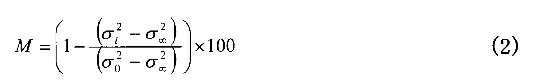
- the water dispersion ⁇ t at time t was defined by the following equation (1), and the water mixing degree M was calculated by the following (2).
- the sample particle diameter: x (mm) the moisture ratio in the sample with the particle diameter ⁇ : C (x) (mass%), the weight ratio of the sample with the particle diameter ⁇ : f (x) (mass%), number of samples: m (interval).
- the stirring conditions for achieving a mixing degree of 95% were arranged by uniform mixing time, peripheral speed, and scale of the stirring device.
- the uniform mixing time was determined from the change over time in the mixing degree.
- the scale of the stirring device used the diameter of the stirring vessel as a representative diameter. As a result of the analysis, it was found that the uniform mixing time is well organized at the peripheral speed regardless of the device diameter. Further, it was found that the uniform mixing time decreases as the moisture content of the raw material increases, and the uniform mixing time increases as the fine powder ratio in the raw material increases.
- the equipment row in the apparatus for producing a granulated raw material for sintering it is possible to uniformly disperse moisture and fine powder in the raw material and obtain uniform granulated particles having a uniform particle size distribution. Therefore, sintering is performed using the obtained granulation raw material for sintering, thereby improving the sinter strength and productivity through improvement of combustion efficiency and melt generation conditions. It is possible to obtain a technique capable of reducing the manufacturing cost and the amount of CO 2 generated from the blast furnace.
Landscapes
- Engineering & Computer Science (AREA)
- Chemical & Material Sciences (AREA)
- Manufacturing & Machinery (AREA)
- Geochemistry & Mineralogy (AREA)
- Geology (AREA)
- General Life Sciences & Earth Sciences (AREA)
- Life Sciences & Earth Sciences (AREA)
- Environmental & Geological Engineering (AREA)
- Materials Engineering (AREA)
- Mechanical Engineering (AREA)
- Metallurgy (AREA)
- Organic Chemistry (AREA)
- Manufacture And Refinement Of Metals (AREA)
Abstract
Description
特許文献2:特公平6-21297号公報
特許文献3:特公平6-21298号公報
特許文献4:特公平6-21299号公報
特許文献5:特公平6-60358号公報
まず、ペレットフィードなどの難造粒性の微粉鉄鉱石として、バナジウムを多く含む(40mass%)配合原料を使用して造粒した後、生成した造粒(擬似)粒子の粒度分布とペレットフィードの粒度分布を計測した。その結果を図2に示す。まず、図2(a)に示すように、配合原料中のペレットフィードを多量に含むと、ペレットフィードを含まない場合に比べて粗粒(8mm超)になる割合が高くなり、その重量割合は75mass%程度となることがわかった。また、造粒粒子中のペレットフィードの(粒度)分布(図2(b))も、造粒粒子の粒度分布と同様の傾向を示し、粗粒中のペレットフィードの割合が80mass%程度と高く、ペレットフィードの殆どが粗粒の部分に偏在していることがわかった。このことから、粗大な擬似粒子というのは、ペレットフィードどうしが凝集し合うことで形成さていることが確認できた。さらに、造粒した擬似粒子の水分量を測定したところ(図2(b))、粗粒領域における水分量が高いこともわかった。このことから、水分はペレットフィードが優先して吸収し、そのためにペレットフィードどうしで凝集し合って粗大な擬似粒子中に多く吸収されて偏在していると考えられる。
(1)前記焼結配合原料は、5~50mass%のペレットフィードやテーリング鉱である微粉鉄鉱石と、残部がシンターフィードである粉鉄鉱石の他、返鉱、珪石、石灰、生石灰の如き焼結原料であること、
(2)前記攪拌ほぐし機は、不均一に固化し粗粒化した焼結配合原料の解砕-分散に伴うほぐし機能をもつ解砕用高速攪拌機を用いること、
(3)前記解砕-分散に伴うほぐし機能は、ミキサー内で高速回転する攪拌羽根を用いることによって粒度と水分とを均一に分散させる機能であること、
(4)前記解砕-分散機能のための攪拌羽根の周速を、1~50m/sとすること、
(5)前記解砕-分散は、ペレタイザー内に滞留する配合原料転動層の表層部に面して配設されている解砕機にて行ない、該解砕機はペレタイザーの底面に対して垂直な方向に昇降可能であること、
が考えられる。
(2)また、本発明の焼結用造粒原料の製造装置における設備列によれば、焼結配合原料の攪拌混合時に微粉鉄鉱石や水分の均一分散を効果的に果すことができるので造粒時に使用されるバインダーの量を削減することができる。
(3)本発明によって製造された焼結用造粒原料をDL焼結機に用いると、これが装入されたときに原料堆積層の密度の低減を図ることができ、ひていは通気性の向上に伴う焼成時間の短縮ならびに焼結生産性の向上を図ることができる。
図5(a)~(d)はそれぞれ焼結用造粒原料の製造装置における設備列を比較するための図であり、(a)は従来例に係る設備列の一例を、(b)、(c)、(d)は本発明例に係る設備列の一例を、それぞれ示している。図5(a)に示す従来例に係る設備列の一例では、配合槽から切り出された鉄鉱石粉や副原料粉を、まず、混合工程としてドラムミキサー1にて混合し、次いで、混合後の配合原料を造粒工程としてパン型ペレタイザー2等の造粒機に送給して造粒処理する。なお、混合工程および造粒工程では、それぞれ1~2mass%程度の水添加が行なわれ、所定の造粒水分になるように加湿調整されて所定の擬似粒子が製造される。なお、図示の3は、粉コークスや副原料の外装用のドラムミキサーである。また、図3(a)、(b)は、焼結用造粒原料である擬似粒子の構造的特徴を模式図として示したものである。
本発明では、図5(a)に示す従来例のような、ドラムミキサーによる混合工程及びパンペレタイザーによる造粒工程からなる従来の焼結用造粒原料の製造装置の設備列に代えて、図5(b)に示す例では造粒機としてのミキサー12の前に、図5(c)および図5(d)に示す例では造粒機としての1次ミキサー13の前に、微粉鉄鉱石を含む焼結配合原料をまず、アイリッヒミキサーの如き高速攪拌機11を使って、該微粉鉄鉱石の均一分散(拡散)ならびに水分の均一分散処理を行っている。
以下、図5(b)~(d)における、第1のサンプラー(a1)および第2のサンプラー(a2)について説明する。

2 パン型ペレタイザー
3 ドラムミキサー
11 攪拌機
12 ミキサー
13 1次ミキサー
14 2次ミキサー
(a1) 第1のサンプラー
(a2) 第2のサンプラー
Claims (8)
- 微粉鉄鉱石を含有する焼結配合原料から焼結用造粒原料を製造する装置において:
被処理焼結配合原料中の微粉鉄鉱石および水分を均一に分散させる攪拌ほぐし機と;この攪拌ほぐし機の下流側に設けられ、攪拌ほぐし処理後の焼結配合原料をサンプリングして粒度分布および水分分布を求める第1の測定器と;この第1の測定器の下流側に設けられ、攪拌ほぐし処理後の焼結配合原料を水分添加の下で攪拌混合して造粒し、その後端から石灰粉および粉コークスを供給して、造粒後の焼結用造粒原料の粒子の表面に石灰粉と粉コークスを外装する造粒機と;この造粒機の下流側に設けられ、造粒、外装後の焼結用造粒原料をサンプリングして粒度分布および水分分布を求める第2の測定器と;を備え、
前記第1の測定器で求めた粒度分布および水分分布と前記第2の測定器で求めた粒度分布および水分分布とに基づき、前記攪拌ほぐし機の攪拌条件、攪拌ほぐし機への添加水の有無、造粒機での添加水分値を制御することを特徴とする焼結用造粒原料の製造装置。 - 微粉鉄鉱石を含有する焼結配合原料から焼結用造粒原料を製造する装置において:
被処理焼結配合原料中の微粉鉄鉱石および水分を均一に分散させる攪拌ほぐし機と;この攪拌ほぐし機の下流側に設けられ、攪拌ほぐし処理後の焼結配合原料をサンプリングして粒度分布および水分分布を求める第1の測定器と;この第1の測定器の下流側に設けられ、攪拌ほぐし処理後の焼結配合原料を水分添加の下で攪拌混合して造粒する第1の造粒機と;この第1の造粒機の下流側に設けられ、第1の造粒機により造粒された焼結用造粒原料をさらに造粒し、その後端から石灰粉および粉コークスを供給して、造粒後の焼結用造粒原料の粒子の表面に石灰粉と粉コークスを外装する第2の造粒機と;この第2の造粒機の下流側に設けられ、造粒、外装後の焼結用造粒原料をサンプリングして粒度分布および水分分布を求める第2の測定器と;を備え、
前記第1の測定器で求めた粒度分布および水分分布と前記第2の測定器で求めた粒度分布および水分分布とに基づき、前記攪拌ほぐし機の攪拌条件、攪拌ほぐし機への添加水の有無、第1の造粒機での添加水分値を制御することを特徴とする焼結用造粒原料の製造装置。 - 微粉鉄鉱石を含有する焼結配合原料から焼結用造粒原料を製造する装置において:
被処理焼結配合原料中の微粉鉄鉱石および水分を均一に分散させる攪拌ほぐし機と;この攪拌ほぐし機の下流側に設けられ、攪拌ほぐし処理後の焼結配合原料をサンプリングして粒度分布および水分分布を求める第1の測定器と;この第1の測定器の下流側に設けられ、攪拌ほぐし処理後の焼結配合原料を水分添加の下で攪拌混合して造粒する第1の造粒機と;この第1の造粒機の下流側に設けられ、第1の造粒機で造粒後の焼結用造粒原料を水分とともに転動造粒するペレタイザーと;このペレタイザーの下流側に設けられ、転動造粒後の焼結用造粒原料をさらに造粒し、その後端から粉コークスを供給して、造粒後の焼結用造粒原料の粒子の表面に粉コークスを外装する第2の造粒機と;この第2の造粒機の下流側に設けられ、造粒、外装後の焼結用造粒原料をサンプリングして粒度分布および水分分布を求める第2の測定器と;を備え、
前記第1の測定器で求めた粒度分布および水分分布と前記第2の測定器で求めた粒度分布および水分分布とに基づき、前記攪拌ほぐし機の攪拌条件、攪拌ほぐし機への添加水の有無、第1の造粒機での添加水分値を制御することを特徴とする焼結用造粒原料の製造装置。 - 前記焼結配合原料は、5~50mass%のペレットフィードやテーリング鉱である微粉鉄鉱石と、残部がシンターフィードである粉鉄鉱石の他、返鉱、珪石、石灰、生石灰の如き焼結原料であることを特徴とする請求項1~3のいずれか1項に記載の焼結用造粒原料の製造装置。
- 前記攪拌ほぐし機は、不均一に固化し粗粒化した焼結配合原料の解砕-分散に伴うほぐし機能をもつ解砕用高速攪拌機を用いることを特徴とする請求項1~4のいずれか1項に記載の焼結用造粒原料の製造装置。
- 前記解砕-分散に伴うほぐし機能は、ミキサー内で高速回転する攪拌羽根を用いることによって粒度と水分とを均一に分散させる機能であることを特徴とする請求項1~5いずれか1に記載の焼結用造粒原料の製造装置。
- 前記解砕―分散機能のための攪拌羽根の周速を、1~50m/sとすることを特徴とする請求項1~6のいずれか1項に記載の焼結用造粒原料の製造装置。
- 前記解砕-分散は、ペレタイザー内に滞留する配合原料転動層の表層部に面して配設されている解砕機にて行ない、該解砕機はペレタイザーの底面に対して垂直な方向に昇降可能であることを特徴とする請求項3~7のいずれか1項に記載の焼結用造粒原料の製造装置。
Priority Applications (3)
| Application Number | Priority Date | Filing Date | Title |
|---|---|---|---|
| JP2015529951A JP5846402B1 (ja) | 2014-04-01 | 2015-03-30 | 焼結用造粒原料の製造装置 |
| TR2016/13592T TR201613592T1 (tr) | 2014-04-01 | 2015-03-30 | Sinter için ham granüle malzeme üretim cihazı. |
| PH12016501874A PH12016501874A1 (en) | 2014-04-01 | 2016-09-22 | Apparatus for manufacturing raw granulated material for sinter |
Applications Claiming Priority (2)
| Application Number | Priority Date | Filing Date | Title |
|---|---|---|---|
| JP2014075336 | 2014-04-01 | ||
| JP2014-075336 | 2014-04-01 |
Publications (1)
| Publication Number | Publication Date |
|---|---|
| WO2015152109A1 true WO2015152109A1 (ja) | 2015-10-08 |
Family
ID=54240432
Family Applications (1)
| Application Number | Title | Priority Date | Filing Date |
|---|---|---|---|
| PCT/JP2015/059836 WO2015152109A1 (ja) | 2014-04-01 | 2015-03-30 | 焼結用造粒原料の製造装置 |
Country Status (4)
| Country | Link |
|---|---|
| JP (1) | JP5846402B1 (ja) |
| PH (1) | PH12016501874A1 (ja) |
| TR (1) | TR201613592T1 (ja) |
| WO (1) | WO2015152109A1 (ja) |
Cited By (1)
| Publication number | Priority date | Publication date | Assignee | Title |
|---|---|---|---|---|
| CN106886818A (zh) * | 2015-12-16 | 2017-06-23 | 鞍钢股份有限公司 | 一种烧结混合料水分大小判定方法 |
Families Citing this family (1)
| Publication number | Priority date | Publication date | Assignee | Title |
|---|---|---|---|---|
| BR112018067367B1 (pt) * | 2016-03-04 | 2022-05-03 | Jfe Steel Corporation | Método para fabricar minério sinterizado |
Citations (2)
| Publication number | Priority date | Publication date | Assignee | Title |
|---|---|---|---|---|
| JPH1161281A (ja) * | 1997-08-07 | 1999-03-05 | Sumitomo Metal Ind Ltd | 焼結原料の造粒方法 |
| JP2013204058A (ja) * | 2012-03-27 | 2013-10-07 | Jfe Steel Corp | 焼結鉱製造用擬似粒子の製造方法および焼結鉱の製造方法 |
-
2015
- 2015-03-30 JP JP2015529951A patent/JP5846402B1/ja active Active
- 2015-03-30 TR TR2016/13592T patent/TR201613592T1/tr unknown
- 2015-03-30 WO PCT/JP2015/059836 patent/WO2015152109A1/ja active Application Filing
-
2016
- 2016-09-22 PH PH12016501874A patent/PH12016501874A1/en unknown
Patent Citations (2)
| Publication number | Priority date | Publication date | Assignee | Title |
|---|---|---|---|---|
| JPH1161281A (ja) * | 1997-08-07 | 1999-03-05 | Sumitomo Metal Ind Ltd | 焼結原料の造粒方法 |
| JP2013204058A (ja) * | 2012-03-27 | 2013-10-07 | Jfe Steel Corp | 焼結鉱製造用擬似粒子の製造方法および焼結鉱の製造方法 |
Cited By (2)
| Publication number | Priority date | Publication date | Assignee | Title |
|---|---|---|---|---|
| CN106886818A (zh) * | 2015-12-16 | 2017-06-23 | 鞍钢股份有限公司 | 一种烧结混合料水分大小判定方法 |
| CN106886818B (zh) * | 2015-12-16 | 2020-09-01 | 鞍钢股份有限公司 | 一种烧结混合料水分大小判定方法 |
Also Published As
| Publication number | Publication date |
|---|---|
| TR201613592T1 (tr) | 2017-02-21 |
| JP5846402B1 (ja) | 2016-01-20 |
| PH12016501874A1 (en) | 2017-01-09 |
| JPWO2015152109A1 (ja) | 2017-04-13 |
Similar Documents
| Publication | Publication Date | Title |
|---|---|---|
| JP3902629B2 (ja) | 焼結原料の事前処理方法 | |
| JP6508500B2 (ja) | 焼結鉱の製造方法 | |
| JP6132114B2 (ja) | 焼結用造粒原料の製造方法 | |
| JP2007247020A (ja) | 微粉原料の混練方法 | |
| JP5846402B1 (ja) | 焼結用造粒原料の製造装置 | |
| JP6256728B2 (ja) | 焼結用造粒原料の製造装置 | |
| TWI596213B (zh) | Sinter manufacturing method | |
| JP2007077512A (ja) | 焼結原料の事前処理方法 | |
| JP4786760B2 (ja) | 焼結原料の事前処理方法 | |
| JP6468367B2 (ja) | 焼結鉱の製造方法 | |
| JP4154914B2 (ja) | 高炉用焼結鉱の製造方法 | |
| JP2014234545A (ja) | 焼結用造粒原料の製造方法 | |
| JP6020823B2 (ja) | 焼結用造粒原料の製造方法 | |
| JP2006312786A (ja) | 焼結原料の事前処理方法 | |
| JP6954236B2 (ja) | 炭材内装焼結鉱の製造方法及び製造設備 | |
| JP5979382B2 (ja) | 焼結用造粒原料の製造方法およびその製造設備 | |
| WO2023233871A1 (ja) | 焼結用造粒原料の製造方法および焼結鉱の製造方法 | |
| JP2009287122A (ja) | 微粉原料の造粒方法 | |
| JPH06179928A (ja) | 焼結原料の事前処理方法 | |
| JP2020015962A (ja) | 焼結用原料の造粒方法 | |
| JPS5932532B2 (ja) | 焼結原料の事前処理方法 | |
| JPH08295952A (ja) | 焼結原料の事前処理方法 | |
| JP2007262454A (ja) | 微粉原料の造粒方法 |
Legal Events
| Date | Code | Title | Description |
|---|---|---|---|
| ENP | Entry into the national phase |
Ref document number: 2015529951 Country of ref document: JP Kind code of ref document: A |
|
| 121 | Ep: the epo has been informed by wipo that ep was designated in this application |
Ref document number: 15772584 Country of ref document: EP Kind code of ref document: A1 |
|
| WWE | Wipo information: entry into national phase |
Ref document number: 12016501874 Country of ref document: PH |
|
| WWE | Wipo information: entry into national phase |
Ref document number: 2016/13592 Country of ref document: TR |
|
| NENP | Non-entry into the national phase |
Ref country code: DE |
|
| 122 | Ep: pct application non-entry in european phase |
Ref document number: 15772584 Country of ref document: EP Kind code of ref document: A1 |