WO2015146933A1 - ピストン - Google Patents
ピストン Download PDFInfo
- Publication number
- WO2015146933A1 WO2015146933A1 PCT/JP2015/058790 JP2015058790W WO2015146933A1 WO 2015146933 A1 WO2015146933 A1 WO 2015146933A1 JP 2015058790 W JP2015058790 W JP 2015058790W WO 2015146933 A1 WO2015146933 A1 WO 2015146933A1
- Authority
- WO
- WIPO (PCT)
- Prior art keywords
- air
- piston
- valve recess
- chamber
- recess
- Prior art date
- Legal status (The legal status is an assumption and is not a legal conclusion. Google has not performed a legal analysis and makes no representation as to the accuracy of the status listed.)
- Ceased
Links
Images






Classifications
-
- F—MECHANICAL ENGINEERING; LIGHTING; HEATING; WEAPONS; BLASTING
- F02—COMBUSTION ENGINES; HOT-GAS OR COMBUSTION-PRODUCT ENGINE PLANTS
- F02B—INTERNAL-COMBUSTION PISTON ENGINES; COMBUSTION ENGINES IN GENERAL
- F02B23/00—Other engines characterised by special shape or construction of combustion chambers to improve operation
- F02B23/02—Other engines characterised by special shape or construction of combustion chambers to improve operation with compression ignition
- F02B23/06—Other engines characterised by special shape or construction of combustion chambers to improve operation with compression ignition the combustion space being arranged in working piston
- F02B23/0672—Omega-piston bowl, i.e. the combustion space having a central projection pointing towards the cylinder head and the surrounding wall being inclined towards the cylinder center axis
-
- F—MECHANICAL ENGINEERING; LIGHTING; HEATING; WEAPONS; BLASTING
- F02—COMBUSTION ENGINES; HOT-GAS OR COMBUSTION-PRODUCT ENGINE PLANTS
- F02B—INTERNAL-COMBUSTION PISTON ENGINES; COMBUSTION ENGINES IN GENERAL
- F02B31/00—Modifying induction systems for imparting a rotation to the charge in the cylinder
- F02B31/08—Modifying induction systems for imparting a rotation to the charge in the cylinder having multiple air inlets
- F02B31/085—Modifying induction systems for imparting a rotation to the charge in the cylinder having multiple air inlets having two inlet valves
-
- F—MECHANICAL ENGINEERING; LIGHTING; HEATING; WEAPONS; BLASTING
- F02—COMBUSTION ENGINES; HOT-GAS OR COMBUSTION-PRODUCT ENGINE PLANTS
- F02B—INTERNAL-COMBUSTION PISTON ENGINES; COMBUSTION ENGINES IN GENERAL
- F02B23/00—Other engines characterised by special shape or construction of combustion chambers to improve operation
- F02B23/02—Other engines characterised by special shape or construction of combustion chambers to improve operation with compression ignition
- F02B23/06—Other engines characterised by special shape or construction of combustion chambers to improve operation with compression ignition the combustion space being arranged in working piston
- F02B23/0618—Other engines characterised by special shape or construction of combustion chambers to improve operation with compression ignition the combustion space being arranged in working piston having in-cylinder means to influence the charge motion
- F02B23/0624—Swirl flow
-
- F—MECHANICAL ENGINEERING; LIGHTING; HEATING; WEAPONS; BLASTING
- F02—COMBUSTION ENGINES; HOT-GAS OR COMBUSTION-PRODUCT ENGINE PLANTS
- F02B—INTERNAL-COMBUSTION PISTON ENGINES; COMBUSTION ENGINES IN GENERAL
- F02B23/00—Other engines characterised by special shape or construction of combustion chambers to improve operation
- F02B23/02—Other engines characterised by special shape or construction of combustion chambers to improve operation with compression ignition
- F02B23/06—Other engines characterised by special shape or construction of combustion chambers to improve operation with compression ignition the combustion space being arranged in working piston
- F02B23/0618—Other engines characterised by special shape or construction of combustion chambers to improve operation with compression ignition the combustion space being arranged in working piston having in-cylinder means to influence the charge motion
- F02B23/0627—Other engines characterised by special shape or construction of combustion chambers to improve operation with compression ignition the combustion space being arranged in working piston having in-cylinder means to influence the charge motion having additional bores or grooves machined into the piston for guiding air or charge flow to the piston bowl
-
- Y—GENERAL TAGGING OF NEW TECHNOLOGICAL DEVELOPMENTS; GENERAL TAGGING OF CROSS-SECTIONAL TECHNOLOGIES SPANNING OVER SEVERAL SECTIONS OF THE IPC; TECHNICAL SUBJECTS COVERED BY FORMER USPC CROSS-REFERENCE ART COLLECTIONS [XRACs] AND DIGESTS
- Y02—TECHNOLOGIES OR APPLICATIONS FOR MITIGATION OR ADAPTATION AGAINST CLIMATE CHANGE
- Y02T—CLIMATE CHANGE MITIGATION TECHNOLOGIES RELATED TO TRANSPORTATION
- Y02T10/00—Road transport of goods or passengers
- Y02T10/10—Internal combustion engine [ICE] based vehicles
- Y02T10/12—Improving ICE efficiencies
Definitions
- the present invention relates to piston technology.
- a diesel engine that injects fuel into a chamber formed in a piston is known (generally referred to as a direct injection diesel engine: see, for example, Patent Document 1).
- a diesel engine is used not only as a power source for vehicles and generators but also as a power source for ships.
- the object of the present invention is to provide a technology capable of preventing the accumulation of air in a valve recess, suppressing incomplete combustion, and reducing environmental load substances contained in exhaust gas.
- the first aspect of the present invention is: A chamber; In a piston formed with a valve recess that partially overlaps the chamber, An air lamp is provided around the bulb recess, The air lamp guides air that has flowed into the valve recess to the outside of the valve recess.
- the air lamp is provided on the downstream side of the valve recess with respect to the flow direction of the swirl flow.
- a third aspect of the present invention is the piston according to the second aspect,
- the air lamp is provided in an arc shape with reference to a point on an imaginary line passing through the center of the valve recess from the center of the chamber.
- the air lamp is provided in an arc shape with the center of the bulb recess as a reference.
- the air lamp is provided in an arc shape with respect to a point on the inner side of the center of the bulb recess.
- the air lamp is provided in an arc shape with reference to a point outside the center of the bulb recess.
- the air lamp is provided around the bulb recess.
- the air lamp guides the air flowing into the valve recess to the outside of the valve recess.
- the piston according to the present embodiment can prevent air from staying in the valve recess. Therefore, incomplete combustion in the valve recess can be suppressed. As a result, it is possible to reduce environmentally hazardous substances contained in the exhaust.
- the air lamp is provided downstream of the valve recess with respect to the flow direction of the swirl flow.
- the air lamp is provided in an arc shape with reference to a point on an imaginary line passing through the center of the valve recess from the center of the chamber.
- the air lamp is provided in an arc shape with the center of the bulb recess as a reference.
- the piston according to the present embodiment can evenly guide the air flowing into the valve recess to the outside of the valve recess, thereby preventing the swirl flow from being disturbed.
- the air lamp is provided in an arc shape with respect to a point that is inside the center of the bulb recess.
- the piston according to the present embodiment can prevent quenching and dilution of air (including combustion gas and flame) flowing out from the chamber, and suppress incomplete combustion outside the chamber.
- the air lamp is provided in an arc shape with reference to a point outside the center of the bulb recess.
- the piston which concerns on this embodiment can accelerate
- A The top view of the piston which concerns on 3rd embodiment.
- B The enlarged view of the piston which concerns on 3rd embodiment.
- C Sectional drawing of the piston which concerns on 3rd embodiment.
- the piston according to the invention of the present application is used for a diesel engine.
- the technical idea of the invention can be applied not only to a piston of a diesel engine but also to a piston of a gasoline engine or the like.
- FIG. 1 shows the structure of the diesel engine 100.
- the diesel engine 100 mainly includes a main body 1, an intake passage portion 2, an exhaust passage portion 3, and a fuel supply portion 4.
- Main part 1 converts thermal energy obtained by burning fuel into kinetic energy. Specifically, the thermal energy obtained by burning the fuel is converted into the rotational motion of the crankshaft 14.
- the main body 1 is mainly composed of a cylinder block 11, a cylinder head 12, a piston 13, a crankshaft 14, and a camshaft 15.
- the main body 1 is operated by a cylinder 11c provided in the cylinder block 11, a piston 13 slidably accommodated in the cylinder 11c, and a cylinder head 12 disposed so as to face the piston 13
- a chamber W is configured (see FIG. 2). That is, the working chamber W refers to an internal space whose volume changes due to the sliding movement of the piston 13.
- the piston 13 is connected to the crankshaft 14 by a connecting rod, and the crankshaft 14 is rotated by sliding of the piston 13.
- the crankshaft 14 rotates the camshaft 15 via a plurality of gears.
- the intake passage section 2 guides air sucked from the outside to the working chamber W.
- the intake path portion 2 is mainly composed of a compressor wheel (not shown) and an intake manifold 21 along the direction in which air flows.
- the intake manifold 21 guides the air compressed by the compressor wheel to the working chamber W. Since the diesel engine 100 is a multi-cylinder engine provided with a plurality of working chambers W, the intake manifold 21 is formed so as to communicate with the intake ports 12Ip connected to the respective working chambers W. The diesel engine 100 has two intake ports 12Ip for one working chamber W. Therefore, the diesel engine 100 includes two intake valves 12Iv for one working chamber W.
- the exhaust path section 3 guides the exhaust discharged from the working chamber W to the outside.
- the exhaust path portion 3 is mainly composed of an exhaust manifold 31 and a turbine wheel (not shown) along the direction in which the exhaust flows.
- the exhaust manifold 31 guides the exhaust discharged from the working chamber W to the turbine wheel. Since the diesel engine 100 is a multi-cylinder engine provided with a plurality of working chambers W, the exhaust manifold 31 is formed so as to communicate with the exhaust ports 12Ep connected to the respective working chambers W. The diesel engine 100 has two exhaust ports 12Ep for one working chamber W. Therefore, the diesel engine 100 includes two exhaust valves 12Ev with respect to one working chamber W.
- the fuel supply unit 4 guides the fuel supplied from the fuel tank to the working chamber W.
- the fuel supply unit 4 mainly includes a fuel injection pump 41 and a fuel injection nozzle 42 along the direction in which the fuel flows.
- the fuel injection pump 41 sends fuel pressurized by the reciprocating motion of the plunger to the fuel injection nozzle 42. Since the diesel engine 100 is attached so that the fuel injection nozzle 42 penetrates the cylinder head 12, the fuel injection nozzle 42 injects fuel into the working chamber W.
- the diesel engine 100 constitutes a so-called common rail fuel injection system that can be appropriately changed to an injection pattern by transmitting an electric signal to the fuel injection nozzle 42. However, what is called a jerk type fuel injection system which does not have such a function may be used.
- FIG. 2 shows an operation mode of the diesel engine 100.
- the arrow Fa represents the air flow direction
- the arrow Fe represents the exhaust flow direction.
- the arrow Sp represents the sliding direction of the piston 13
- the arrow Rc represents the rotational direction of the crankshaft 14.
- FIG. 3 shows the piston 13.
- the diesel engine 100 is a four-cycle engine that completes the intake stroke, the compression stroke, the expansion stroke, and the exhaust stroke while the crankshaft 14 rotates twice.
- the intake stroke is a stroke in which air is sucked into the working chamber W by opening the intake valve 12Iv and sliding the piston 13 downward.
- the piston 13 slides using the moment of inertia of the flywheel 16 (see FIG. 1).
- the diesel engine 100 moves to the compression stroke.
- the air sucked into the working chamber W swirls along the wall surface of the cylinder 11c. This swirling air flow is referred to as a swirl flow Sw (see FIGS. 5 and 6).
- the compression stroke is a stroke in which the air in the working chamber W is compressed by closing the intake valve 12Iv and sliding the piston 13 upward.
- the piston 13 slides using the moment of inertia of the flywheel 16 (see FIG. 1).
- fuel is injected from the fuel injection nozzle 42 into the air that has been compressed to high temperature and pressure.
- the fuel is dispersed and evaporated in the working chamber W, and mixed with air to start combustion.
- the diesel engine 100 moves to the expansion stroke.
- the air flow flowing into the chamber 13c is referred to as a squish flow Sq (see FIG. 5).
- the air that has flowed into the chamber 13c swirls along the wall surface of the chamber 13c.
- the expansion stroke is a stroke in which the piston 13 is slid downward by heat energy and converted into kinetic energy.
- the piston 13 slides while being pushed by the expanded air (combustion gas).
- the sliding motion of the piston 13 is converted into the rotational motion of the crankshaft 14.
- the flywheel 16 (see FIG. 1) stores the kinetic energy of the crankshaft 14.
- the diesel engine 100 shifts to the exhaust stroke.
- the air flow flowing out from the chamber 13c is referred to as a reverse squish flow Sqr (see FIG. 6).
- the air that has flowed out of the chamber 13c swirls along the wall surface of the cylinder 11c.
- the exhaust stroke is a stroke in which the exhaust valve 12Ev is opened and the piston 13 is slid upward to push out air (combustion gas) in the working chamber W as exhaust.
- the piston 13 slides using the moment of inertia of the flywheel 16 (see FIG. 1).
- the diesel engine 100 again shifts to the intake stroke.
- the air (combustion gas) filled in the working chamber W is pushed out as exhaust gas while turning along the wall surface of the cylinder 11c.
- the diesel engine 100 is continuously operated by repeating the intake stroke, the compression stroke, the expansion stroke, and the exhaust stroke.
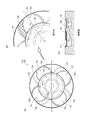
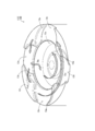
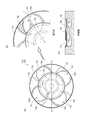
- FIG. 4 shows the piston 13A according to the first embodiment.
- FIG. 4A is a top view of the piston 13A.
- FIG. 4B is an enlarged view of the piston 13A.
- FIG. 4C is a cross-sectional view of the piston 13A.
- the piston 13A constitutes a working chamber W of the diesel engine 100.
- One chamber 13c and four valve recesses 13v are formed on the top surface 13t of the piston 13A.
- the chamber 13c indicates a recess formed for igniting and burning fuel.
- the chamber 13c has a conical protrusion 13cp at the center of its bottom surface. This is to smoothly swirl the air flowing into the chamber 13c (see FIG. 5).
- the chamber 13c has an annular projection 13cr at the upper end of its peripheral surface. In other words, the upper end of the peripheral surface of the chamber 13c is narrowed (such a chamber is called a reentrant type). This is to strengthen the flow of air flowing into the chamber 13c (squish flow Sq) and the flow of air flowing out of the chamber 13c (reverse squish flow Sqr) (see FIGS. 5 and 6).
- the valve recess 13v indicates a recess formed to avoid interference with the intake valve 12Iv and the exhaust valve 12Ev.
- the valve recess 13v has a cylindrical shape with a predetermined depth. This is to dodge the heads of the intake valve 12Iv and the exhaust valve 12Ev.
- the valve recess 13v partially overlaps the chamber 13c. That is, the valve recess 13v is connected to the chamber 13c. This is due to the shape (head size) of the intake valve 12Iv and the exhaust valve 12Ev.
- the piston 13A according to the present embodiment is provided with an air lamp 13a around the valve recess 13v (see the hatched portion in FIG. 4B). The role and effect of the air lamp 13a will be described below.
- FIG. 5 shows the flow of air in and around the chamber 13c during the compression stroke.
- FIG. 6 shows the air flow in and around the chamber 13c during the expansion stroke.
- the arrow in a figure represents the swirl flow Sw, the squish flow Sq, and the reverse squish flow Sqr.
- the air lamp 13a is a slope formed around the bulb recess 13v.
- the air lamp 13a gradually becomes deeper from the top surface 13t of the piston 13A and is connected to the valve recess 13v. That is, the air lamp 13a is an inclined surface connected to the valve recess 13v.
- the gradient of the air lamp 13a is 1/5, but it may be smaller.
- the particulate matter (PM) by these reduces remarkably in the operation area
- the organic soluble component (SOF) is reduced by 10% or more, and the effect is remarkable.
- the piston 13A is provided with the air lamp 13a around the valve recess 13v.
- the air lamp 13a guides the air flowing into the valve recess 13v to the outside of the valve recess 13v.
- the piston 13A according to the present embodiment can prevent air from staying in the valve recess 13v. Therefore, incomplete combustion in the valve recess 13v can be suppressed. As a result, it is possible to reduce environmentally hazardous substances contained in the exhaust.
- the air lamp 13a of the piston 13A is provided on the downstream side of the valve recess 13v with respect to the flow direction of the swirl flow Sw. The reason for this is based on the following design concept.
- the flow rate of the air flowing into the valve recess 13v becomes slow due to the expansion of the volume by the valve recess 13v. Further, the air flowing into the valve recess 13v is further slowed down under the influence of the squish flow Sq and the reverse squish flow Sqr. For this reason, an air lamp 13a is provided on the downstream side of the valve recess 13v to draw out the air in the valve recess 13v. That is, the air in the valve recess 13v, which has a slow speed, is gradually merged with the swirl flow Sw, which has a high speed, so that the air in the valve recess 13v is drawn out (see the arrow marked *). Thus, the piston 13A creates a forced air flow in the valve recess 13v.
- the air lamp 13a is provided on the downstream side of the valve recess 13v with respect to the flow direction of the swirl flow Sw.
- the piston 13A according to the present embodiment has an effect of drawing out the air in the valve recess 13v by the swirl flow Sw, so that the air can be prevented from staying in the valve recess 13v.
- the air lamp 13a of the piston 13A is provided in an arc shape with reference to the center Ca of the valve recess 13v (see FIG. 4B). The reason for this is based on the following design concept.
- the air lamp 13a has an arc shape so that the air spreads radially. That is, when the air that has flowed into the bulb recess 13v flows out along the air lamp 13a, the air is spread radially and merged with the swirl flow Sw. Further, since the air lamp 13a is provided in an arc shape with the center Ca of the bulb recess 13v as a reference, the flowing direction is not easily biased. Thus, the piston 13A prevents the swirl flow Sw formed above the valve recess 13v from being disturbed.
- the air lamp 13a is provided in an arc shape with the center Ca of the bulb recess 13v as a reference.
- the piston 13A according to the present embodiment can evenly guide the air flowing into the valve recess 13v to the outside of the valve recess 13v and prevent the swirl flow Sw from being disturbed.
- this piston 13 is referred to as “piston 13B”.
- FIG. 8 shows a piston 13B according to the second embodiment.
- FIG. 8A is a top view of the piston 13B.
- FIG. 8B is an enlarged view of the piston 13B.
- FIG. 8C is a cross-sectional view of the piston 13B.
- a single chamber 13c and four valve recesses 13v are formed on the top surface 13t of the piston 13B.
- the chamber 13c indicates a recess formed for igniting and burning fuel.
- the shape of the chamber 13c is the same as the piston 13A according to the first embodiment.
- valve recess 13v indicates a recess formed to avoid interference with the intake valve 12Iv and the exhaust valve 12Ev.
- the shape of the valve recess 13v is the same as the piston 13A according to the first embodiment.
- the piston 13B according to the present embodiment is also provided with an air lamp 13a around the valve recess 13v (see the hatched portion in FIG. 8B). The role and effect of the air lamp 13a will be described below.
- FIG. 9 shows the flow of air in and around the chamber 13c during the compression stroke.
- FIG. 10 shows the flow of air in and around the chamber 13c during the expansion stroke.
- the arrow in a figure represents the swirl flow Sw, the squish flow Sq, and the reverse squish flow Sqr.
- the air lamp 13a is a slope formed around the bulb recess 13v.
- the air lamp 13a gradually becomes deeper from the top surface 13t of the piston 13B and is connected to the valve recess 13v. That is, the air lamp 13a is an inclined surface connected to the valve recess 13v.
- the gradient of the air lamp 13a is 1/5, but it may be smaller.
- the swirl flow Sw is formed above the valve recess 13v also in the expansion stroke. Therefore, a part of the swirl flow Sw flows into the valve recess 13v and flows out along the air lamp 13a.
- a reverse squish flow Sqr is formed in the chamber 13c and the vicinity thereof.
- air including combustion gas and flame
- THC hydrocarbon components
- SOF organic soluble components
- the particulate matter (PM) by these reduces notably in the operation area
- the organic soluble component (SOF) is reduced by 10% or more, and the effect is remarkable.
- the piston 13B is provided with the air lamp 13a around the valve recess 13v.
- the air lamp 13a guides the air flowing into the valve recess 13v to the outside of the valve recess 13v.
- the piston 13B according to the present embodiment can prevent air from staying in the valve recess 13v. Therefore, incomplete combustion in the valve recess 13v can be suppressed. As a result, it is possible to reduce environmentally hazardous substances contained in the exhaust.
- the air lamp 13a of the piston 13B is provided on the downstream side of the valve recess 13v with respect to the flow direction of the swirl flow Sw.
- the reason for this is based on the following design concept.
- the flow rate of the air flowing into the valve recess 13v becomes slow due to the expansion of the volume by the valve recess 13v. Further, the air flowing into the valve recess 13v is further slowed down under the influence of the squish flow Sq and the reverse squish flow Sqr. For this reason, an air lamp 13a is provided on the downstream side of the valve recess 13v to draw out the air in the valve recess 13v. That is, the air in the valve recess 13v, which has a slow speed, is gradually merged with the swirl flow Sw, which has a high speed, so that the air in the valve recess 13v is drawn out (see the arrow marked *). Thus, the piston 13B creates a forced air flow in the valve recess 13v.
- the air lamp 13a is provided on the downstream side of the valve recess 13v with respect to the flow direction of the swirl flow Sw.
- the piston 13B according to the present embodiment has an effect of drawing out the air in the valve recess 13v by the swirl flow Sw, so that the air can be prevented from staying in the valve recess 13v.
- the air lamp 13a of the piston 13B is provided in an arc shape with reference to a point Cb that is inside the center Ca of the valve recess 13v (see FIG. 8B). The reason for this is based on the following design concept.
- the air lamp 13a has an arc shape so that the air spreads radially. That is, when the air that has flowed into the bulb recess 13v flows out along the air lamp 13a, the air is spread radially and merged with the swirl flow Sw. Further, since the air lamp 13a is provided in an arc shape with reference to a point Cb that is on the inner side of the center Ca of the bulb recess 13v, the flow direction tends to be slightly biased inward (for comparison, in the first embodiment). This shows the direction of flow of the piston 13A: see arrow Fad).
- the air lamp 13a is provided in a circular arc shape with the point Cb inside the center Ca of the bulb recess 13v as a reference.
- the piston 13B according to the present embodiment can prevent quenching and dilution of air (including combustion gas and flame) flowing out from the chamber 13c and suppress incomplete combustion outside the chamber 13c.
- piston 13C the piston 13 according to the third embodiment.
- the piston 13 is referred to as “piston 13C”.
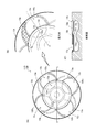
- FIG. 11 shows a piston 13C according to the third embodiment.
- FIG. 11A is a top view of the piston 13C.
- FIG. 11B is an enlarged view of the piston 13C.
- FIG. 11C is a cross-sectional view of the piston 13C.
- a single chamber 13c and four valve recesses 13v are formed on the top surface 13t of the piston 13C.
- the chamber 13c indicates a recess formed for igniting and burning fuel.
- the shape of the chamber 13c is the same as the piston 13A according to the first embodiment.
- valve recess 13v indicates a recess formed to avoid interference with the intake valve 12Iv and the exhaust valve 12Ev.
- the shape of the valve recess 13v is the same as the piston 13A according to the first embodiment.
- the piston 13C according to the present embodiment is also provided with an air lamp 13a around the valve recess 13v (see the hatched portion in FIG. 11B). The role and effect of the air lamp 13a will be described below.
- FIG. 12 shows the flow of air in and around the chamber 13c during the compression stroke.
- FIG. 13 shows the flow of air in and around the chamber 13c during the expansion stroke.
- the arrow in a figure represents the swirl flow Sw, the squish flow Sq, and the reverse squish flow Sqr.
- the air lamp 13a is a slope formed around the bulb recess 13v.
- the air lamp 13a gradually becomes deeper from the top surface 13t of the piston 13C and is connected to the valve recess 13v. That is, the air lamp 13a is an inclined surface connected to the valve recess 13v.
- the gradient of the air lamp 13a is 1/5, but it may be smaller.
- a swirl flow Sw is formed above the valve recess 13v. Therefore, a part of the swirl flow Sw flows into the valve recess 13v and flows out along the air lamp 13a. Therefore, air flows smoothly also inside the valve recess 13v.
- a squish flow Sq is formed in the chamber 13c and the vicinity thereof. At this time, air does not stay inside the valve recess 13v in the piston 13C, so that the air in the valve recess 13v does not easily flow into the chamber 13c all at once. Therefore, a substantially uniform squish flow Sq is formed in the circumferential direction of the chamber 13c.
- the swirl flow Sw is formed above the valve recess 13v also in the expansion stroke. Therefore, a part of the swirl flow Sw flows into the valve recess 13v and flows out along the air lamp 13a.
- a reverse squish flow Sqr is formed in the chamber 13c and the vicinity thereof.
- the piston 13C is less likely to cause incomplete combustion in the valve recess 13v. Therefore, hydrocarbon components (THC) and organic soluble components (SOF) due to incomplete combustion are hardly generated. Furthermore, it becomes difficult to generate a solid carbonized component (SOLID). And it is recognized that the particulate matter (PM) by these reduces notably in the operation area
- the piston 13C is provided with the air lamp 13a around the valve recess 13v.
- the air lamp 13a guides the air flowing into the valve recess 13v to the outside of the valve recess 13v.
- the piston 13C according to the present embodiment can prevent air from staying in the valve recess 13v. Therefore, incomplete combustion in the valve recess 13v can be suppressed. As a result, it is possible to reduce environmentally hazardous substances contained in the exhaust.
- the air lamp 13a of the piston 13C is provided on the downstream side of the valve recess 13v with respect to the flow direction of the swirl flow Sw.
- the reason for this is based on the following design concept.
- the flow rate of the air flowing into the valve recess 13v becomes slow due to the expansion of the volume by the valve recess 13v. Further, the air flowing into the valve recess 13v is further slowed down under the influence of the squish flow Sq and the reverse squish flow Sqr. For this reason, an air lamp 13a is provided on the downstream side of the valve recess 13v to draw out the air in the valve recess 13v. That is, the air in the valve recess 13v, which has a slow speed, is gradually merged with the swirl flow Sw, which has a high speed, so that the air in the valve recess 13v is drawn out (see the arrow marked *). Thus, the piston 13C creates a forced air flow in the valve recess 13v.
- the air lamp 13a is provided on the downstream side of the valve recess 13v with respect to the flow direction of the swirl flow Sw.
- the piston 13C according to the present embodiment has an effect of drawing out the air in the valve recess 13v by the swirl flow Sw, so that the air can be prevented from staying in the valve recess 13v.
- the air lamp 13a of the piston 13C is provided in an arc shape with reference to a point Cc that is outside the center Ca of the valve recess 13v (see FIG. 11B). The reason for this is based on the following design concept.
- the air lamp 13a has an arc shape so that the air spreads radially. That is, when the air that has flowed into the bulb recess 13v flows out along the air lamp 13a, the air is spread radially and merged with the swirl flow Sw. Further, since the air lamp 13a is provided in an arc shape with reference to a point Cc outside the center Ca of the bulb recess 13v, the flow direction tends to be slightly biased outward (for comparison, in the first embodiment). This shows the direction of flow of the piston 13A: see arrow Fad).
- the air lamp 13a is provided in an arc shape with the point Cc being outside the center Ca of the bulb recess 13v as a reference.
- the piston 13C according to the present embodiment can promote the mixing of the air (including combustion gas and flame) flowing out from the chamber 13c and the surrounding air, and can suppress incomplete combustion outside the chamber 13c. .
- Each piston 13 has a different reference position (center coordinate position) of the arc-shaped air lamp 13a. That is, the air lamp 13a of the piston 13A is provided in an arc shape with respect to the center Ca of the valve recess 13v, whereas the air lamp 13a of the piston 13B is based on the point Cb that is inside the center Ca of the valve recess 13v. It is provided in an arc shape.
- the air lamp 13a of the piston 13C is provided in an arc shape with reference to a point Cc that is outside the center Ca of the valve recess 13v.
- the air lamp 13a is provided in an arc shape with reference to a point on the imaginary line L passing from the center C of the chamber 13c to the center Ca of the valve recess 13v (see FIGS. 4, 8, and 11).
- the air lamp 13a is provided in an arc shape with a point on an imaginary line L passing from the center C of the chamber 13c to the center Ca of the bulb recess 13v as a reference.
- the piston 13 which concerns on this embodiment can change the aspect of the swirl flow Sw according to each characteristic of a diesel engine, and can adjust an exhaust characteristic.
- the present invention can be used for piston technology.
Landscapes
- Engineering & Computer Science (AREA)
- Chemical & Material Sciences (AREA)
- Combustion & Propulsion (AREA)
- Mechanical Engineering (AREA)
- General Engineering & Computer Science (AREA)
- Combustion Methods Of Internal-Combustion Engines (AREA)
Abstract
バルブリセス内における空気の滞留を防いで不完全燃焼を抑制し、排気に含まれる環境負荷物質を低減できる技術を提供する。即ち、チャンバー13cと、前記チャンバー13cに一部が重なるバルブリセス13vと、が形成されたピストン13において、前記バルブリセス13vの周囲にエアランプ13aが設けられ、前記エアランプ13aは、前記バルブリセス13vに流れ込んだ空気を該バルブリセス13v外へ案内する、とした。
Description
本発明は、ピストンの技術に関する。
従来より、ピストンに形成されたチャンバーへ燃料を噴射するディーゼルエンジンが知られている(一般的に直接噴射式ディーゼルエンジンという:例えば特許文献1参照)。このようなディーゼルエンジンは、車両や発電機の動力源として使用されるほか、船舶の動力源としても使用される。
ところで、ピストンには、吸気バルブや排気バルブとの干渉を避けるべく、バルブリセスが形成されたものが存在している(例えば特許文献2参照)。そのため、かかるピストンを備えるディーゼルエンジンは、バルブリセスに起因した不完全燃焼が発生し、排気に含まれる環境負荷物質が増加するという問題を有していた。つまり、バルブリセス内における空気の滞留によって局所的に不完全燃焼が発生し、排気に含まれる環境負荷物質が増加するという問題を有していたのである。
本発明は、バルブリセス内における空気の滞留を防いで不完全燃焼を抑制し、排気に含まれる環境負荷物質を低減できる技術を提供することを目的としている。
本発明の第一の態様は、
チャンバーと、
前記チャンバーに一部が重なるバルブリセスと、が形成されたピストンにおいて、
前記バルブリセスの周囲にエアランプが設けられ、
前記エアランプは、前記バルブリセスに流れ込んだ空気を該バルブリセス外へ案内する、としたものである。
チャンバーと、
前記チャンバーに一部が重なるバルブリセスと、が形成されたピストンにおいて、
前記バルブリセスの周囲にエアランプが設けられ、
前記エアランプは、前記バルブリセスに流れ込んだ空気を該バルブリセス外へ案内する、としたものである。
本発明の第二の態様は、第一の態様に係るピストンにおいて、
前記エアランプは、スワール流の流動方向に対して前記バルブリセスの下流側に設けられる、としたものである。
前記エアランプは、スワール流の流動方向に対して前記バルブリセスの下流側に設けられる、としたものである。
本発明の第三の態様は、第二の態様に係るピストンにおいて、
前記エアランプは、前記チャンバーの中心から前記バルブリセスの中心を通る仮想線上の点を基準として円弧状に設けられる、としたものである。
前記エアランプは、前記チャンバーの中心から前記バルブリセスの中心を通る仮想線上の点を基準として円弧状に設けられる、としたものである。
本発明の第四の態様は、第三の態様に係るピストンにおいて、
前記エアランプは、前記バルブリセスの中心を基準として円弧状に設けられる、としたものである。
前記エアランプは、前記バルブリセスの中心を基準として円弧状に設けられる、としたものである。
本発明の第五の態様は、第三の態様に係るピストンにおいて、
前記エアランプは、前記バルブリセスの中心よりも内側となる点を基準として円弧状に設けられる、としたものである。
前記エアランプは、前記バルブリセスの中心よりも内側となる点を基準として円弧状に設けられる、としたものである。
本発明の第六の態様は、第三の態様に係るピストンにおいて、
前記エアランプは、前記バルブリセスの中心よりも外側となる点を基準として円弧状に設けられる、としたものである。
前記エアランプは、前記バルブリセスの中心よりも外側となる点を基準として円弧状に設けられる、としたものである。
本発明の効果として、以下に示すような効果を奏する。
本発明の第一の態様によれば、バルブリセスの周囲にエアランプが設けられている。そして、エアランプは、バルブリセスに流れ込んだ空気を該バルブリセス外へ案内する。これにより、本実施形態に係るピストンは、バルブリセス内に空気が滞留するのを防ぐことができる。従って、バルブリセス内における不完全燃焼を抑制できる。ひいては、排気に含まれる環境負荷物質を低減させることが可能となる。
本発明の第二の態様によれば、エアランプは、スワール流の流動方向に対してバルブリセスの下流側に設けられる。これにより、本実施形態に係るピストンは、スワール流によってバルブリセス内の空気を引き出す効果が発生するので、バルブリセス内に空気が滞留するのを防ぐことができる。
本発明の第三の態様によれば、エアランプは、チャンバーの中心からバルブリセスの中心を通る仮想線上の点を基準として円弧状に設けられる。これにより、本実施形態に係るピストンは、ディーゼルエンジンの個々の特性に応じてスワール流の態様を変更し、排気特性を調節することができる。
本発明の第四の態様によれば、エアランプは、バルブリセスの中心を基準として円弧状に設けられる。これにより、本実施形態に係るピストンは、バルブリセスに流れ込んだ空気を該バルブリセス外へ均平に案内し、スワール流の乱れを防ぐことができる。
本発明の第五の態様によれば、エアランプは、バルブリセスの中心よりも内側となる点を基準として円弧状に設けられる。これにより、本実施形態に係るピストンは、チャンバーから流れ出した空気(燃焼ガスや火炎を含む)の急冷化や希薄化を防ぎ、チャンバー外における不完全燃焼を抑制することができる。
本発明の第六の態様によれば、エアランプは、バルブリセスの中心よりも外側となる点を基準として円弧状に設けられる。これにより、本実施形態に係るピストンは、チャンバーから流れ出した空気(燃焼ガスや火炎を含む)と周囲の空気との混合を早め、チャンバー外における不完全燃焼を抑制することができる。
本願の発明に係るピストンは、ディーゼルエンジンに用いられるものである。但し、かかる発明の技術的思想は、ディーゼルエンジンのピストンに限らず、ガソリンエンジンなどのピストンにも適用することが可能である。
まず、ディーゼルエンジン100について簡単に説明する。
図1は、ディーゼルエンジン100の構造を示している。
ディーゼルエンジン100は、主に主体部1と、吸気経路部2と、排気経路部3と、燃料供給部4と、で構成されている。
主体部1は、燃料を燃焼させて得た熱エネルギーを運動エネルギーに変換する。具体的には、燃料を燃焼させて得た熱エネルギーをクランクシャフト14の回転運動に変換する。主体部1は、主にシリンダブロック11と、シリンダヘッド12と、ピストン13と、クランクシャフト14と、カムシャフト15と、で構成される。
主体部1には、シリンダブロック11に設けられたシリンダ11cと、該シリンダ11cに摺動自在に収納されたピストン13と、該ピストン13に対向するように配置されたシリンダヘッド12と、で作動室Wが構成されている(図2参照)。つまり、作動室Wとは、ピストン13の摺動運動によって容積が変化する内部空間を指す。ピストン13は、コネクティングロッドによってクランクシャフト14と連結されており、該ピストン13の摺動によってクランクシャフト14を回転させる。また、クランクシャフト14は、複数のギヤを介してカムシャフト15を回転させる。
吸気経路部2は、外部から吸入された空気を作動室Wへ導く。吸気経路部2は、空気が流れる方向に沿って、主にコンプレッサホイル(図示せず)と、吸気マニホールド21と、で構成される。
吸気マニホールド21は、コンプレッサホイルによって圧縮された空気を作動室Wへ案内する。本ディーゼルエンジン100は複数の作動室Wが設けられた多気筒エンジンであるため、吸気マニホールド21は、各作動室Wにつながる吸気ポート12Ipと連通するように形成されている。なお、本ディーゼルエンジン100は、一の作動室Wに対して二つの吸気ポート12Ipを有している。そのため、本ディーゼルエンジン100は、一の作動室Wに対して二つの吸気バルブ12Ivを備えている。
排気経路部3は、作動室Wから排出された排気を外部へ導く。排気経路部3は、排気が流れる方向に沿って、主に排気マニホールド31と、タービンホイル(図示せず)と、で構成される。
排気マニホールド31は、作動室Wから排出された排気をタービンホイルへ案内する。本ディーゼルエンジン100は複数の作動室Wが設けられた多気筒エンジンであるため、排気マニホールド31は、各作動室Wにつながる排気ポート12Epと連通するように形成されている。なお、本ディーゼルエンジン100は、一の作動室Wに対して二つの排気ポート12Epを有している。そのため、本ディーゼルエンジン100は、一の作動室Wに対して二つの排気バルブ12Evを備えている。
燃料供給部4は、燃料タンクから供給された燃料を作動室Wへ導く。燃料供給部4は、燃料が流れる方向に沿って、主に燃料噴射ポンプ41と、燃料噴射ノズル42と、で構成される。
燃料噴射ポンプ41は、プランジャの往復運動によって加圧した燃料を燃料噴射ノズル42へ送り出す。本ディーゼルエンジン100は燃料噴射ノズル42がシリンダヘッド12を貫くように取り付けられているため、燃料噴射ノズル42は、作動室Wの内部に燃料を噴射する。なお、本ディーゼルエンジン100は、燃料噴射ノズル42に電気信号を送信することによって適宜に噴射パターンに変更できる、いわゆるコモンレール式燃料噴射システムを構成している。但し、そのような機能を有しない、いわゆるジャーク式燃料噴射システムを構成したものであっても良い。
次に、ディーゼルエンジン100の作動態様について簡単に説明する。
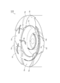
図2は、ディーゼルエンジン100の作動態様を示している。なお、矢印Faは、空気の流れ方向を表し、矢印Feは、排気の流れ方向を表す。矢印Spは、ピストン13の摺動方向を表し、矢印Rcは、クランクシャフト14の回転方向を表す。また、図3は、ピストン13を示している。
本ディーゼルエンジン100は、吸気行程、圧縮行程、膨張行程、排気行程の各行程をクランクシャフト14が二回転する間に完結する4サイクルエンジンである。
吸気行程は、吸気バルブ12Ivを開弁するとともにピストン13を下方へ摺動させて作動室W内に空気を吸い込む行程である。ピストン13は、フライホイル16(図1参照)の慣性モーメントを利用して摺動する。こうして、ディーゼルエンジン100は、圧縮行程へ移行する。なお、作動室W内に吸い込まれた空気は、シリンダ11cの壁面に沿って旋回する。この旋回する空気の流れをスワール流Swという(図5、6参照)。
圧縮行程は、吸気バルブ12Ivを閉弁するとともにピストン13を上方へ摺動させて作動室W内の空気を圧縮する行程である。ピストン13は、フライホイル16(図1参照)の慣性モーメントを利用して摺動する。その後、圧縮されて高温高圧となった空気中に燃料噴射ノズル42から燃料が噴射される。すると、燃料は、作動室W内で分散して蒸発し、空気と混合して燃焼を開始する。こうして、ディーゼルエンジン100は、膨張行程へ移行する。なお、圧縮行程において、チャンバー13cに流れ込む空気の流れをスキッシュ流Sqという(図5参照)。チャンバー13cに流れ込んだ空気は、チャンバー13cの壁面に沿って旋回する。
膨張行程は、熱エネルギーによってピストン13を下方へ摺動させて運動エネルギーに変換する行程である。ピストン13は、膨張した空気(燃焼ガス)に押されて摺動する。そして、ピストン13の摺動運動は、クランクシャフト14の回転運動に変換される。このとき、フライホイル16(図1参照)は、クランクシャフト14の運動エネルギーを蓄える。こうして、ディーゼルエンジン100は、排気行程へ移行する。なお、膨張行程において、チャンバー13cから流れ出す空気の流れを逆スキッシュ流Sqrという(図6参照)。チャンバー13cから流れ出した空気は、シリンダ11cの壁面に沿って旋回する。
排気行程は、排気バルブ12Evを開弁するとともにピストン13を上方へ摺動させて作動室W内の空気(燃焼ガス)を排気として押し出す行程である。ピストン13は、フライホイル16(図1参照)の慣性モーメントを利用して摺動する。こうして、ディーゼルエンジン100は、再び吸気行程へ移行する。なお、作動室W内に充満している空気(燃焼ガス)は、シリンダ11cの壁面に沿って旋回しながら排気として押し出される。
このように、ディーゼルエンジン100は、吸気行程、圧縮行程、膨張行程、排気行程の各行程を繰り返すことにより、連続して運転するのである。
次に、第一の実施形態に係るピストン13について詳細に説明する。ここでは、かかるピストン13を「ピストン13A」とする。
図4は、第一の実施形態に係るピストン13Aを示している。なお、図4(A)は、ピストン13Aの上面図である。図4(B)は、ピストン13Aの拡大図である。そして、図4(C)は、ピストン13Aの断面図である。
ピストン13Aは、ディーゼルエンジン100の作動室Wを構成する。ピストン13Aの頂面13tには、一つのチャンバー13cと四つのバルブリセス13vが形成されている。
チャンバー13cは、燃料を着火・燃焼させるために形成された窪みを指す。チャンバー13cは、その底面の中央に円錐形状の突起部13cpを有している。これは、チャンバー13cに流れ込んだ空気を円滑に旋回させるためである(図5参照)。また、チャンバー13cは、その周面の上端に円環形状の突起部13crを有している。つまり、チャンバー13cは、その周面の上端が窄まっているのである(このようなチャンバーをリエントラント型という)。これは、チャンバー13cに流れ込む空気の流れ(スキッシュ流Sq)やチャンバー13cから流れ出す空気の流れ(逆スキッシュ流Sqr)を強めるためである(図5、図6参照)。
バルブリセス13vは、吸気バルブ12Ivや排気バルブ12Evとの干渉を避けるために形成された窪みを指す。バルブリセス13vは、所定の深さの円筒形状となっている。これは、吸気バルブ12Ivや排気バルブ12Evのヘッドをかわすためである。また、バルブリセス13vは、その一部がチャンバー13cと重なっている。つまり、バルブリセス13vは、チャンバー13cにつながっているのである。これは、吸気バルブ12Ivや排気バルブ12Evの形状(ヘッドの大きさ)などによるものである。
加えて、本実施形態に係るピストン13Aは、バルブリセス13vの周囲にエアランプ13aが設けられている(図4(B)のハッチング部分参照)。以下に、エアランプ13aの役割と効果について説明する。
図5は、圧縮行程におけるチャンバー13c及びその近傍の空気の流れを示している。図6は、膨張行程におけるチャンバー13c及びその近傍の空気の流れを示している。なお、図中の矢印は、スワール流Sw、スキッシュ流Sq、及び逆スキッシュ流Sqrを表す。
エアランプ13aは、バルブリセス13vの周囲に形成されたスロープである。エアランプ13aは、ピストン13Aの頂面13tから徐々に深くなり、バルブリセス13vに接続している。つまり、エアランプ13aは、バルブリセス13vにつながる傾斜面である。なお、エアランプ13aのこう配は、1/5となっているが、これより小さくしてもよい。
図5に示すように、圧縮行程においては、スワール流Swがバルブリセス13vの上方に形成されている。そのため、スワール流Swの一部がバルブリセス13vに流れ込み、エアランプ13aに沿って流れ出す。従って、バルブリセス13vの内部においても、円滑に空気が流れているのである。また、圧縮行程においては、チャンバー13c及びその近傍でスキッシュ流Sqが形成される。このとき、本ピストン13Aは、バルブリセス13vの内部に空気が滞留しないので、該バルブリセス13v内の空気が一気にチャンバー13cに流れ込みにくくなる。そのため、チャンバー13cの周方向でほぼ均一なスキッシュ流Sqが形成されるのである。
更に、図6に示すように、膨張行程においても、スワール流Swがバルブリセス13vの上方に形成されている。そのため、スワール流Swの一部がバルブリセス13vに流れ込み、エアランプ13aに沿って流れ出す。また、膨張行程においては、チャンバー13c及びその近傍で逆スキッシュ流Sqrが形成される。このとき、本ピストン13Aは、バルブリセス13vの内部で空気(燃焼ガスや火炎を含む)が滞留しないので、該バルブリセス13v内で不完全燃焼が発生しにくくなる。従って、不完全燃焼による炭化水素成分(THC)や有機可溶成分(SOF)が発生しにくくなる。更に、固形炭化成分(SOLID)も発生しにくくなる。そして、これらによる粒子状物質(PM)は、ディーゼルエンジン100に掛かる負荷が大きい運転領域において、顕著に低減することが認められる(図7参照)。特に、有機可溶成分(SOF)については、10パーセント以上も低減し、その効果が著しい。
このように、本ピストン13Aは、バルブリセス13vの周囲にエアランプ13aが設けられている。そして、エアランプ13aは、バルブリセス13vに流れ込んだ空気を該バルブリセス13v外へ案内する。これにより、本実施形態に係るピストン13Aは、バルブリセス13v内に空気が滞留するのを防ぐことができる。従って、バルブリセス13v内における不完全燃焼を抑制できる。ひいては、排気に含まれる環境負荷物質を低減させることが可能となる。
ここで、本ピストン13Aの他の特徴点について説明する。
本ピストン13Aのエアランプ13aは、スワール流Swの流動方向に対してバルブリセス13vの下流側に設けられている。このようにした理由は、以下の設計思想に基づくものである。
即ち、バルブリセス13vに流れ込んだ空気は、該バルブリセス13vによる容積の拡大によって流速が遅くなる。また、バルブリセス13vに流れ込んだ空気は、スキッシュ流Sqや逆スキッシュ流Sqrの影響を受けて更に速度が遅くなる。このため、バルブリセス13vの下流側にエアランプ13aを設けることにより、該バルブリセス13v内の空気を引き出すようにした。つまり、速度が早いスワール流Swに速度が遅いバルブリセス13v内の空気を徐々に合流させることで、該バルブリセス13v内の空気を引き出すようにしたのである(*印の矢印参照)。こうして、本ピストン13Aは、バルブリセス13v内に強制的な空気の流れを作り出している。
このように、エアランプ13aは、スワール流Swの流動方向に対してバルブリセス13vの下流側に設けられている。これにより、本実施形態に係るピストン13Aは、スワール流Swによってバルブリセス13v内の空気を引き出す効果が発生するので、バルブリセス13v内に空気が滞留するのを防ぐことができる。
更に、本ピストン13Aのエアランプ13aは、バルブリセス13vの中心Caを基準として円弧状に設けられている(図4(B)参照)。このようにした理由は、以下の設計思想に基づくものである。
即ち、バルブリセス13vに流れ込んだ空気は、エアランプ13aに沿って流れ出す。このため、エアランプ13aを円弧状とすることにより、空気が放射状に広がるようにした。つまり、バルブリセス13vに流れ込んだ空気がエアランプ13aに沿って流れ出す際に、放射状に広がりながらスワール流Swに合流するようにしたのである。また、エアランプ13aは、バルブリセス13vの中心Caを基準として円弧状に設けられているので、流れ出す方向が偏りにくくなる。こうして、本ピストン13Aは、バルブリセス13vの上方に形成されているスワール流Swを乱さないようにしている。
このように、エアランプ13aは、バルブリセス13vの中心Caを基準として円弧状に設けられている。これにより、本実施形態に係るピストン13Aは、バルブリセス13vに流れ込んだ空気を該バルブリセス13v外へ均平に案内し、スワール流Swの乱れを防ぐことができる。
次に、第二の実施形態に係るピストン13について詳細に説明する。ここでは、かかるピストン13を「ピストン13B」とする。
図8は、第二の実施形態に係るピストン13Bを示している。なお、図8(A)は、ピストン13Bの上面図である。図8(B)は、ピストン13Bの拡大図である。そして、図8(C)は、ピストン13Bの断面図である。
本ピストン13Bの頂面13tには、一つのチャンバー13cと四つのバルブリセス13vが形成されている。
チャンバー13cは、燃料を着火・燃焼させるために形成された窪みを指す。チャンバー13cの形状は、第一の実施形態に係るピストン13Aと同じである。
バルブリセス13vは、吸気バルブ12Ivや排気バルブ12Evとの干渉を避けるために形成された窪みを指す。バルブリセス13vの形状は、第一の実施形態に係るピストン13Aと同じである。
加えて、本実施形態に係るピストン13Bも、バルブリセス13vの周囲にエアランプ13aが設けられている(図8(B)のハッチング部分参照)。以下に、エアランプ13aの役割と効果について説明する。
図9は、圧縮行程におけるチャンバー13c及びその近傍の空気の流れを示している。図10は、膨張行程におけるチャンバー13c及びその近傍の空気の流れを示している。なお、図中の矢印は、スワール流Sw、スキッシュ流Sq、及び逆スキッシュ流Sqrを表す。
エアランプ13aは、バルブリセス13vの周囲に形成されたスロープである。エアランプ13aは、ピストン13Bの頂面13tから徐々に深くなり、バルブリセス13vに接続している。つまり、エアランプ13aは、バルブリセス13vにつながる傾斜面である。なお、エアランプ13aのこう配は、1/5となっているが、これより小さくしてもよい。
図9に示すように、圧縮行程においては、スワール流Swがバルブリセス13vの上方に形成されている。そのため、スワール流Swの一部がバルブリセス13vに流れ込み、エアランプ13aに沿って流れ出す。従って、バルブリセス13vの内部においても、円滑に空気が流れているのである。また、圧縮行程においては、チャンバー13c及びその近傍でスキッシュ流Sqが形成される。このとき、本ピストン13Bは、バルブリセス13vの内部に空気が滞留しないので、該バルブリセス13v内の空気が一気にチャンバー13cに流れ込みにくくなる。そのため、チャンバー13cの周方向でほぼ均一なスキッシュ流Sqが形成されるのである。
更に、図10に示すように、膨張行程においても、スワール流Swがバルブリセス13vの上方に形成されている。そのため、スワール流Swの一部がバルブリセス13vに流れ込み、エアランプ13aに沿って流れ出す。また、膨張行程においては、チャンバー13c及びその近傍で逆スキッシュ流Sqrが形成される。このとき、本ピストン13Bは、バルブリセス13vの内部で空気(燃焼ガスや火炎を含む)が滞留しないので、該バルブリセス13v内で不完全燃焼が発生しにくくなる。従って、不完全燃焼による炭化水素成分(THC)や有機可溶成分(SOF)が発生しにくくなる。更に、固形炭化成分(SOLID)も発生しにくくなる。そして、これらによる粒子状物質(PM)は、ディーゼルエンジン100に掛かる負荷が大きい運転領域において、顕著に低減することが認められる。特に、有機可溶成分(SOF)については、10パーセント以上も低減し、その効果が著しい。
このように、本ピストン13Bは、バルブリセス13vの周囲にエアランプ13aが設けられている。そして、エアランプ13aは、バルブリセス13vに流れ込んだ空気を該バルブリセス13v外へ案内する。これにより、本実施形態に係るピストン13Bは、バルブリセス13v内に空気が滞留するのを防ぐことができる。従って、バルブリセス13v内における不完全燃焼を抑制できる。ひいては、排気に含まれる環境負荷物質を低減させることが可能となる。
ここで、本ピストン13Bの他の特徴点について説明する。
本ピストン13Bのエアランプ13aは、スワール流Swの流動方向に対してバルブリセス13vの下流側に設けられている。このようにした理由は、以下の設計思想に基づくものである。
即ち、バルブリセス13vに流れ込んだ空気は、該バルブリセス13vによる容積の拡大によって流速が遅くなる。また、バルブリセス13vに流れ込んだ空気は、スキッシュ流Sqや逆スキッシュ流Sqrの影響を受けて更に速度が遅くなる。このため、バルブリセス13vの下流側にエアランプ13aを設けることにより、該バルブリセス13v内の空気を引き出すようにした。つまり、速度が早いスワール流Swに速度が遅いバルブリセス13v内の空気を徐々に合流させることで、該バルブリセス13v内の空気を引き出すようにしたのである(*印の矢印参照)。こうして、本ピストン13Bは、バルブリセス13v内に強制的な空気の流れを作り出している。
このように、エアランプ13aは、スワール流Swの流動方向に対してバルブリセス13vの下流側に設けられている。これにより、本実施形態に係るピストン13Bは、スワール流Swによってバルブリセス13v内の空気を引き出す効果が発生するので、バルブリセス13v内に空気が滞留するのを防ぐことができる。
更に、本ピストン13Bのエアランプ13aは、バルブリセス13vの中心Caよりも内側となる点Cbを基準として円弧状に設けられている(図8(B)参照)。このようにした理由は、以下の設計思想に基づくものである。
即ち、バルブリセス13vに流れ込んだ空気は、エアランプ13aに沿って流れ出す。このため、エアランプ13aを円弧状とすることにより、空気が放射状に広がるようにした。つまり、バルブリセス13vに流れ込んだ空気がエアランプ13aに沿って流れ出す際に、放射状に広がりながらスワール流Swに合流するようにしたのである。また、エアランプ13aは、バルブリセス13vの中心Caよりも内側となる点Cbを基準として円弧状に設けられているので、流れ出す方向がやや内側に偏りやすくなる(比較のために第一の実施形態に係るピストン13Aの流動方向を示す:矢印Fad参照)。これは、膨張行程において、チャンバー13cから流れ出した空気(燃焼ガスや火炎を含む)が急速に拡散するのを防ぐという効果を奏する。こうして、本ピストン13Bは、バルブリセス13vの上方に形成されているスワール流Swを乱さないようにしつつ、チャンバー13cから流れ出した空気(燃焼ガスや火炎を含む)の急冷化や希薄化を抑えている。
このように、エアランプ13aは、バルブリセス13vの中心Caよりも内側となる点Cbを基準として円弧状に設けられている。これにより、本実施形態に係るピストン13Bは、チャンバー13cから流れ出した空気(燃焼ガスや火炎を含む)の急冷化や希薄化を防ぎ、チャンバー13c外における不完全燃焼を抑制することができる。
次に、第三の実施形態に係るピストン13について詳細に説明する。ここでは、かかるピストン13を「ピストン13C」とする。
図11は、第三の実施形態に係るピストン13Cを示している。なお、図11(A)は、ピストン13Cの上面図である。図11(B)は、ピストン13Cの拡大図である。そして、図11(C)は、ピストン13Cの断面図である。
本ピストン13Cの頂面13tには、一つのチャンバー13cと四つのバルブリセス13vが形成されている。
チャンバー13cは、燃料を着火・燃焼させるために形成された窪みを指す。チャンバー13cの形状は、第一の実施形態に係るピストン13Aと同じである。
バルブリセス13vは、吸気バルブ12Ivや排気バルブ12Evとの干渉を避けるために形成された窪みを指す。バルブリセス13vの形状は、第一の実施形態に係るピストン13Aと同じである。
加えて、本実施形態に係るピストン13Cも、バルブリセス13vの周囲にエアランプ13aが設けられている(図11(B)のハッチング部分参照)。以下に、エアランプ13aの役割と効果について説明する。
図12は、圧縮行程におけるチャンバー13c及びその近傍の空気の流れを示している。図13は、膨張行程におけるチャンバー13c及びその近傍の空気の流れを示している。なお、図中の矢印は、スワール流Sw、スキッシュ流Sq、及び逆スキッシュ流Sqrを表す。
エアランプ13aは、バルブリセス13vの周囲に形成されたスロープである。エアランプ13aは、ピストン13Cの頂面13tから徐々に深くなり、バルブリセス13vに接続している。つまり、エアランプ13aは、バルブリセス13vにつながる傾斜面である。なお、エアランプ13aのこう配は、1/5となっているが、これより小さくしてもよい。
図12に示すように、圧縮行程においては、スワール流Swがバルブリセス13vの上方に形成されている。そのため、スワール流Swの一部がバルブリセス13vに流れ込み、エアランプ13aに沿って流れ出す。従って、バルブリセス13vの内部においても、円滑に空気が流れているのである。また、圧縮行程においては、チャンバー13c及びその近傍でスキッシュ流Sqが形成される。このとき、本ピストン13Cは、バルブリセス13vの内部に空気が滞留しないので、該バルブリセス13v内の空気が一気にチャンバー13cに流れ込みにくくなる。そのため、チャンバー13cの周方向でほぼ均一なスキッシュ流Sqが形成されるのである。
更に、図13に示すように、膨張行程においても、スワール流Swがバルブリセス13vの上方に形成されている。そのため、スワール流Swの一部がバルブリセス13vに流れ込み、エアランプ13aに沿って流れ出す。また、膨張行程においては、チャンバー13c及びその近傍で逆スキッシュ流Sqrが形成される。このとき、本ピストン13Cは、バルブリセス13vの内部で空気(燃焼ガスや火炎を含む)が滞留しないので、該バルブリセス13v内で不完全燃焼が発生しにくくなる。従って、不完全燃焼による炭化水素成分(THC)や有機可溶成分(SOF)が発生しにくくなる。更に、固形炭化成分(SOLID)も発生しにくくなる。そして、これらによる粒子状物質(PM)は、ディーゼルエンジン100に掛かる負荷が大きい運転領域において、顕著に低減することが認められる。特に、有機可溶成分(SOF)については、10パーセント以上も低減し、その効果が著しい。
このように、本ピストン13Cは、バルブリセス13vの周囲にエアランプ13aが設けられている。そして、エアランプ13aは、バルブリセス13vに流れ込んだ空気を該バルブリセス13v外へ案内する。これにより、本実施形態に係るピストン13Cは、バルブリセス13v内に空気が滞留するのを防ぐことができる。従って、バルブリセス13v内における不完全燃焼を抑制できる。ひいては、排気に含まれる環境負荷物質を低減させることが可能となる。
ここで、本ピストン13Cの他の特徴点について説明する。
本ピストン13Cのエアランプ13aは、スワール流Swの流動方向に対してバルブリセス13vの下流側に設けられている。このようにした理由は、以下の設計思想に基づくものである。
即ち、バルブリセス13vに流れ込んだ空気は、該バルブリセス13vによる容積の拡大によって流速が遅くなる。また、バルブリセス13vに流れ込んだ空気は、スキッシュ流Sqや逆スキッシュ流Sqrの影響を受けて更に速度が遅くなる。このため、バルブリセス13vの下流側にエアランプ13aを設けることにより、該バルブリセス13v内の空気を引き出すようにした。つまり、速度が早いスワール流Swに速度が遅いバルブリセス13v内の空気を徐々に合流させることで、該バルブリセス13v内の空気を引き出すようにしたのである(*印の矢印参照)。こうして、本ピストン13Cは、バルブリセス13v内に強制的な空気の流れを作り出している。
このように、エアランプ13aは、スワール流Swの流動方向に対してバルブリセス13vの下流側に設けられている。これにより、本実施形態に係るピストン13Cは、スワール流Swによってバルブリセス13v内の空気を引き出す効果が発生するので、バルブリセス13v内に空気が滞留するのを防ぐことができる。
更に、本ピストン13Cのエアランプ13aは、バルブリセス13vの中心Caよりも外側となる点Ccを基準として円弧状に設けられている(図11(B)参照)。このようにした理由は、以下の設計思想に基づくものである。
即ち、バルブリセス13vに流れ込んだ空気は、エアランプ13aに沿って流れ出す。このため、エアランプ13aを円弧状とすることにより、空気が放射状に広がるようにした。つまり、バルブリセス13vに流れ込んだ空気がエアランプ13aに沿って流れ出す際に、放射状に広がりながらスワール流Swに合流するようにしたのである。また、エアランプ13aは、バルブリセス13vの中心Caよりも外側となる点Ccを基準として円弧状に設けられているので、流れ出す方向がやや外側に偏りやすくなる(比較のために第一の実施形態に係るピストン13Aの流動方向を示す:矢印Fad参照)。これは、膨張行程において、チャンバー13cから流れ出した空気(燃焼ガスや火炎を含む)が急速に拡散するのを進めるという効果を奏する。こうして、本ピストン13Cは、バルブリセス13vの上方に形成されているスワール流Swを乱さないようにしつつ、チャンバー13cから流れ出した空気(燃焼ガスや火炎を含む)と周囲の空気との混合を促進させ、チャンバー13c外における不完全燃焼を抑制することができる。
このように、エアランプ13aは、バルブリセス13vの中心Caよりも外側となる点Ccを基準として円弧状に設けられている。これにより、本実施形態に係るピストン13Cは、チャンバー13cから流れ出した空気(燃焼ガスや火炎を含む)と周囲の空気との混合を促進させ、チャンバー13c外における不完全燃焼を抑制することができる。
以上が、各実施形態に係るピストン13の説明である。各ピストン13は、円弧状としたエアランプ13aの基準位置(中心座標の位置)が異なる。つまり、ピストン13Aのエアランプ13aは、バルブリセス13vの中心Caを基準として円弧状に設けられているのに対し、ピストン13Bのエアランプ13aは、バルブリセス13vの中心Caよりも内側となる点Cbを基準として円弧状に設けられている。また、ピストン13Cのエアランプ13aは、バルブリセス13vの中心Caよりも外側となる点Ccを基準として円弧状に設けられている。このように、エアランプ13aは、チャンバー13cの中心Cからバルブリセス13vの中心Caを通る仮想線L上の点を基準として円弧状に設けられる(図4、図8、図11参照)。
このように、エアランプ13aは、チャンバー13cの中心Cからバルブリセス13vの中心Caを通る仮想線L上の点を基準として円弧状に設けられる。これにより、本実施形態に係るピストン13は、ディーゼルエンジンの個々の特性に応じてスワール流Swの態様を変更し、排気特性を調節することができる。
本発明は、ピストンの技術に利用可能である。
100 ディーゼルエンジン
1 主体部
13 ピストン
13A 第一の実施形態に係るピストン
13B 第二の実施形態に係るピストン
13C 第三の実施形態に係るピストン
13a エアランプ
13c チャンバー
13v バルブリセス
C チャンバーの中心
Ca バルブリセスの中心
Cb バルブリセスの中心よりも内側となる点
Cc バルブリセスの中心よりも外側となる点
Sw スワール流
Sq スキッシュ流
Sqr 逆スキッシュ流
1 主体部
13 ピストン
13A 第一の実施形態に係るピストン
13B 第二の実施形態に係るピストン
13C 第三の実施形態に係るピストン
13a エアランプ
13c チャンバー
13v バルブリセス
C チャンバーの中心
Ca バルブリセスの中心
Cb バルブリセスの中心よりも内側となる点
Cc バルブリセスの中心よりも外側となる点
Sw スワール流
Sq スキッシュ流
Sqr 逆スキッシュ流
Claims (6)
- チャンバーと、
前記チャンバーに一部が重なるバルブリセスと、が形成されたピストンにおいて、
前記バルブリセスの周囲にエアランプが設けられ、
前記エアランプは、前記バルブリセスに流れ込んだ空気を該バルブリセス外へ案内する、ことを特徴としたピストン。 - 前記エアランプは、スワール流の流動方向に対して前記バルブリセスの下流側に設けられる、ことを特徴とした請求項1に記載のピストン。
- 前記エアランプは、前記チャンバーの中心から前記バルブリセスの中心を通る仮想線上の点を基準として円弧状に設けられる、ことを特徴とした請求項2に記載のピストン。
- 前記エアランプは、前記バルブリセスの中心を基準として円弧状に設けられる、ことを特徴とした請求項3に記載のピストン。
- 前記エアランプは、前記バルブリセスの中心よりも内側となる点を基準として円弧状に設けられる、ことを特徴とした請求項3に記載のピストン。
- 前記エアランプは、前記バルブリセスの中心よりも外側となる点を基準として円弧状に設けられる、ことを特徴とした請求項3に記載のピストン。
Applications Claiming Priority (2)
| Application Number | Priority Date | Filing Date | Title |
|---|---|---|---|
| JP2014-062670 | 2014-03-25 | ||
| JP2014062670A JP2015183647A (ja) | 2014-03-25 | 2014-03-25 | ピストン |
Publications (1)
| Publication Number | Publication Date |
|---|---|
| WO2015146933A1 true WO2015146933A1 (ja) | 2015-10-01 |
Family
ID=54195446
Family Applications (1)
| Application Number | Title | Priority Date | Filing Date |
|---|---|---|---|
| PCT/JP2015/058790 Ceased WO2015146933A1 (ja) | 2014-03-25 | 2015-03-23 | ピストン |
Country Status (2)
| Country | Link |
|---|---|
| JP (1) | JP2015183647A (ja) |
| WO (1) | WO2015146933A1 (ja) |
Families Citing this family (1)
| Publication number | Priority date | Publication date | Assignee | Title |
|---|---|---|---|---|
| JP7143936B2 (ja) * | 2019-03-27 | 2022-09-29 | 三菱自動車工業株式会社 | 副室式内燃機関 |
Citations (4)
| Publication number | Priority date | Publication date | Assignee | Title |
|---|---|---|---|---|
| JPS5666025U (ja) * | 1979-10-25 | 1981-06-02 | ||
| JPS56127328U (ja) * | 1980-02-26 | 1981-09-28 | ||
| JPS59114419U (ja) * | 1983-01-20 | 1984-08-02 | 日産自動車株式会社 | 直噴式デイ−ゼル機関のピストン |
| JP2007270749A (ja) * | 2006-03-31 | 2007-10-18 | Toyota Motor Corp | 内燃機関 |
-
2014
- 2014-03-25 JP JP2014062670A patent/JP2015183647A/ja active Pending
-
2015
- 2015-03-23 WO PCT/JP2015/058790 patent/WO2015146933A1/ja not_active Ceased
Patent Citations (4)
| Publication number | Priority date | Publication date | Assignee | Title |
|---|---|---|---|---|
| JPS5666025U (ja) * | 1979-10-25 | 1981-06-02 | ||
| JPS56127328U (ja) * | 1980-02-26 | 1981-09-28 | ||
| JPS59114419U (ja) * | 1983-01-20 | 1984-08-02 | 日産自動車株式会社 | 直噴式デイ−ゼル機関のピストン |
| JP2007270749A (ja) * | 2006-03-31 | 2007-10-18 | Toyota Motor Corp | 内燃機関 |
Also Published As
| Publication number | Publication date |
|---|---|
| JP2015183647A (ja) | 2015-10-22 |
Similar Documents
| Publication | Publication Date | Title |
|---|---|---|
| RU2566205C2 (ru) | Поршень, у которого форма полости сгорания обеспечивает требуемое соотношение между эффективностью сгорания и составом выхлопа | |
| US9328693B2 (en) | Piston, engine and operating method for reduced production of particulate matter | |
| KR20050052996A (ko) | 연료 직접 분사식 디젤 엔진 | |
| US20150198070A1 (en) | Combustion system including a piston crown and fuel injector | |
| JP2013519835A (ja) | 燃焼エンジンシリンダ内で往復移動するように配置されたピストン | |
| US8683974B2 (en) | Piston | |
| JP2018193909A (ja) | 多段噴射式ディーゼルエンジン、およびこれを備えた機械装置ならびに多段噴射式ディーゼルエンジンの制御方法 | |
| KR101918378B1 (ko) | 내연 기관 및 이를 구비한 선박 | |
| JP2016211680A (ja) | クロスヘッド型エンジン | |
| US10024223B2 (en) | Two-stroke internal combustion engine | |
| JP2012189041A (ja) | ディーゼルエンジン | |
| KR101366424B1 (ko) | 직접 분사식 디젤엔진에서 탄소 미립자 저감을 위한 연소실 형상 | |
| US10731600B2 (en) | Piston with soot reducing piston bowl | |
| CN103982350B (zh) | 燃油喷射装置的针阀组件 | |
| JP2017155735A (ja) | クロスヘッド式内燃機関 | |
| WO2021006119A1 (ja) | 内燃機関のピストンおよび内燃機関 | |
| JP5711250B2 (ja) | 燃料噴射装置を備えるエンジン | |
| GB2554719A (en) | System for evacuating residual gases from pre-chamber of engine | |
| JP2015183647A (ja) | ピストン | |
| US20130319372A1 (en) | Internal Combustion Engine Having Piston Configured For Reduced Particulate Emissions, And Method | |
| US9194327B2 (en) | Cylinder liner with slots | |
| CN105019999B (zh) | 汽油机燃烧系统及汽油机燃油喷射方法 | |
| JP6144076B2 (ja) | レシプロ式内燃機関の駆動方法 | |
| CN206722922U (zh) | 一种直喷发动机活塞、发动机及汽车 | |
| CN203809182U (zh) | 燃油喷射装置的针阀组件 |
Legal Events
| Date | Code | Title | Description |
|---|---|---|---|
| 121 | Ep: the epo has been informed by wipo that ep was designated in this application |
Ref document number: 15769633 Country of ref document: EP Kind code of ref document: A1 |
|
| DPE1 | Request for preliminary examination filed after expiration of 19th month from priority date (pct application filed from 20040101) | ||
| NENP | Non-entry into the national phase |
Ref country code: DE |
|
| 122 | Ep: pct application non-entry in european phase |
Ref document number: 15769633 Country of ref document: EP Kind code of ref document: A1 |