WO2015146548A1 - Instrument chirurgical - Google Patents
Instrument chirurgical Download PDFInfo
- Publication number
- WO2015146548A1 WO2015146548A1 PCT/JP2015/056689 JP2015056689W WO2015146548A1 WO 2015146548 A1 WO2015146548 A1 WO 2015146548A1 JP 2015056689 W JP2015056689 W JP 2015056689W WO 2015146548 A1 WO2015146548 A1 WO 2015146548A1
- Authority
- WO
- WIPO (PCT)
- Prior art keywords
- jaw
- tissue
- surgical instrument
- wall surface
- staple
- Prior art date
Links
Images


Classifications
-
- A—HUMAN NECESSITIES
- A61—MEDICAL OR VETERINARY SCIENCE; HYGIENE
- A61B—DIAGNOSIS; SURGERY; IDENTIFICATION
- A61B17/00—Surgical instruments, devices or methods, e.g. tourniquets
- A61B17/00491—Surgical glue applicators
-
- A—HUMAN NECESSITIES
- A61—MEDICAL OR VETERINARY SCIENCE; HYGIENE
- A61B—DIAGNOSIS; SURGERY; IDENTIFICATION
- A61B17/00—Surgical instruments, devices or methods, e.g. tourniquets
- A61B17/068—Surgical staplers, e.g. containing multiple staples or clamps
- A61B17/072—Surgical staplers, e.g. containing multiple staples or clamps for applying a row of staples in a single action, e.g. the staples being applied simultaneously
- A61B17/07207—Surgical staplers, e.g. containing multiple staples or clamps for applying a row of staples in a single action, e.g. the staples being applied simultaneously the staples being applied sequentially
-
- A—HUMAN NECESSITIES
- A61—MEDICAL OR VETERINARY SCIENCE; HYGIENE
- A61B—DIAGNOSIS; SURGERY; IDENTIFICATION
- A61B17/00—Surgical instruments, devices or methods, e.g. tourniquets
- A61B17/068—Surgical staplers, e.g. containing multiple staples or clamps
- A61B17/072—Surgical staplers, e.g. containing multiple staples or clamps for applying a row of staples in a single action, e.g. the staples being applied simultaneously
- A61B17/07292—Reinforcements for staple line, e.g. pledgets
-
- A—HUMAN NECESSITIES
- A61—MEDICAL OR VETERINARY SCIENCE; HYGIENE
- A61B—DIAGNOSIS; SURGERY; IDENTIFICATION
- A61B17/00—Surgical instruments, devices or methods, e.g. tourniquets
- A61B17/068—Surgical staplers, e.g. containing multiple staples or clamps
- A61B17/072—Surgical staplers, e.g. containing multiple staples or clamps for applying a row of staples in a single action, e.g. the staples being applied simultaneously
- A61B2017/07214—Stapler heads
- A61B2017/07242—Stapler heads achieving different staple heights during the same shot, e.g. using an anvil anvil having different heights or staples of different sizes
Definitions
- the present invention relates to a surgical instrument.
- This application claims priority on March 28, 2014, based on Japanese Patent Application No. 2014-077037 filed in Japan, the contents of which are incorporated herein by reference.
- Patent Documents 1 to 3 each include a cartridge in which a plurality of staples are stored, a knife for cutting a living tissue, and an operation unit for driving the staple into the tissue and cutting the tissue with the knife.
- a surgical instrument is disclosed.
- Gripping forceps are used for the purpose of moving and holding the tissue in the course of performing surgical treatment on the tissue.
- a tissue is sutured and dissected using the surgical instruments described in Patent Documents 1 to 3 above
- a desired portion is grasped by grasping forceps when a plurality of times of suturing and separation are advanced. May be moved to a position.
- grasping forceps it is necessary to consider the possibility of causing tissue destruction in the grasped portion, suture failure in the grasped portion, or the like.
- the present invention has been made in view of the above-described circumstances, and an object of the present invention is to provide a surgical instrument that is unlikely to cause tissue destruction or suture failure due to a procedure following suturing and separation.
- the surgical instrument includes an insertion portion that can be inserted into a body, a first jaw and a second jaw that are provided at a distal end portion of the insertion portion and grip tissue, and the first jaw. And a suture part for suturing the tissue grasped by the second jaw, and the tissue is separated within a suture region sutured by the suture part among the tissues grasped by the first jaw and the second jaw.
- a cut-off portion that is connected to the tissue in the suture region by the suture portion, and at least outside the suture region after being connected to the tissue.
- a tow member having a locked portion that protrudes from the top.
- the first jaw is disposed in the linear groove portion provided on the first gripping surface of the first jaw and the separation portion. And a staple row having a plurality of staples that can be fired from the first jaw toward the second jaw around the groove portion, the pulling member being And a sheet-like tag attached to the first jaw so as to follow the first gripping surface and the groove and cover the plurality of staples.
- the groove portion includes a first wall surface and a second wall surface that intersect with the first gripping surface and are separated from each other, and the first wall surface and the second wall surface.
- the first holding portion has a first slit portion that holds the first piece between the first wall surface and the bottom surface. It may be.
- the second holding portion may include a second slit portion that holds the second piece between the second wall surface and the bottom surface.
- the traction member may include at least one of polyglycolic acid, polylactic acid, and a copolymer thereof.
- the locked portion is accommodated in at least one of the first jaw and the second jaw, and the locked portion is connected to the tissue. Then, when the tissue is cut off by the cut-off portion, the locked portion may be protruded outside the stitched region.
- tissue destruction and suture failure due to the procedure following suturing and separation are unlikely to occur.
- FIG. 1 It is a side view which shows the surgical instrument of 1st Embodiment of this invention. It is a fragmentary sectional view which shows the structure of the distal part of the surgical instrument. It is sectional drawing in the III-III line of FIG. It is a top view which shows the 1st holding surface of the 1st jaw of the surgical instrument. It is a perspective view which shows the action
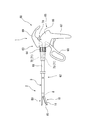
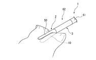
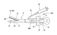
- FIG. 1 is a side view showing the surgical instrument of the present embodiment.
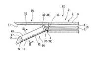
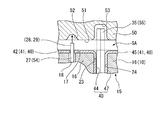
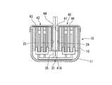
- FIG. 2 is a partial cross-sectional view showing the configuration of the distal portion of the surgical instrument.
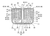
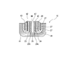
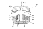
- 3 is a cross-sectional view taken along line III-III in FIG.
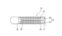
- FIG. 4 is a plan view showing a first gripping surface of the first jaw of the surgical instrument.
- FIG. 5 is a perspective view showing an operating part of the surgical instrument.
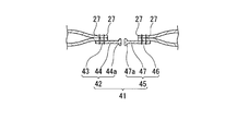
- 6 is a cross-sectional view showing a pulling member of the surgical instrument, and is an enlarged view of FIG.
- FIG. 7 is a view showing another attachment state of the pulling member.
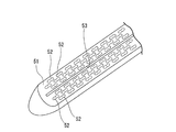
- FIG. 8 is a perspective view showing a second gripping surface of the second jaw of the surgical instrument.
- the surgical instrument 1 of the present embodiment shown in FIG. 1 is a medical instrument that stitches tissues together with staples 27 (see FIG. 12) and separates the stitched sites.
- the surgical instrument 1 has a cartridge 2 loaded with staples 27 and a stapler 60 to which the cartridge 2 can be attached.
- the cartridge 2 includes a shaft portion 3, an opening / closing link portion 8, a first jaw 10, and a second jaw 50.
- the shaft portion 3 is a substantially rod-shaped portion that can connect the cartridge 2 to the staple 27.
- the shaft portion 3 includes a tube portion 4 and a connection member 5.
- a connecting member 5 is disposed inside the cylindrical portion 4.
- the proximal end of the cylindrical portion 4 can be connected to a distal end of a shaft 61 described later of the stapler 60.
- the distal end of the cylindrical portion 4 is connected to the opening / closing link portion 8 and the second jaw 50.
- connection member 5 is a member that is operated by a user operation on the stapler 60.
- the connection member 5 includes a first connection member 6 for opening and closing the first jaw 10 with respect to the second jaw 50 and a second connection member 7 for operating an operation unit 31 described later.
- the proximal end of the first connection member 6 can be connected to the distal end of the first transmission member 72 in a transmission member 71 (see FIG. 1) described later.
- the distal end of the first connection member 6 is connected to the opening / closing link portion 8.
- the proximal end of the second connection member 7 can be connected to the distal end of the second transmission member 73 in the transmission member 71 (see FIG. 1) described later.
- a distal end of the second connection member 7 is connected to a proximal end of a base 32 described later.
- the opening / closing link portion 8 has a link structure that converts the movement of the first connecting member 6 in the central axis direction of the first connecting member 6 into the opening / closing movement of the first jaw 10.
- the first jaw 10 includes a base portion 11, a staple holder 15, a staple 27, an operating portion 31, and a pulling member 40.
- the base portion 11 has a substantially rod shape or channel having a longitudinal axis.
- the base portion 11 includes a recess 12 that can accommodate the staple holder 15 and the operating portion 31, and a communication path 13 to the shaft portion 3.
- the concave portion 12 is opened toward the second gripping surface 51 side of the second jaw 50.
- the communication path 13 to the shaft portion 3 is a path through which the second connection member 7 is inserted.
- the staple holder 15 has a holder body 16 and a driver 26.
- the holder body portion 16 is formed on the first gripping surface 17 that comes into contact with the tissue when gripping the tissue, the storage portion 18 in which the staple 27 is stored, and the first gripping surface 17. And an open groove 22.
- the holder body portion 16 is attached to the concave portion 12 of the base portion 11 so that the first gripping surface 17 is exposed from the base portion 11.
- the first gripping surface 17 is a surface directed to the second gripping surface 51 of the second jaw 50 in a state where the holder body portion 16 is attached to the concave portion 12 of the base portion 11.
- the accommodating portion 18 can accommodate the staple 27 in a state where the insertion end of the staple 27 is directed to the second gripping surface 51.
- the inner region of the envelope surrounding the plurality of accommodating portions 18 in the first gripping surface 17 defines a suture region SA (see FIG. 10) where the tissue is sutured by the staple 27.
- the staple rows 19 are respectively formed in the two regions divided by the groove portion 22.
- the first staple row 20 is composed of a plurality of staples 27 arranged in the direction in which the groove portion 22 extends.
- the first staple rows 20 are provided in two or more rows in a direction orthogonal to the direction in which the groove portion 22 extends and in a direction along the first gripping surface 17.
- the second staple row 21 is composed of a plurality of staples 27 arranged in the direction in which the groove portion 22 extends.
- two or more second staple rows 21 are provided in a direction orthogonal to the direction in which the groove portion 22 extends and in a direction along the first gripping surface 17.
- the staple row 19 has a plurality of staples 27 that can be fired from the first jaw 10 toward the second jaw 50 (see FIG. 11) around the groove portion 22.
- the groove portion 22 is a linear groove in which a later-described blade portion 35 of the operating portion 31 is accommodated so as to be able to advance and retract.
- the groove 22 is linear.
- the groove portion 22 defines a separation line L in tissue separation.
- the groove portion 22 includes a first wall surface 23 and a second wall surface 24 that are separated from each other, and a bottom surface 25 that connects the first wall surface 23 and the second wall surface 24.
- the bottom surface 25 of the groove portion 22 in the present embodiment is constituted by a part of the inner surface of the base portion 11.
- a gap is opened between the first wall surface 23 and the bottom surface 25 in order to allow the operating portion 31 to pass therethrough.
- the first wall surface 23 has a surface that intersects the first gripping surface 17 in the holder body portion 16.
- the first wall surface 23 extends from the first gripping surface 17 of the holder body portion 16 toward the bottom of the concave portion 12 of the base portion 11.
- the first wall surface 23 extends in the longitudinal axis direction of the base portion 11.
- the second wall surface 24 is formed in parallel (including substantially parallel) to the first wall surface 23 at a position away from the first wall surface 23 by a distance that allows the blade portion 35 of the operating portion 31 to pass. It is the surface.
- the second wall surface 24 is a surface that intersects the first gripping surface 17 in the holder body portion 16.
- the second wall surface 24 extends from the first gripping surface 17 of the holder body portion 16 toward the bottom of the concave portion 12 of the base portion 11.
- the second wall surface 24 extends in the longitudinal axis direction of the base portion 11.
- the driver 26 is disposed inside the accommodating portion 18.
- the driver 26 can be moved by the cam portion 33 of the operating portion 31 inside the accommodating portion 18. That is, when the driver 26 is moved by the cam portion 33 toward the opening on the first gripping surface 17 side in the housing portion 18, the driver 26 moves the connecting portion 30 of the staple 27 toward the opening on the first gripping surface 17 side. And pushes the staple 27 out of the container 18.
- the staple 27 includes a pair of leg portions 28 and 29 (see FIG. 12) in which insertion ends to be inserted into the tissue are formed, and a connecting portion 30 that connects the pair of leg portions 28 and 29 to each other.
- the staple 27 is formed into a U shape (a U shape in which all corners are perpendicular) by bending a deformable and highly biocompatible wire.
- a known structure may be appropriately selected and employed.
- the operating portion 31 includes a base 32, a cam portion 33, and a blade portion 35.
- the base 32 is connected to the distal end of the second connection member 7 in the connection member 5.
- the base 32 can be moved by moving the second connecting member 7 in the direction of the central axis thereof.
- a cam portion 33 and a blade portion 35 are attached to the base 32.
- the cam portion 33 has an inclined surface 34 that is inclined with respect to the longitudinal axis of the base portion 11.
- the inclined surface 34 of the cam portion 33 contacts the driver 26 and moves the driver 26 when the cam portion 33 moves in the longitudinal axis direction of the base portion 11.
- the moving direction of the cam portion 33 is a direction in which the groove portion 22 extends.
- the blade portion 35 is disposed on the proximal side of the cam portion 33.
- the blade part 35 has a sharp structure on the distal side capable of separating a living tissue.
- the blade portion 35 is disposed in the groove portion 22 so as to protrude from the first gripping surface 17 toward the second jaw 50 side.
- the protruding amount of the blade portion 35 from the first gripping surface 17 is such that the blade portion 35 does not catch on the second gripping surface 51 of the second jaw 50 when the first jaw 10 and the second jaw 50 are in a closed state.
- the amount of protrusion is about.
- the pulling member 40 is a member that can be connected to the tissue by the staple 27.
- the pulling member 40 includes a sheet-like tag 41 attached to the holder body 16 following the first gripping surface 17 and the groove 22.
- the tag 41 has a first piece 42 and a second piece 45.
- the first piece 42 is a staple in one of the regions of the first gripping surface 17 divided by the groove 22 and connected to the first wall surface 23 (that is, the region where the first staple row 20 is provided). 27 is covered.
- the second piece 45 is a staple in one of the regions of the first gripping surface 17 divided by the groove 22 and connected to the second wall surface 24 (that is, the region where the second staple row 21 is provided). 27 and a second piece 45 covering 27.
- the first piece 42 of the tag 41 extends from the first gripping surface 17 along the first wall surface 23 and is attached to the first wall surface 23 by, for example, adhesion.
- the first piece 42 is a first holding part 23a, which is an adhesive portion between the first piece 42 and the first wall surface 23, in the process of separating the first jaw 10 from the tissue after the tag 41 is connected to the tissue.
- the piece 42 is held by an adhesive force such that the piece 42 is detached from the first wall surface 23.
- the first piece 42 of the tag 41 may be sandwiched between first slit portions 23 b between the first wall surface 23 and the bottom surface 25.
- the first piece 42 of the tag 41 includes a first fixing portion 43 that is fixed to the tissue by the staple 27 in the suture area SA (see FIG. 10), and a first protrusion that protrudes outside the suture area SA after being connected to the suture area SA. And a locked portion (locked portion) 44.
- the first fixing portion 43 is a portion disposed on the first gripping surface 17, and the first locked portion 44 is disposed on the first wall surface 23. It is the part which was done.
- the second piece 45 of the tag 41 extends from the first gripping surface 17 along the second wall surface 24 and is attached to the second wall surface 24 by, for example, adhesion.
- the second piece 45 is a second holding portion 24a that is an adhesive portion between the second piece 45 and the second wall surface 24, and the second jaw 45 is separated from the tissue after the tag 41 is connected to the tissue.
- the piece 45 is held by an adhesive force enough to be removed from the second wall surface 24.
- the second piece 45 of the tag 41 may be sandwiched between second slit portions 24 b between the second wall surface 24 and the bottom surface 25.
- the second piece 45 of the tag 41 includes a second fixing portion 46 that is fixed to the tissue by the staple 27 in the suture area SA (see FIG. 10), and a second protrusion that protrudes outside the suture area SA after being connected to the suture area SA. And a locked portion (locked portion) 47.
- the second fixing portion 46 is a portion disposed on the first gripping surface 17, and the second locked portion 47 is disposed on the second wall surface 24. It is the part which was done.
- a material having high compatibility with a living body is selected.
- a material that is absorbed by the living body after a predetermined period of time has passed after the tissue is sutured may be selected.
- bioabsorbable materials include polyglycolic acid (PGA), polylactic acid (PLA), and copolymers thereof.
- the tag 41 may include at least one of polyglycolic acid (PGA), polylactic acid (PLA), and a copolymer thereof.
- the second jaw 50 has a second gripping surface 51 in which a plurality of molding pockets 52 are formed.
- the second gripping surface 51 is a surface directed toward the first gripping surface 17 of the first jaw 10.
- the distance between the first gripping surface 17 of the first jaw 10 and the second gripping surface 51 of the second jaw 50 is determined as follows. It is preset according to the thickness of the tissue. The distance between the first gripping surface 17 of the first jaw 10 and the second gripping surface 51 of the second jaw 50 is such that the tissue to be sutured adheres after the suture using the staple 27 and becomes the suture target. The distance is such that excessive destruction of the organization is unlikely to occur.
- the second gripping surface 51 is formed with the above-described molding pocket 52 and a clearance groove 53 that allows the protruding end of the blade portion 35 to enter and is long in the longitudinal axis direction of the second jaw 50.
- the molding pocket 52 shown in FIG. 8 has a slope or curved surface that guides the legs 28 and 29 to plastically deform the legs 28 and 29 of the staple 27 so as to have a shape for stitching the tissue as shown in FIG. Have
- the escape groove 53 is formed to be recessed from the second gripping surface 51 in order to ensure the tissue separation by the blade portion 35. As shown in FIG.
- the staple holder 15, the staple 27, the cam portion 33, and the second jaw 50 constitute a stitching portion 54 (see FIG. 3).
- the suture part 54 sutures the tissue.
- the staple holder 15, the blade portion 35, and the second jaw 50 constitute a separation portion 55 (see FIG. 3) that separates tissue.
- the stapler 60 includes an elongated cylindrical shaft 61, an operation unit 63 connected to the proximal end of the shaft 61, and a transmission member 71 that transmits an operation force amount from the operation unit 63 to the cartridge 2.
- the proximal end of the shaft portion 3 of the cartridge 2 can be attached to the distal end of the shaft 61.
- a transmission member 71 is disposed inside the shaft 61.
- the cartridge 2 and the shaft 61 of the stapler 60 constitute an insertion portion 62 that can be inserted into the body in the surgical instrument 1.
- the operation unit 63 is provided at the proximal end of the shaft 61 so that the user can perform an operation of opening and closing the first jaw 10 and the second jaw 50 and attaching the staple 27 to the tissue and further cutting the tissue. Yes.
- the operation unit 63 includes a barrel 64 fixed to the proximal end of the shaft 61 and a handle unit 65 connected to the barrel 64.
- the barrel 64 is fixed to the proximal end of the shaft 61 so that the user can rotate the shaft 61 about the central axis of the shaft 61 as a rotation center.
- the handle portion 65 includes a main body portion 66, a fixed handle 67, a movable handle 68, a lever 69, and a fixed portion 70.
- the main body 66 is connected to the barrel 64 so as to be rotatable about the central axis of the shaft 61 as a rotation center.
- the fixed handle 67 has a substantially rod-like shape extending from the main body portion 66.
- the fixed handle 67 is a part that the user holds by hand.
- the movable handle 68 is connected to the main body 66 so as to be able to reciprocate with respect to the fixed handle 67.
- the movable handle 68 is connected to a proximal end of a second transmission member 73 described later.
- the lever 69 is connected to the main body 66 so as to be reciprocally movable with respect to the main body 66.
- the lever 69 is connected to a proximal end of a first transmission member 72 described later.
- the fixing unit 70 switches the state of the lever 69 with respect to the main body 66 between a fixed state in which the lever 69 is fixed with respect to the main body 66 and a movable state in which the lever 69 is movable with respect to the main body 66.
- the lever 69 is fixed to the main body 66 by the fixing portion 70
- the first jaw 10 connected to the lever 69 via the first transmission member 72, the first connection member 6, and the opening / closing link portion 8 is
- the second jaw 50 becomes immovable.
- the lever 69 is movable with respect to the main body 66, the first jaw 10 can be opened and closed with respect to the second jaw 50 in response to the reciprocating movement of the lever 69.
- the transmission member 71 includes a first transmission member 72 fixed to the lever 69 and a second transmission member 73 fixed to the movable handle 68.
- the first transmission member 72 is a rod-like member that couples the lever 69 and the first connection member 6.
- the second transmission member 73 is a rod-like member that couples the movable handle 68 and the second connection member 7.
- FIG. 9 is a perspective view for explaining the operation of the surgical instrument.
- FIG. 10 is a plan view showing a state where the tissue is grasped by the surgical instrument.
- FIG. 11 is a diagram illustrating a process of suturing in the surgical instrument.
- FIG. 12 is a diagram showing a state of tissue that has been sutured and separated by a surgical instrument.
- the surgical instrument 1 is prepared in a state where the staple 27 is accommodated in the accommodating portion 18, and the cam portion 33 and the blade portion 35 are located in the vicinity of the proximal end of the base portion 11. Yes.
- the surgical instrument 1 is guided to a treatment target site through a trocar, for example, by a known technique.
- the first jaw 10 and the second jaw 50 provided at the distal end portion of the insertion portion 62 of the surgical instrument 1 are under a laparoscopic view (not shown) and the lever 69 of the operation portion 63.
- the tissue to be cut off is grasped in accordance with the operation.
- the first jaw 10 and the second jaw 50 hold the tissue to be cut away, and as shown in FIG. 10, the stitching region to which the staple 27 is attached to the cut target tissue.
- SA and a separation line L are defined.
- the user operates the fixing portion 70 of the operation portion 63 shown in FIG. 1 to fix the lever 69 to the main body portion 66 of the operation portion 63, whereby the first jaw 10 and the second jaw are shown in FIG.
- the position of the first jaw 10 with respect to the second jaw 50 is fixed in a state where the tissue 50 holds the tissue.
- the user After fixing the lever 69 to the main body portion 66 using the fixing portion 70 shown in FIG. 1, the user operates the movable handle 68 to move the second transmission member 73 to the distal side.
- the second transmission member 73 moved to the distal side moves the second connection member 7 of the cartridge 2 to the distal side.
- the second connecting member 7 moved to the distal side moves both the cam portion 33 and the blade portion 35 to the distal side via the base 32 shown in FIG.
- the cam portion 33 moving to the distal side pushes up the driver 26 by the inclined surface 34.
- the driver 26 shown in FIG. 3 is pushed up on the inclined surface 34, the driver 26 pushes out the staple 27 from the accommodating portion 18 so that the insertion end of the staple 27 is stuck in the tissue (see FIG. 11).
- the leg portions 28 and 29 of the staple 27 penetrate the tag 41.
- the leg portions 28 and 29 of the staple 27 come into contact with the molding pocket 52.
- the molding pocket 52 deforms the legs 28 and 29 of the staple 27 into a predetermined shape for stitching the tissue.
- the connecting portion 30 of the staple 27 supports the tag 41 so that the tag 41 contacts the tissue.
- the staples 27 are sequentially fired from the storage portion 18 as the cam portion 33 moves from the proximal side to the distal side of the first jaw 10.
- the stitching portion 54 stitches the tissue gripped by the first jaw 10 and the second jaw 50 with the staple 27.
- the blade portion 35 (see FIG. 5) disposed on the proximal side of the cam portion 33 is formed in the groove portion 22 with a separation line L (see FIG. 9) between the first staple row 20 and the second staple row 21. Move along. As a result, the tissue is cut off in order from the portion sutured by the staple 27. The blade portion 35 separates the tissue within the suture region SA among the tissues grasped by the first jaw 10 and the second jaw 50.
- the user releases the fixing of the lever 69 by the fixing portion 70 and opens the first jaw 10 with respect to the second jaw 50.
- the tissue gripping by the first jaw 10 and the second jaw 50 is eliminated.
- the first jaw 10 is separated from the tissue that has been sewn and separated, the first piece 42 and the second piece 45 of the tag 41 are detached from the first wall surface 23 and the second wall surface 24, respectively. That is, after the stitching and separation are completed, the tag 41 is separated from the first jaw 10.
- the first piece 42 and the second piece 45 of the tag 41 remain connected to the tissue while being locked at the stitching area SA. become.
- the first locked portion 44 protrudes outside the suture region SA1 (SA) so as to protrude from the tissue separation surface S1. Therefore, the first locked portion 44 of the first piece 42 of the tag 41 can be easily gripped by gripping forceps or the like (not shown).
- the second locked portion 47 protrudes outside the suture region SA2 (SA) so as to protrude from the tissue separation surface S2. Therefore, the second locked portion 47 of the second piece 45 of the tag 41 can be easily gripped by gripping forceps or the like (not shown).
- the cartridge 2 after firing the staples 27 is removed from the shaft 61 and a new cartridge 2 is attached to the shaft 61.
- the separated tissue and staples are grasped by grasping the first locked portion 44 and the second locked portion 47 when moving the separated tissue. The tissue can be moved and pulled without pinching 27.
- the tissue already compressed by the staple 27 is further compressed, and there is a possibility of causing excessive destruction of the tissue. Excessive destruction of tissue can cause delayed blood flow after suturing by inhibiting tissue blood flow. Further, when the staple 27 is pinched with grasping forceps or the like, there is a possibility that the stitched state of the tissue deteriorates due to the deformation of the staple 27. For example, there is a possibility that the deformed staple 27 may cause excessive destruction of the tissue, or the suture may be loosened in a region where the staple 27 is deformed.
- tissue destruction and suture failure due to the procedure following suturing and dissection are unlikely to occur. Therefore, delay in tissue adhesion after suturing and cutting is unlikely to occur.
- FIG. 13 is a diagram showing a configuration of the present modification, and is a diagram showing a cross section similar to the III-III line of FIG.
- the tag 41 described in the first embodiment is attached to the second jaw 50 instead of the first jaw 10.
- the first locked portion 44 of the first piece 42 of the tag 41 and the second locked portion 47 of the second piece 45 of the tag 41 both enter the inside of the escape groove 53 and the inner surface of the escape groove 53. It is glued to.
- the leg portions 28 and 29 see FIG. 12
- the legs 28 and 29 pass through the tag 41 until 28 and 29 come into contact with the molding pocket 52. Then, after the leg portions 28 and 29 of the staple 27 are deformed into a shape for stitching by the molding pocket 52, the tag 41 is connected to the tissue by the leg portions 28 and 29 of the staple 27.
- the tissue is moved or pulled by gripping the first locked portion 44 or the second locked portion 47 with a gripping forceps or the like, as in the first embodiment.
- a method of attaching the tag 41 to the second jaw 50 a method of sandwiching the tag 41 using a fixing piece or the like that can be embedded in the second gripping surface 51 may be employed instead of adhesion.
- the second jaw 50 does not have the escape groove 53, grooves for inserting the first locked portion 44 and the second locked portion 47 are respectively provided in the second gripping surface 51 of the second jaw 50. Having the same effects as the first embodiment.
- FIG. 14 is a diagram showing a configuration of the present modification, and is a diagram showing a cross section similar to the III-III line of FIG.
- a single sheet-like tag 41A in which the first piece 42 and the second piece 45 are connected is used instead of the tag 41 described in the first embodiment.
- the tag 41 ⁇ / b> A is disposed along the first gripping surface 17, the first wall surface 23, and the second wall surface 24.
- the tag 41A is separated into the first piece 42 and the second piece 45 similar to those in the first embodiment by being separated together with the tissue by the blade portion 35. Even with such a configuration, the same effects as those of the first embodiment can be obtained.
- FIG. 15 is a diagram illustrating a configuration of the present modification, and is a diagram illustrating a state where the pulling member of the present modification is attached to the tissue.
- the first locked portion 44 and the second locked portion 47 of the tag 41 have thick portions 44a and 47a that engage with a gripping surface of a gripping forceps or the like. ing.
- the thick portions 44 a and 47 a are formed at the edge portion of the tag 41.
- the thick portions 44a and 47a function as stoppers.
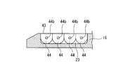
- FIG. 16 is a diagram illustrating a configuration of the present modification, and is a diagram illustrating a state in which the pulling member of the present modification is attached to the first jaw.
- FIG. 17 is a diagram illustrating a state in which the pulling member of the present modification is attached to the tissue.
- the first locked portion 44 and the second locked portion 47 of the tag 41 have holes 44b and 47b for inserting gripping forceps and the like.
- the 1st to-be-latched part 44 and the 2nd to-be-latched part 47 in this embodiment have the circular arc-shaped outline shape centering on the center of the through-hole in the hole parts 44b and 47b.
- a plurality of holes 44 b and 47 b are provided side by side in the longitudinal axis direction of the base 11 in a state where the tag 41 is attached to the first gripping surface 17.
- One or more holes 44b and 47b may be provided in the first locked portion 44 and one or more in the second locked portion 47.
- FIG. 18 is a diagram illustrating a configuration of the present modification, and is a diagram illustrating a state in which the pulling member of the present modification is attached to the first jaw.
- FIG. 19 is a diagram illustrating a state in which the pulling member of the present modification is attached to the tissue.
- the first piece 42 is separated from each other in the longitudinal axis direction of the base portion 11 in a state in which the tag 41 is attached to the first gripping surface 17.
- a plurality of second locked portions having one locked portion 44 and having a second piece 45 spaced apart from each other in the longitudinal axis direction of the base portion 11 in a state where the tag 41 is attached to the first gripping surface 17. 47.
- the plurality of first locked portions 44 and the plurality of second locked portions 47 are alternately arranged in the longitudinal axis direction of the base portion 11. Yes.
- the groove part 22 has the 1st accommodation groove
- the plurality of first accommodation grooves 22 a and the plurality of second accommodation grooves 22 b are alternately arranged.
- the blade portion 35 when the blade portion 35 can contact the first locked portion 44 in the process of moving the blade portion 35 along the groove portion 22, the blade portion 35 can contact the second wall surface 24. When the portion 35 can contact the second locked portion 47, the blade portion 35 can contact the first wall surface 23. That is, the blade portion 35 does not contact both the first locked portion 44 and the second locked portion 47 at the same time. In this modified example, it is possible to prevent the blade portion 35 from being caught by the first locked portion 44 or the second locked portion 47 and being completely cut off.
- FIG. 20 is a diagram illustrating a configuration of the present modification, and is a diagram illustrating a state in which the pulling member of the present modification is attached to the first jaw.
- the second groove portion 22A for inserting the tag 41 in addition to the groove portion 22 in which the blade portion 35 advances and retreats.
- the holder body portion 16 is formed.
- the second groove portion 22A has a first follower groove 22A1 and a second follower groove 22A2 at positions spaced apart from each other with the groove portion 22 interposed therebetween.
- the first follower groove 22 ⁇ / b> A ⁇ b> 1 is a groove extending in parallel with the groove portion 22.
- the first follower groove 22A1 has a wall surface corresponding to the first wall surface 23 described in the first embodiment, and the first locked portion 44 of the tag 41 is bonded or press-fitted.
- the second follower groove 22 ⁇ / b> A ⁇ b> 2 is a groove extending in parallel with the groove portion 22.
- the second follower groove 22A2 has a wall surface corresponding to the second wall surface 24 described in the first embodiment, and the second locked portion 47 of the tag 41 is bonded or press-fitted. Even with such a configuration, the same effects as those of the first embodiment can be obtained.
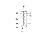
- FIG. 21 is a perspective view showing a configuration of a distal portion in the surgical instrument of the present embodiment.
- 22 is a cross-sectional view taken along line XXII-XXII in FIG.
- FIG. 23 is a view showing a state in which the pulling member is attached to the tissue and the tissue is further separated by the surgical instrument of the present embodiment.
- the surgical instrument 1 ⁇ / b> A replaces the traction member 40 described in the first embodiment with the traction described in the first embodiment.
- the member 40 has a pulling member 40A having a different configuration.
- the pulling member 40 ⁇ / b> A is an elongated member that extends across the opening of the housing portion 18 of the holder body portion 16.
- the pulling member 40 ⁇ / b> A is attached to the first gripping surface 17 along the first gripping surface 17 so as to intersect the groove portion 22.
- the pulling member 40 ⁇ / b> A is bonded to the first gripping surface 17 of the holder body portion 16.
- the adhesion force of the pulling member 40A to the first gripping surface 17 is such that the pulling member 40A is separated from the first gripping surface 17 when the first jaw 10 is separated from the tissue after the pulling member 40A is connected to the tissue by the staple 27. It is possible size.
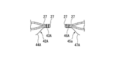
- the staple 27 penetrates the pulling member 40A, is inserted into the tissue, and is connected to the tissue in the same manner as the pulling member 40 of the first embodiment. After the traction member 40A is connected to the tissue, the traction member 40A is separated together with the tissue by the blade portion 35 that separates the tissue. Accordingly, the pulling member 40A is divided into a first piece 42A that is locked to the tissue by the first staple row 20 and a second piece 45A that is locked to the tissue by the second staple row 21.
- the first piece 42A and the second piece 45A of the pulling member 40A in the present embodiment are grasped in place of the tissue sutured by the staple 27 and the second locked portion 44A and the second piece 44A. Each has a locked portion 47A.
- the surgical instrument 1A of the present embodiment has the same effects as those of the first embodiment.
- the traction member 40A has a loop for facilitating grasping by the grasping forceps, or the traction member 40A is difficult to be removed from the grasping forceps when the traction member 40A is grasped by the grasping forceps. May have a ball part or the like.
- the pulling member 40A may have a thread shape, and a loop or a ball part may be formed by a yarn knot. Moreover, you may attach several 40 A of pulling members to the 1st holding surface 17 as needed.
- FIG. 24 is a partial cross-sectional view showing the configuration of this modification.
- the pulling member 40 ⁇ / b> A is bonded to the second gripping surface 51 of the second jaw 50.
- the bonding position of the pulling member 40A on the second gripping surface 51 is the same as in the second embodiment. This is a position where the staple 27 can penetrate.
- the pulling member 40 ⁇ / b> A is bonded to the second gripping surface 51 so as to cross the opening portion of the molding pocket 52 and intersect the escape groove 53 on the second gripping surface 51. Even if it is such a structure, there exists an effect similar to the said 1st Embodiment and the said 2nd Embodiment.
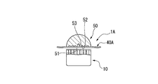
- FIG. 25 is a partial cross-sectional view showing the configuration of this modification.
- FIG. 26 is a diagram illustrating a state in which the pulling member of the present modification is attached to the tissue.
- FIG. 27 is a perspective view showing another configuration example of the pulling member of the present modification.
- the traction member 40A As shown in FIGS. 25 and 26, in this modification, instead of the traction member 40A described in the modification 2-1 above, the traction member further formed with an annular portion 48 into which the second jaw 50 is inserted. 40B.
- the ring portion 48 has a fragile portion 49 at a position facing the portion disposed on the second gripping surface 51. The fragile portion 49 is easily separated into the first piece 42B and the second piece 45B.
- the pulling member 40 ⁇ / b> B is engaged with the outer peripheral surface of the second jaw 50 by inserting the second jaw 50 into the ring portion 48.
- the pulling member 40B is engaged with the second jaw 50 at a position where the staple 27 can penetrate, as in the first and second embodiments.
- a portion of the ring portion 48 located on the second gripping surface 51 is separated together with the tissue by the blade portion 35. Further, the ring portion 48 is cut off at the fragile portion 49, whereby the pulling member 40B is locked to the tissue by the first staple row 20 and the first staple row 20 and the second staple row 21. It is divided into second pieces 45B.
- the first piece 42B and the second piece 45B of the pulling member 40B in the present embodiment are grasped in place of the tissue sutured by the staple 27 and the second locked portion 44B and the second piece 44B.
- Each has a locked portion 47B.
- the same effects as those of the first embodiment and the second embodiment are obtained. Furthermore, in this modification, when the pulling member 40B is attached to the tissue and the fragile portion 49 is further cut away, the fragile portion 49 is at a position spaced from the tissue so as to protrude from the tissue. For this reason, after the traction member 40B is attached to the tissue, the fragile portion 49 can be easily grasped when the traction member 40B is grasped by grasping forceps or the like. Then, by gripping the fragile portion 49 and moving or pulling the pulling member 40B, the tissue after separation can be moved or pulled without directly gripping the tissue or the staple 27.
- the pulling member 40 ⁇ / b> B in this modification may have a configuration in which the first jaw 10 is inserted into the ring portion 48 instead of the second jaw 50 being inserted into the ring portion 48.
- a plurality of pulling members 40B may be attached to the first jaw 10 or the second jaw 50 as necessary. Furthermore, you may use it, after moving the traction member 40B attached to the 1st jaw 10 or the 2nd jaw 50 as needed.
- the pulling member 40B in the present modification has a cylindrical portion 48A and a fragile portion 49A corresponding to the annular portion 48 which are sheet-like and BR> L as in the first embodiment. It may be a structure.
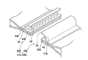
- FIG. 28 is a perspective view showing the configuration of the present modification.
- the first piece 42C connected to the tissue by the first staple row 20 and the tissue by the second staple row 21 are used.
- the second embodiment is that the first jaw 10 has a storage portion 16A and a storage portion 16B for storing the first piece 42C and the second piece 45C, respectively.
- the configuration is different from that of the surgical instrument 1 ⁇ / b> A described above.
- the first piece 42 ⁇ / b> C is disposed at the distal end portion of the first gripping surface 17 such that the first piece 42 ⁇ / b> C is connected to the tissue by the staple 27 located at the most distal end in the first staple row 20.
- the first piece 42C and the staple 27 may be fixed in advance by caulking.
- the second piece 45 ⁇ / b> C is disposed at the distal end portion of the first gripping surface 17 so as to be connected to the tissue by the staple 27 located at the most distal end in the second staple row 21.
- the second piece 45C and the staple 27 are fixed by caulking.
- the first piece 42 ⁇ / b> C and the second piece 45 ⁇ / b> C may be provided with the loops and ball portions described in the second embodiment.
- FIG. 29 is a side view showing the surgical instrument of the present embodiment.
- FIG. 30 is a plan view showing a first gripping surface of the first jaw.
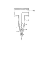
- FIG. 31 is a partial cross-sectional view showing the internal structure of the distal portion of the surgical instrument.
- FIG. 32 is a cross-sectional view showing a needle tube of a surgical instrument.
- the surgical instrument 1B of the present embodiment shown in FIG. 29 is different in configuration from the surgical instrument 1 of the first embodiment and the surgical instrument 1A of the second embodiment in that tissues are sutured together with an adhesive.
- the surgical instrument 1 ⁇ / b> B according to the present embodiment does not have the staple 27 and faces the first jaw 10 toward the second gripping surface 51.
- a plurality of protruding needle tubes 80 are provided. The plurality of needle tubes 80 are fixed to each accommodating portion 18.
- the surgical instrument 1B of the present embodiment is an operation for performing an operation for opening and closing the first jaw 10 and the second jaw 50 and an operation for supplying an adhesive to the tissue to be sutured.
- the unit 63B is provided in place of the operation unit 63 described in the first embodiment.
- the surgical instrument 1B of this embodiment has the separation part for separating tissue similarly to the said 1st Embodiment.
- the first jaw 10 has the groove portion 22 described in the first embodiment, and has a plurality of needle tubes 80 on the first gripping surface 17. As shown in FIG. 31, a hollow portion 10 a communicating with the needle tube 80 is provided inside the first jaw 10.
- the plurality of needle tubes 80 shown in FIGS. 31 and 32 have one or more openings for releasing the adhesive. Further, the plurality of needle tubes 80 are communicated with the hollow portion 10 a inside the first jaw 10. The hollow portion 10a of the first jaw 10 is used as a flow path through which the adhesive flows. The hollow portion 10a inside the first jaw 10 communicates with the distal end of the tube 81 extending from the proximal end of the first jaw 10 to the operation portion 63B.
- the tag 41 described in the first embodiment is attached to the first gripping surface 17 of the first jaw 10.
- the tag 41 in the present embodiment is attached to the first gripping surface 17 following the first gripping surface 17 with the needle tube 80 already penetrated.
- the operation unit 63B of the surgical instrument 1B slides with respect to the rod-shaped main body 66B and the main body 66B in order to open and close the first jaw 10 and the second jaw 50.
- a slider 78 that can be attached and a pump unit 82 that feeds the adhesive into the tube 81 are provided.
- the main body 66B and the slider 78 have a ratchet mechanism 74 that regulates the movement of the slider 78 so that the movement direction of the slider 78 relative to the main body 66B is one direction.
- the ratchet mechanism 74 includes a tooth portion 75 provided side by side in the axial direction of the main body 66B, an engagement protrusion 76 provided on the slider 78, and a release switch for releasing the engagement between the tooth portion 75 and the engagement protrusion 76. 77.
- the ratchet mechanism 74 can move the slider 78 with respect to the main body 66B without operating the release switch 77.
- operation of the release switch 77 is required.
- the first jaw 10 and the second jaw 50 are closed using the slider 78, the first jaw 10 and the second jaw 50 are closed by the ratchet mechanism 74. It is held in the state.
- the pump unit 82 is, for example, a syringe pump connected to the proximal end of the tube 81.
- the tissue is sutured by an adhesive released from the needle tube 80 inserted into the tissue. Further, the adhesive released from the needle tube 80 bonds the tag 41 and the tissue.
- the tag 41 is connected to the tissue. Therefore, also in the present embodiment, the tissue is moved or pulled by grasping the first locked portion 44 or the second locked portion 47 without grasping the suture region SA in the sutured tissue. Can do.
- the surgical instrument 1B of the present embodiment has the same effects as the surgical instrument 1 described in the first embodiment.
- the plurality of needle tubes 80 may be configured to protrude from the accommodating portion 18 by the cam portion 33 described in the first embodiment. In this case, when the plurality of needle tubes 80 are completely accommodated in the accommodating portion 18, the tissue can be grasped similarly to the grasping forceps using the first jaw 10 and the second jaw 50.
- tissue destruction and suture failure due to the procedure following suturing and separation are unlikely to occur.
Abstract
Priority Applications (4)
| Application Number | Priority Date | Filing Date | Title |
|---|---|---|---|
| CN201580016707.4A CN106132318B (zh) | 2014-03-28 | 2015-03-06 | 手术用器具 |
| JP2015553331A JP5985078B2 (ja) | 2014-03-28 | 2015-03-06 | 手術用器具 |
| EP15769032.2A EP3123948B1 (fr) | 2014-03-28 | 2015-03-06 | Instrument chirurgical |
| US15/267,831 US20170000483A1 (en) | 2014-03-28 | 2016-09-16 | Surgical instrument |
Applications Claiming Priority (2)
| Application Number | Priority Date | Filing Date | Title |
|---|---|---|---|
| JP2014-070397 | 2014-03-28 | ||
| JP2014070397 | 2014-03-28 |
Related Child Applications (1)
| Application Number | Title | Priority Date | Filing Date |
|---|---|---|---|
| US15/267,831 Continuation US20170000483A1 (en) | 2014-03-28 | 2016-09-16 | Surgical instrument |
Publications (1)
| Publication Number | Publication Date |
|---|---|
| WO2015146548A1 true WO2015146548A1 (fr) | 2015-10-01 |
Family
ID=54195074
Family Applications (1)
| Application Number | Title | Priority Date | Filing Date |
|---|---|---|---|
| PCT/JP2015/056689 WO2015146548A1 (fr) | 2014-03-28 | 2015-03-06 | Instrument chirurgical |
Country Status (5)
| Country | Link |
|---|---|
| US (1) | US20170000483A1 (fr) |
| EP (1) | EP3123948B1 (fr) |
| JP (1) | JP5985078B2 (fr) |
| CN (1) | CN106132318B (fr) |
| WO (1) | WO2015146548A1 (fr) |
Cited By (4)
| Publication number | Priority date | Publication date | Assignee | Title |
|---|---|---|---|---|
| EP3146908A1 (fr) * | 2015-09-24 | 2017-03-29 | Ethicon Endo-Surgery, LLC | Appareil et procédé pour faire glisser une ligne d'agrafes droite |
| WO2017192438A1 (fr) * | 2016-05-06 | 2017-11-09 | Ethicon, Inc. | Agrafeuse/découpeuse chirurgicale et contrefort étendu |
| US10258337B2 (en) | 2016-04-20 | 2019-04-16 | Ethicon Llc | Surgical staple cartridge with severed tissue edge adjunct |
| JP2019146963A (ja) * | 2018-02-27 | 2019-09-05 | コヴィディエン リミテッド パートナーシップ | 変化するステープル高さ、およびステープルサイズを有する電動ステープラー |
Families Citing this family (101)
| Publication number | Priority date | Publication date | Assignee | Title |
|---|---|---|---|---|
| US10966717B2 (en) | 2016-01-07 | 2021-04-06 | Covidien Lp | Surgical fastener apparatus |
| US10660623B2 (en) | 2016-01-15 | 2020-05-26 | Covidien Lp | Centering mechanism for articulation joint |
| US10561419B2 (en) | 2016-05-04 | 2020-02-18 | Covidien Lp | Powered end effector assembly with pivotable channel |
| US10492784B2 (en) | 2016-11-08 | 2019-12-03 | Covidien Lp | Surgical tool assembly with compact firing assembly |
| US10463371B2 (en) | 2016-11-29 | 2019-11-05 | Covidien Lp | Reload assembly with spent reload indicator |
| US10709901B2 (en) | 2017-01-05 | 2020-07-14 | Covidien Lp | Implantable fasteners, applicators, and methods for brachytherapy |
| US10952767B2 (en) | 2017-02-06 | 2021-03-23 | Covidien Lp | Connector clip for securing an introducer to a surgical fastener applying apparatus |
| US20180235618A1 (en) | 2017-02-22 | 2018-08-23 | Covidien Lp | Loading unit for surgical instruments with low profile pushers |
| US10849621B2 (en) | 2017-02-23 | 2020-12-01 | Covidien Lp | Surgical stapler with small diameter endoscopic portion |
| US11350915B2 (en) | 2017-02-23 | 2022-06-07 | Covidien Lp | Surgical stapler with small diameter endoscopic portion |
| US10299790B2 (en) | 2017-03-03 | 2019-05-28 | Covidien Lp | Adapter with centering mechanism for articulation joint |
| US10660641B2 (en) | 2017-03-16 | 2020-05-26 | Covidien Lp | Adapter with centering mechanism for articulation joint |
| US10603035B2 (en) | 2017-05-02 | 2020-03-31 | Covidien Lp | Surgical loading unit including an articulating end effector |
| US11324502B2 (en) | 2017-05-02 | 2022-05-10 | Covidien Lp | Surgical loading unit including an articulating end effector |
| US10524784B2 (en) | 2017-05-05 | 2020-01-07 | Covidien Lp | Surgical staples with expandable backspan |
| US10390826B2 (en) | 2017-05-08 | 2019-08-27 | Covidien Lp | Surgical stapling device with elongated tool assembly and methods of use |
| US10420551B2 (en) | 2017-05-30 | 2019-09-24 | Covidien Lp | Authentication and information system for reusable surgical instruments |
| US10478185B2 (en) | 2017-06-02 | 2019-11-19 | Covidien Lp | Tool assembly with minimal dead space |
| US10624636B2 (en) | 2017-08-23 | 2020-04-21 | Covidien Lp | Surgical stapling device with floating staple cartridge |
| US10806452B2 (en) | 2017-08-24 | 2020-10-20 | Covidien Lp | Loading unit for a surgical stapling instrument |
| US10925603B2 (en) | 2017-11-14 | 2021-02-23 | Covidien Lp | Reload with articulation stabilization system |
| US10863987B2 (en) | 2017-11-16 | 2020-12-15 | Covidien Lp | Surgical instrument with imaging device |
| US10945732B2 (en) | 2018-01-17 | 2021-03-16 | Covidien Lp | Surgical stapler with self-returning assembly |
| US11369371B2 (en) | 2018-03-02 | 2022-06-28 | Covidien Lp | Surgical stapling instrument |
| US10849622B2 (en) | 2018-06-21 | 2020-12-01 | Covidien Lp | Articulated stapling with fire lock |
| US10736631B2 (en) | 2018-08-07 | 2020-08-11 | Covidien Lp | End effector with staple cartridge ejector |
| US10849620B2 (en) | 2018-09-14 | 2020-12-01 | Covidien Lp | Connector mechanisms for surgical stapling instruments |
| US11510669B2 (en) | 2020-09-29 | 2022-11-29 | Covidien Lp | Hand-held surgical instruments |
| US11090051B2 (en) | 2018-10-23 | 2021-08-17 | Covidien Lp | Surgical stapling device with floating staple cartridge |
| US10912563B2 (en) | 2019-01-02 | 2021-02-09 | Covidien Lp | Stapling device including tool assembly stabilizing member |
| US11344297B2 (en) | 2019-02-28 | 2022-05-31 | Covidien Lp | Surgical stapling device with independently movable jaws |
| US11259808B2 (en) | 2019-03-13 | 2022-03-01 | Covidien Lp | Tool assemblies with a gap locking member |
| US11284892B2 (en) | 2019-04-01 | 2022-03-29 | Covidien Lp | Loading unit and adapter with modified coupling assembly |
| US11284893B2 (en) | 2019-04-02 | 2022-03-29 | Covidien Lp | Stapling device with articulating tool assembly |
| US11241228B2 (en) | 2019-04-05 | 2022-02-08 | Covidien Lp | Surgical instrument including an adapter assembly and an articulating surgical loading unit |
| US11224424B2 (en) | 2019-08-02 | 2022-01-18 | Covidien Lp | Linear stapling device with vertically movable knife |
| AU2020328574A1 (en) * | 2019-08-14 | 2022-03-03 | Lsi Solutions, Inc. | Device for vessel harvesting |
| US11406385B2 (en) | 2019-10-11 | 2022-08-09 | Covidien Lp | Stapling device with a gap locking member |
| US11123068B2 (en) | 2019-11-08 | 2021-09-21 | Covidien Lp | Surgical staple cartridge |
| US11707274B2 (en) | 2019-12-06 | 2023-07-25 | Covidien Lp | Articulating mechanism for surgical instrument |
| US11109862B2 (en) | 2019-12-12 | 2021-09-07 | Covidien Lp | Surgical stapling device with flexible shaft |
| US11737747B2 (en) | 2019-12-17 | 2023-08-29 | Covidien Lp | Hand-held surgical instruments |
| US11452524B2 (en) | 2020-01-31 | 2022-09-27 | Covidien Lp | Surgical stapling device with lockout |
| US11278282B2 (en) | 2020-01-31 | 2022-03-22 | Covidien Lp | Stapling device with selective cutting |
| CN115135251A (zh) | 2020-02-14 | 2022-09-30 | 柯惠有限合伙公司 | 用于手术缝合钉且在外周壁上有用于夹持组织的脊的仓支架 |
| US11344301B2 (en) | 2020-03-02 | 2022-05-31 | Covidien Lp | Surgical stapling device with replaceable reload assembly |
| US11344302B2 (en) | 2020-03-05 | 2022-05-31 | Covidien Lp | Articulation mechanism for surgical stapling device |
| US11246593B2 (en) | 2020-03-06 | 2022-02-15 | Covidien Lp | Staple cartridge |
| US11707278B2 (en) | 2020-03-06 | 2023-07-25 | Covidien Lp | Surgical stapler tool assembly to minimize bleeding |
| US11357505B2 (en) | 2020-03-10 | 2022-06-14 | Covidien Lp | Surgical stapling apparatus with firing lockout mechanism |
| US11317911B2 (en) | 2020-03-10 | 2022-05-03 | Covidien Lp | Tool assembly with replaceable cartridge assembly |
| US11406383B2 (en) | 2020-03-17 | 2022-08-09 | Covidien Lp | Fire assisted powered EGIA handle |
| US11331098B2 (en) | 2020-04-01 | 2022-05-17 | Covidien Lp | Sled detection device |
| US11426159B2 (en) | 2020-04-01 | 2022-08-30 | Covidien Lp | Sled detection device |
| US11504117B2 (en) | 2020-04-02 | 2022-11-22 | Covidien Lp | Hand-held surgical instruments |
| US11937794B2 (en) | 2020-05-11 | 2024-03-26 | Covidien Lp | Powered handle assembly for surgical devices |
| US11191537B1 (en) | 2020-05-12 | 2021-12-07 | Covidien Lp | Stapling device with continuously parallel jaws |
| US11406387B2 (en) | 2020-05-12 | 2022-08-09 | Covidien Lp | Surgical stapling device with replaceable staple cartridge |
| US11534167B2 (en) | 2020-05-28 | 2022-12-27 | Covidien Lp | Electrotaxis-conducive stapling |
| US11191538B1 (en) | 2020-06-08 | 2021-12-07 | Covidien Lp | Surgical stapling device with parallel jaw closure |
| US11844517B2 (en) | 2020-06-25 | 2023-12-19 | Covidien Lp | Linear stapling device with continuously parallel jaws |
| US11324500B2 (en) | 2020-06-30 | 2022-05-10 | Covidien Lp | Surgical stapling device |
| US11517305B2 (en) | 2020-07-09 | 2022-12-06 | Covidien Lp | Contoured staple pusher |
| US11446028B2 (en) | 2020-07-09 | 2022-09-20 | Covidien Lp | Tool assembly with pivotable clamping beam |
| US11266402B2 (en) | 2020-07-30 | 2022-03-08 | Covidien Lp | Sensing curved tip for surgical stapling instruments |
| US11439392B2 (en) | 2020-08-03 | 2022-09-13 | Covidien Lp | Surgical stapling device and fastener for pathological exam |
| US11395654B2 (en) | 2020-08-07 | 2022-07-26 | Covidien Lp | Surgical stapling device with articulation braking assembly |
| US11602342B2 (en) | 2020-08-27 | 2023-03-14 | Covidien Lp | Surgical stapling device with laser probe |
| US11678878B2 (en) | 2020-09-16 | 2023-06-20 | Covidien Lp | Articulation mechanism for surgical stapling device |
| US11660092B2 (en) | 2020-09-29 | 2023-05-30 | Covidien Lp | Adapter for securing loading units to handle assemblies of surgical stapling instruments |
| US11406384B2 (en) | 2020-10-05 | 2022-08-09 | Covidien Lp | Stapling device with drive assembly stop member |
| US11576674B2 (en) | 2020-10-06 | 2023-02-14 | Covidien Lp | Surgical stapling device with articulation lock assembly |
| US11890007B2 (en) | 2020-11-18 | 2024-02-06 | Covidien Lp | Stapling device with flex cable and tensioning mechanism |
| US11737774B2 (en) | 2020-12-04 | 2023-08-29 | Covidien Lp | Surgical instrument with articulation assembly |
| US11819200B2 (en) | 2020-12-15 | 2023-11-21 | Covidien Lp | Surgical instrument with articulation assembly |
| US11553914B2 (en) | 2020-12-22 | 2023-01-17 | Covidien Lp | Surgical stapling device with parallel jaw closure |
| US11759206B2 (en) | 2021-01-05 | 2023-09-19 | Covidien Lp | Surgical stapling device with firing lockout mechanism |
| US11744582B2 (en) | 2021-01-05 | 2023-09-05 | Covidien Lp | Surgical stapling device with firing lockout mechanism |
| US11517313B2 (en) | 2021-01-27 | 2022-12-06 | Covidien Lp | Surgical stapling device with laminated drive member |
| US11759207B2 (en) | 2021-01-27 | 2023-09-19 | Covidien Lp | Surgical stapling apparatus with adjustable height clamping member |
| US11717300B2 (en) | 2021-03-11 | 2023-08-08 | Covidien Lp | Surgical stapling apparatus with integrated visualization |
| US11497495B2 (en) | 2021-03-31 | 2022-11-15 | Covidien Lp | Continuous stapler strip for use with a surgical stapling device |
| US11666330B2 (en) | 2021-04-05 | 2023-06-06 | Covidien Lp | Surgical stapling device with lockout mechanism |
| US11576670B2 (en) | 2021-05-06 | 2023-02-14 | Covidien Lp | Surgical stapling device with optimized drive assembly |
| US11812956B2 (en) | 2021-05-18 | 2023-11-14 | Covidien Lp | Dual firing radial stapling device |
| US11696755B2 (en) | 2021-05-19 | 2023-07-11 | Covidien Lp | Surgical stapling device with reload assembly removal lockout |
| US11771423B2 (en) | 2021-05-25 | 2023-10-03 | Covidien Lp | Powered stapling device with manual retraction |
| US11510673B1 (en) | 2021-05-25 | 2022-11-29 | Covidien Lp | Powered stapling device with manual retraction |
| US11701119B2 (en) | 2021-05-26 | 2023-07-18 | Covidien Lp | Powered stapling device with rack release |
| US11576675B2 (en) | 2021-06-07 | 2023-02-14 | Covidien Lp | Staple cartridge with knife |
| US11707275B2 (en) | 2021-06-29 | 2023-07-25 | Covidien Lp | Asymmetrical surgical stapling device |
| US11617579B2 (en) | 2021-06-29 | 2023-04-04 | Covidien Lp | Ultra low profile surgical stapling instrument for tissue resections |
| US11602344B2 (en) | 2021-06-30 | 2023-03-14 | Covidien Lp | Surgical stapling apparatus with firing lockout assembly |
| US11540831B1 (en) | 2021-08-12 | 2023-01-03 | Covidien Lp | Staple cartridge with actuation sled detection |
| US11779334B2 (en) | 2021-08-19 | 2023-10-10 | Covidien Lp | Surgical stapling device including a manual retraction assembly |
| US11576671B1 (en) | 2021-08-20 | 2023-02-14 | Covidien Lp | Small diameter linear surgical stapling apparatus |
| US11707277B2 (en) | 2021-08-20 | 2023-07-25 | Covidien Lp | Articulating surgical stapling apparatus with pivotable knife bar guide assembly |
| US11864761B2 (en) | 2021-09-14 | 2024-01-09 | Covidien Lp | Surgical instrument with illumination mechanism |
| US11653922B2 (en) | 2021-09-29 | 2023-05-23 | Covidien Lp | Surgical stapling device with firing lockout mechanism |
| US11660094B2 (en) | 2021-09-29 | 2023-05-30 | Covidien Lp | Surgical fastening instrument with two-part surgical fasteners |
| US11849949B2 (en) | 2021-09-30 | 2023-12-26 | Covidien Lp | Surgical stapling device with firing lockout member |
Citations (7)
| Publication number | Priority date | Publication date | Assignee | Title |
|---|---|---|---|---|
| US6273897B1 (en) * | 2000-02-29 | 2001-08-14 | Ethicon, Inc. | Surgical bettress and surgical stapling apparatus |
| JP2009189849A (ja) * | 2008-02-15 | 2009-08-27 | Ethicon Endo Surgery Inc | 外科手術用エンドエフェクタと共に使用する、整合特徴部および保持特徴部を有する支持体 |
| JP2012065699A (ja) * | 2010-09-21 | 2012-04-05 | Doshisha | 親水性高分子を含む自動縫合器用縫合補強材 |
| US20120234900A1 (en) * | 2011-03-15 | 2012-09-20 | Ethicon Endo-Surgery, Inc. | Surgical staple cartridges with tissue tethers for manipulating divided tissue and methods of using same |
| US20130172928A1 (en) * | 2010-11-10 | 2013-07-04 | Covidien Lp | Staple Formed Over the Wire Wound Closure Procedure |
| US20140061280A1 (en) * | 2009-10-15 | 2014-03-06 | Covidien Lp | Staple line reinforcement for anvil and cartridge |
| EP2742872A1 (fr) * | 2012-12-13 | 2014-06-18 | Covidien LP | Renfort plié destiné à être utilisé avec un appareil chirurgical |
Family Cites Families (4)
| Publication number | Priority date | Publication date | Assignee | Title |
|---|---|---|---|---|
| US5976149A (en) * | 1997-02-11 | 1999-11-02 | Medidea, Llc | Method and apparatus for aligning a prosthetic element |
| US6325810B1 (en) * | 1999-06-30 | 2001-12-04 | Ethicon, Inc. | Foam buttress for stapling apparatus |
| WO2009143331A1 (fr) * | 2008-05-21 | 2009-11-26 | Cook Biotech Incorporated | Dispositifs et procédés pour l'application de bandeaux de renfort sur des appareils de fixation chirurgicaux |
| US8317071B1 (en) * | 2009-03-09 | 2012-11-27 | Cardica, Inc. | Endocutter with auto-feed buttress |
-
2015
- 2015-03-06 JP JP2015553331A patent/JP5985078B2/ja active Active
- 2015-03-06 EP EP15769032.2A patent/EP3123948B1/fr active Active
- 2015-03-06 WO PCT/JP2015/056689 patent/WO2015146548A1/fr active Application Filing
- 2015-03-06 CN CN201580016707.4A patent/CN106132318B/zh not_active Expired - Fee Related
-
2016
- 2016-09-16 US US15/267,831 patent/US20170000483A1/en not_active Abandoned
Patent Citations (7)
| Publication number | Priority date | Publication date | Assignee | Title |
|---|---|---|---|---|
| US6273897B1 (en) * | 2000-02-29 | 2001-08-14 | Ethicon, Inc. | Surgical bettress and surgical stapling apparatus |
| JP2009189849A (ja) * | 2008-02-15 | 2009-08-27 | Ethicon Endo Surgery Inc | 外科手術用エンドエフェクタと共に使用する、整合特徴部および保持特徴部を有する支持体 |
| US20140061280A1 (en) * | 2009-10-15 | 2014-03-06 | Covidien Lp | Staple line reinforcement for anvil and cartridge |
| JP2012065699A (ja) * | 2010-09-21 | 2012-04-05 | Doshisha | 親水性高分子を含む自動縫合器用縫合補強材 |
| US20130172928A1 (en) * | 2010-11-10 | 2013-07-04 | Covidien Lp | Staple Formed Over the Wire Wound Closure Procedure |
| US20120234900A1 (en) * | 2011-03-15 | 2012-09-20 | Ethicon Endo-Surgery, Inc. | Surgical staple cartridges with tissue tethers for manipulating divided tissue and methods of using same |
| EP2742872A1 (fr) * | 2012-12-13 | 2014-06-18 | Covidien LP | Renfort plié destiné à être utilisé avec un appareil chirurgical |
Cited By (7)
| Publication number | Priority date | Publication date | Assignee | Title |
|---|---|---|---|---|
| EP3146908A1 (fr) * | 2015-09-24 | 2017-03-29 | Ethicon Endo-Surgery, LLC | Appareil et procédé pour faire glisser une ligne d'agrafes droite |
| WO2017053191A1 (fr) * | 2015-09-24 | 2017-03-30 | Ethicon Endo-Surgery, Llc | Appareil et procédé pour serrer une ligne d'agrafes droite |
| US10492790B2 (en) | 2015-09-24 | 2019-12-03 | Ethicon Llc | Apparatus and method for cinching a straight staple line |
| US11510676B2 (en) | 2015-09-24 | 2022-11-29 | Cilag Gmbh International | Apparatus and method for cinching a straight staple line |
| US10258337B2 (en) | 2016-04-20 | 2019-04-16 | Ethicon Llc | Surgical staple cartridge with severed tissue edge adjunct |
| WO2017192438A1 (fr) * | 2016-05-06 | 2017-11-09 | Ethicon, Inc. | Agrafeuse/découpeuse chirurgicale et contrefort étendu |
| JP2019146963A (ja) * | 2018-02-27 | 2019-09-05 | コヴィディエン リミテッド パートナーシップ | 変化するステープル高さ、およびステープルサイズを有する電動ステープラー |
Also Published As
| Publication number | Publication date |
|---|---|
| JPWO2015146548A1 (ja) | 2017-04-13 |
| EP3123948B1 (fr) | 2020-01-15 |
| EP3123948A1 (fr) | 2017-02-01 |
| EP3123948A4 (fr) | 2017-11-29 |
| CN106132318B (zh) | 2018-11-06 |
| CN106132318A (zh) | 2016-11-16 |
| JP5985078B2 (ja) | 2016-09-06 |
| US20170000483A1 (en) | 2017-01-05 |
Similar Documents
| Publication | Publication Date | Title |
|---|---|---|
| WO2015146548A1 (fr) | Instrument chirurgical | |
| JP6346358B2 (ja) | 内視鏡巾着縫合糸外科用デバイス | |
| RU2677048C2 (ru) | Накладыватель изогнутой иглы | |
| US9186134B2 (en) | Suture and retainer assembly and SULU | |
| JP6384682B2 (ja) | 腹腔鏡ポートサイト閉鎖装置 | |
| US9247938B2 (en) | Suture fastening device | |
| EP2311384B1 (fr) | Applicateur d'agrafes chirurgicales | |
| US5601575A (en) | Needle driving device | |
| US7988027B2 (en) | Crimp and release of suture holding buttress material | |
| JP2021512755A (ja) | リニア外科用ステープラの近位部分用の解放可能な連結機構 | |
| WO2006082810A1 (fr) | Dispositif de ligature pour suture medicale et outil de ligature pour suture medicale | |
| JP2003102735A5 (fr) | ||
| JP2015530192A (ja) | ハーフループクリップを有する吻合クリップツール | |
| WO2016021290A1 (fr) | Instrument chirurgical | |
| US20160038140A1 (en) | Suture device | |
| US20060259046A1 (en) | Body tissue incision closing instrument | |
| JP2008237645A (ja) | 内視鏡用処置具及び留置具 | |
| NL2019974B1 (en) | Suture device | |
| US11779342B2 (en) | Laparoscopic purse string suture device | |
| US10881400B2 (en) | Medical stapler system | |
| JP2013530787A (ja) | 中空器官に吻合を行うステープル留め装置 | |
| JP6010244B1 (ja) | 自動縫合器誘導用チューブ | |
| JP2013517836A (ja) | 中空器官に吻合を行うステープル留め装置 |
Legal Events
| Date | Code | Title | Description |
|---|---|---|---|
| ENP | Entry into the national phase |
Ref document number: 2015553331 Country of ref document: JP Kind code of ref document: A |
|
| 121 | Ep: the epo has been informed by wipo that ep was designated in this application |
Ref document number: 15769032 Country of ref document: EP Kind code of ref document: A1 |
|
| NENP | Non-entry into the national phase |
Ref country code: DE |
|
| REEP | Request for entry into the european phase |
Ref document number: 2015769032 Country of ref document: EP |
|
| WWE | Wipo information: entry into national phase |
Ref document number: 2015769032 Country of ref document: EP |