WO2015146375A1 - ジェットエンジン、飛しょう体及びジェットエンジンの動作方法 - Google Patents
ジェットエンジン、飛しょう体及びジェットエンジンの動作方法 Download PDFInfo
- Publication number
- WO2015146375A1 WO2015146375A1 PCT/JP2015/054301 JP2015054301W WO2015146375A1 WO 2015146375 A1 WO2015146375 A1 WO 2015146375A1 JP 2015054301 W JP2015054301 W JP 2015054301W WO 2015146375 A1 WO2015146375 A1 WO 2015146375A1
- Authority
- WO
- WIPO (PCT)
- Prior art keywords
- jet engine
- flame
- flame holder
- combustor
- fuel
- Prior art date
- Legal status (The legal status is an assumption and is not a legal conclusion. Google has not performed a legal analysis and makes no representation as to the accuracy of the status listed.)
- Ceased
Links
Images


Classifications
-
- F—MECHANICAL ENGINEERING; LIGHTING; HEATING; WEAPONS; BLASTING
- F23—COMBUSTION APPARATUS; COMBUSTION PROCESSES
- F23R—GENERATING COMBUSTION PRODUCTS OF HIGH PRESSURE OR HIGH VELOCITY, e.g. GAS-TURBINE COMBUSTION CHAMBERS
- F23R3/00—Continuous combustion chambers using liquid or gaseous fuel
- F23R3/02—Continuous combustion chambers using liquid or gaseous fuel characterised by the air-flow or gas-flow configuration
- F23R3/16—Continuous combustion chambers using liquid or gaseous fuel characterised by the air-flow or gas-flow configuration with devices inside the flame tube or the combustion chamber to influence the air or gas flow
- F23R3/18—Flame stabilising means, e.g. flame holders for after-burners of jet-propulsion plants
- F23R3/22—Flame stabilising means, e.g. flame holders for after-burners of jet-propulsion plants movable, e.g. to an inoperative position; adjustable, e.g. self-adjusting
-
- F—MECHANICAL ENGINEERING; LIGHTING; HEATING; WEAPONS; BLASTING
- F02—COMBUSTION ENGINES; HOT-GAS OR COMBUSTION-PRODUCT ENGINE PLANTS
- F02C—GAS-TURBINE PLANTS; AIR INTAKES FOR JET-PROPULSION PLANTS; CONTROLLING FUEL SUPPLY IN AIR-BREATHING JET-PROPULSION PLANTS
- F02C7/00—Features, components parts, details or accessories, not provided for in, or of interest apart form groups F02C1/00 - F02C6/00; Air intakes for jet-propulsion plants
- F02C7/04—Air intakes for gas-turbine plants or jet-propulsion plants
- F02C7/042—Air intakes for gas-turbine plants or jet-propulsion plants having variable geometry
-
- F—MECHANICAL ENGINEERING; LIGHTING; HEATING; WEAPONS; BLASTING
- F02—COMBUSTION ENGINES; HOT-GAS OR COMBUSTION-PRODUCT ENGINE PLANTS
- F02K—JET-PROPULSION PLANTS
- F02K7/00—Plants in which the working fluid is used in a jet only, i.e. the plants not having a turbine or other engine driving a compressor or a ducted fan; Control thereof
- F02K7/10—Plants in which the working fluid is used in a jet only, i.e. the plants not having a turbine or other engine driving a compressor or a ducted fan; Control thereof characterised by having ram-action compression, i.e. aero-thermo-dynamic-ducts or ram-jet engines
- F02K7/18—Composite ram-jet/rocket engines
-
- F—MECHANICAL ENGINEERING; LIGHTING; HEATING; WEAPONS; BLASTING
- F23—COMBUSTION APPARATUS; COMBUSTION PROCESSES
- F23R—GENERATING COMBUSTION PRODUCTS OF HIGH PRESSURE OR HIGH VELOCITY, e.g. GAS-TURBINE COMBUSTION CHAMBERS
- F23R3/00—Continuous combustion chambers using liquid or gaseous fuel
- F23R3/42—Continuous combustion chambers using liquid or gaseous fuel characterised by the arrangement or form of the flame tubes or combustion chambers
- F23R3/60—Support structures; Attaching or mounting means
-
- F—MECHANICAL ENGINEERING; LIGHTING; HEATING; WEAPONS; BLASTING
- F05—INDEXING SCHEMES RELATING TO ENGINES OR PUMPS IN VARIOUS SUBCLASSES OF CLASSES F01-F04
- F05D—INDEXING SCHEME FOR ASPECTS RELATING TO NON-POSITIVE-DISPLACEMENT MACHINES OR ENGINES, GAS-TURBINES OR JET-PROPULSION PLANTS
- F05D2220/00—Application
- F05D2220/10—Application in ram-jet engines or ram-jet driven vehicles
-
- F—MECHANICAL ENGINEERING; LIGHTING; HEATING; WEAPONS; BLASTING
- F05—INDEXING SCHEMES RELATING TO ENGINES OR PUMPS IN VARIOUS SUBCLASSES OF CLASSES F01-F04
- F05D—INDEXING SCHEME FOR ASPECTS RELATING TO NON-POSITIVE-DISPLACEMENT MACHINES OR ENGINES, GAS-TURBINES OR JET-PROPULSION PLANTS
- F05D2220/00—Application
- F05D2220/80—Application in supersonic vehicles excluding hypersonic vehicles or ram, scram or rocket propulsion
-
- F—MECHANICAL ENGINEERING; LIGHTING; HEATING; WEAPONS; BLASTING
- F05—INDEXING SCHEMES RELATING TO ENGINES OR PUMPS IN VARIOUS SUBCLASSES OF CLASSES F01-F04
- F05D—INDEXING SCHEME FOR ASPECTS RELATING TO NON-POSITIVE-DISPLACEMENT MACHINES OR ENGINES, GAS-TURBINES OR JET-PROPULSION PLANTS
- F05D2260/00—Function
- F05D2260/99—Ignition, e.g. ignition by warming up of fuel or oxidizer in a resonant acoustic cavity
-
- F—MECHANICAL ENGINEERING; LIGHTING; HEATING; WEAPONS; BLASTING
- F23—COMBUSTION APPARATUS; COMBUSTION PROCESSES
- F23R—GENERATING COMBUSTION PRODUCTS OF HIGH PRESSURE OR HIGH VELOCITY, e.g. GAS-TURBINE COMBUSTION CHAMBERS
- F23R2900/00—Special features of, or arrangements for continuous combustion chambers; Combustion processes therefor
- F23R2900/00015—Trapped vortex combustion chambers
-
- F—MECHANICAL ENGINEERING; LIGHTING; HEATING; WEAPONS; BLASTING
- F23—COMBUSTION APPARATUS; COMBUSTION PROCESSES
- F23R—GENERATING COMBUSTION PRODUCTS OF HIGH PRESSURE OR HIGH VELOCITY, e.g. GAS-TURBINE COMBUSTION CHAMBERS
- F23R2900/00—Special features of, or arrangements for continuous combustion chambers; Combustion processes therefor
- F23R2900/00017—Assembling combustion chamber liners or subparts
-
- Y—GENERAL TAGGING OF NEW TECHNOLOGICAL DEVELOPMENTS; GENERAL TAGGING OF CROSS-SECTIONAL TECHNOLOGIES SPANNING OVER SEVERAL SECTIONS OF THE IPC; TECHNICAL SUBJECTS COVERED BY FORMER USPC CROSS-REFERENCE ART COLLECTIONS [XRACs] AND DIGESTS
- Y02—TECHNOLOGIES OR APPLICATIONS FOR MITIGATION OR ADAPTATION AGAINST CLIMATE CHANGE
- Y02T—CLIMATE CHANGE MITIGATION TECHNOLOGIES RELATED TO TRANSPORTATION
- Y02T50/00—Aeronautics or air transport
- Y02T50/60—Efficient propulsion technologies, e.g. for aircraft
Definitions
- the present invention relates to a jet engine, a flying object, and a method for operating the jet engine, and more particularly, to a jet engine using a flame holder, a flying object, and a method for operating the jet engine.
- Turbojet engines including turbofan engines, ramjet engines, and scramjet engines are known as jet engines that fly faster than the speed of sound. These are jet engines that operate by taking in air. In particular, in the ramjet engine and the scramjet engine, the speed of the taken-in air strongly depends on the flying speed.
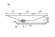
- FIG. 1A and 1B are schematic cross-sectional views schematically showing the configuration of a jet engine.
- FIG. 1A shows a case where the flying speed is slow
- FIG. 1B shows a case where the flying speed is fast.
- the jet engine 102 includes an airframe 110 and a cowl 140 that is provided below the airframe 110 so as to form a space 150 through which gas can flow.
- the lower part in front of the airframe 110 and the front part of the cowl 140 constitute an inlet 111 for introducing air into the space 150.
- the lower part in the middle of the fuselage 110 and the middle part of the cowl 140 constitute a combustor 112 that mixes and burns fuel and air.
- the lower part behind the airframe 110 and the rear part of the cowl 140 constitute a nozzle 113 that expands and discharges combustion gas.
- the combustor 112 includes a fuel injector 120 and a flame holder 121.
- the combustion ejector 120 is provided in a portion corresponding to the combustor 112 in the lower portion of the fuselage 110.
- the fuel injector 120 ejects the fuel G toward the space 150.
- the flame holder 121 is provided behind the fuel injector 120 in a portion corresponding to the combustor 112 in the lower portion of the fuselage 110.
- the flame holder 121 uses the fuel G from the fuel injector 120 to maintain the combustion flame F.
- the jet engine 102 mixes and burns the air taken in from the inlet 111 and the fuel G injected from the fuel injector 120 by the combustor 112, expands the combustion gas by the nozzle 113, and moves it backward from the airframe 110. Send it out.
- the flame F of the flame holder 121 is used for maintaining the combustion.
- a high pressure region HP is formed in front of the flame holder 121 in the combustor 112.
- the width of the high pressure region HP is determined mainly by the balance between the combustion pressure of combustion in the combustor 112 and the dynamic pressure of air taken in the inlet 111.
- the flying speed is fast (mainly in the cruise stage of the flying object) and the dynamic pressure of the air is high (FIG. 1B)
- the high pressure region HP is narrowed.
- the flying speed is low (generally in the acceleration stage of the flying object) and the dynamic pressure of the air is low
- the high pressure region HP is widened (FIG. 1A).
- variable frame holder for a jet engine is disclosed in JP-A-9-250395.
- the variable frame holder includes a plurality of variable blades installed in the afterburner portion of the jet engine, and a fuel injector that jets fuel to the back surface of the variable blades.
- the variable frame holder changes the angle of attack of the variable wing to form an optimum dead water area on the back surface thereof, and holds the flame in the dead water area.
- This variable frame holder deforms the shape of the flame holder by a mechanical mechanism.
- An object of the present invention is to provide a jet engine, a flying body, and a method of operating a jet engine that can prevent a backflow that occurs when a high-pressure region reaches an inlet without greatly remodeling the airframe. .
- the jet engine includes an inlet that takes in air and a combustor that burns fuel using the air.
- the combustor includes an injector, a plurality of flame holders, and a disappearing portion.
- the injector injects fuel.
- the plurality of flame holders can maintain a flame used for combustion in the combustor.
- the vanishing portion is provided so as to cover a recess of the first flame holder located on the side closer to the inlet among the plurality of flame holders, and disappears with time during flight.
- the operation method of the jet engine is an operation method of the jet engine including an inlet that takes in air and a combustor that burns fuel using the air.
- the combustor includes an injector, a plurality of flame holders, and a disappearing portion.
- the injector injects fuel.
- the plurality of flame holders can maintain a flame used for combustion in the combustor.
- the vanishing portion is provided so as to cover the recess of the first flame holder located on the side closer to the inlet among the plurality of flame holders.
- the operation method of the jet engine includes a step of injecting fuel from an injector, and a flame used for combustion in the combustor in any one of the plurality of flame holders other than the first flame holder. Maintaining the step. Furthermore, after the disappearing portion disappears with time during the flight, the first flame holder is provided with a step of maintaining the flame used for combustion in the combustor.
- the present invention it is possible to provide a jet engine and a method of operating the jet engine that can prevent a backflow that occurs when the high pressure region reaches the inlet without greatly remodeling the airframe.
- FIG. 1A is a schematic cross-sectional view schematically showing a configuration example of a jet engine.
- FIG. 1B is a schematic cross-sectional view schematically showing a configuration example of a jet engine.
- FIG. 2A is a schematic cross-sectional view schematically showing a configuration example of a jet engine to which the solution is applied.
- FIG. 2B is a schematic cross-sectional view schematically showing a configuration example of a jet engine to which the solution is applied.
- FIG. 3A is a schematic cross-sectional view schematically showing a configuration example of a jet engine to which the solution is applied.
- FIG. 3B is a schematic cross-sectional view schematically showing a configuration example of a jet engine to which the solution is applied.
- FIG. 4 is a perspective view showing an example of the configuration of the flying object according to the embodiment.
- FIG. 5A is a schematic cross-sectional view schematically showing an example of the configuration of the jet engine according to the embodiment.
- FIG. 5B is an enlarged view of the vicinity of the flame holder in FIG. 5A.
- FIG. 5C is a perspective view of FIG. 5B.
- FIG. 6A is a schematic cross-sectional view schematically showing an example of the configuration of the jet engine according to the embodiment.
- FIG. 6B is an enlarged view of the vicinity of the flame holder in FIG. 6A.
- FIG. 7 is a schematic cross-sectional view schematically showing an example of the configuration of the flame holder of the jet engine according to the embodiment.
- FIG. 8 is a table showing an example of the vanishing member of the jet engine according to the embodiment.
- FIG. 9 shows the shape disappearance speed of the disappearing member required in various environments.
- FIG. 10 is a perspective view showing another configuration example of the vanishing member according to the embodiment.
- FIG. 11 is a perspective view showing another configuration example of the vanishing member according to the embodiment.
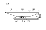
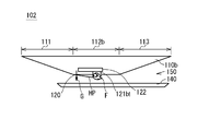
- FIGS. 2A to 3B are diagrams that are used for convenience to explain the matters recognized by the inventor. Therefore, FIGS. 2A to 3B do not show a known technique.
- FIGS. 1A and 1B are schematic cross-sectional views schematically showing the configuration of a jet engine to which the solution is applied.
- FIG. 2A shows a case where the flying speed is slow
- FIG. 2B shows a case where the flying speed is fast.
- the flame holder 121a is installed further downstream as compared with the jet engine 102 of FIGS. 1A and 1B.
- the length of the front part of the combustor 112a is longer than that of the flame holder 121a. This is because even when the flying speed is low, the length is set such that the high pressure region HP does not reach the inlet 111.
- this solution is a method of increasing the length of the front of the flame holder 121a and extending the entire length of the combustor 112a by that amount.
- FIGS. 1A and 1B are schematic cross-sectional views schematically showing the configuration of a jet engine to which the solution is applied.
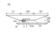
- FIG. 3A shows a case where the flying speed is slow
- FIG. 3B shows a case where the flying speed is fast.
- the flame holder 121b can change the position of the flame holder 121b in the combustor 112b in the front-rear direction (air flow direction).
- a device variable mechanism 122 is provided. That is, when the flying speed is slow (FIG. 3A), the flame holder 121b moves backward (flame holder 121b1). On the other hand, when the flying speed is high (FIG. 3B), the flame holder 121b moves forward (flame holder 121b2).
- the problem of the jet engine 102a of FIGS. 2A and 2B can be solved by changing the position of the flame holder 121b in accordance with the flying speed.
- the flame stabilizer variable mechanism 122 has a problem that a very large heat load accompanying combustion is applied.
- the problem that the fuselage 110b increases in size with the installation of the flame stabilizer variable mechanism 122 occurs.
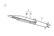
- FIG. 4 is a perspective view showing an example of the configuration of the flying object 1 according to the present embodiment.
- the flying body 1 includes a jet engine 2 and a rocket motor 3.
- the rocket motor 3 accelerates the flying object 1 from a speed at the start of flying to a desired speed when flying the flying object 1 from the launching device.
- the speed at the start of flying is zero when the flying object 1 is fired from a stationary launching device, and the flying object is moving / flying moving object / flying object.
- the jet engine 2 further accelerates the flying body 1 to fly toward the target.
- the jet engine 2 includes a body 10 and a cowl 40.
- the airframe 10 and the cowl 40 constitute an inlet, a combustor, and a nozzle of the jet engine 2 as described later.
- the jet engine 2 takes in air from the front at the inlet, mixes the air and fuel with the combustor, burns them, expands the combustion gas with the nozzles, and sends them back. Thereby, the jet engine 2 obtains a propulsive force.
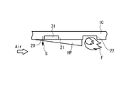
- FIG. 5A is a schematic sectional view schematically showing an example of the configuration of the jet engine according to the embodiment
- FIG. 5B is an enlarged view of the vicinity of the flame holder in FIG. 5A
- FIG. 5C is a perspective view of FIG. 5B.
- 5A to 5C show a case where the flying speed is slow (mainly during acceleration).
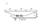
- FIG. 6A is a schematic sectional view schematically showing an example of the configuration of the jet engine according to the embodiment
- FIG. 6B is an enlarged view of the vicinity of the flame holder in FIG. 6A. 6A and 6B show the case where the flying speed is fast (mainly during cruising).
- the jet engine 2 includes a body 10 and a cowl 40 provided so as to form a space 50 through which gas can flow under the body 10.
- the lower part in front of the airframe 10 and the front part of the cowl 40 constitute an inlet 11 that introduces air into the space 50.
- the lower part in the middle of the fuselage 10 and the middle part of the cowl 40 constitute a combustor 12 that mixes and burns fuel and air.
- the lower part at the rear of the airframe 10 and the rear part of the cowl 40 constitute a nozzle 13 that expands and discharges combustion gas.
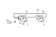
- the combustor 12 includes a fuel injector 20 and a plurality of flame holders 21 and 22.
- the fuel injector 20 is provided in a portion corresponding to the combustor 12 in the lower portion of the fuselage 10.
- the fuel injector 20 ejects the fuel G stored in the airframe 10 toward the space 50.
- the fuel G ejected from the fuel injector 20 is mixed with the air taken from the inlet 11.
- the air-fuel mixture is burned using a flame maintained by the flame holder 21, a flame maintained by the flame holder 22, or a flame maintained by the flame holder 21 and the flame holder 22.
- the fuel injector 20 is an opening provided in a lower portion of the fuselage 10, and the shape, number, and arrangement thereof are arbitrary.
- the fuel injector 20 is exemplified by a plurality of openings provided side by side in the span direction of the airframe 10 as shown in FIG. 5C.
- the flame holder 21 and the flame holder 22 are provided in a portion corresponding to the combustor 12 in the lower part of the fuselage 10.
- the flame holder 21 and the flame holder 22 are provided in this order along the flow direction of the mainstream air. That is, the flame holder 21 is a flame holder located on the side closer to the inlet, and the flame holder 22 is a flame holder located on the side far from the inlet. In other words, the distance between the flame holder 21 and the inlet is shorter than the distance between the flame holder 22 and the inlet.
- the flame holder 21 is, for example, the flame holder closest to the inlet among the plurality of flame holders.
- the flame holder 21 is near the fuel injector 20.
- a flame holder 22 is provided behind the flame holder 21.
- a part of the air taken in from the inlet 11 and a part of the fuel G from the fuel injector 20 are mixed and burned to form a flame F.
- the flame holder 21 and the flame holder 22 maintain the flame F.
- the flame F is used for combustion in the combustor 12.
- Each of the flame holder 21 and the flame holder 22 is a depression (or a depression) provided on the surface of the lower portion of the machine body 10, and the shape, number, and arrangement thereof are arbitrary.
- Each of the flame holder 21 and the flame holder 22 is exemplified by a groove provided so as to extend in the span direction of the airframe 10 as shown in FIG. 5C.
- the flame holder 21 is filled with the disappearing member 31, details of which will be described later.
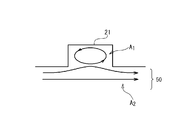
- FIG. 7 is a schematic cross-sectional view schematically showing an example of the configuration of the flame holder of the jet engine according to the embodiment.
- the flame holder 21 which is a dent (or a dent) provided on the surface of the machine body 10 can generate a low speed region A1 where a part of the air stays and becomes low speed. Since the air in the low speed region A1 is low speed, the air and the fuel G can be easily mixed and burned to generate and maintain the flame F. Therefore, it can be said that the flame holder 21 is a depression (or a depression) provided on the surface of the body 10 that can generate a low speed region A1 sufficient for flame holding.
- the speed of the air in the low speed region A1 is less than the propagation speed of the flame. That is, the speed of the air is slower than the propagation speed when the flame surface of the flame in the flame holder 21 propagates in the upstream direction or the downstream direction.
- the flame (flame F) in the flame holder 21 can spread and increase around.
- the flame F can propagate to the main flow (high-speed region A2) of the air and the fuel G outside the flame holder 21, and can assist combustion in the combustor 12. Therefore, the flame holders 21 and 22 can also be referred to as shapes that enable stable flame holding at a desired (designed) speed.
- the cross-sectional shape of the flame stabilizer 21 may be a rectangular shape as shown in FIG. 7, a trapezoidal shape, another polygonal shape, a curved surface shape such as a semicircle or a semi-ellipse, or a combination thereof. There may be.
- the recess (or recess) may be a groove extending in the entire span direction as shown in FIG. 5C, a groove extending partially in the span direction, or a plurality of recesses (or recesses). May be arranged along the span direction.
- No. 21 is initially filled with a disappearing member 31 in the recess (or recess) (FIGS. 5A to 5C). Therefore, initially, the flame holder 21 does not have the shape of the flame holder described above when the vanishing member 31 is included. Accordingly, initially, the flame F is formed only in the flame holder 22. Thereafter, the disappearing member 31 disappears with time during the flight of the flying object 1 (FIGS. 6A to 6B). As a result, after that, the flame F is also formed in the flame holder 21.
- the vanishing member 31 is a material that disappears due to thermal or aerodynamic influence after a certain period of time when accelerating from low speed to high speed while navigating in the jet engine 2. Specifically, the vanishing member 31 is changed in shape (melted, sublimated, burned, peeled, scraped, or some combination thereof) by the heat and pressure of air taken into the inlet 11. Material.
- the disappearing member 31 is a material that melts, sublimates, burns, scrapes, or peels off while the flying object 1 is in flight, but is preferably a material that does not ignite. It is because the load by heating is not given to the surrounding structure of the flame holder 21. As such a disappearing member, for example, an ablation material is preferable. This is because the ablation material cools the surrounding structural material by an endothermic reaction when disappearing, thereby reducing the thermal load.
- the ablation material is defined as a material that improves heat resistance by endotherm accompanying phase change.
- the disappearance of the disappearing member 31 if the flame holder 21 is in a state where it can function as a flame holder, the disappearing member 31 does not have to disappear completely, even if it remains partially. Good.
- the disappearance of the vanishing member 31 means that the vanishing member 31 is reduced so that the flame holder 21 can function as a flame holder, and the vanishing member 31 is not necessarily the flame holder 21. It is not necessary to disappear completely from the inside.
- FIG. 8 is a table showing an example of the vanishing member of the jet engine according to the present embodiment.
- the materials listed in this table are ablation materials. This table shows the relationship between the heating amount and shear force applied to these materials, and the shape disappearance rate of these materials.
- SkyHello registered trademark
- Silica / phenol is a phenolic resin containing silica fibers. It can be seen that the shape disappearing speed [unit: mm / second] varies depending on the type of material, the amount of heating applied to the material, and the shearing force.
- the shape disappearing speed can be arbitrarily adjusted by appropriately selecting the material based on the heating amount and shearing force assumed in the flame holder 21. That is, it is possible to arbitrarily adjust the transition time from the state of FIGS. 5A to 5C (low speed (acceleration)) to the state of FIGS. 6A to 6B (high speed (mainly during cruising)). .
- FIG. 9 shows the shape disappearance speed of the disappearing member required in various environments.
- the shape is changed (disappearing member 31 disappears) while the flight speed increases from 500 m / s (about Mach 1.7) to 1500 m / s (about Mach 5).
- Examples of the environment include airframe average acceleration and a necessary amount of shape change.
- the flame retainer 21 is filled with such a disappearing member 31 by being adhered with an adhesive, adhering with the tackiness of the disappearing member itself, or being pushed in.
- the vanishing member 31 only needs to disappear due to shape deformation during the flight of the flying body 1.
- a material having a desired melting point range such as a brazing material or a desired melting point such as an aluminum alloy is used.
- a range of metals may be used.
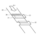
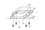
- the vanishing member 31 does not need to fill all the recesses of the flame holder 21 (FIGS. 5A to 5C), and may only cover the space 50 side of the flame holder 21. Such an example is shown in FIGS. 10 and 11.
- FIG. 10 and 11 are perspective views showing another configuration example of the disappearing member according to the present embodiment.
- the disappearing member 31 a includes a lid portion 32 and a support portion 33.
- the cover part 32 covers the dent of the flame holder 21a.
- the cover part 32 is provided in plate shape so that the space 50 side of the area
- the support part 33 supports the cover part 32 so that the cover part 32 is not recessed with respect to the recess of the flame holder 21.
- the support part 33 may have any shape, structure, number, and position as long as the cover part 32 is supported.
- the vanishing member 31 a is bonded to the inner surface of the flame holder 21 a on the side surface 32 a of the lid portion 32 and the upper surface 33 a of the support portion 33, for example, and coupled to the body 10.
- the cover part 32 is a vanishing member
- the support part 33 is a non-vanishing member.
- the support part 33 may be a vanishing member.
- the disappearing member 31 b includes a lid portion 32 and a plurality of screw members 34.
- the flame holder 21b is dropped into the space 50 so that the lid portion 32 can be placed thereon.
- the vanishing member 31b is coupled to the airframe 10 by, for example, fitting the lid portion 32 into the processed portion and screwing the screw member 34 into the screw hole 32c.
- the screw member 34 may not be used, and the side surface 32a and the upper surface 32b of the lid portion 32 may be bonded to the inner surface of the dropping portion of the flame holder 21b and coupled to the body 10.
- FIGS. 10 and 11 can make the disappearing member disappear in a very short time after a certain period of time. Therefore, it is suitable when it is desired to make the film thickness of the vanishing member thinner than the depth of the flame holder, or when it is desired to shorten the transition time during which the vanishing member gradually disappears.
- the flame holder 21 that is not used initially and the flame holder 22 that is continuously used are provided one by one, the present embodiment is not limited to this example. .
- the flame holders 22 start from the flame holder 22 side.
- the vanishing member may be selected so that the vanishing member disappears in order.
- the flame holder 21 can approach the fuel injector 20 side. Thereby, a jet engine can be used in a wider speed range.
- Flying object 1 is launched from the installation position toward the target.
- the rocket motor 3 accelerates the flying object 1 from a speed at the start of flying to a desired speed when flying the flying object 1 from the launching device.
- the speed at the start of flying is zero when the flying object 1 is launched from a stationary launching device, and the flying object is moving (or in flight) (or ,
- the flying speed of the moving object (or flying object) is the moving speed (or flying speed) of the moving object (or flying object).
- the flying body 1 separates the rocket motor 3 and accelerates by the jet engine 2 to fly.
- the flame holder 21 In the initial stage (at the time of acceleration) when acceleration is started by the jet engine 2, the speed of the flying object 1 is relatively low, and the flame holder 21 is filled with the disappearing member 31. That is, since the flame holder 21 does not form a “dent (or depression) that can generate a low speed region A1 sufficient for flame holding”, the flame holder 21 does not function as a flame holder. Therefore, the flame holder 21 does not have the flame F, and only the flame holder 22 maintains the flame F (FIGS. 5A to 5B).
- the speed of the flying object 1 increases as the jet engine 2 accelerates.
- the disappearing member 31 of the flame holder 21 is melted (or burned, sublimated, scraped, peeled off) by the heat of the air taken in from the inlet 11, and decreases with time.
- the flame holder 21 approaches a “dent (or depression) capable of generating a low speed region A1 sufficient for flame holding”. That is, the flame holder 21 gradually approaches a state where the function as a flame holder can be exhibited.
- the disappearing member 31 disappears.
- the flame holder 21 becomes a “dent (or depression) capable of generating a low speed region A1 sufficient for flame holding”. That is, the flame holder 21 is in a state where the function as a flame holder can be exhibited. Therefore, after that, the flame F is maintained not only by the flame holder 22 but also by the flame holder 21 (FIGS. 6A to 6B).
- the flying body 1 flies at a predetermined speed.
- the flying object 1 and the jet engine 2 according to the embodiment operate.
- the flame holder 21 is filled with the disappearing member 31 at the initial low speed (acceleration) when the jet engine 2 starts acceleration. Therefore, the flame holder 21 is not “a dent (or a depression) that can generate a low-speed region A1 sufficient for flame holding”, and the flame holder 21 does not have a function as a flame holder. That is, in the jet engine 2, only the flame holder 22 arranged at a position relatively distant from the inlet of the combustor 12 maintains the flame F (FIGS. 5A to 5B).
- the combustion pressure of the combustor 12 is relatively high, and the high pressure region HP spreads to the inlet 11 side, the inlet 11 never reach. That is, no backflow of fuel, air, or the like occurs, the flame F is maintained by the flame holder 22, and the engine does not stop.
- the combustor length in the combustor 12 is relatively short, but since the air velocity is slow, a sufficient combustion time can be taken and there is no problem in combustion.
- the flame holder 21 since the vanishing member 31 disappears at high speed (mainly during cruising) when the speed of the flying object 1 has increased, the flame holder 21 as a whole generates “a low-speed region A1 sufficient for flame holding. It can be a “dent (or dent)”. Therefore, the flame holder 21 has a function as a flame holder. That is, in the jet engine 2, the flame holder 21 disposed at a position relatively close to the inlet of the combustor 12 also maintains the flame F (FIGS. 6A to 6B).
- the dynamic pressure of the air taken from the inlet 11 at a high speed is relatively high, and the combustion pressure of the combustor 12 is relatively low, so that the high pressure region HP does not spread toward the inlet 11 side. That is, no reverse flow of fuel or the like occurs, the flame F is maintained by the flame holders 21 and 22, and the engine does not stop.
- the combustion length in the combustor 12 is relatively long, a sufficient combustion time can be taken even when the air velocity is high, and there is no problem in combustion.
- the combustor 12 is not lengthened and the nozzle is not enlarged, and compared with the conventional jet engine, the low speed region to the high speed region. It is possible to realize a flame holder that can be used in a very wide speed range. Thereby, the operating speed range of the jet engine 2 can be increased without significantly remodeling the airframe.
- the speed range that can be reached by the rocket motor 3 is increased by increasing the operable speed range of the jet engine 2 ( Since the speed range to be accelerated can be reduced, the size (weight) of the rocket motor 3 can be significantly reduced. As a result, the flying object 1 as a whole can be reduced in size and weight, and the acceleration performance can be further improved.
- the material, thickness, shape, etc. of the disappearing member it is possible to arbitrarily adjust the time required for changing the shape of the disappearing member (melting, sublimation, burning, scraping, peeling, etc.). Thereby, since the time to start using the flame stabilizer on the side close to the inlet can be arbitrarily adjusted, the jet engine can be used even from a very low speed region without the high pressure region reaching the inlet.
- the material of the disappearing member can change the shape of the disappearing member (melting, burning, scraping, peeling, etc.) so that no heat is generated or heat is absorbed from the surrounding structure, and the heat load on the surrounding structure is reduced. Can be reduced.
- Some embodiments describe examples in which a jet engine is applied to a flying object, but the embodiments are not limited to the examples, and can be applied to aircraft and rockets.
Landscapes
- Engineering & Computer Science (AREA)
- Chemical & Material Sciences (AREA)
- Combustion & Propulsion (AREA)
- Mechanical Engineering (AREA)
- General Engineering & Computer Science (AREA)
- Physics & Mathematics (AREA)
- Geometry (AREA)
- Testing Of Engines (AREA)
Priority Applications (2)
| Application Number | Priority Date | Filing Date | Title |
|---|---|---|---|
| EP15769123.9A EP3098429B1 (en) | 2014-03-28 | 2015-02-17 | Jet engine, flying body, and method for operating jet engine |
| US15/120,867 US10274199B2 (en) | 2014-03-28 | 2015-02-17 | Jet engine, flying object, and method of operating jet engine |
Applications Claiming Priority (2)
| Application Number | Priority Date | Filing Date | Title |
|---|---|---|---|
| JP2014-070205 | 2014-03-28 | ||
| JP2014070205A JP6268529B2 (ja) | 2014-03-28 | 2014-03-28 | ジェットエンジン、飛しょう体及びジェットエンジンの動作方法 |
Publications (1)
| Publication Number | Publication Date |
|---|---|
| WO2015146375A1 true WO2015146375A1 (ja) | 2015-10-01 |
Family
ID=54194911
Family Applications (1)
| Application Number | Title | Priority Date | Filing Date |
|---|---|---|---|
| PCT/JP2015/054301 Ceased WO2015146375A1 (ja) | 2014-03-28 | 2015-02-17 | ジェットエンジン、飛しょう体及びジェットエンジンの動作方法 |
Country Status (4)
| Country | Link |
|---|---|
| US (1) | US10274199B2 (enExample) |
| EP (1) | EP3098429B1 (enExample) |
| JP (1) | JP6268529B2 (enExample) |
| WO (1) | WO2015146375A1 (enExample) |
Cited By (4)
| Publication number | Priority date | Publication date | Assignee | Title |
|---|---|---|---|---|
| CN106121825A (zh) * | 2016-07-28 | 2016-11-16 | 西安航天动力试验技术研究所 | 发动机进气道堵盖及其开闭系统 |
| WO2017158856A1 (ja) * | 2016-03-16 | 2017-09-21 | 三菱重工業株式会社 | ジェットエンジン、および飛しょう体 |
| CN113006967A (zh) * | 2021-02-08 | 2021-06-22 | 中国人民解放军国防科技大学 | 一种火箭与前缘突扩凹腔组合的rbcc内流道 |
| US11248562B2 (en) | 2016-03-16 | 2022-02-15 | Mitsubishi Heavy Industries, Ltd. | Jet engine, flying object, and operation method of jet engine |
Families Citing this family (4)
| Publication number | Priority date | Publication date | Assignee | Title |
|---|---|---|---|---|
| JP6628246B2 (ja) * | 2016-03-28 | 2020-01-08 | 三菱重工業株式会社 | スクラムジェットエンジン、飛しょう体 |
| US11415080B2 (en) * | 2018-05-14 | 2022-08-16 | General Electric Company | Engine for an aircraft |
| CN113720611B (zh) * | 2021-06-25 | 2022-07-26 | 蓝箭航天空间科技股份有限公司 | 运载火箭起飞推力模拟加载装置 |
| CN114440259B (zh) * | 2021-12-14 | 2023-01-17 | 西安航天动力研究所 | 一种多路供油的拼接式火焰稳定装置 |
Citations (6)
| Publication number | Priority date | Publication date | Assignee | Title |
|---|---|---|---|---|
| US3667233A (en) * | 1969-11-14 | 1972-06-06 | Us Air Force | Dual mode supersonic combustion ramjet engine |
| US5174524A (en) * | 1991-10-10 | 1992-12-29 | General Electric Company | Cooling system for high speed aircraft |
| JP3032377B2 (ja) * | 1992-06-05 | 2000-04-17 | ダイセル化学工業株式会社 | ラムジェットエンジンの点火手段 |
| US6293091B1 (en) * | 1999-04-22 | 2001-09-25 | Trw Inc. | Axisymmetrical annular plug propulsion system for integrated rocket/ramjet or rocket/scramjet |
| JP2012207610A (ja) * | 2011-03-30 | 2012-10-25 | Mitsubishi Heavy Ind Ltd | スクラムジェットエンジン |
| JP2012207555A (ja) * | 2011-03-29 | 2012-10-25 | Mitsubishi Heavy Ind Ltd | スクラムジェットエンジン |
Family Cites Families (6)
| Publication number | Priority date | Publication date | Assignee | Title |
|---|---|---|---|---|
| US2989922A (en) * | 1953-02-17 | 1961-06-27 | Marvin H Greenwood | Ramjet propulsion device |
| US3074668A (en) * | 1958-12-10 | 1963-01-22 | Snecma | Burner for hot fuel |
| US4628688A (en) * | 1983-08-29 | 1986-12-16 | The United States Of America As Represented By The Secretary Of The Navy | Solid fuel ramjet flow control device |
| FR2661454B1 (fr) * | 1985-07-12 | 1994-02-11 | Onera | Perfectionnements apportes aux propulseurs de type statoreacteur. |
| JPH09250395A (ja) | 1996-03-18 | 1997-09-22 | Ishikawajima Harima Heavy Ind Co Ltd | ジェットエンジンの可変式フレームホルダ |
| US6739121B2 (en) * | 2002-01-22 | 2004-05-25 | Environmental Areoscience Corp. | Flame holder for a hybrid rocket motor |
-
2014
- 2014-03-28 JP JP2014070205A patent/JP6268529B2/ja active Active
-
2015
- 2015-02-17 US US15/120,867 patent/US10274199B2/en active Active
- 2015-02-17 EP EP15769123.9A patent/EP3098429B1/en active Active
- 2015-02-17 WO PCT/JP2015/054301 patent/WO2015146375A1/ja not_active Ceased
Patent Citations (6)
| Publication number | Priority date | Publication date | Assignee | Title |
|---|---|---|---|---|
| US3667233A (en) * | 1969-11-14 | 1972-06-06 | Us Air Force | Dual mode supersonic combustion ramjet engine |
| US5174524A (en) * | 1991-10-10 | 1992-12-29 | General Electric Company | Cooling system for high speed aircraft |
| JP3032377B2 (ja) * | 1992-06-05 | 2000-04-17 | ダイセル化学工業株式会社 | ラムジェットエンジンの点火手段 |
| US6293091B1 (en) * | 1999-04-22 | 2001-09-25 | Trw Inc. | Axisymmetrical annular plug propulsion system for integrated rocket/ramjet or rocket/scramjet |
| JP2012207555A (ja) * | 2011-03-29 | 2012-10-25 | Mitsubishi Heavy Ind Ltd | スクラムジェットエンジン |
| JP2012207610A (ja) * | 2011-03-30 | 2012-10-25 | Mitsubishi Heavy Ind Ltd | スクラムジェットエンジン |
Cited By (6)
| Publication number | Priority date | Publication date | Assignee | Title |
|---|---|---|---|---|
| WO2017158856A1 (ja) * | 2016-03-16 | 2017-09-21 | 三菱重工業株式会社 | ジェットエンジン、および飛しょう体 |
| US11248562B2 (en) | 2016-03-16 | 2022-02-15 | Mitsubishi Heavy Industries, Ltd. | Jet engine, flying object, and operation method of jet engine |
| CN106121825A (zh) * | 2016-07-28 | 2016-11-16 | 西安航天动力试验技术研究所 | 发动机进气道堵盖及其开闭系统 |
| CN106121825B (zh) * | 2016-07-28 | 2018-03-13 | 西安航天动力试验技术研究所 | 发动机进气道堵盖及其开闭系统 |
| CN113006967A (zh) * | 2021-02-08 | 2021-06-22 | 中国人民解放军国防科技大学 | 一种火箭与前缘突扩凹腔组合的rbcc内流道 |
| CN113006967B (zh) * | 2021-02-08 | 2022-04-19 | 中国人民解放军国防科技大学 | 一种火箭与前缘突扩凹腔组合的rbcc内流道 |
Also Published As
| Publication number | Publication date |
|---|---|
| JP6268529B2 (ja) | 2018-01-31 |
| JP2015190740A (ja) | 2015-11-02 |
| EP3098429B1 (en) | 2018-12-12 |
| EP3098429A1 (en) | 2016-11-30 |
| US10274199B2 (en) | 2019-04-30 |
| US20160363318A1 (en) | 2016-12-15 |
| EP3098429A4 (en) | 2017-03-22 |
Similar Documents
| Publication | Publication Date | Title |
|---|---|---|
| JP6268529B2 (ja) | ジェットエンジン、飛しょう体及びジェットエンジンの動作方法 | |
| JP6719933B2 (ja) | ジェットエンジン、飛しょう体、および、ジェットエンジンの動作方法 | |
| US10830439B2 (en) | Jet engine, flying object, and method of operating a jet engine | |
| EP3098428B1 (en) | Combustor, jet engine, flying body, and method for operating the jet engine | |
| JP6204250B2 (ja) | ジェットエンジン、飛しょう体及びジェットエンジンの動作方法 | |
| WO2015151621A1 (ja) | ジェットエンジン、飛しょう体及びジェットエンジンの動作方法 | |
| RU2482031C2 (ru) | Устройство уменьшения аэродинамического сопротивления | |
| JP6037818B2 (ja) | ジェットエンジン | |
| JP6310293B2 (ja) | 燃焼器、ジェットエンジン、飛しょう体及びジェットエンジンの動作方法 | |
| WO2017158856A1 (ja) | ジェットエンジン、および飛しょう体 | |
| JP6016616B2 (ja) | ジェットエンジン | |
| WO2013001267A1 (en) | A bomb for deployment from an air vehicle | |
| Dirscherl et al. | Hypersonic Speed Through Scramjet Technology | |
| JP2014190583A (ja) | 飛しょう体 |
Legal Events
| Date | Code | Title | Description |
|---|---|---|---|
| 121 | Ep: the epo has been informed by wipo that ep was designated in this application |
Ref document number: 15769123 Country of ref document: EP Kind code of ref document: A1 |
|
| REEP | Request for entry into the european phase |
Ref document number: 2015769123 Country of ref document: EP |
|
| WWE | Wipo information: entry into national phase |
Ref document number: 2015769123 Country of ref document: EP |
|
| WWE | Wipo information: entry into national phase |
Ref document number: 15120867 Country of ref document: US |
|
| NENP | Non-entry into the national phase |
Ref country code: DE |