WO2015146361A1 - Curtain air bag system - Google Patents
Curtain air bag system Download PDFInfo
- Publication number
- WO2015146361A1 WO2015146361A1 PCT/JP2015/054117 JP2015054117W WO2015146361A1 WO 2015146361 A1 WO2015146361 A1 WO 2015146361A1 JP 2015054117 W JP2015054117 W JP 2015054117W WO 2015146361 A1 WO2015146361 A1 WO 2015146361A1
- Authority
- WO
- WIPO (PCT)
- Prior art keywords
- vehicle
- wall portion
- cushion
- cover member
- rib
- Prior art date
Links
Images


Classifications
-
- B—PERFORMING OPERATIONS; TRANSPORTING
- B60—VEHICLES IN GENERAL
- B60R—VEHICLES, VEHICLE FITTINGS, OR VEHICLE PARTS, NOT OTHERWISE PROVIDED FOR
- B60R21/00—Arrangements or fittings on vehicles for protecting or preventing injuries to occupants or pedestrians in case of accidents or other traffic risks
- B60R21/02—Occupant safety arrangements or fittings, e.g. crash pads
- B60R21/16—Inflatable occupant restraints or confinements designed to inflate upon impact or impending impact, e.g. air bags
- B60R21/20—Arrangements for storing inflatable members in their non-use or deflated condition; Arrangement or mounting of air bag modules or components
- B60R21/213—Arrangements for storing inflatable members in their non-use or deflated condition; Arrangement or mounting of air bag modules or components in vehicle roof frames or pillars
-
- B—PERFORMING OPERATIONS; TRANSPORTING
- B60—VEHICLES IN GENERAL
- B60R—VEHICLES, VEHICLE FITTINGS, OR VEHICLE PARTS, NOT OTHERWISE PROVIDED FOR
- B60R21/00—Arrangements or fittings on vehicles for protecting or preventing injuries to occupants or pedestrians in case of accidents or other traffic risks
- B60R21/02—Occupant safety arrangements or fittings, e.g. crash pads
- B60R21/16—Inflatable occupant restraints or confinements designed to inflate upon impact or impending impact, e.g. air bags
- B60R21/20—Arrangements for storing inflatable members in their non-use or deflated condition; Arrangement or mounting of air bag modules or components
- B60R21/215—Arrangements for storing inflatable members in their non-use or deflated condition; Arrangement or mounting of air bag modules or components characterised by the covers for the inflatable member
- B60R2021/21512—Arrangements for storing inflatable members in their non-use or deflated condition; Arrangement or mounting of air bag modules or components characterised by the covers for the inflatable member the lid being displaced towards the occupant during deployment
Definitions
- the present invention includes a cushion part that inflates and expands along a side part in a vehicle compartment for the purpose of protecting an occupant at the time of a side collision or rollover (rollover) of a vehicle, and a cover member attached to the cushion part.
- the present invention relates to a curtain airbag device.
- An airbag is a safety device that operates in an emergency such as a vehicle collision, and inflates and deploys with gas pressure to receive and protect an occupant.
- An airbag is a safety device that operates in an emergency such as a vehicle collision, and inflates and deploys with gas pressure to receive and protect an occupant.
- airbags There are various types of airbags depending on the installation location and application.
- a front airbag is provided in the center of the steering wheel in order to protect the driver from collisions in the front-rear direction.
- a curtain airbag device having a cushion portion that inflates and deploys along the side window is provided in the vicinity of the ceiling of the side wall of the vehicle body in order to protect an occupant from a side collision and subsequent rollover (rollover). .
- the cushion portion of the curtain airbag device has a large shape that covers a side window or the like of the side wall of the vehicle body, and is mounted on the upper side of the vehicle body side wall in a slender storage form that is wound or folded from below.
- Patent Document 1 describes a curtain airbag device provided with a cover member that is attached to a part of a cushion portion and accommodates the folded cushion portion.
- the cover member includes a connection wall that connects a pair of opposing walls, a load transmission portion provided on the connection wall, and a locking portion that is disposed on the vehicle exterior side of the load transmission portion.
- Patent Document 1 when an operator presses the load transmission portion from the vehicle inner side toward the vehicle outer side (roof side rail side), the pressing load is efficiently transmitted to the locking portion via the load transmission portion, and the curtain airbag The device can be easily assembled to the roof side rail.
- the cover member not only holds the cushion portion in the storage form during normal times, but also has a role that enables the cushion portion to smoothly expand and deploy in an emergency.
- the cushion portion can be deployed in a target direction by obtaining a reaction force from the cover member during inflated deployment.
- the cover member may be deformed by receiving a force from the cushion part during expansion and deployment. If the cover member is deformed, the cushion part is hung on a member on the side wall of the vehicle body at the time of inflating and deploying, so that the unfolding behavior is hindered and the cushion part may be unfolded in a direction other than the target direction. For this reason, the cover member is required to have rigidity in order to suppress deformation at the time of expansion and deployment of the cushion portion.
- Patent Document 1 only describes a configuration in which a curtain airbag device is easily assembled to a roof side rail, and achieves both the purpose of not hindering the deployment behavior of the cushion portion and the purpose of maintaining occupant protection performance. I can't let you.
- the present invention provides a curtain airbag device that not only inhibits the deployment behavior of the cushion portion during inflation and deployment, but also maintains the occupant protection performance when the occupant's head collides.
- the purpose is that.
- a typical configuration of a curtain airbag device according to the present invention is configured in a bag shape and is wound or folded so as to have an elongated storage form and is mounted on an upper portion of a vehicle body side wall.
- a curtain airbag device including a cushion part and a cover member attached to the cushion part, the cover member being located on the vehicle outer side of the cushion part in the storage form, and extending outside in the vehicle vertical direction
- a lower side wall portion that is inclined and extends downward from the lower end of the wall portion toward the lower side of the vehicle interior, and extends downward from the vicinity of the end portion of the lower side wall portion on the inner side of the vehicle,
- a first vertical wall portion facing the interior material on the vehicle exterior side of the interior material covering the vehicle interior of the side wall; and a rib provided on the opposite side to the side where the cushion portion is installed with respect to the outer wall portion and the lower wall portion;
- the lower side wall portion of the cover member receives force from the cushion portion during expansion and deployment. If the lower side wall portion is deformed by receiving a force from the cushion portion, the cushion portion may be caught between the side wall of the vehicle body and the interior material, and may expand in a direction other than the target direction. For this reason, the lower side wall portion of the cover member is required to have rigidity in order to suppress deformation at the time of expansion and deployment of the cushion portion.
- the impact is transmitted to the interior material through the cushion part.
- the interior material is deformed to the outside of the vehicle and presses the lower side wall portion of the cover member. If the lower wall portion pressed against the interior material is not deformed at all, the occupant's head receives a large reaction force from the lower wall portion via the interior material and the cushion portion.
- ribs are formed on the side opposite to the side where the cushion portion is installed with respect to the outer wall portion and the lower wall portion of the cover member. For this reason, the rigidity of the outer side wall part and lower side wall part of a cover member is ensured, and the deformation
- the above ribs may be erected from the vehicle outer side of the gap portion to the vehicle outer side of the outer wall portion. Thus, the rib is not formed in the gap.
- the above-mentioned gap portion may be constituted by a non-connection region where the first vertical wall portion and the rib are not connected, or may be a predetermined region extending from the first vertical wall portion to the vehicle outer side. As described above, the gap portion is located between the first wall portion and the rib and is a region where no rib is formed.
- the above cover member may further include a second vertical wall portion that extends downward from the lower side of the lower wall portion and divides the vehicle exterior side of the gap portion.
- the rib does not need to be in contact with the second vertical wall portion, but as an example, the second vertical wall portion and the rib may be joined. At this time, the second vertical wall portion may partition the outer side of the gap portion by contacting the rib on the inner side of the rib.
- the rib includes a lower region located on the vehicle outer side of the second vertical wall portion, and the first dimension in the vehicle width direction of the gap is smaller than the second dimension that is the length of the lower region in the vehicle width direction. Good.
- the lower region is located on the vehicle lower side of the lower side wall portion, and is formed longer in the vehicle width direction than the gap portion. For this reason, in the cover member, even if the gap portion is formed, the rigidity of the lower side wall portion can be secured by the lower region.
- the cover member may further include a partition wall that extends from the base of the second vertical wall portion toward the vehicle outer side in the vehicle width direction and further extends downward to partition the lower region from the rib.
- a partition wall that extends from the base of the second vertical wall portion toward the vehicle outer side in the vehicle width direction and further extends downward to partition the lower region from the rib.
- the cover member can increase the rigidity of the lower side wall portion.
- the curtain airbag apparatus which not only does not inhibit the deployment behavior at the time of inflating and deploying the cushion portion but also can maintain the occupant protection performance when the occupant's head collides. .
- FIG.3 It is a figure which illustrates the curtain airbag apparatus concerning embodiment of this invention. It is a figure which expands and illustrates the cover member vicinity of FIG. It is each sectional drawing of the cover member and cushion part of FIG. It is a figure which illustrates the state which the passenger
- DESCRIPTION OF SYMBOLS 100 Air bag, 102 ... Cushion part, 102A ... A part of cushion part, 104 ... Roof side rail, 106 ... Vehicle, 108 ... Roof trim, 110 ... Inflator, 112 ... Side window, 114 ... Front seat, 116, 118, 122 ... Chamber, 120 ... Rear seat, 124 ... Upper edge, 126 ... Mounting tab, 128 ... Strap, 130 ... Front pillar, 132 ... Center pillar, 140 ... Cover member, 142a, 142b ... Hole, 144 ... Pillar Garnish, 146 ... outer wall portion, 148 ... lower wall portion, 150 ... first vertical wall portion, 152 ... rib, 154 ... gap portion, 156 ... lower region, 158 ... part of rib, 160 ... second vertical wall portion 164 ... partition wall, 166 ... root, 168 ... occupant, 170 ... head
- FIG. 1 is a diagram illustrating a curtain airbag device (hereinafter, airbag 100) according to an embodiment of the present invention.
- FIGS. 1A and 1B are views of the interior of a vehicle as viewed from the inside of the vehicle in the vehicle width direction, illustrating the storage configuration of the cushion portion 102 of the airbag 100 and the state when inflated and deployed, respectively. .
- the cushion part 102 is a part that inflates and deploys to protect the occupant in an emergency. As illustrated in FIG. 1A, the cushion portion 102 is wound around in a normal state and has a long and narrow roll-shaped storage configuration in the front and rear of the vehicle, and is attached to the upper portion of the vehicle body side wall (the roof side rail 104). 106. The roof side rail 104 is usually covered with a roof trim 108 (see FIG. 3). For this reason, the mounted cushion part 102 is invisible from the vehicle compartment.
- the storage form of the cushion part 102 can also be realized by folding.
- the upper part of the cushion part 102 is provided with, for example, a cylinder type (cylinder type) inflator 110 which is a gas generator.
- the cushion part 102 expand
- Inflators that are currently popular are types that are filled with a gas generating agent and burn it to generate gas, types that are filled with compressed gas and supply gas without generating heat, and There are types including both a gas generating agent and a compressed gas. Any type of inflator 110 can be used.
- a sensor (not shown) provided in the vehicle 106 senses an impact, resulting in this.
- a signal is transmitted to the inflator 110.
- the inflator 110 operates and gas is supplied to the cushion portion 102.
- the cushion portion 102 is directed downward along the side wall of the passenger compartment (such as the side window 112 in FIG. 1A) as illustrated in FIG. 1B. Inflate and deploy to protect passengers.
- the cushion portion 102 has a large shape that can be expanded along the side surface of the passenger compartment as a curtain airbag.
- the cushion portion 102 is formed in a bag shape by overlapping two base fabrics constituting the surface thereof, sewing and bonding, or spinning using OPW (One-Piece Woven).
- the expansion region of the cushion portion 102 is partitioned into a plurality of small rooms (chambers) in consideration of the position where the occupant can come into contact.
- chambers 116 and 118 are provided on the front side of the vehicle for the purpose of receiving the occupant of the front seat 114.
- a chamber 122 and the like are provided on the side of the rear seat 120 on the rear side of the vehicle.
- a plurality of attachment tabs 126 as attachment portions to the vehicle 106 are provided on the upper edge 124 of the cushion portion 102.
- the attachment tab 126 has a belt shape and is attached to the roof side rail 104 using a bolt or the like.
- a string-like strap 128 is provided at the front end of the cushion portion 102.
- the strap 128 is a member that connects the cushion portion 102 to the front pillar 130, suppresses the swinging of the cushion portion 102 during expansion and deployment, stabilizes the deployment behavior, and gives the cushion portion 102 tension in the vehicle longitudinal direction. .
- the airbag 100 includes a cover member 140 attached in the vicinity of the center pillar 132 (see FIG. 3) in the cushion portion 102.
- the cover member 140 is fixed to the roof side rail 104 at the top of the center pillar 132 using a bolt (not shown) inserted through the holes 142a and 142b (see FIG. 2).
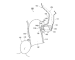
- FIG. 2 is an enlarged view illustrating the vicinity of the cover member 140 of FIG.
- FIG. 2A is a view of the cover member 140 holding the cushion portion 102 in the storage form as seen from the vehicle outer side in the vehicle width direction.
- FIG. 2B is a view as seen from an arrow A in FIG.
- FIG. 3 is a cross-sectional view of the cover member 140 and the cushion portion 102 of FIG. 2, and illustrates the roof trim 108, the center pillar 132, and the pillar garnish 144.
- FIG. 3A is a cross-sectional view taken along the line BB in FIG.
- FIG. 3B is a cross-sectional view illustrating a state in which the cushion portion 102 of FIG.
- the cover member 140 is made of resin, and has a long shape along the storage-type cushion portion 102 as illustrated in FIGS. 2A and 2B, and the storage-type cushion portion 140 102 covers, for example, the vehicle body side wall (the vehicle outer side) and the vehicle lower side. Moreover, the vehicle inner side of the cushion part 102 is covered with the roof trim 108 so that it may illustrate in Fig.3 (a).
- a pillar garnish 144 is disposed below the roof trim 108.
- the pillar garnish 144 is an interior material that covers the inside of the vehicle body side wall, and an upper end 144a of the pillar garnish 144 is in contact with the lower end 108a of the roof trim 108 from the inside of the vehicle.
- the cover member 140 includes an outer wall portion 146, a lower wall portion 148, a first vertical wall portion 150, and a rib 152, as illustrated in FIG.
- the outer side wall part 146 is located on the vehicle outer side of the cushion part 102 in the storage form, and extends in the vehicle vertical direction.
- the lower wall portion 148 extends from the vicinity of the lower end 146a of the outer wall portion 146 in an inclined manner toward the lower inside of the vehicle, and is positioned below the cushion portion 102.
- the first vertical wall portion 150 extends downward from the vicinity of the end portion 148a on the vehicle inner side of the lower wall portion 148.
- the first vertical wall portion 150 faces the pillar garnish 144 on the outside of the pillar garnish 144 with the lower end 108a of the roof trim 108 interposed therebetween.
- the ribs 152 are opposite to the outer wall portion 146 and the lower wall portion 148 on the opposite side where the stored cushion portion 102 is installed, that is, on the vehicle outer side of the outer wall portion 146 and the vehicle lower side of the lower wall portion 148. Is provided. Further, the cover member 140 has a gap portion 154 between the first vertical wall portion 150 and the rib 152 below the lower wall portion 148.
- the gap portion 154 is a predetermined region extending from the first vertical wall portion 150 to the vehicle outer side, and is located between the first wall portion 150 and the rib 152 and is a region where the rib 152 is not formed. Or the space
- the rib 152 is erected from the vehicle outer side of the gap portion 154, which is a predetermined region extending from the first vertical wall portion 150 to the vehicle outer side, on the vehicle lower side of the lower wall portion 148, from the vehicle outer side of the outer wall portion 146. Yes. That is, as illustrated in FIG. 3A, the rib 152 has a first dimension L ⁇ b> 1 indicating the length in the vehicle width direction from the first vertical wall 150 to the outside of the vehicle below the lower wall 148.
- the gap 154 is not formed.
- the rib 152 includes a lower region 156 located on the vehicle outer side of the gap portion 154. Furthermore, at least a part 158 of the rib 152 that is erected on the vehicle outer side from the outer wall portion 146 is in contact with the body panel (the side wall of the vehicle body).
- the cover member 140 includes a second vertical wall portion 160 and a partition wall 164.
- the second vertical wall portion 160 extends downward from the lower side wall portion 148 and is formed at a position separating the gap portion 154 from the first vertical wall portion 150.
- the second vertical wall portion 160 is in contact with the lower region 156 on the inner side of the lower region 156, thereby defining the outer side of the gap portion 154. That is, the lower region 156 is located on the vehicle exterior side of the gap portion 154 and the second vertical wall portion 160.
- the partition wall 164 extends from the base 166 of the second vertical wall portion 160 toward the vehicle outer side in the vehicle width direction, and further extends downward to partition the lower region 156 from the rib 152.
- the first dimension L1 is the length in the vehicle width direction of the gap portion 154, that is, the length in the vehicle width direction of the interval between the first vertical wall portion 150 and the second vertical wall portion 160. As illustrated in FIG. 3A, in the cover member 140, the first dimension L1 is smaller than the second dimension L2.
- the cover member 140 not only holds the cushion portion 102 in the storage form in a normal state, but also has a role to enable the cushion portion 102 to smoothly expand and deploy in an emergency.
- the cushion portion 102 inflates and expands in the passenger compartment space over the upper end 144a of the pillar garnish 144 while pushing the roof trim 108 away.
- the lower wall portion 148 of the cover member 140 receives a force from the cushion portion 102 that expands and deploys.
- the lower wall portion 148 is deformed by receiving a force from the cushion portion 102, the cushion portion 102 is caught, for example, between the center pillar 132 and the pillar garnish 144 (see FIG. 6B). There is a risk of deployment in directions other than the intended direction. Therefore, the lower side wall portion 148 of the cover member 140 is required to have rigidity in order to suppress deformation of the cushion portion 102 during expansion and deployment.
- the rib 152 is formed on the opposite side of the cover member 140 where the cushioned portion 102 is placed with respect to the outer wall portion 146 and the lower wall portion 148.
- a rib 152 including a lower region 156 is formed on the lower side wall portion 148.
- FIG. 4 is a diagram illustrating a state in which the head 170 of the occupant 168 collides with the cushion portion 102 after inflated and deployed from the state of FIG.
- the impact is transmitted to the pillar garnish 144 via the cushion portion 102.
- the pillar garnish 144 subjected to the impact is deformed to the outside of the vehicle and presses the lower side wall portion 148 of the cover member 140.
- the cover member 140 can avoid the poor deployment of the cushion portion 102 only by securing the rigidity of the lower side wall portion 148, but cannot absorb the impact when the head 170 of the occupant 168 collides, and occupant protection performance. Will be damaged.
- the rib 152 is not formed from the first vertical wall portion 150 to a predetermined region outside the vehicle, and the gap is formed between the first vertical wall portion 150 and the lower region 156 of the rib 152.
- a configuration forming part 154 was adopted.
- the first vertical wall portion 150 is first pressed against the pillar garnish 144.
- the first vertical wall portion 150 can be deformed to the vehicle outer side using the gap portion 154 until it abuts on the second vertical wall portion 160 in contact with the lower region 156 on the vehicle inner side of the lower region 156.
- the first vertical wall 150 can be deformed by the following modifications, as illustrated by the phantom line in FIG. 3B and the solid line in FIG. That is, the range from the root 166 of the second vertical wall portion 160 to the end portion 148a on the vehicle inner side of the lower wall portion 148 is made possible by displacing counterclockwise from the root 166 toward the vehicle outer side.
- the first vertical wall portion 150 of the lower wall portion 148 can absorb the impact by being deformed to the vehicle outer side when the head 170 of the occupant 168 collides with the cushion portion 102. For this reason, the head 170 of the occupant 168 does not receive a large reaction force, and the occupant protection performance is not impaired. That is, the cover member 140 enables the first vertical wall portion 150 to be deformed to the vehicle outer side while ensuring the rigidity of the lower wall portion 148.
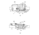
- FIG. 5 is an enlarged view illustrating the vicinity of the cover member 140A of the airbag 200 of the comparative example.
- FIG. 5A is a view of the cover member 140A holding the cushion portion 102 in the storage form as viewed from the vehicle outer side in the vehicle width direction.
- FIG.5 (b) is a C arrow directional view of Fig.5 (a).
- 6 is a cross-sectional view of the cover member 140A and the cushion portion 102 of FIG.
- FIG. 6A is a DD cross-sectional view of FIG.
- FIG. 6B is a cross-sectional view illustrating a state where the cushion portion 102 of FIG. 6A is inflated and deployed in an emergency.
- the airbag 200 of the comparative example includes an outer wall portion 202 positioned on the vehicle outer side of the cushion portion 102 in a stored state, and a lower side wall portion 204 positioned on the lower side of the cushion portion 102. And a vertical wall portion 206 and a wall portion 208.
- the airbag 200 is different from the airbag 100 in that a rib 210 is erected on the vehicle outer side of the outer wall portion 202, but no rib is formed on the vehicle lower side of the lower wall portion 204.
- the lower wall portion 204 extends from the lower end 202a of the outer wall portion 202 in an inclined manner downward on the vehicle inner side.
- the vertical wall portion 206 extends downward from an end portion 204 a on the vehicle inner side of the lower wall portion 204.
- the vertical wall portion 206 faces the pillar garnish 144 on the outside of the pillar garnish 144 with the lower end 108a of the roof trim 108 interposed therebetween.
- the wall 208 divides the outer wall 202 and the lower wall 204 and extends from the lower end 202a of the outer wall 202 toward the vehicle exterior.
- the end 208 a of the wall 208 on the vehicle exterior side is in contact with the center pillar 132 together with the rib 210.
- the airbag 200 it is possible to prevent the outer wall portion 202 of the cover member 140A from being deformed to the vehicle outer side when the cushion portion 102 is inflated and deployed.
- the lower side wall portion 204 of the cover member 140A has no rib formed on the lower side of the vehicle, and thus cannot secure rigidity.
- the lower wall portion 204 is a vertical wall starting from the lower end 202a of the outer wall portion 202 as illustrated by the phantom line and the arrow E in FIG. Together with the portion 206, it is displaced counterclockwise toward the vehicle exterior.
- the cover member 140A when the lower wall portion 204 and the vertical wall portion 206 receive a force from the cushion portion 102 that expands and deploys in an emergency, the cover member 140A is deformed as indicated by a solid line in the drawing. To do. For this reason, for example, a gap 212 is generated between the center pillar 132 and the pillar garnish 144, more specifically between the vertical wall portion 206 and the pillar garnish 144.
- a part 102A of the cushion portion 102 may be caught in the gap 212 at the time of inflation and deployment, and the deployment behavior may be hindered and deployed in a direction other than the target direction. is there.
- the first vertical wall portion 150 can be deformed to the vehicle outer side while the rigidity of the lower wall portion 148 of the cover member 140 is ensured.
- the deployment behavior of the portion 102 is not hindered, and further, the passenger protection performance can be maintained.
- the lower wall portion 148 of the cover member 140 is deformed to the vehicle exterior until the first vertical wall portion 150 comes into contact with the second vertical wall portion 160 and is not further deformed, so that rigidity can be ensured. Since the first dimension L1 that is the length of the gap 154 in the vehicle width direction is smaller than the second dimension L2 that is the length of the lower area 156 in the vehicle width direction, the lower area 156 is wider than the gap 154 in the vehicle width. It is long in the direction. For this reason, the cover member 140 can ensure the rigidity of the lower wall portion 148 even if the gap portion 154 is formed.
- a part 158 of the rib 152 is in contact with the body panel. For this reason, in the cover member 140, the outer wall portion 146 is hardly deformed to the vehicle outer side when the cushion portion 102 is inflated and deployed, and the deformation of the lower wall portion 148 continuous with the outer wall portion 146 is further suppressed.
- the vehicle lower side of the lower wall portion 148 is reinforced by the partition wall 164 in addition to the second vertical wall portion 160 and the lower region 156. For this reason, in the cover member 140, the lower side wall part 148 becomes more difficult to deform when the cushion part 102 is inflated and deployed, and rigidity can be ensured even if the gap part 154 is formed.
- the present invention includes a cushion part that inflates and expands along a side part in a vehicle compartment for the purpose of protecting an occupant at the time of a side collision or rollover (rollover) of a vehicle, and a cover member attached to the cushion part. It can be used for a curtain airbag device.
Abstract
[Problem] To provide a curtain air bag system that not only does not hinder the deployment action when a cushion part is expandably deployed, but can also maintain occupant-protective performance when the head of an occupant collides. [Solution] A curtain air bag system (100) is provided with a cushion part (102) installed in an upper part of a body side wall and stored in a long, thin form, and a cover member (140) attached to the cushion part, the cover member being provided with: an outer side wall part (146) positioned on the vehicular outer side of the stored cushion part; a lower side wall part (148) inclined downward toward the vehicular inner side from near the lower end of the outer side wall part, the lower side wall part being positioned on a side below the cushion part; a first vertical wall part (150) extending downward from near the vehicular-inner-side end of the lower side wall part and facing a pillar garnish (144) for covering the vehicular inner side of the body side wall, the first vertical wall part facing the pillar garnish from the vehicular outer side thereof; and a rib (152) provided on the side of the outer side wall part and the lower side wall part opposite the side where the cushion part is installed, and the cover member having a cavity part (154) between the first vertical wall part and the rib below the lower side wall part.
Description
本発明は、車両の側面衝突時やロールオーバ(横転)時に、乗員保護を目的として車両室内の側面部に沿うように膨張展開するクッション部と、クッション部に取付けられたカバー部材とを備えたカーテンエアバッグ装置に関するものである。
The present invention includes a cushion part that inflates and expands along a side part in a vehicle compartment for the purpose of protecting an occupant at the time of a side collision or rollover (rollover) of a vehicle, and a cover member attached to the cushion part. The present invention relates to a curtain airbag device.
近年の車両にはエアバッグがほぼ標準装備されている。エアバッグは、車両衝突などの緊急時に作動する安全装置であって、ガス圧で膨張展開して乗員を受け止めて保護する。エアバッグには、設置箇所や用途に応じて様々な種類がある。例えば、前後方向からの衝突から運転者を守るために、ステアリングの中央にはフロントエアバッグが設けられている。また、側面衝突やそれに続いて起こるロールオーバ(横転)から乗員を守るために、車体側壁の天井付近にはサイドウィンドウに沿って膨張展開するクッション部を備えたカーテンエアバッグ装置が設けられている。
Modern vehicles are almost equipped with airbags as standard. An airbag is a safety device that operates in an emergency such as a vehicle collision, and inflates and deploys with gas pressure to receive and protect an occupant. There are various types of airbags depending on the installation location and application. For example, a front airbag is provided in the center of the steering wheel in order to protect the driver from collisions in the front-rear direction. In addition, a curtain airbag device having a cushion portion that inflates and deploys along the side window is provided in the vicinity of the ceiling of the side wall of the vehicle body in order to protect an occupant from a side collision and subsequent rollover (rollover). .
カーテンエアバッグ装置のクッション部は、車体側壁のサイドウィンドウなどを覆う大きな形状を有し、下方から巻回または折り畳まれた細長な収納形態となって車体側壁の上部に搭載されている。
The cushion portion of the curtain airbag device has a large shape that covers a side window or the like of the side wall of the vehicle body, and is mounted on the upper side of the vehicle body side wall in a slender storage form that is wound or folded from below.
特許文献1には、クッション部の一部に取付けられていて、折り畳まれたクッション部を収納するカバー部材を備えたカーテンエアバッグ装置が記載されている。このカバー部材は、一対の対向壁同士を接続する接続壁と、接続壁上に設けられた荷重伝達部と、荷重伝達部の車外側に配置された係止部とを備えている。
Patent Document 1 describes a curtain airbag device provided with a cover member that is attached to a part of a cushion portion and accommodates the folded cushion portion. The cover member includes a connection wall that connects a pair of opposing walls, a load transmission portion provided on the connection wall, and a locking portion that is disposed on the vehicle exterior side of the load transmission portion.
特許文献1では、作業者が車内側から車外側(ルーフサイドレール側)に向かって荷重伝達部を押し付けると、押付荷重が荷重伝達部を介して係止部に効率よく伝達され、カーテンエアバッグ装置をルーフサイドレールに容易に組み付けることができる、としている。
In Patent Document 1, when an operator presses the load transmission portion from the vehicle inner side toward the vehicle outer side (roof side rail side), the pressing load is efficiently transmitted to the locking portion via the load transmission portion, and the curtain airbag The device can be easily assembled to the roof side rail.
カバー部材は、通常時に収納形態のクッション部を保持するだけでなく、緊急時にはクッション部のスムーズな膨張展開を可能にする役割を有している。クッション部は、膨張展開時にカバー部材から反力を得ることによって、目的方向に展開可能である。
The cover member not only holds the cushion portion in the storage form during normal times, but also has a role that enables the cushion portion to smoothly expand and deploy in an emergency. The cushion portion can be deployed in a target direction by obtaining a reaction force from the cover member during inflated deployment.
しかし、カバー部材は、膨張展開時にクッション部から力を受けて変形する可能性がある。カバー部材が変形してしまうと、クッション部は、膨張展開時に車体側壁側の部材に引っ掛かるなどして展開挙動が阻害され、目的方向以外に展開するおそれがある。このため、カバー部材は、クッション部の膨張展開時での変形を抑えるために剛性が必要とされる。
However, the cover member may be deformed by receiving a force from the cushion part during expansion and deployment. If the cover member is deformed, the cushion part is hung on a member on the side wall of the vehicle body at the time of inflating and deploying, so that the unfolding behavior is hindered and the cushion part may be unfolded in a direction other than the target direction. For this reason, the cover member is required to have rigidity in order to suppress deformation at the time of expansion and deployment of the cushion portion.
一方、膨張展開したクッション部に乗員の頭部が衝突した場合、その衝撃はクッション部などを介してカバー部材に伝達される。カバー部材の剛性が高くて衝撃を受けても全く変形しない場合、乗員の頭部は、カバー部材からクッション部などを介して大きな反力を受けてしまう。このため、カーテンエアバッグ装置の乗員保護性能が低下するおそれがある。
On the other hand, when an occupant's head collides with the inflated cushion portion, the impact is transmitted to the cover member via the cushion portion. If the cover member has high rigidity and does not deform at all even under impact, the occupant's head receives a large reaction force from the cover member via the cushion portion or the like. For this reason, there exists a possibility that the passenger | crew protection performance of a curtain airbag apparatus may fall.
つまり、カーテンエアバッグ装置では、クッション部の展開挙動を阻害しないように、カバー部材の剛性を単に高めるだけでは、乗員保護性能を維持することが困難となる。特許文献1には、カーテンエアバッグ装置をルーフサイドレールに容易に組み付ける構成が記載されているに過ぎず、クッション部の展開挙動を阻害しないという目的と乗員保護性能を維持するという目的とを両立させることはできない。
That is, in the curtain airbag device, it is difficult to maintain the occupant protection performance simply by increasing the rigidity of the cover member so as not to hinder the deployment behavior of the cushion portion. Patent Document 1 only describes a configuration in which a curtain airbag device is easily assembled to a roof side rail, and achieves both the purpose of not hindering the deployment behavior of the cushion portion and the purpose of maintaining occupant protection performance. I can't let you.
本発明は、このような課題に鑑み、クッション部の膨張展開時での展開挙動を阻害しないだけでなく、乗員の頭部が衝突したときの乗員保護性能も維持できるカーテンエアバッグ装置を提供することを目的としている。
In view of the above problems, the present invention provides a curtain airbag device that not only inhibits the deployment behavior of the cushion portion during inflation and deployment, but also maintains the occupant protection performance when the occupant's head collides. The purpose is that.
上記課題を解決するために、本発明にかかるカーテンエアバッグ装置の代表的な構成は、袋状に構成され巻回または折り畳まれることで細長な収納形態となって車体側壁の上部に搭載されるクッション部と、クッション部に取り付けられるカバー部材とを備えたカーテンエアバッグ装置であって、カバー部材は、収納形態のクッション部の車外側に位置し、車両上下方向に延びる外側壁部と、外側壁部の下端近傍から車内側の下方に向かって傾斜して延びクッション部の下側に位置する下側壁部と、下側壁部の車内側の端部近傍から下方に向かって延びていて、車体側壁の車内側を覆う内装材の車外側で内装材に対面する第1縦壁部と、外側壁部と下側壁部に対して、クッション部が設置される側と反対側に設けられるリブとを備え、下側壁部の下方において、第1縦壁部とリブとの間に空隙部を有することを特徴とする。
In order to solve the above-described problems, a typical configuration of a curtain airbag device according to the present invention is configured in a bag shape and is wound or folded so as to have an elongated storage form and is mounted on an upper portion of a vehicle body side wall. A curtain airbag device including a cushion part and a cover member attached to the cushion part, the cover member being located on the vehicle outer side of the cushion part in the storage form, and extending outside in the vehicle vertical direction A lower side wall portion that is inclined and extends downward from the lower end of the wall portion toward the lower side of the vehicle interior, and extends downward from the vicinity of the end portion of the lower side wall portion on the inner side of the vehicle, A first vertical wall portion facing the interior material on the vehicle exterior side of the interior material covering the vehicle interior of the side wall; and a rib provided on the opposite side to the side where the cushion portion is installed with respect to the outer wall portion and the lower wall portion; With the lower side In the lower parts, characterized by having a gap portion between the first vertical wall portion and the rib.
上記では、カバー部材の下側壁部は、膨張展開時にクッション部から力を受ける。仮に、クッション部から力を受けて下側壁部が変形してしまうと、クッション部は、車体側壁と内装材との間に引っ掛かるなどして、目的方向以外に展開するおそれがある。このため、カバー部材の下側壁部は、クッション部の膨張展開時での変形を抑えるために剛性が必要とされる。
In the above, the lower side wall portion of the cover member receives force from the cushion portion during expansion and deployment. If the lower side wall portion is deformed by receiving a force from the cushion portion, the cushion portion may be caught between the side wall of the vehicle body and the interior material, and may expand in a direction other than the target direction. For this reason, the lower side wall portion of the cover member is required to have rigidity in order to suppress deformation at the time of expansion and deployment of the cushion portion.
一方、膨張展開したクッション部に乗員の頭部が衝突した場合、その衝撃はクッション部を介して内装材に伝達される。内装材は車外側に変形し、カバー部材の下側壁部を押付ける。仮に、内装材に押付けられた下側壁部が全く変形しない場合、乗員の頭部は、内装材およびクッション部を介して、下側壁部から大きな反力を受けてしまう。
On the other hand, when the occupant's head collides with the inflated cushion part, the impact is transmitted to the interior material through the cushion part. The interior material is deformed to the outside of the vehicle and presses the lower side wall portion of the cover member. If the lower wall portion pressed against the interior material is not deformed at all, the occupant's head receives a large reaction force from the lower wall portion via the interior material and the cushion portion.
そこで、上記構成では、カバー部材の外側壁部と下側壁部に対して、クッション部が設置される側と反対側にリブを形成した。このため、カバー部材の外側壁部および下側壁部の剛性を確保しクッション部の膨張展開時での変形を抑制できる。これにより、クッション部の展開挙動が阻害されることを回避できる。
Therefore, in the above configuration, ribs are formed on the side opposite to the side where the cushion portion is installed with respect to the outer wall portion and the lower wall portion of the cover member. For this reason, the rigidity of the outer side wall part and lower side wall part of a cover member is ensured, and the deformation | transformation at the time of expansion | deployment deployment of a cushion part can be suppressed. Thereby, it can avoid that the expansion | deployment behavior of a cushion part is inhibited.
さらに、上記構成では、カバー部材の下側壁部の下方において、第1縦壁部とリブとの間に空隙部が存在する。このため、乗員の頭部がクッション部に衝突した場合、内装材に押付けられた第1縦壁部は、リブが形成されない空隙部を利用して、車外側に変形可能となる。このように、下側壁部の第1縦壁部が変形することで、乗員の頭部が衝突したときの衝撃を吸収でき、乗員の頭部は大きな反力を受けず、乗員保護性能が損なわれない。したがって、上記構成によれば、クッション部の膨張展開時での展開挙動を阻害しないだけでなく、乗員の頭部が衝突したときの乗員保護性能も維持できる。
Furthermore, in the above configuration, there is a gap between the first vertical wall and the rib below the lower wall of the cover member. For this reason, when a passenger | crew's head collides with a cushion part, the 1st vertical wall part pressed by the interior material can change to the vehicle outer side using the space | gap part in which a rib is not formed. As described above, the first vertical wall portion of the lower wall portion is deformed, so that it is possible to absorb an impact when the head of the occupant collides, the occupant's head does not receive a large reaction force, and the occupant protection performance is impaired. I can't. Therefore, according to the said structure, not only does the unfolding behavior at the time of expansion | swelling and deployment of a cushion part be inhibited, but the passenger | crew protection performance when a passenger | crew's head collides can also be maintained.
上記のリブは、空隙部の車外側から外側壁部の車両外側にわたって立設されるよい。このようにリブは、空隙部には形成されていない。
The above ribs may be erected from the vehicle outer side of the gap portion to the vehicle outer side of the outer wall portion. Thus, the rib is not formed in the gap.
上記の空隙部は、第1縦壁部とリブとが接続されない非接続領域で構成されている、あるいは、第1縦壁部から車外側に至る所定領域であるとよい。このように、空隙部は、第1壁部とリブとの間に位置し、リブが形成されていない領域とされる。
The above-mentioned gap portion may be constituted by a non-connection region where the first vertical wall portion and the rib are not connected, or may be a predetermined region extending from the first vertical wall portion to the vehicle outer side. As described above, the gap portion is located between the first wall portion and the rib and is a region where no rib is formed.
上記のカバー部材は、下側壁部の下側から下方に向かって延びていて、空隙部の車外側を区画する第2縦壁部をさらに備えるとよい。これにより、乗員の頭部がクッション部に衝突した場合、内装材に押付けられた第1縦壁部は、空隙部を利用して車外側に変形し、第2縦壁部に当接する。つまり、第2縦壁部は、第1縦壁部の車外側への変形を規制する。よって、カバー部材の下側壁部は、第1縦壁部が第2縦壁部に当接するまで車外側に変形し、それ以上は変形しないため、剛性を確保できる。なおリブは第2縦壁部と接触している必要はないが、一例として、上記の第2縦壁部とリブとが接合していてもよい。このとき第2縦壁部は、リブの車内側でリブに接することで空隙部の車外側を区画してよい。
The above cover member may further include a second vertical wall portion that extends downward from the lower side of the lower wall portion and divides the vehicle exterior side of the gap portion. Thereby, when a passenger | crew's head collides with a cushion part, the 1st vertical wall part pressed against the interior material deform | transforms into a vehicle outer side using a space | gap part, and contact | abuts to a 2nd vertical wall part. That is, the second vertical wall portion restricts deformation of the first vertical wall portion toward the vehicle outer side. Therefore, the lower side wall portion of the cover member is deformed to the vehicle outer side until the first vertical wall portion comes into contact with the second vertical wall portion, and is not further deformed, so that rigidity can be ensured. The rib does not need to be in contact with the second vertical wall portion, but as an example, the second vertical wall portion and the rib may be joined. At this time, the second vertical wall portion may partition the outer side of the gap portion by contacting the rib on the inner side of the rib.
上記のリブは、第2縦壁部の車外側に位置する下部領域を含み、空隙部の車幅方向の第1寸法は、下部領域の車幅方向の長さである第2寸法よりも小さいとよい。これにより、下部領域は、下側壁部の車両下側に位置していて、空隙部よりも車幅方向に長く形成されている。このため、カバー部材では、空隙部が形成されていても、下部領域によって下側壁部の剛性を確保できる。
The rib includes a lower region located on the vehicle outer side of the second vertical wall portion, and the first dimension in the vehicle width direction of the gap is smaller than the second dimension that is the length of the lower region in the vehicle width direction. Good. Thus, the lower region is located on the vehicle lower side of the lower side wall portion, and is formed longer in the vehicle width direction than the gap portion. For this reason, in the cover member, even if the gap portion is formed, the rigidity of the lower side wall portion can be secured by the lower region.
上記のカバー部材は、第2縦壁部の根元から車幅方向の車外側に向かって延び、さらに下方に向かって延びて、リブから下部領域を区画する区画壁をさらに備えるとよい。これにより、カバー部材では、下側壁部の車両下側が第2縦壁部および下部領域に加え、区画壁によっても補強される。このため、カバー部材では、クッション部の膨張展開時に下側壁部がより変形し難くなり、剛性を確保できる。
The cover member may further include a partition wall that extends from the base of the second vertical wall portion toward the vehicle outer side in the vehicle width direction and further extends downward to partition the lower region from the rib. Thereby, in the cover member, the vehicle lower side of the lower wall portion is reinforced by the partition wall in addition to the second vertical wall portion and the lower region. For this reason, in the cover member, the lower side wall portion becomes more difficult to deform when the cushion portion is inflated and deployed, and rigidity can be secured.
上記のリブの少なくとも一部が車体側壁と接しているとよい。これにより、カバー部材では、クッション部の膨張展開時に外側壁部が車外側に変形し難くなり、外側壁部に連続する下側壁部の変形もさらに抑えられる。よって、カバー部材では、下側壁部の剛性を高めることが可能となる。
It is preferable that at least a part of the above rib is in contact with the side wall of the vehicle body. Accordingly, in the cover member, the outer wall portion is hardly deformed to the vehicle outer side when the cushion portion is inflated and deployed, and the deformation of the lower side wall portion continuing to the outer wall portion is further suppressed. Therefore, the cover member can increase the rigidity of the lower side wall portion.
本発明によれば、クッション部の膨張展開時での展開挙動を阻害しないだけでなく、乗員の頭部が衝突したときの乗員保護性能も維持できるカーテンエアバッグ装置を提供することが可能となる。
ADVANTAGE OF THE INVENTION According to this invention, it becomes possible to provide the curtain airbag apparatus which not only does not inhibit the deployment behavior at the time of inflating and deploying the cushion portion but also can maintain the occupant protection performance when the occupant's head collides. .
100…エアバッグ、102…クッション部、102A…クッション部の一部、104…ルーフサイドレール、106…車両、108…ルーフトリム、110…インフレータ、112…サイドウィンドウ、114…前部座席、116、118、122…チャンバ、120…後部座席、124…上縁、126…取付タブ、128…ストラップ、130…フロントピラー、132…センタピラー、140…カバー部材、142a、142b…孔部、144…ピラーガーニッシュ、146…外側壁部、148…下側壁部、150…第1縦壁部、152…リブ、154…空隙部、156…下部領域、158…リブの一部、160…第2縦壁部、164…区画壁、166…根元、168…乗員、170…頭部
DESCRIPTION OF SYMBOLS 100 ... Air bag, 102 ... Cushion part, 102A ... A part of cushion part, 104 ... Roof side rail, 106 ... Vehicle, 108 ... Roof trim, 110 ... Inflator, 112 ... Side window, 114 ... Front seat, 116, 118, 122 ... Chamber, 120 ... Rear seat, 124 ... Upper edge, 126 ... Mounting tab, 128 ... Strap, 130 ... Front pillar, 132 ... Center pillar, 140 ... Cover member, 142a, 142b ... Hole, 144 ... Pillar Garnish, 146 ... outer wall portion, 148 ... lower wall portion, 150 ... first vertical wall portion, 152 ... rib, 154 ... gap portion, 156 ... lower region, 158 ... part of rib, 160 ... second vertical wall portion 164 ... partition wall, 166 ... root, 168 ... occupant, 170 ... head
以下に添付図面を参照しながら、本発明の好適な実施形態について詳細に説明する。かかる実施形態に示す寸法、材料、その他具体的な数値などは、発明の理解を容易とするための例示にすぎず、特に断る場合を除き、本発明を限定するものではない。なお、本明細書及び図面において、実質的に同一の機能、構成を有する要素については、同一の符号を付することにより重複説明を省略し、また本発明に直接関係のない要素は図示を省略する。
Hereinafter, preferred embodiments of the present invention will be described in detail with reference to the accompanying drawings. The dimensions, materials, and other specific numerical values shown in the embodiment are merely examples for facilitating understanding of the invention, and do not limit the present invention unless otherwise specified. In the present specification and drawings, elements having substantially the same function and configuration are denoted by the same reference numerals, and redundant description is omitted, and elements not directly related to the present invention are not illustrated. To do.
図1は、本発明の実施形態にかかるカーテンエアバッグ装置(以下、エアバッグ100)を例示した図である。図1(a)、(b)は、車両室内を車幅方向の車内側から見た図であって、エアバッグ100のクッション部102の収納形態および膨張展開時の状態をそれぞれ例示している。
FIG. 1 is a diagram illustrating a curtain airbag device (hereinafter, airbag 100) according to an embodiment of the present invention. FIGS. 1A and 1B are views of the interior of a vehicle as viewed from the inside of the vehicle in the vehicle width direction, illustrating the storage configuration of the cushion portion 102 of the airbag 100 and the state when inflated and deployed, respectively. .
クッション部102は、緊急時に膨張展開して乗員を保護する部位である。クッション部102は、図1(a)に例示するように、通常時には巻回されて車両前後に細長いロール状の収納形態となって、車体側壁の上部(ルーフサイドレール104)に取り付けられ、車両106に搭載される。ルーフサイドレール104は、通常、ルーフトリム108(図3参照)で覆われる。このため、搭載されたクッション部102は、車両室内からは視認不能となっている。なお、クッション部102の収納形態は、折り畳みによっても実現できる。
The cushion part 102 is a part that inflates and deploys to protect the occupant in an emergency. As illustrated in FIG. 1A, the cushion portion 102 is wound around in a normal state and has a long and narrow roll-shaped storage configuration in the front and rear of the vehicle, and is attached to the upper portion of the vehicle body side wall (the roof side rail 104). 106. The roof side rail 104 is usually covered with a roof trim 108 (see FIG. 3). For this reason, the mounted cushion part 102 is invisible from the vehicle compartment. The storage form of the cushion part 102 can also be realized by folding.
クッション部102の上部には、ガス発生装置である例えばシリンダ型(筒型)のインフレータ110が設けられている。クッション部102は、図1(b)に例示するように、インフレータ110から供給されるガスの圧力によって膨張して乗員を拘束する。現在普及しているインフレータには、ガス発生剤が充填されていてこれを燃焼させてガスを発生させるタイプや、圧縮ガスが充填されていて熱を発生させることなくガスを供給するタイプ、さらにはガス発生剤と圧縮ガスとを両方備えたタイプのものなどがある。インフレータ110としては、いずれのタイプも利用可能である。
The upper part of the cushion part 102 is provided with, for example, a cylinder type (cylinder type) inflator 110 which is a gas generator. The cushion part 102 expand | swells by the pressure of the gas supplied from the inflator 110, and restrains a passenger | crew as illustrated in FIG.1 (b). Inflators that are currently popular are types that are filled with a gas generating agent and burn it to generate gas, types that are filled with compressed gas and supply gas without generating heat, and There are types including both a gas generating agent and a compressed gas. Any type of inflator 110 can be used.
図1(a)に例示する状態で、車両106に側面衝突時やロールオーバ(横転)などが発生すると、まず車両106に備えられたセンサ(図示省略)が衝撃を感知し、これに起因してインフレータ110に信号が発信される。この信号を受けてインフレータ110が作動し、クッション部102にガスが供給される。クッション部102は、インフレータ110からガスが供給されると、図1(b)に例示するように、車室の側壁(図1(a)のサイドウィンドウ112など)に沿うように下方へ向かって膨張展開し、乗員の保護を行う。
In the state illustrated in FIG. 1A, when a side collision or rollover (rollover) occurs in the vehicle 106, first, a sensor (not shown) provided in the vehicle 106 senses an impact, resulting in this. Thus, a signal is transmitted to the inflator 110. In response to this signal, the inflator 110 operates and gas is supplied to the cushion portion 102. When gas is supplied from the inflator 110, the cushion portion 102 is directed downward along the side wall of the passenger compartment (such as the side window 112 in FIG. 1A) as illustrated in FIG. 1B. Inflate and deploy to protect passengers.
クッション部102は、カーテンエアバッグ用のものとして、車室内の側面に沿って拡がることのできる大きな形状となっている。クッション部102は、その表面を構成する2枚の基布を重ねて縫製や接着することや、OPW(One-Piece Woven)を用いての紡織などによって袋状に形成されている。
The cushion portion 102 has a large shape that can be expanded along the side surface of the passenger compartment as a curtain airbag. The cushion portion 102 is formed in a bag shape by overlapping two base fabrics constituting the surface thereof, sewing and bonding, or spinning using OPW (One-Piece Woven).
クッション部102の膨張領域は、乗員が接触し得る位置などを考慮して、複数の小部屋(チャンバ)に区画されている。例えば、車両前側には、前部座席114の乗員を受け止めることを目的としてチャンバ116、118などが設けられている。また、車両後側には、後部座席120の側方にはチャンバ122などが設けられている。
The expansion region of the cushion portion 102 is partitioned into a plurality of small rooms (chambers) in consideration of the position where the occupant can come into contact. For example, chambers 116 and 118 are provided on the front side of the vehicle for the purpose of receiving the occupant of the front seat 114. Further, a chamber 122 and the like are provided on the side of the rear seat 120 on the rear side of the vehicle.
クッション部102の上縁124には、車両106への取付部位としての取付タブ126が複数設けられている。取付タブ126は、帯状であってボルトなどを使用して、ルーフサイドレール104に取り付けられる。クッション部102の前端には、例えば、紐状のストラップ128が設けられている。ストラップ128は、クッション部102をフロントピラー130につなぐ部材であって、クッション部102の膨張展開時の揺動を抑えて展開挙動を安定させ、さらにクッション部102に車両前後方向への張力を与える。
A plurality of attachment tabs 126 as attachment portions to the vehicle 106 are provided on the upper edge 124 of the cushion portion 102. The attachment tab 126 has a belt shape and is attached to the roof side rail 104 using a bolt or the like. For example, a string-like strap 128 is provided at the front end of the cushion portion 102. The strap 128 is a member that connects the cushion portion 102 to the front pillar 130, suppresses the swinging of the cushion portion 102 during expansion and deployment, stabilizes the deployment behavior, and gives the cushion portion 102 tension in the vehicle longitudinal direction. .
エアバッグ100は、図1(a)に例示するように、クッション部102のうちセンタピラー132(図3参照)の付近に取付けられたカバー部材140を備える。カバー部材140は、孔部142a、142b(図2参照)に挿通された不図示のボルトなどを使用して、センタピラー132の上部のルーフサイドレール104に固定される。
As illustrated in FIG. 1A, the airbag 100 includes a cover member 140 attached in the vicinity of the center pillar 132 (see FIG. 3) in the cushion portion 102. The cover member 140 is fixed to the roof side rail 104 at the top of the center pillar 132 using a bolt (not shown) inserted through the holes 142a and 142b (see FIG. 2).
図2は、図1のカバー部材140付近を拡大して例示する図である。図2(a)は、収納形態のクッション部102を保持したカバー部材140を車幅方向の車外側から見た図である。図2(b)は、図2(a)のA矢視図である。図3は、図2のカバー部材140およびクッション部102の各断面図であって、ルーフトリム108、センタピラー132およびピラーガーニッシュ144を追加して例示している。図3(a)は、図2のB-B断面図である。図3(b)は、図3(a)のクッション部102が緊急時に膨張展開する様子を例示する断面図である。
FIG. 2 is an enlarged view illustrating the vicinity of the cover member 140 of FIG. FIG. 2A is a view of the cover member 140 holding the cushion portion 102 in the storage form as seen from the vehicle outer side in the vehicle width direction. FIG. 2B is a view as seen from an arrow A in FIG. FIG. 3 is a cross-sectional view of the cover member 140 and the cushion portion 102 of FIG. 2, and illustrates the roof trim 108, the center pillar 132, and the pillar garnish 144. FIG. 3A is a cross-sectional view taken along the line BB in FIG. FIG. 3B is a cross-sectional view illustrating a state in which the cushion portion 102 of FIG.
カバー部材140は、樹脂製であって、図2(a)および図2(b)に例示するように、収納形態のクッション部102に沿った長尺な形状を有し、収納形態のクッション部102の例えば車体側壁側(車外側)および車両下側を覆っている。また、クッション部102の車内側は、図3(a)に例示するように、ルーフトリム108で覆われている。ルーフトリム108の下側には、ピラーガーニッシュ144が配置されている。ピラーガーニッシュ144は、車体側壁の車内側を覆う内装材であって、その上端144aがルーフトリム108の下端108aに車内側から接している。
The cover member 140 is made of resin, and has a long shape along the storage-type cushion portion 102 as illustrated in FIGS. 2A and 2B, and the storage-type cushion portion 140 102 covers, for example, the vehicle body side wall (the vehicle outer side) and the vehicle lower side. Moreover, the vehicle inner side of the cushion part 102 is covered with the roof trim 108 so that it may illustrate in Fig.3 (a). A pillar garnish 144 is disposed below the roof trim 108. The pillar garnish 144 is an interior material that covers the inside of the vehicle body side wall, and an upper end 144a of the pillar garnish 144 is in contact with the lower end 108a of the roof trim 108 from the inside of the vehicle.
カバー部材140は、図3(a)に例示するように、外側壁部146、下側壁部148、第1縦壁部150およびリブ152を備える。外側壁部146は、収納形態のクッション部102の車外側に位置し、車両上下方向に延びている。下側壁部148は、外側壁部146の下端146aの近傍から車内側の下方に向かって傾斜して延びていて、クッション部102の下側に位置する。第1縦壁部150は、下側壁部148の車内側の端部148aの近傍から下方に向かって延びている。第1縦壁部150は、ピラーガーニッシュ144の車外側で、ルーフトリム108の下端108aを挟んでピラーガーニッシュ144に対面している。
The cover member 140 includes an outer wall portion 146, a lower wall portion 148, a first vertical wall portion 150, and a rib 152, as illustrated in FIG. The outer side wall part 146 is located on the vehicle outer side of the cushion part 102 in the storage form, and extends in the vehicle vertical direction. The lower wall portion 148 extends from the vicinity of the lower end 146a of the outer wall portion 146 in an inclined manner toward the lower inside of the vehicle, and is positioned below the cushion portion 102. The first vertical wall portion 150 extends downward from the vicinity of the end portion 148a on the vehicle inner side of the lower wall portion 148. The first vertical wall portion 150 faces the pillar garnish 144 on the outside of the pillar garnish 144 with the lower end 108a of the roof trim 108 interposed therebetween.
リブ152は、外側壁部146と下側壁部148とに対して、収納状態のクッション部102が設置される反対側、すなわち外側壁部146の車両外側と下側壁部148の車両下側とに設けられている。また、カバー部材140は、下側壁部148の下方において、第1縦壁部150とリブ152との間に空隙部154を有する。
The ribs 152 are opposite to the outer wall portion 146 and the lower wall portion 148 on the opposite side where the stored cushion portion 102 is installed, that is, on the vehicle outer side of the outer wall portion 146 and the vehicle lower side of the lower wall portion 148. Is provided. Further, the cover member 140 has a gap portion 154 between the first vertical wall portion 150 and the rib 152 below the lower wall portion 148.
空隙部154は、第1縦壁部150から車外側に至る所定領域であって、第1壁部150とリブ152との間に位置し、リブ152が形成されていない領域とされる。あるいは、空隙部154は、第1縦壁部150とリブ152とが接続されない非接続領域で構成される。
The gap portion 154 is a predetermined region extending from the first vertical wall portion 150 to the vehicle outer side, and is located between the first wall portion 150 and the rib 152 and is a region where the rib 152 is not formed. Or the space | gap part 154 is comprised by the non-connecting area | region where the 1st vertical wall part 150 and the rib 152 are not connected.
リブ152は、下側壁部148の車両下側のうち、第1縦壁部150から車外側に至る所定領域である空隙部154の車外側から、外側壁部146の車両外側にわたって立設している。つまり、リブ152は、図3(a)に例示するように、下側壁部148の下方において、第1縦壁部150から車外側に至る車幅方向の長さが第1寸法L1で示される空隙部154には形成されていない。また、リブ152は、この空隙部154の車外側に位置する下部領域156を含む。さらに、リブ152のうち外側壁部146から車両外側に立設した少なくとも一部158は、ボディパネル(車体の側壁)と接している。
The rib 152 is erected from the vehicle outer side of the gap portion 154, which is a predetermined region extending from the first vertical wall portion 150 to the vehicle outer side, on the vehicle lower side of the lower wall portion 148, from the vehicle outer side of the outer wall portion 146. Yes. That is, as illustrated in FIG. 3A, the rib 152 has a first dimension L <b> 1 indicating the length in the vehicle width direction from the first vertical wall 150 to the outside of the vehicle below the lower wall 148. The gap 154 is not formed. Further, the rib 152 includes a lower region 156 located on the vehicle outer side of the gap portion 154. Furthermore, at least a part 158 of the rib 152 that is erected on the vehicle outer side from the outer wall portion 146 is in contact with the body panel (the side wall of the vehicle body).
カバー部材140は、第2縦壁部160および区画壁164を備える。第2縦壁部160は、下側壁部148の下側から下方に向かって延びていて、第1縦壁部150から空隙部154を隔てた位置に形成されている。第2縦壁部160は、下部領域156の車内側で下部領域156に接することで、空隙部154の車外側を区画している。つまり、下部領域156は、空隙部154および第2縦壁部160の車外側に位置する。区画壁164は、第2縦壁部160の根元166から車幅方向の車外側に向かって延び、さらに下方に向かって延びて、リブ152から下部領域156を区画する。
The cover member 140 includes a second vertical wall portion 160 and a partition wall 164. The second vertical wall portion 160 extends downward from the lower side wall portion 148 and is formed at a position separating the gap portion 154 from the first vertical wall portion 150. The second vertical wall portion 160 is in contact with the lower region 156 on the inner side of the lower region 156, thereby defining the outer side of the gap portion 154. That is, the lower region 156 is located on the vehicle exterior side of the gap portion 154 and the second vertical wall portion 160. The partition wall 164 extends from the base 166 of the second vertical wall portion 160 toward the vehicle outer side in the vehicle width direction, and further extends downward to partition the lower region 156 from the rib 152.
下部領域156は、車幅方向の長さが第2寸法L2で示される。第1寸法L1は、空隙部154の車幅方向の長さ、すなわち第1縦壁部150と第2縦壁部160との間隔の車幅方向の長さである。図3(a)に例示するように、カバー部材140では、第1寸法L1は第2寸法L2よりも小さい。
In the lower region 156, the length in the vehicle width direction is indicated by the second dimension L2. The first dimension L1 is the length in the vehicle width direction of the gap portion 154, that is, the length in the vehicle width direction of the interval between the first vertical wall portion 150 and the second vertical wall portion 160. As illustrated in FIG. 3A, in the cover member 140, the first dimension L1 is smaller than the second dimension L2.
ここで、カバー部材140は、図3(a)に例示するように、通常時に収納形態のクッション部102を保持するだけでなく、緊急時にはクッション部102のスムーズな膨張展開を可能にする役割を有する。クッション部102は、図3(b)に例示する緊急時に、ルーフトリム108を押しのけつつ、ピラーガーニッシュ144の上端144aを乗り越えて車室空間内に膨張展開する。このとき、カバー部材140の下側壁部148は、膨張展開するクッション部102から力を受ける。
Here, as illustrated in FIG. 3A, the cover member 140 not only holds the cushion portion 102 in the storage form in a normal state, but also has a role to enable the cushion portion 102 to smoothly expand and deploy in an emergency. Have. In an emergency illustrated in FIG. 3B, the cushion portion 102 inflates and expands in the passenger compartment space over the upper end 144a of the pillar garnish 144 while pushing the roof trim 108 away. At this time, the lower wall portion 148 of the cover member 140 receives a force from the cushion portion 102 that expands and deploys.
仮に、クッション部102から力を受けて下側壁部148が変形してしまうと、クッション部102は、例えばセンタピラー132とピラーガーニッシュ144との間に引っ掛かるなどして(図6(b)参照)、目的方向以外に展開するおそれがある。よって、カバー部材140の下側壁部148は、クッション部102の膨張展開時での変形を抑えるために剛性が必要とされる。
If the lower wall portion 148 is deformed by receiving a force from the cushion portion 102, the cushion portion 102 is caught, for example, between the center pillar 132 and the pillar garnish 144 (see FIG. 6B). There is a risk of deployment in directions other than the intended direction. Therefore, the lower side wall portion 148 of the cover member 140 is required to have rigidity in order to suppress deformation of the cushion portion 102 during expansion and deployment.
本実施形態では、カバー部材140の外側壁部146と下側壁部148とに対して、収納状態のクッション部102が設置される反対側にリブ152を形成している。特に、下側壁部148には下部領域156を含むリブ152を形成している。このため、カバー部材140では、外側壁部146および下側壁部148の剛性を確保しクッション部102の膨張展開時での変形を抑制している。したがって、クッション部102は、展開挙動が阻害されることなく、目的方向にスムーズに展開可能となる。
In the present embodiment, the rib 152 is formed on the opposite side of the cover member 140 where the cushioned portion 102 is placed with respect to the outer wall portion 146 and the lower wall portion 148. In particular, a rib 152 including a lower region 156 is formed on the lower side wall portion 148. For this reason, in the cover member 140, the rigidity of the outer side wall part 146 and the lower side wall part 148 is ensured, and the deformation | transformation at the time of expansion | deployment deployment of the cushion part 102 is suppressed. Therefore, the cushion portion 102 can be smoothly deployed in the target direction without hindering the deployment behavior.
図4は、図3(b)の状態からさらに膨張展開後のクッション部102に乗員168の頭部170が衝突した状態を例示する図である。膨張展開したクッション部102に乗員168の頭部170が衝突した場合、その衝撃はクッション部102を介してピラーガーニッシュ144に伝達される。衝撃を受けたピラーガーニッシュ144は車外側に変形し、カバー部材140の下側壁部148を押付ける。
FIG. 4 is a diagram illustrating a state in which the head 170 of the occupant 168 collides with the cushion portion 102 after inflated and deployed from the state of FIG. When the head 170 of the occupant 168 collides with the inflated and deployed cushion portion 102, the impact is transmitted to the pillar garnish 144 via the cushion portion 102. The pillar garnish 144 subjected to the impact is deformed to the outside of the vehicle and presses the lower side wall portion 148 of the cover member 140.
仮に、ピラーガーニッシュ144に押付けられた下側壁部148が全く変形しない場合、乗員168の頭部170は、ピラーガーニッシュ144およびクッション部102を介して、下側壁部148から大きな反力を受ける。つまり、カバー部材140は、下側壁部148の剛性を確保しただけでは、クッション部102の展開不良を回避できるものの、乗員168の頭部170が衝突したときの衝撃を吸収できず、乗員保護性能が損なわれてしまう。
If the lower wall portion 148 pressed against the pillar garnish 144 does not deform at all, the head 170 of the occupant 168 receives a large reaction force from the lower wall portion 148 via the pillar garnish 144 and the cushion portion 102. In other words, the cover member 140 can avoid the poor deployment of the cushion portion 102 only by securing the rigidity of the lower side wall portion 148, but cannot absorb the impact when the head 170 of the occupant 168 collides, and occupant protection performance. Will be damaged.
そこで、本実施形態では、上記したように、第1縦壁部150から車外側の所定領域にわたってリブ152を形成せず、第1縦壁部150とリブ152の下部領域156との間に空隙部154を成す構成を採用した。
Therefore, in the present embodiment, as described above, the rib 152 is not formed from the first vertical wall portion 150 to a predetermined region outside the vehicle, and the gap is formed between the first vertical wall portion 150 and the lower region 156 of the rib 152. A configuration forming part 154 was adopted.
このため、乗員168の頭部170がクッション部102に衝突した場合、第1縦壁部150は、まずピラーガーニッシュ144に押付けられる。つぎに、第1縦壁部150は、下部領域156の車内側で下部領域156に接する第2縦壁部160に当接するまで、空隙部154を利用して車外側に変形可能となる。第1縦壁部150の変形は、図3(b)の仮想線および図4の実線でそれぞれ例示するように、以下の変形によって可能となる。すなわち、第2縦壁部160の根元166から下側壁部148の車内側の端部148aまでの範囲が、根元166を起点として車外側に向けて反時計回りに変位することで可能となる。
Therefore, when the head 170 of the occupant 168 collides with the cushion portion 102, the first vertical wall portion 150 is first pressed against the pillar garnish 144. Next, the first vertical wall portion 150 can be deformed to the vehicle outer side using the gap portion 154 until it abuts on the second vertical wall portion 160 in contact with the lower region 156 on the vehicle inner side of the lower region 156. The first vertical wall 150 can be deformed by the following modifications, as illustrated by the phantom line in FIG. 3B and the solid line in FIG. That is, the range from the root 166 of the second vertical wall portion 160 to the end portion 148a on the vehicle inner side of the lower wall portion 148 is made possible by displacing counterclockwise from the root 166 toward the vehicle outer side.
このように、下側壁部148の第1縦壁部150は、乗員168の頭部170がクッション部102に衝突したとき車外側に変形することで、衝撃を吸収できる。このため、乗員168の頭部170は、大きな反力を受けず、乗員保護性能が損なわれない。つまり、カバー部材140は、下側壁部148の剛性を確保しつつ、第1縦壁部150の車外側への変形を可能としている。
Thus, the first vertical wall portion 150 of the lower wall portion 148 can absorb the impact by being deformed to the vehicle outer side when the head 170 of the occupant 168 collides with the cushion portion 102. For this reason, the head 170 of the occupant 168 does not receive a large reaction force, and the occupant protection performance is not impaired. That is, the cover member 140 enables the first vertical wall portion 150 to be deformed to the vehicle outer side while ensuring the rigidity of the lower wall portion 148.
図5は、比較例のエアバッグ200のカバー部材140A付近を拡大して例示する図である。図5(a)は、収納形態のクッション部102を保持したカバー部材140Aを車幅方向の車外側から見た図である。図5(b)は、図5(a)のC矢視図である。図6は、図5のカバー部材140Aおよびクッション部102の各断面図である。図6(a)は、図5のD-D断面図である。図6(b)は、図6(a)のクッション部102が緊急時に膨張展開する様子を例示する断面図である。
FIG. 5 is an enlarged view illustrating the vicinity of the cover member 140A of the airbag 200 of the comparative example. FIG. 5A is a view of the cover member 140A holding the cushion portion 102 in the storage form as viewed from the vehicle outer side in the vehicle width direction. FIG.5 (b) is a C arrow directional view of Fig.5 (a). 6 is a cross-sectional view of the cover member 140A and the cushion portion 102 of FIG. FIG. 6A is a DD cross-sectional view of FIG. FIG. 6B is a cross-sectional view illustrating a state where the cushion portion 102 of FIG. 6A is inflated and deployed in an emergency.
比較例のエアバッグ200は、図6(a)に例示するように、収納状態のクッション部102の車外側に位置する外側壁部202と、クッション部102の下側に位置する下側壁部204と、縦壁部206と、壁部208とを有する。エアバッグ200は、外側壁部202の車外側にリブ210が立設されているものの、下側壁部204の車両下側にはリブが形成されていない点で、上記エアバッグ100と異なる。
As illustrated in FIG. 6A, the airbag 200 of the comparative example includes an outer wall portion 202 positioned on the vehicle outer side of the cushion portion 102 in a stored state, and a lower side wall portion 204 positioned on the lower side of the cushion portion 102. And a vertical wall portion 206 and a wall portion 208. The airbag 200 is different from the airbag 100 in that a rib 210 is erected on the vehicle outer side of the outer wall portion 202, but no rib is formed on the vehicle lower side of the lower wall portion 204.
下側壁部204は、外側壁部202の下端202aから車内側の下方に傾斜して延びている。縦壁部206は、下側壁部204の車内側の端部204aから下方に延びている。縦壁部206は、ピラーガーニッシュ144の車外側で、ルーフトリム108の下端108aを挟んでピラーガーニッシュ144に対面している。壁部208は、外側壁部202と下側壁部204とを仕切っていて、外側壁部202の下端202aから車外側に向かって延びている。壁部208の車外側の端部208aは、リブ210とともにセンタピラー132と接している。
The lower wall portion 204 extends from the lower end 202a of the outer wall portion 202 in an inclined manner downward on the vehicle inner side. The vertical wall portion 206 extends downward from an end portion 204 a on the vehicle inner side of the lower wall portion 204. The vertical wall portion 206 faces the pillar garnish 144 on the outside of the pillar garnish 144 with the lower end 108a of the roof trim 108 interposed therebetween. The wall 208 divides the outer wall 202 and the lower wall 204 and extends from the lower end 202a of the outer wall 202 toward the vehicle exterior. The end 208 a of the wall 208 on the vehicle exterior side is in contact with the center pillar 132 together with the rib 210.
このため、エアバッグ200では、クッション部102の膨張展開時にカバー部材140Aの外側壁部202が車外側に変形することを抑制できる。しかし、カバー部材140Aの下側壁部204は、その車両下側にリブが形成されていないため、剛性を確保できない。このため、下側壁部204は、膨張展開するクッション部102から力を受けると、図6(a)の仮想線および矢印Eで例示するように、外側壁部202の下端202aを起点として縦壁部206とともに、車外側に向けて反時計回りに変位する。
For this reason, in the airbag 200, it is possible to prevent the outer wall portion 202 of the cover member 140A from being deformed to the vehicle outer side when the cushion portion 102 is inflated and deployed. However, the lower side wall portion 204 of the cover member 140A has no rib formed on the lower side of the vehicle, and thus cannot secure rigidity. For this reason, when receiving a force from the inflating and deploying cushion portion 102, the lower wall portion 204 is a vertical wall starting from the lower end 202a of the outer wall portion 202 as illustrated by the phantom line and the arrow E in FIG. Together with the portion 206, it is displaced counterclockwise toward the vehicle exterior.
よって、カバー部材140Aでは、図6(b)で例示するように、下側壁部204および縦壁部206が緊急時に膨張展開するクッション部102から力を受けると、図中実線で示すように変形する。このため、例えばセンタピラー132とピラーガーニッシュ144との間、より具体的には縦壁部206とピラーガーニッシュ144との間に隙間212が生じる。
Therefore, in the cover member 140A, as illustrated in FIG. 6B, when the lower wall portion 204 and the vertical wall portion 206 receive a force from the cushion portion 102 that expands and deploys in an emergency, the cover member 140A is deformed as indicated by a solid line in the drawing. To do. For this reason, for example, a gap 212 is generated between the center pillar 132 and the pillar garnish 144, more specifically between the vertical wall portion 206 and the pillar garnish 144.
したがって、比較例のエアバッグ200では、図6(b)に例示するように、膨張展開時にクッション部102の一部102Aが隙間212に引っ掛かり、展開挙動が阻害され目的方向以外に展開するおそれがある。
Therefore, in the airbag 200 of the comparative example, as illustrated in FIG. 6B, a part 102A of the cushion portion 102 may be caught in the gap 212 at the time of inflation and deployment, and the deployment behavior may be hindered and deployed in a direction other than the target direction. is there.
これに対して、本実施形態におけるエアバッグ100によれば、カバー部材140の下側壁部148の剛性を確保しつつ、第1縦壁部150の車外側への変形を可能としたので、クッション部102の展開挙動を阻害せず、さらには乗員保護性能も維持できる。
On the other hand, according to the airbag 100 in the present embodiment, the first vertical wall portion 150 can be deformed to the vehicle outer side while the rigidity of the lower wall portion 148 of the cover member 140 is ensured. The deployment behavior of the portion 102 is not hindered, and further, the passenger protection performance can be maintained.
また、カバー部材140の下側壁部148では、第1縦壁部150が第2縦壁部160に当接するまで車外側に変形し、それ以上は変形しないため、剛性を確保できる。空隙部154の車幅方向の長さである第1寸法L1が下部領域156の車幅方向の長さである第2寸法L2よりも小さいため、下部領域156は、空隙部154よりも車幅方向に長く形成されている。このため、カバー部材140では、空隙部154が形成されていても、下側壁部148の剛性を確保できる。
Further, the lower wall portion 148 of the cover member 140 is deformed to the vehicle exterior until the first vertical wall portion 150 comes into contact with the second vertical wall portion 160 and is not further deformed, so that rigidity can be ensured. Since the first dimension L1 that is the length of the gap 154 in the vehicle width direction is smaller than the second dimension L2 that is the length of the lower area 156 in the vehicle width direction, the lower area 156 is wider than the gap 154 in the vehicle width. It is long in the direction. For this reason, the cover member 140 can ensure the rigidity of the lower wall portion 148 even if the gap portion 154 is formed.
リブ152の一部158がボディパネルと接している。このため、カバー部材140では、クッション部102の膨張展開時に外側壁部146が車外側に変形し難くなり、外側壁部146に連続する下側壁部148の変形もさらに抑えられる。
A part 158 of the rib 152 is in contact with the body panel. For this reason, in the cover member 140, the outer wall portion 146 is hardly deformed to the vehicle outer side when the cushion portion 102 is inflated and deployed, and the deformation of the lower wall portion 148 continuous with the outer wall portion 146 is further suppressed.
また、カバー部材140では、下側壁部148の車両下側が第2縦壁部160および下部領域156に加え、区画壁164によっても補強されている。このため、カバー部材140では、クッション部102の膨張展開時に下側壁部148がより変形し難くなり、空隙部154が形成されていても、剛性を確保できる。
Further, in the cover member 140, the vehicle lower side of the lower wall portion 148 is reinforced by the partition wall 164 in addition to the second vertical wall portion 160 and the lower region 156. For this reason, in the cover member 140, the lower side wall part 148 becomes more difficult to deform when the cushion part 102 is inflated and deployed, and rigidity can be ensured even if the gap part 154 is formed.
以上、添付図面を参照しながら本発明の好適な実施形態について説明したが、以上に述べた実施形態は、本発明の好ましい例であって、これ以外の実施態様も、各種の方法で実施または遂行できる。特に本願明細書中に限定される主旨の記載がない限り、この発明は、添付図面に示した詳細な部品の形状、大きさ、および構成配置などに制約されるものではない。また、本願明細書の中に用いられた表現および用語は、説明を目的としたもので、特に限定される主旨の記載がない限り、それに限定されるものではない。
The preferred embodiments of the present invention have been described above with reference to the accompanying drawings. However, the embodiments described above are preferred examples of the present invention, and other embodiments can be implemented or performed in various ways. Can be carried out. The invention is not limited to the detailed shape, size, configuration, and the like of the components shown in the accompanying drawings unless otherwise specified in the present specification. In addition, expressions and terms used in the present specification are for the purpose of explanation, and are not limited thereto unless otherwise specified.
したがって、当業者であれば、請求の範囲に記載された範疇内において、各種の変更例または修正例に想到し得ることは明らかであり、それらについても当然に本発明の技術的範囲に属するものと了解される。
Therefore, it is obvious for those skilled in the art that various changes or modifications can be conceived within the scope of the claims, which naturally belong to the technical scope of the present invention. It is understood.
また、上記実施形態においては本発明にかかるエアバッグ100を自動車に適用した場合を想定して説明したが、自動車以外にも航空機や船舶などに適用することも可能であり、同様の作用効果を得ることができる。
Moreover, in the said embodiment, although demonstrated supposing the case where the airbag 100 concerning this invention is applied to a motor vehicle, it is also possible to apply to an aircraft, a ship, etc. besides a motor vehicle, and the same effect is obtained. Obtainable.
本発明は、車両の側面衝突時やロールオーバ(横転)時に、乗員保護を目的として車両室内の側面部に沿うように膨張展開するクッション部と、クッション部に取付けられたカバー部材とを備えたカーテンエアバッグ装置に利用することができる。
The present invention includes a cushion part that inflates and expands along a side part in a vehicle compartment for the purpose of protecting an occupant at the time of a side collision or rollover (rollover) of a vehicle, and a cover member attached to the cushion part. It can be used for a curtain airbag device.
Claims (9)
- 袋状に構成され巻回または折り畳まれることで細長な収納形態となって車体側壁の上部に搭載されるクッション部と、該クッション部に取り付けられるカバー部材とを備えたカーテンエアバッグ装置であって、
前記カバー部材は、
前記収納形態のクッション部の車外側に位置し、車両上下方向に延びる外側壁部と、
前記外側壁部の下端近傍から車内側の下方に向かって傾斜して延び前記クッション部の下側に位置する下側壁部と、
前記下側壁部の車内側の端部近傍から下方に向かって延びていて、前記車体側壁の車内側を覆う内装材の車外側で該内装材に対面する第1縦壁部と、
前記外側壁部と前記下側壁部に対して、前記クッション部が設置される側と反対側に設けられるリブとを備え、
前記下側壁部の下方において、第1縦壁部と前記リブとの間に空隙部を有することを特徴とするカーテンエアバッグ装置。 A curtain airbag device comprising a cushion portion that is configured in a bag shape and is wound or folded into a slender storage form and mounted on an upper portion of a vehicle body side wall, and a cover member attached to the cushion portion. ,
The cover member is
An outer wall portion located on the vehicle outer side of the cushion portion of the storage form and extending in the vehicle vertical direction;
A lower side wall portion that extends obliquely downward from the vicinity of the lower end of the outer wall portion and is located on the lower side of the cushion portion; and
A first vertical wall portion that extends downward from the vicinity of the vehicle inner side end portion of the lower side wall portion and faces the interior material on the vehicle exterior side of the interior material that covers the vehicle interior side of the vehicle body side wall;
A rib provided on the side opposite to the side where the cushion part is installed, with respect to the outer wall part and the lower wall part,
A curtain airbag device having a gap between the first vertical wall and the rib below the lower wall. - 前記リブは、前記空隙部の車外側から前記外側壁部の車両外側にわたって立設されることを特徴とする請求項1に記載のカーテンエアバッグ装置。 2. The curtain airbag device according to claim 1, wherein the rib is erected from the vehicle outer side of the gap portion to the vehicle outer side of the outer wall portion.
- 前記空隙部は、前記第1縦壁部と前記リブとが接続されない非接続領域で構成されていることを特徴とする請求項1または2に記載のカーテンエアバッグ装置。 The curtain air bag apparatus according to claim 1 or 2, wherein the gap portion is configured by a non-connection region where the first vertical wall portion and the rib are not connected.
- 前記空隙部は、第1縦壁部から車外側に至る所定領域であることを特徴とする請求項1から3のいずれか1項に記載のカーテンエアバッグ装置。 The curtain airbag device according to any one of claims 1 to 3, wherein the gap portion is a predetermined region extending from the first vertical wall portion to the vehicle exterior side.
- 前記カバー部材は、前記下側壁部の下側から下方に向かって延びていて、前記空隙部の車外側を区画する第2縦壁部をさらに備えることを特徴とする請求項1から4のいずれか1項に記載のカーテンエアバッグ装置。 The said cover member is further extended in the downward direction from the lower side of the said lower side wall part, The 2nd vertical wall part which divides the vehicle outer side of the said space | gap part is further provided, The any one of Claim 1 to 4 characterized by the above-mentioned. The curtain airbag device according to claim 1.
- 第2縦壁部と前記リブとが接合していることを特徴とする請求項5に記載のカーテンエアバッグ装置。 The curtain airbag device according to claim 5, wherein the second vertical wall portion and the rib are joined.
- 前記リブは、第2縦壁部の車外側に位置する下部領域を含み、
前記空隙部の車幅方向の第1寸法は、前記下部領域の車幅方向の長さである第2寸法よりも小さいことを特徴とする請求項5または6に記載のカーテンエアバッグ装置。 The rib includes a lower region located on the vehicle outer side of the second vertical wall portion,
The curtain airbag device according to claim 5 or 6, wherein a first dimension in the vehicle width direction of the gap is smaller than a second dimension that is a length in the vehicle width direction of the lower region. - 前記カバー部材は、第2縦壁部の根元から車幅方向の車外側に向かって延び、さらに下方に向かって延びて、前記リブから前記下部領域を区画する区画壁をさらに備えること特徴とする請求項5から7のいずれか1項に記載のカーテンエアバッグ装置。 The cover member further includes a partition wall extending from the base of the second vertical wall portion toward the vehicle outer side in the vehicle width direction and further extending downward to partition the lower region from the rib. The curtain airbag device according to any one of claims 5 to 7.
- 前記リブの少なくとも一部が前記車体側壁と接していること特徴とする請求項1から8のいずれか1項に記載のカーテンエアバッグ装置。 The curtain airbag device according to any one of claims 1 to 8, wherein at least a part of the rib is in contact with the side wall of the vehicle body.
Priority Applications (1)
| Application Number | Priority Date | Filing Date | Title |
|---|---|---|---|
| JP2016510116A JP6185653B2 (en) | 2014-03-28 | 2015-02-16 | Curtain airbag device |
Applications Claiming Priority (2)
| Application Number | Priority Date | Filing Date | Title |
|---|---|---|---|
| JP2014-070438 | 2014-03-28 | ||
| JP2014070438 | 2014-03-28 |
Publications (1)
| Publication Number | Publication Date |
|---|---|
| WO2015146361A1 true WO2015146361A1 (en) | 2015-10-01 |
Family
ID=54194899
Family Applications (1)
| Application Number | Title | Priority Date | Filing Date |
|---|---|---|---|
| PCT/JP2015/054117 WO2015146361A1 (en) | 2014-03-28 | 2015-02-16 | Curtain air bag system |
Country Status (2)
| Country | Link |
|---|---|
| JP (1) | JP6185653B2 (en) |
| WO (1) | WO2015146361A1 (en) |
Cited By (3)
| Publication number | Priority date | Publication date | Assignee | Title |
|---|---|---|---|---|
| JP2018008633A (en) * | 2016-07-14 | 2018-01-18 | 本田技研工業株式会社 | Side curtain airbag device |
| EP3628542A1 (en) * | 2018-09-27 | 2020-04-01 | Mazda Motor Corporation | Upper interior structure for a vehicle, and vehicle |
| US11285900B1 (en) * | 2020-10-22 | 2022-03-29 | Ford Global Technologies, Llc | Airbag housing |
Citations (4)
| Publication number | Priority date | Publication date | Assignee | Title |
|---|---|---|---|---|
| JP2000168482A (en) * | 1998-10-01 | 2000-06-20 | Toyota Motor Corp | Arrangement structure for head part protecting air bag body |
| JP2008230474A (en) * | 2007-03-22 | 2008-10-02 | Toyota Motor Corp | Curtain airbag device |
| US20080238049A1 (en) * | 2007-03-30 | 2008-10-02 | Nissan Technical Center North America, Inc. | Rear Pillar to Center Pillar Trim Joint Connection for Rear Seat Passenger Airbag Side Curtain Deployment |
| JP2014046841A (en) * | 2012-08-31 | 2014-03-17 | Honda Motor Co Ltd | Airbag arrangement structure |
-
2015
- 2015-02-16 WO PCT/JP2015/054117 patent/WO2015146361A1/en active Application Filing
- 2015-02-16 JP JP2016510116A patent/JP6185653B2/en active Active
Patent Citations (4)
| Publication number | Priority date | Publication date | Assignee | Title |
|---|---|---|---|---|
| JP2000168482A (en) * | 1998-10-01 | 2000-06-20 | Toyota Motor Corp | Arrangement structure for head part protecting air bag body |
| JP2008230474A (en) * | 2007-03-22 | 2008-10-02 | Toyota Motor Corp | Curtain airbag device |
| US20080238049A1 (en) * | 2007-03-30 | 2008-10-02 | Nissan Technical Center North America, Inc. | Rear Pillar to Center Pillar Trim Joint Connection for Rear Seat Passenger Airbag Side Curtain Deployment |
| JP2014046841A (en) * | 2012-08-31 | 2014-03-17 | Honda Motor Co Ltd | Airbag arrangement structure |
Cited By (8)
| Publication number | Priority date | Publication date | Assignee | Title |
|---|---|---|---|---|
| JP2018008633A (en) * | 2016-07-14 | 2018-01-18 | 本田技研工業株式会社 | Side curtain airbag device |
| CN107618474A (en) * | 2016-07-14 | 2018-01-23 | 本田技研工业株式会社 | Side curtain air bag device |
| US10300879B2 (en) | 2016-07-14 | 2019-05-28 | Honda Motor Co., Ltd. | Side curtain airbag system |
| EP3628542A1 (en) * | 2018-09-27 | 2020-04-01 | Mazda Motor Corporation | Upper interior structure for a vehicle, and vehicle |
| JP2020050166A (en) * | 2018-09-27 | 2020-04-02 | マツダ株式会社 | Upper part interior structure of vehicle |
| CN110949306A (en) * | 2018-09-27 | 2020-04-03 | 马自达汽车株式会社 | Upper interior structure of vehicle |
| JP7196506B2 (en) | 2018-09-27 | 2022-12-27 | マツダ株式会社 | Vehicle upper interior structure |
| US11285900B1 (en) * | 2020-10-22 | 2022-03-29 | Ford Global Technologies, Llc | Airbag housing |
Also Published As
| Publication number | Publication date |
|---|---|
| JPWO2015146361A1 (en) | 2017-04-13 |
| JP6185653B2 (en) | 2017-08-23 |
Similar Documents
| Publication | Publication Date | Title |
|---|---|---|
| JP5595154B2 (en) | Curtain airbag | |
| JP6430652B2 (en) | Side airbag device | |
| JP5639263B2 (en) | Curtain airbag device for vehicle | |
| JP5606876B2 (en) | Curtain airbag | |
| JP6810072B2 (en) | Side airbag device | |
| WO2016067796A1 (en) | Curtain air-bag device | |
| WO2018123427A1 (en) | Side air bag device | |
| JP2015013553A (en) | Occupant head constraint airbag device | |
| JP6852154B2 (en) | Side airbag device | |
| JP6185653B2 (en) | Curtain airbag device | |
| JP5990156B2 (en) | Curtain airbag device | |
| WO2013146076A1 (en) | Head protection air bag system | |
| JP5972856B2 (en) | Curtain airbag device | |
| KR20130083264A (en) | Passenger air bag module | |
| WO2019073826A1 (en) | Side airbag device | |
| JP5530747B2 (en) | Gas rectifier | |
| JP5947760B2 (en) | Curtain airbag device | |
| JP5551554B2 (en) | Curtain airbag device | |
| JP6009655B2 (en) | Airbag device | |
| JP6379444B2 (en) | Airbag device | |
| JP5948296B2 (en) | Curtain airbag device | |
| JP6072713B2 (en) | Curtain airbag device and curtain airbag bracket device | |
| US11958429B2 (en) | Side airbag device | |
| JP7312908B2 (en) | side airbag device | |
| JP5846583B2 (en) | Curtain airbag |
Legal Events
| Date | Code | Title | Description |
|---|---|---|---|
| 121 | Ep: the epo has been informed by wipo that ep was designated in this application |
Ref document number: 15770124 Country of ref document: EP Kind code of ref document: A1 |
|
| ENP | Entry into the national phase |
Ref document number: 2016510116 Country of ref document: JP Kind code of ref document: A |
|
| NENP | Non-entry into the national phase | ||
| 122 | Ep: pct application non-entry in european phase |
Ref document number: 15770124 Country of ref document: EP Kind code of ref document: A1 |