JP6810072B2 - Side airbag device - Google Patents
Side airbag device Download PDFInfo
- Publication number
- JP6810072B2 JP6810072B2 JP2018019423A JP2018019423A JP6810072B2 JP 6810072 B2 JP6810072 B2 JP 6810072B2 JP 2018019423 A JP2018019423 A JP 2018019423A JP 2018019423 A JP2018019423 A JP 2018019423A JP 6810072 B2 JP6810072 B2 JP 6810072B2
- Authority
- JP
- Japan
- Prior art keywords
- cushion
- side frame
- airbag device
- holding plate
- interference prevention
- Prior art date
- Legal status (The legal status is an assumption and is not a legal conclusion. Google has not performed a legal analysis and makes no representation as to the accuracy of the status listed.)
- Active
Links
- 230000002265 prevention Effects 0.000 claims description 40
- 239000004744 fabric Substances 0.000 claims description 6
- 239000011347 resin Substances 0.000 claims description 6
- 229920005989 resin Polymers 0.000 claims description 6
- 239000000463 material Substances 0.000 description 8
- 238000006243 chemical reaction Methods 0.000 description 6
- 238000010586 diagram Methods 0.000 description 4
- 230000000452 restraining effect Effects 0.000 description 4
- 238000000034 method Methods 0.000 description 3
- JOYRKODLDBILNP-UHFFFAOYSA-N Ethyl urethane Chemical compound CCOC(N)=O JOYRKODLDBILNP-UHFFFAOYSA-N 0.000 description 2
- 208000027418 Wounds and injury Diseases 0.000 description 2
- 230000006378 damage Effects 0.000 description 2
- 239000002184 metal Substances 0.000 description 2
- 238000012986 modification Methods 0.000 description 2
- 230000004048 modification Effects 0.000 description 2
- 238000004804 winding Methods 0.000 description 2
- 239000000853 adhesive Substances 0.000 description 1
- 230000001070 adhesive effect Effects 0.000 description 1
- 239000003795 chemical substances by application Substances 0.000 description 1
- 238000002485 combustion reaction Methods 0.000 description 1
- 230000014509 gene expression Effects 0.000 description 1
- 208000014674 injury Diseases 0.000 description 1
- 238000009434 installation Methods 0.000 description 1
- 230000002452 interceptive effect Effects 0.000 description 1
- 239000004745 nonwoven fabric Substances 0.000 description 1
- 238000009958 sewing Methods 0.000 description 1
- 238000009987 spinning Methods 0.000 description 1
Images


Classifications
-
- B—PERFORMING OPERATIONS; TRANSPORTING
- B60—VEHICLES IN GENERAL
- B60R—VEHICLES, VEHICLE FITTINGS, OR VEHICLE PARTS, NOT OTHERWISE PROVIDED FOR
- B60R21/00—Arrangements or fittings on vehicles for protecting or preventing injuries to occupants or pedestrians in case of accidents or other traffic risks
- B60R21/02—Occupant safety arrangements or fittings, e.g. crash pads
- B60R21/16—Inflatable occupant restraints or confinements designed to inflate upon impact or impending impact, e.g. air bags
- B60R21/20—Arrangements for storing inflatable members in their non-use or deflated condition; Arrangement or mounting of air bag modules or components
- B60R21/207—Arrangements for storing inflatable members in their non-use or deflated condition; Arrangement or mounting of air bag modules or components in vehicle seats
-
- B—PERFORMING OPERATIONS; TRANSPORTING
- B60—VEHICLES IN GENERAL
- B60R—VEHICLES, VEHICLE FITTINGS, OR VEHICLE PARTS, NOT OTHERWISE PROVIDED FOR
- B60R21/00—Arrangements or fittings on vehicles for protecting or preventing injuries to occupants or pedestrians in case of accidents or other traffic risks
- B60R21/02—Occupant safety arrangements or fittings, e.g. crash pads
- B60R21/16—Inflatable occupant restraints or confinements designed to inflate upon impact or impending impact, e.g. air bags
- B60R21/23—Inflatable members
- B60R21/231—Inflatable members characterised by their shape, construction or spatial configuration
- B60R21/23138—Inflatable members characterised by their shape, construction or spatial configuration specially adapted for side protection
- B60R2021/23146—Inflatable members characterised by their shape, construction or spatial configuration specially adapted for side protection seat mounted
Description
本発明は、車両用シートに設けられるサイドエアバッグ装置に関するものである。 The present invention relates to a side airbag device provided on a vehicle seat.
近年の車両にはエアバッグ装置がほぼ標準装備されている。エアバッグ装置は、車両衝突などの緊急時に作動する安全装置であって、ガス圧でエアバッグクッション(以下、単にクッションと記載する)を膨張展開させて乗員を受け止めて保護する。 Airbag devices are almost standard equipment on recent vehicles. The airbag device is a safety device that operates in an emergency such as a vehicle collision, and expands and deploys an airbag cushion (hereinafter, simply referred to as a cushion) by gas pressure to receive and protect an occupant.
エアバッグ装置には、設置箇所や用途に応じて様々な種類がある。例えば、前後方向からの衝突から運転者を守るために、ステアリングの中央にはフロントエアバッグ装置が設けられている。その他にも、側面衝突等による車幅方向からの衝撃から乗員を守るために、サイドウィンドウの上方の天井付近にはカーテンエアバッグ装置が設けられ、座席の側部にはサイドエアバッグ装置が設けられている。 There are various types of airbag devices depending on the installation location and application. For example, a front airbag device is provided in the center of the steering wheel to protect the driver from a collision from the front-rear direction. In addition, a curtain airbag device is installed near the ceiling above the side window and a side airbag device is installed on the side of the seat to protect the occupants from the impact from the vehicle width direction due to a side collision or the like. Has been done.
各社から提供されるエアバッグ装置には、乗員の保護性能を向上させるための様々な工夫が施されている。例えば特許文献1に記載のサイドエアバッグ装置では、エアバッグクッションが主エアバッグ50と補助エアバッグ60の2つの部位に分かれていて、先に補助エアバッグ60から膨張する構成となっている。特許文献1によると、補助エアバッグ60によって乗員をある程度車内側へ移動させることで、主エアバッグ50が膨張する空間を確保し、主エアバッグ50の確実な膨張と保護性能の向上とが可能になるとされている。 The airbag devices provided by each company have been devised in various ways to improve the protection performance of the occupants. For example, in the side airbag device described in Patent Document 1, the airbag cushion is divided into two parts, a main airbag 50 and an auxiliary airbag 60, and is configured to expand from the auxiliary airbag 60 first. According to Patent Document 1, by moving the occupant to the inside of the vehicle to some extent by the auxiliary airbag 60, it is possible to secure a space for the main airbag 50 to expand, to ensure the expansion of the main airbag 50 and to improve the protection performance. It is supposed to be.
現在においても、サイドエアバッグ装置には、エアバッグクッションの乗員保護性能や乗員拘束力のさらなる向上が求められている。これら乗員保護性能等を向上させるには、例えばエアバッグクッションに対して何かしかの支えとなる部位を確保するなどの対策が挙げられる。しかしながら、特許文献1の図4等に示されているように、サイドエアバッグ装置のエアバッグクッションは、車両用シートのシートバックの端に設けられていて、乗員とは反対側にはウレタン材等などの柔らかい部材しか存在していないことも多い。 Even now, the side airbag device is required to further improve the occupant protection performance and the occupant binding force of the airbag cushion. In order to improve the occupant protection performance and the like, for example, measures such as securing a part that supports the airbag cushion can be mentioned. However, as shown in FIG. 4 and the like of Patent Document 1, the airbag cushion of the side airbag device is provided at the end of the seat back of the vehicle seat, and a urethane material is provided on the side opposite to the occupant. In many cases, only soft members such as etc. exist.
加えて、自動車の安全、環境に関する国際基準である国連欧州経済委員会規則(UN/ECE規則)の協定規則第21号には、客室の内部突起に関する規定が設けられている。この協定規則第21号では、乗員に対する傷害のリスクの増大等を防ぐために、内部突起として、剛性材料でできた鋭利な先端部があってはならないと定められている。このような規定を順守し、より安全な車両を実現するために、サイドエアバッグ装置においても内部突起に関する構成を見直す必要がある。 In addition, Agreement Rule No. 21 of the United Nations Economic Commission for Europe (UN / ECE Rule), which is an international standard for automobile safety and the environment, provides provisions for internal protrusions in guest rooms. Regulation No. 21 of this Agreement stipulates that there must be no sharp tip made of rigid material as an internal protrusion in order to prevent an increased risk of injury to occupants. In order to comply with such regulations and realize a safer vehicle, it is necessary to review the configuration of the internal protrusions in the side airbag device as well.
本発明は、このような課題に鑑み、乗員保護性能や乗員拘束力を向上可能であって客室の安全にも配慮したサイドエアバッグ装置を提供することを目的としている。 In view of such problems, it is an object of the present invention to provide a side airbag device capable of improving occupant protection performance and occupant binding force and considering the safety of the passenger compartment.
上記課題を解決するために、本発明にかかるサイドエアバッグ装置の代表的な構成は、車両用シートに着座した乗員を側方から拘束するサイドエアバッグ装置であって、袋状であって巻回または折り畳まれた収納形態となっているエアバッグクッションと、車両用シートのシートバックの側部に内蔵されているサイドフレームにエアバッグクッションと共に取り付けられるインフレータと、を備え、インフレータは、サイドフレームのうちシートバックの幅方向の中央側に設置される本体部と、本体部からサイドフレームを貫通して幅方向の外側に突出するスタッドボルトと、を有し、当該サイドエアバッグ装置はさらに、サイドフレームから外側にスタッドボルトよりも突出していて、スタッドボルトの先端よりも曲率半径の大きい1つ以上の干渉防止部材を備えることを特徴とする。 In order to solve the above problems, a typical configuration of the side airbag device according to the present invention is a side airbag device that restrains an occupant seated on a vehicle seat from the side, and is bag-shaped and wound. It is equipped with an airbag cushion that is stored in a folded or folded form, and an inflator that is attached to the side frame built into the side of the seat back of the vehicle seat together with the airbag cushion. The inflator is a side frame. Of these, the side airbag device has a main body portion installed on the central side in the width direction of the seat back and a stud bolt that penetrates the side frame from the main body portion and projects outward in the width direction. It is characterized by including one or more anti-interference members that protrude outward from the side frame from the stud bolt and have a radius of curvature larger than the tip of the stud bolt.
上記構成によれば、エアバッグクッションを車両用シートのサイドフレームの中央側に配置することで、エアバッグクッションは乗員を拘束するときにサイドフレームから反力を得やすくなる。加えて、干渉防止部材によって、スタッドボルトの先端に乗員や他の構造物が接触することがないようにし、客室の安全性を高めることができる。 According to the above configuration, by arranging the airbag cushion on the center side of the side frame of the vehicle seat, the airbag cushion can easily obtain a reaction force from the side frame when restraining the occupant. In addition, the anti-interference member prevents occupants and other structures from coming into contact with the tip of the stud bolt, which can enhance the safety of the cabin.
上記の干渉防止部材は、スタッドボルトの先端に被せて設置されてもよい。この構成によって、スタッドボルトの先端に丸みをもたらせ、客室の安全性を高めることが可能になる。 The above-mentioned interference prevention member may be installed so as to cover the tip of the stud bolt. With this configuration, the tip of the stud bolt can be rounded, which makes it possible to improve the safety of the cabin.
当該サイドエアバッグ装置はさらに、エアバッグクッションおよびインフレータと共にサイドフレームに取り付けられる所定の保持プレートを備え、保持プレートは、エアバッグクッションとサイドフレームとの間に形成されている基礎部分と、サイドフレームの前方にて基礎部分から外側へ延びさらに前方へ延びている延長部分と、を含み、干渉防止部材は、サイドフレームのうちスタッドボルトよりも後方に設けられていてもよい。 The side airbag device further comprises a predetermined holding plate that is attached to the side frame together with an airbag cushion and an inflator, which is a foundation portion formed between the airbag cushion and the side frame and a side frame. The interference prevention member may be provided behind the stud bolt in the side frame, including an extension portion extending outward from the foundation portion and further extending forward in front of the side frame.
上記構成によれば、保持プレートによってエアバッグクッションに反力を与え、エアバッグクッションをより円滑に膨張展開させて乗員保護性能の向上を図ることが可能になる。また、上記構成では、スタッドボルトの前後方向に保持プレートの延長部分と干渉防止部材とが存在することになるため、スタッドボルトの先端に他の構造物等が接触することを防ぎ、客室の安全性を高めることができる。 According to the above configuration, a reaction force is applied to the airbag cushion by the holding plate, and the airbag cushion can be expanded and deployed more smoothly to improve the occupant protection performance. Further, in the above configuration, since the extension portion of the holding plate and the interference prevention member are present in the front-rear direction of the stud bolt, it is possible to prevent other structures from coming into contact with the tip of the stud bolt, and the safety of the passenger compartment You can improve your sex.
上記の保持プレートの延長部分は、スタッドボルトよりも突出するように外側へ延びていてもよい。この構成によって、保持プレートの延長部分と干渉防止部材とが共にスタッドボルトよりも外側へ突出した構成となるため、他の構造物等のスタッドボルトの先端への接触を効率よく防ぐことが可能になる。 The extension portion of the holding plate may extend outward so as to protrude from the stud bolt. With this configuration, both the extension part of the holding plate and the interference prevention member protrude outward from the stud bolt, so it is possible to efficiently prevent contact with the tip of the stud bolt such as other structures. Become.
上記の干渉防止部材は、保持プレートの基礎部分に設置されてサイドフレームを貫通していてもよい。この構成によって、干渉防止部材を好適に実施することが可能となる。 The interference prevention member may be installed on the base portion of the holding plate and penetrate the side frame. With this configuration, the interference prevention member can be preferably implemented.
上記の干渉防止部材は、サイドフレームの上下方向に沿って形成された複数の突起を含んでもよい。この構成の干渉防止部材によって、他の構造物等のスタッドボルトの先端への接触を効率よく防ぐことが可能になる。 The anti-interference member may include a plurality of protrusions formed along the vertical direction of the side frame. The interference prevention member having this configuration makes it possible to efficiently prevent contact of other structures or the like with the tip of the stud bolt.
上記の保持プレートは、サイドフレームの上下方向において収納形態のエアバッグクッションよりも大きい寸法を有してもよい。この構成の保持プレートによって、エアバッグクッションを膨張展開の当初から効率よく支えることが可能になる。 The holding plate may have a larger dimension than the stowed airbag cushion in the vertical direction of the side frame. The holding plate of this configuration makes it possible to efficiently support the airbag cushion from the beginning of expansion and deployment.
上記の干渉防止部材は樹脂で形成されているとよい。この構成によって、剛性の低い干渉防止部材を実現することが可能になる。 The interference prevention member may be made of resin. With this configuration, it becomes possible to realize an interference prevention member having low rigidity.
当該サイドエアバッグ装置はさらに、収納形態のエアバッグクッションの少なくとも一部を解放可能に覆う熱溶着布で形成されたカバーを備えてもよい。このカバーによれば、収納形態のエアバッグクッションを効率よく保持することが可能となる。 The side airbag device may further include a cover formed of a heat-welded cloth that releasably covers at least a portion of the stowed airbag cushion. According to this cover, it is possible to efficiently hold the airbag cushion in the stored form.
本発明によれば、乗員保護性能や乗員拘束力を向上可能であって客室の安全にも配慮したサイドエアバッグ装置を提供することが可能になる。 According to the present invention, it is possible to provide a side airbag device capable of improving occupant protection performance and occupant binding force and considering the safety of the passenger compartment.
以下に添付図面を参照しながら、本発明の好適な実施形態について詳細に説明する。かかる実施形態に示す寸法、材料、その他具体的な数値などは、発明の理解を容易とするための例示に過ぎず、特に断る場合を除き、本発明を限定するものではない。なお、本明細書及び図面において、実質的に同一の機能、構成を有する要素については、同一の符号を付することにより重複説明を省略し、また本発明に直接関係のない要素は図示を省略する。 Preferred embodiments of the present invention will be described in detail below with reference to the accompanying drawings. The dimensions, materials, and other specific numerical values shown in such an embodiment are merely examples for facilitating the understanding of the invention, and do not limit the present invention unless otherwise specified. In the present specification and drawings, elements having substantially the same function and configuration are designated by the same reference numerals to omit duplicate description, and elements not directly related to the present invention are not shown. To do.
(第1実施形態)
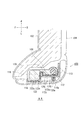
図1は、本発明の第1実施形態に係るサイドエアバッグ装置100を例示した図である。図1(a)ではサイドエアバッグ装置100、およびこのサイドエアバッグ装置100が適用されている車両用シート(シート102)を、右側斜め上方から例示している。
(First Embodiment)
FIG. 1 is a diagram illustrating the
本願では、図1(a)その他のすべての図面において、シート102に正規の位置で着座した乗員から見た前後方向をそれぞれ矢印F(Forward)、B(Back)、その乗員から見た左右をそれぞれ矢印L(Left)、R(Right)、上下方向をそれぞれ矢印U(up)、D(down)で例示する。例えば、本実施形態ではエアバッグクッション(クッション108)を正規着座位置の乗員の左側に膨張展開させているため、クッション108の乗員側とはクッション108の右側のことである。なお、シート102は車両内で向きを変えることも可能であるため、シート102を基準とした前後左右方向は、必ずしも車両を基準とした前後左右方向に一致するとは限らない。
In the present application, in FIG. 1A and all other drawings, the front-back directions as seen from the occupant seated on the
図1(a)では、シート102のシートバック104のうち、表皮やシートパッド(例えばウレタン材)を省略してシートフレーム106のみを例示している。シートフレーム106は、シートバック104に内蔵された骨格となる部材である。
In FIG. 1A, of the seat back 104 of the
サイドエアバッグ装置100は、車両に衝撃が発生した場合などの緊急時に、クッション108を利用してシートに着座した乗員を側方から拘束する。クッション108は、その表面を構成する複数の基布を重ねて縫製や接着することや、OPW(One-Piece Woven)を用いての紡織などによって、袋状に形成されている。そして、クッション108は、巻回や折畳みによって縮小された収納形態となってシート102に搭載される。
The
クッション108は、シートフレーム106のうちシートバック104の側部に沿っているサイドフレーム112に、インフレータ110と共に取り付けられている。クッション108は、インフレータ110からガスを受給し、シート102に着座する乗員(図示省略)の側方に向かって膨張展開する。
The
本実施形態のクッション108は、根本かつ乗員側のプリプッシュチャンバ108aと、乗員とは反対側のメインチャンバ108bとの、大きく2つの部屋に区画されている。プリプッシュチャンバ108aは、インフレータ110からのガスを最初に受給する部位であり、迅速に膨張展開して乗員をシート102の中央側へと押し戻す。メインチャンバ108bは、プリプッシュチャンバ108aが乗員を押すことで確保された空間へと広く膨張展開し、乗員を側方からより十全に拘束する。
The
図1(b)は、図1(a)のクッション108の収納時の様子を例示した図である。図1(b)に例示するように、クッション108は、巻回や折畳み等された収納形態となって、サイドフレーム112の乗員側に保持プレート118(図3(b)参照)およびインフレータ110と共に取り付けられている。
FIG. 1B is a diagram illustrating a state in which the
収納形態のクッション108は、その表面をカバー116が覆っている。カバー116は、本実施形態では熱溶着布で形成されていて、クッション108の収納形態を保持している。カバー116は、縁同士を熱溶着した箇所やスリットやノッチなど、所定の脆弱部(図示省略)を有している。カバー116は、これら脆弱部がクッション108の膨張圧で破断することでクッション108を解放する。
The surface of the
なお、カバー116は、上記熱溶着布のほかにも、クッション108の基布と同じ素材や、不織布などによっても形成可能である。また、カバー116は、クッション108の全体を覆っているが、所定の一部の範囲のみを覆う構成でもクッション108を保持することができる。
In addition to the heat-welded cloth, the
図2は、図1の各状態のクッション108を車両用シート(シート102)の側方から例示した図である。図2(a)は、図1(a)の膨張展開後のクッション108を例示している。図2(a)に例示するように、本実施形態のクッション108は、サイドフレーム112からその前方へと膨張展開する。
FIG. 2 is a view illustrating the
本実施形態では、サイドフレーム112には、クッション108およびインフレータ110と共に、保持プレート118が取り付けられている。保持プレート118は、ある程度の剛性を有した、膨張展開時にクッション108を支える部品である。保持プレートは、サイドフレームの上下方向に沿った長手の形状になっていて、クッション108をシート102の幅方向の外側から支える。
In this embodiment, a holding
図2(b)は、図1(b)の収納形態のクッション108を例示している。収納形態のクッション108は、保持プレート118に沿って縦長の形状になっている。このとき、保持プレート118は、サイドフレーム112の上下方向において収納形態のクッション108よりも大きい寸法を有している(特に延長部分122)。この構成であれば、保持プレート118は、クッション108を膨張展開の当初から効率よく支えることができる。
FIG. 2B illustrates the
図3は、図2(b)のサイドエアバッグ装置100の各状態を示した斜視図である。図3(a)は、図2(b)のサイドエアバッグ装置100をシート102の左後方上側から示している。本実施形態では、サイドフレーム112におけるシート102の幅方向の外側の側面112a(図4参照)に、干渉防止部材130a、130bが設けられている。干渉防止部材130a、130bは、後述するスタッドボルト114a、114b(図3(b)参照)の先端に取り付けられるキャップ状の部品であり、スタッドボルト114a、114bに他の構造物等が接触することを防いでいる。
FIG. 3 is a perspective view showing each state of the
図3(b)は、図3(a)のサイドエアバッグ装置100の分解図である。図3(b)では、表面を覆うカバー116(図3(a)参照)を省略して、保持プレート118やインフレータ110などを例示させている。
FIG. 3B is an exploded view of the
インフレータ110はガス発生装置であって、衝撃発生時に車両側から発信される稼働信号を受けて稼働し、クッション108の内部にガスを供給する。本実施形態で採用しているインフレータ110は、シリンダ型(筒型)の本体部113を有している。本実施形態では、インフレータ110は、クッション108の内部の後方側に、本体部の長手方向を上下方向に向けて内蔵されている。
The
現在普及しているインフレータには、ガス発生剤が充填されていてこれを燃焼させてガスを発生させるタイプや、圧縮ガスが充填されていて熱を発生させることなくガスを供給するタイプ、または燃焼ガスと圧縮ガスとを両方利用するハイブリッドタイプのものなどがある。インフレータ110としては、いずれのタイプのものも利用可能である。
Currently popular inflators are filled with a gas generating agent and burned to generate gas, compressed gas is filled with gas to supply gas without generating heat, or combustion. There is a hybrid type that uses both gas and compressed gas. Any type of
インフレータ110の本体部113のうち、長手方向に離れた2個所にはスタッドボルト114a、114bが設けられている。スタッドボルト114a、114bは、本体部113から延びて、クッション108(図2(a)参照)、保持プレート118、およびサイドフレーム112を貫通し、このサイドフレーム112に締結される。
上述したように、保持プレート118は、ある程度の剛性を有した、膨張展開時にクッション108を支える部品である。例えば、保持プレート118は、材質に樹脂を用いて形成することができる。なお、保持プレート118は、樹脂だけでなく金属を含んで形成することも可能であり、いずれの材質であっても適度な剛性を有した構成を好適に具現化することができる。
As described above, the holding
保持プレート118のうち、基礎部分120は、サイドフレーム112のうち、シートバック104(図3(a)参照)の幅方向の中央側の側面112b(図3(b)中、奥側の面。図4も参照)に沿って平面状に形成されていて、クッション108(図2(a)参照)とサイドフレーム112との間に挟まれるようにして取り付けられる。基礎部分120には、スタッドボルト114a、114bを通すボルト孔121a、121bも形成されている。
Of the holding
延長部分122は、主にメインチャンバ108b(図1(a)参照)を支える部分であり、クッション108のサイドフレーム112の前方にて、基礎部分120からシートバック104(図3(a)参照)の幅方向の外側に延び、そこからさらに前方へと延びた形状になっている。
The
上述したように、干渉防止部材130a、130bは、スタッドボルト114a、114bに他の構造物等が接触することを防ぐ部品である。本実施形態の干渉防止部材130a、130bは、例えば内ネジを有する、丸みをもったキャップ状の部品として実現することができ、スタッドボルト114aの先端に被せるように締結して設置される。干渉防止部材130a、130bは、材質に樹脂を用いて形成することができ、これによってより剛性の低い構成を実現することができる。
As described above, the
図4は、図2(b)の収容状態のクッション108のA−A断面図である。図4に例示するように、保持プレート118、クッション108、およびインフレータ110の本体部113は、サイドフレーム112に対して、シートバック104の幅方向の中央側の側面112bに取り付けられる。そして、スタッドボルト114aは、本体部113からクッション108、保持プレート118、およびサイドフレーム112を貫通して、シートバック104の幅方向の外側の側面112aに突出する。
FIG. 4 is a cross-sectional view taken along the line AA of the
干渉防止部材130aは、スタッドボルト114aの先端に被せられることで、サイドフレーム112から外側にスタッドボルト114aよりも突出した状態となる。上述したように、干渉防止部材130aは、丸みをもった、スタッドボルト114aの先端よりも曲率半径の大きい形状になっている。一例として、干渉防止部材130aは、曲率半径が3.2mm以上となるように形成することができる。この構成によって、干渉防止部材130aは、他の構造物と接触してもこれを損傷するおそれが低減するため、好適である。
By covering the tip of the
上記の干渉防止部材130aによって、万が一、シートバック104の側面に乗員が接触するようなことがあっても、シート102の表皮やシートパッド越しにスタッドボルト114aが乗員に接触することはないため、客室の安全性を高めることができる。また、丸みをもった干渉防止部材130aがスタッドボルト114aに被さっていることで、クッション108の膨張展開時にシートパッド等がスタッドボルト114等に引っ掛かることが無くなり、クッション108はシートパッド等をより円滑に押しのけて膨張展開することが可能になる。
Even if the occupant comes into contact with the side surface of the seat back 104 due to the
保持プレート118の各部位について説明する。側壁領域122aは、延長部分122のうちシート102の前後方向に延びている部分である。側壁領域122aは、シート102の左右方向においてサイドフレーム112から見てインフレータ110とは反対側(乗員とは反対側)に位置していて、膨張展開するクッション108を乗員とは反対側の側方から支え、クッション108の乗員拘束力を高める。
Each part of the holding
後壁領域122bは、延長部分のうち、基礎部分120から側壁領域122の後端へ向かって、シート102の左右方向の外側に延びている部分である。後壁領域122bは、膨張展開時にクッション108を後方から支え、クッション108を迅速かつ円滑に膨張展開させる働きを有している。
The
保持プレート118の延長部分122は、上記の後壁領域122bがサイドフレーム112からスタッドボルト114aよりもシートバック104の幅方向の外側に延びるように設けてもよい。この構成によれば、保持プレート118の延長部分122も利用して、スタッドボルト114aに他の構造物が干渉することを防ぐことが可能になる。
The
保持プレート118は、基礎部分120から後壁領域122bにかけて、サイドフレーム112に噛み合うよう形成されている。例えば、サイドフレーム112の前縁126は、インフレータ110側(本実施形態では乗員側)に屈曲している。保持プレート118の基礎部分120の前端部128は、前縁126の後側に沿っていったん乗員側へと屈曲し、この前縁126を乗り越えるようにさらに屈曲して後壁領域122bとつながっている。そのため、基礎部分120から後壁領域122bにかけて、サイドフレーム112の前縁126に沿った凹形状の領域が形成されている。
The holding
図5は、図4のクッション108の膨張展開する過程を例示した図である。図5(a)は、図4の収納形態のクッション108を例示している。図5(a)の状態において、車両に衝撃が発生すると、所定のセンサがそれを検知してインフレータ110に稼働信号を送り、インフレータ110が稼働してガスがクッションに供給される。
FIG. 5 is a diagram illustrating a process of expansion and expansion of the
図5(b)は、図5(a)のインフレータ110が稼働した直後の様子を例示している。図5(b)に例示するように、インフレータ110からガスが供給されると、クッション108はまずプリプッシュチャンバ108aから膨張を開始する。このときの膨張の圧力によって、カバー116はスリットやノッチ等の所定の脆弱部(図示省略)で破断し、クッション108はカバー116から解放される。そして、メインチャンバ108bも、プリプッシュチャンバ108aからガスを受給して膨張展開する。
FIG. 5B illustrates a state immediately after the
後壁領域122bは、膨張展開するメインチャンバ108bの後方に面接触し、メインチャンバ108bを後方から支える。側壁領域122aは、膨張展開するメインチャンバ108bの乗員とは反対側の側方に前後方向わたって面接触し、メインチャンバ108bを側方から支える。メインチャンバ108bは、これら後壁領域122bおよび側壁領域122aから反力を得ることで、シート102の前方へと迅速かつ円滑に膨張展開することが可能になっている。
The
図5(c)は、図5(b)のクッション108がさらに膨張展開した様子を例示している。膨張展開したクッション108には、乗員が側方から接触する。このとき、メインチャンバ108bの乗員とは反対側の側方には、保持プレート118の側壁領域122aが存在している。そのため、メインチャンバ108bは、側壁領域122aから反力を得て、乗員からの荷重を好適に吸収し、乗員をより十全に拘束することが可能になっている。
FIG. 5 (c) illustrates how the
以上のように、本実施形態によれば、まず、クッション108は、サイドフレーム112のうち、シートバック104の幅方向の中央側の側面112bに取り付けられているため、乗員を拘束するときにサイドフレーム112から反力を得ることが可能になっている。さらに、保持プレート118の特に側壁領域122aによってクッション108のメインチャンバ108bを側方から支えることで、メインチャンバ108bの乗員拘束力をより効率よく向上させることが可能になっている。また、クッションの膨張展開の途中においても、前方へ膨張展開しようとするメインチャンバ108bを後壁領域122bによって後ろから支え、クッション108の円滑な膨張展開、ひいてはクッション108の乗員保護性能の向上を図ることが可能になっている。
As described above, according to the present embodiment, first, since the
前述したように、保持プレート118は、基礎部分120と後壁領域122aとの間の凹形状の領域によって、サイドフレーム112の前縁126に噛み合った状態となっている。この構成によって、保持プレート118は、サイドフレーム112に対する位置ずれを防ぎ、クッション108の膨張展開途中において姿勢を好適に保持することが可能になっている。この作用によっても、側壁領域122aや後壁領域122bは、メインチャンバ108bをより効率よく支えることが可能になる。
As described above, the holding
図5(b)において、保持プレート118をシート102の上方から見て、後壁領域122bと基礎部分120とがサイドフレーム112を挟んで成す角度α1は、90°以上であると好適である。この構成の後壁領域122bであれば、メインチャンバ108bに対して、シート102の前方に向かう角度か、もしくは前方のやや乗員寄りに向かう角度で反力を加えることができる。したがって、メインチャンバ108bを円滑に膨張展開させ、その乗員保護性能の向上を図ることが可能になる。
In FIG. 5B, when the holding
以上説明したように、本実施形態のサイドエアバッグ装置100であれば、主に保持プレート118と干渉防止部材130a、130bとを利用して、クッション108の乗員保護性能や乗員拘束力を向上し、さらに客室の安全にも配慮することが可能となっている。
As described above, in the
(第2実施形態)
図6は、本発明の第2実施形態に係るサイドエアバッグ装置200を例示した図である。図6(a)は、図3(a)に対応してサイドエアバッグ装置200を例示している。当該サイドエアバッグ装置200は、干渉防止部材202(図6(b)参照)の構成において、第1実施形態のサイドエアバッグ装置100の構成と異なっている。以降の記載において、既に説明した構成要素については、同じ符号を付することによって、その説明を省略する。また、既に説明した構成要素と同じ名称の構成要素は、異なる符号が付されていても、同じ構成および機能を有するものとする。
(Second Embodiment)
FIG. 6 is a diagram illustrating the
干渉防止部材202(図6(b)参照)は、サイドフレーム112の上下方向に沿って、複数の突起202aが形成された構成になっている。各突起202aは、保持プレート118から突出してサイドフレーム112を貫通し、サイドフレーム112から外側にスタッドボルト114a、114bよりも突出している。
The interference prevention member 202 (see FIG. 6B) has a configuration in which a plurality of
図6(b)は、図6(a)のサイドエアバッグ装置200の分解図である。図6(b)に例示するように、干渉防止部材202は、保持プレート118の基礎部分120のうち、ボルト孔121a、121bの後方側にて、接着や固定具等を使用して取り付けられている。干渉防止部材202の突起202aは、ボルト孔121aとボルト孔121bとを結ぶ範囲よりも長い範囲にわたるようにして、計5つ形成されている。干渉防止部材202のうち、突起202aは主に樹脂製で剛性を抑えた構成となっているが、突起202a以外の基部202bなどには金属も使用することができる。
FIG. 6B is an exploded view of the
図7は、図6(a)のサイドエアバッグ装置200のB−B断面図である。図7に例示するように、干渉防止部材202(図6(b)参照)はサイドフレーム112のうちスタッドボルト114aよりも後方に設けられている。そして、突起202aは、スタッドボルト114aの後方の近傍からサイドフレーム112を貫通して突出した状態となっている。
FIG. 7 is a sectional view taken along line BB of the
突起202aは、サイドフレーム112からシートバック104(図4参照)の幅方向の外側へ、スタッドボルト114aよりも突出するように延びている。突起202aの先端は、スタッドボルト114aの先端よりも曲率半径の大きい形状となっていて、例えば曲率半径が3.2mm以上に設定されている。他にも、突起202aの先端には、部分的に平坦な領域を形成することも可能である。
The
干渉防止部材202(図6(b)参照)に加えて、保持プレート118の延長部分122、特に後壁領域122bは、サイドフレーム112からスタッドボルト114aよりも外側に延びるように設けられている。本実施形態では、後壁領域122bと突起202aとが、共にスタッドボルト114aの前後においてスタッドボルト114aよりも外側へ突出した構成となるため、他の構造物等のスタッドボルト114aの先端への接触を効率よく防ぐことが可能になっている。
In addition to the interference prevention member 202 (see FIG. 6B), the
以上、本実施形態のサイドエアバッグ装置200によっても、保持プレート118によってクッション108の乗員保護性能や乗員拘束力を向上したうえで、干渉防止部材202によってスタッドボルト114aの先端に乗員や他の構造物が接触することがないようにし、客室の安全性を高めることができる。
As described above, also in the
以上、添付図面を参照しながら本発明の好適な実施例について説明したが、以上に述べた実施形態は、本発明の好ましい例であって、これ以外の実施態様も、各種の方法で実施または遂行できる。特に本願明細書中に限定される主旨の記載がない限り、この発明は、添付図面に示した詳細な部品の形状、大きさ、および構成配置等に制約されるものではない。また、本願明細書の中に用いられた表現および用語は、説明を目的としたもので、特に限定される主旨の記載がない限り、それに限定されるものではない。 Although preferred embodiments of the present invention have been described above with reference to the accompanying drawings, the embodiments described above are preferred examples of the present invention, and other embodiments may also be implemented by various methods. Can be carried out. Unless otherwise specified in the specification of the present application, the present invention is not limited to the shape, size, configuration arrangement, etc. of the detailed parts shown in the accompanying drawings. In addition, the expressions and terms used in the specification of the present application are for the purpose of explanation, and are not limited thereto unless otherwise specified.
したがって、当業者であれば、特許請求の範囲に記載された範疇内において、各種の変更例または修正例に想到し得ることは明らかであり、それらについても当然に本発明の技術的範囲に属するものと了解される。 Therefore, it is clear that a person skilled in the art can come up with various modifications or modifications within the scope of the claims, which naturally belong to the technical scope of the present invention. It is understood as a thing.
本発明は、車両用シートに設けられるサイドエアバッグ装置に利用することができる。 The present invention can be used for a side airbag device provided on a vehicle seat.
100…第1実施形態のサイドエアバッグ装置、102…シート、104…シートバック、106…シートフレーム、108…クッション、108a…プリプッシュチャンバ、108b…メインチャンバ、110…インフレータ、112…サイドフレーム、113…インフレータの本体部、114a…上側のスタッドボルト、114b…下側のスタッドボルト、116…カバー、118…保持プレート、120…保持プレートの基礎部分、121a…上側のボルト孔、121b…下側のボルト孔、122…保持プレートの延長部分、122a…側壁領域、122b…後壁領域、126…サイドフレームの前縁、128…基礎部分の前端部、130a…上側の干渉防止部材、130b…下側の干渉防止部材、200…第2実施形態のサイドエアバッグ装置、202…第2実施形態の干渉防止部材、202a…干渉防止部材の突起、202b…干渉防止部材の基部 100 ... Side airbag device of the first embodiment, 102 ... Seat, 104 ... Seat back, 106 ... Seat frame, 108 ... Cushion, 108a ... Pre-push chamber, 108b ... Main chamber, 110 ... Inflator, 112 ... Side frame, 113 ... Inflator body, 114a ... Upper stud bolt, 114b ... Lower stud bolt, 116 ... Cover, 118 ... Holding plate, 120 ... Holding plate base, 121a ... Upper bolt hole, 121b ... Lower Bolt holes, 122 ... extension of the holding plate, 122a ... side wall area, 122b ... rear wall area, 126 ... front edge of side frame, 128 ... front end of foundation, 130a ... upper interference prevention member, 130b ... lower Side interference prevention member, 200 ... Side airbag device of the second embodiment, 202 ... Interference prevention member of the second embodiment, 202a ... Protrusion of interference prevention member, 202b ... Base of interference prevention member
Claims (7)
袋状であって巻回または折り畳まれた収納形態となっているエアバッグクッションと、
前記車両用シートのシートバックの側部に内蔵されているサイドフレームに前記エアバッグクッションと共に取り付けられるインフレータと、
を備え、
前記インフレータは、
前記サイドフレームのうち前記シートバックの幅方向の中央側に設置される本体部と、
前記本体部から前記サイドフレームを貫通して前記幅方向の外側に突出するスタッドボルトと、
を有し、
当該サイドエアバッグ装置はさらに、
前記サイドフレームから前記外側に前記スタッドボルトよりも突出していて、該スタッドボルトの先端よりも曲率半径の大きい1つ以上の干渉防止部材と、
前記エアバッグクッションおよび前記インフレータと共に前記サイドフレームに取り付けられる所定の保持プレートと、
を備え、
前記保持プレートは、
前記エアバッグクッションと前記サイドフレームとの間に形成されている基礎部分と、
前記サイドフレームの前方にて前記基礎部分から前記外側へ延びさらに前方へ延びている延長部分と、
を含み、
前記干渉防止部材は、前記サイドフレームのうち前記スタッドボルトよりも後方に設けられていることを特徴とするサイドエアバッグ装置。 A side airbag device that restrains an occupant seated on a vehicle seat from the side.
An airbag cushion that is bag-shaped and has a rolled or folded storage form.
An inflator attached together with the airbag cushion to a side frame built in the side of the seat back of the vehicle seat,
With
The inflator
The main body of the side frame installed on the center side of the seat back in the width direction,
A stud bolt that penetrates the side frame from the main body and projects outward in the width direction,
Have,
The side airbag device also
One or more anti-interference members projecting from the side frame to the outside of the stud bolt and having a radius of curvature larger than the tip of the stud bolt .
With a predetermined holding plate attached to the side frame together with the airbag cushion and the inflator,
With
The holding plate
A foundation portion formed between the airbag cushion and the side frame,
An extension portion extending outward from the foundation portion in front of the side frame and further extending forward.
Including
The interference prevention member, the side air bag device characterized that you have provided to the rear than the stud bolt of the side frame.
Priority Applications (2)
| Application Number | Priority Date | Filing Date | Title |
|---|---|---|---|
| JP2018019423A JP6810072B2 (en) | 2018-02-06 | 2018-02-06 | Side airbag device |
| EP19154753.8A EP3521109B1 (en) | 2018-02-06 | 2019-01-31 | Side airbag apparatus |
Applications Claiming Priority (1)
| Application Number | Priority Date | Filing Date | Title |
|---|---|---|---|
| JP2018019423A JP6810072B2 (en) | 2018-02-06 | 2018-02-06 | Side airbag device |
Publications (2)
| Publication Number | Publication Date |
|---|---|
| JP2019137100A JP2019137100A (en) | 2019-08-22 |
| JP6810072B2 true JP6810072B2 (en) | 2021-01-06 |
Family
ID=65275991
Family Applications (1)
| Application Number | Title | Priority Date | Filing Date |
|---|---|---|---|
| JP2018019423A Active JP6810072B2 (en) | 2018-02-06 | 2018-02-06 | Side airbag device |
Country Status (2)
| Country | Link |
|---|---|
| EP (1) | EP3521109B1 (en) |
| JP (1) | JP6810072B2 (en) |
Families Citing this family (6)
| Publication number | Priority date | Publication date | Assignee | Title |
|---|---|---|---|---|
| US11020922B2 (en) * | 2018-07-27 | 2021-06-01 | Adidas Ag | Footwear with padding and midsole structures and the method of making the same |
| US20200189513A1 (en) * | 2018-12-14 | 2020-06-18 | Key Safety Systems, Inc. | Far side crash mitigation |
| EP4218495A1 (en) * | 2019-04-17 | 2023-08-02 | Autoliv Development AB | Side airbag device |
| CN112009418B (en) * | 2019-05-30 | 2023-01-24 | 奥托立夫开发公司 | Side airbag device |
| US11958429B2 (en) | 2020-04-09 | 2024-04-16 | Autoliv Development Ab | Side airbag device |
| US20230406254A1 (en) * | 2020-10-13 | 2023-12-21 | Autoliv Development Ab | Side airbag device |
Family Cites Families (12)
| Publication number | Priority date | Publication date | Assignee | Title |
|---|---|---|---|---|
| JPS6275732U (en) * | 1985-10-31 | 1987-05-15 | ||
| US6352304B1 (en) * | 1999-08-19 | 2002-03-05 | Johnson Controls Technology Company | Device for indicating an airbag module position |
| JP3867537B2 (en) * | 2001-09-28 | 2007-01-10 | 豊田合成株式会社 | Airbag device |
| JP4691727B2 (en) * | 2006-03-29 | 2011-06-01 | ダイハツ工業株式会社 | Seat with built-in side airbag |
| US7669888B2 (en) * | 2007-07-19 | 2010-03-02 | Toyoda Gosei Co., Ltd. | Side airbag apparatus |
| JP4952422B2 (en) * | 2007-07-19 | 2012-06-13 | 豊田合成株式会社 | Side airbag device |
| JP5271722B2 (en) * | 2009-01-13 | 2013-08-21 | 本田技研工業株式会社 | Arrangement structure of airbag device |
| JP2012140044A (en) * | 2010-12-28 | 2012-07-26 | Toyota Motor Corp | Vehicular seat |
| JP6582897B2 (en) * | 2015-11-09 | 2019-10-02 | テイ・エス テック株式会社 | Vehicle seat |
| JP6428666B2 (en) * | 2016-02-10 | 2018-11-28 | トヨタ自動車株式会社 | Vehicle seat with side airbag device |
| JP6394657B2 (en) * | 2016-07-22 | 2018-09-26 | トヨタ自動車株式会社 | Vehicle occupant restraint system |
| DE202016005581U1 (en) * | 2016-09-12 | 2017-12-13 | GM Global Technology Operations LLC (n. d. Ges. d. Staates Delaware) | Backrest for a vehicle seat and vehicle seat with the backrest |
-
2018
- 2018-02-06 JP JP2018019423A patent/JP6810072B2/en active Active
-
2019
- 2019-01-31 EP EP19154753.8A patent/EP3521109B1/en active Active
Also Published As
| Publication number | Publication date |
|---|---|
| EP3521109B1 (en) | 2020-09-30 |
| JP2019137100A (en) | 2019-08-22 |
| EP3521109A1 (en) | 2019-08-07 |
Similar Documents
| Publication | Publication Date | Title |
|---|---|---|
| JP6810072B2 (en) | Side airbag device | |
| JP6810281B2 (en) | Side airbag device | |
| JP5595154B2 (en) | Curtain airbag | |
| KR102362071B1 (en) | Side airbag device | |
| US11833990B2 (en) | Side airbag device, vehicle seat provided with same, and method for manufacturing side airbag device | |
| JP2018052275A (en) | Airbag device for vehicle and wrapping material used therefor | |
| JP2018024285A (en) | Air bag device | |
| JPWO2018211894A1 (en) | Side airbag device | |
| JP2020050239A (en) | Side airbag device and wrapping material | |
| JP6185653B2 (en) | Curtain airbag device | |
| KR102408015B1 (en) | Side airbag device | |
| JP7175387B2 (en) | side airbag device | |
| JP5972856B2 (en) | Curtain airbag device | |
| JP5990156B2 (en) | Curtain airbag device | |
| JP6841797B2 (en) | Airbag device | |
| JP7312908B2 (en) | side airbag device | |
| JP6009655B2 (en) | Airbag device | |
| JP5948296B2 (en) | Curtain airbag device | |
| JP2017140953A (en) | Airbag device | |
| JP6096651B2 (en) | Curtain airbag device and vehicle mounting structure for curtain airbag device | |
| JP6267664B2 (en) | Side airbag device |
Legal Events
| Date | Code | Title | Description |
|---|---|---|---|
| RD03 | Notification of appointment of power of attorney |
Free format text: JAPANESE INTERMEDIATE CODE: A7423 Effective date: 20180711 |
|
| A521 | Request for written amendment filed |
Free format text: JAPANESE INTERMEDIATE CODE: A523 Effective date: 20181126 |
|
| A621 | Written request for application examination |
Free format text: JAPANESE INTERMEDIATE CODE: A621 Effective date: 20190917 |
|
| A977 | Report on retrieval |
Free format text: JAPANESE INTERMEDIATE CODE: A971007 Effective date: 20200804 |
|
| A131 | Notification of reasons for refusal |
Free format text: JAPANESE INTERMEDIATE CODE: A131 Effective date: 20200908 |
|
| A521 | Request for written amendment filed |
Free format text: JAPANESE INTERMEDIATE CODE: A523 Effective date: 20201016 |
|
| TRDD | Decision of grant or rejection written | ||
| A01 | Written decision to grant a patent or to grant a registration (utility model) |
Free format text: JAPANESE INTERMEDIATE CODE: A01 Effective date: 20201201 |
|
| A61 | First payment of annual fees (during grant procedure) |
Free format text: JAPANESE INTERMEDIATE CODE: A61 Effective date: 20201210 |
|
| R150 | Certificate of patent or registration of utility model |
Ref document number: 6810072 Country of ref document: JP Free format text: JAPANESE INTERMEDIATE CODE: R150 |
|
| R250 | Receipt of annual fees |
Free format text: JAPANESE INTERMEDIATE CODE: R250 |