JP2012140044A - Vehicular seat - Google Patents
Vehicular seat Download PDFInfo
- Publication number
- JP2012140044A JP2012140044A JP2010292207A JP2010292207A JP2012140044A JP 2012140044 A JP2012140044 A JP 2012140044A JP 2010292207 A JP2010292207 A JP 2010292207A JP 2010292207 A JP2010292207 A JP 2010292207A JP 2012140044 A JP2012140044 A JP 2012140044A
- Authority
- JP
- Japan
- Prior art keywords
- vehicle
- seat back
- seat
- disposed
- dilatant
- Prior art date
- Legal status (The legal status is an assumption and is not a legal conclusion. Google has not performed a legal analysis and makes no representation as to the accuracy of the status listed.)
- Pending
Links
Images


Abstract
Description
本発明は、車両用シートに係り、特にサイドエアバッグ装置を搭載した車両用シートに関する。 The present invention relates to a vehicle seat, and particularly to a vehicle seat equipped with a side airbag device.
下記特許文献1に示された車両側部のエネルギ吸収構造では、シートバックのサイド部には、表皮材(シート表皮)によって被覆されたパッド(シートバックパッド)が配設されている。このシートバックパッドは、パッド本体とインサート部材とからなり、両者の間には破断用境界部が設定されている。この破断用境界部は、サイド部に内設されたエアバッグユニットの前方側に配置されており、エアバッグが膨張した際には、シートバックパッドが破断用境界部において拡開破断すると共に、シート表皮の縫目(縫製部)が開裂し、エアバッグがサイド部の前方側へ展開する。 In the vehicle side energy absorbing structure disclosed in Patent Document 1 below, a pad (seat back pad) covered with a skin material (seat skin) is disposed on the side part of the seat back. This seat back pad is composed of a pad main body and an insert member, and a breaking boundary is set between the two. This breaking boundary part is disposed on the front side of the airbag unit provided in the side part, and when the airbag is inflated, the seat back pad is expanded and broken at the breaking boundary part, The seam (sewing part) of the seat cover is cleaved, and the airbag is deployed to the front side of the side part.
上述のエネルギ吸収構造では、インサート部材の硬度がパッド本体の硬度よりも高く設定されている。このため、インサート部材がパッド本体と同化し難くなっており、シートバックパッドが破断用境界部において容易に拡開破断するようになっている。これにより、エアバッグの展開安定性を向上させるようにしている。 In the energy absorbing structure described above, the hardness of the insert member is set higher than the hardness of the pad body. For this reason, it is difficult for the insert member to be assimilated with the pad main body, and the seat back pad is easily expanded and broken at the breaking boundary. Thereby, the deployment stability of the airbag is improved.
しかしながら、上述のエネルギ吸収構造では、エアバッグの膨張圧によってシートバックパッドが潰れること、及びシートバックパッドとシート表皮がシートバックの上下方向から見て円形断面形状に変形すること等により、適正時間内ではあるがシート表皮の縫製部の開裂が遅れることが考えられる。このため、サイドエアバッグの展開を早期化する点で改善の余地がある。 However, in the above energy absorbing structure, the seat back pad is crushed by the inflation pressure of the airbag, and the seat back pad and the seat skin are deformed into a circular cross-sectional shape when viewed from the vertical direction of the seat back. Although it is within, it is considered that the tearing of the sewn part of the sheet skin is delayed. For this reason, there is room for improvement in terms of accelerating the deployment of the side airbag.
本発明は上記事実を考慮し、サイドエアバッグを早期に展開させることができる車両用シートを得ることが目的である。 In view of the above facts, the present invention has an object to obtain a vehicle seat in which a side airbag can be deployed at an early stage.
請求項1に記載の発明に係る車両用シートは、シートバックのクッション材を構成すると共に、前記シートバックにおける車両幅方向外側のサイド部内に空洞部を形成したシートバックパッドと、前記シートバックパッドを被覆すると共に、前記サイド部の前端側に配置された部位に縫製部が設けられたシート表皮と、前記空洞部内に配設され、インフレータから発生したガスによって膨張すると共に、前記サイド部の前部側において前記シートバックパッドを車両幅方向外側の外側展開部と当該外側展開部よりも車両幅方向内側の内側展開部とに展開させつつ前記縫製部を開裂させて車両前方側へ展開するサイドエアバッグと、を備え、前記外側展開部及び前記内側展開部の少なくとも一部がダイラタント特性を有する材料からなるダイラタント部材によって構成されている。 A vehicle seat according to the invention of claim 1 constitutes a cushion material for a seat back, and a seat back pad in which a hollow portion is formed in a side portion of the seat back in the vehicle width direction, and the seat back pad And a seat skin provided with a sewing portion at a portion arranged on the front end side of the side portion, and disposed in the cavity portion and inflated by gas generated from the inflator, and in front of the side portion. The side where the seat back pad is developed on the outer side of the vehicle width direction on the outer side and the inner side of the inner side of the vehicle side of the outer side of the outer side, and the sewing part is opened to the front side of the vehicle. An air bag, and at least a part of the outer deployment portion and the inner deployment portion is made of a material having a dilatant characteristic. It is constituted by a cement member.
請求項1に記載の車両用シートでは、シートバックの車両幅方向外側のサイド部内には、シートバックパッドによって形成された空洞部が設けられている。この空洞部内に配設されたインフレータが作動すると、当該空洞部内に配設されたサイドエアバッグが膨張し、シートバックパッドにサイドエアバッグの膨張圧が加えられる。これにより、シートバックパッドがサイド部の前部側において外側展開部と内側展開部とに展開(拡開)すると共にシート表皮の縫製部が開裂し、サイドエアバッグが車両前方側へ展開する。 In the vehicle seat according to the first aspect, a hollow portion formed by the seat back pad is provided in the side portion of the seat back on the outer side in the vehicle width direction. When the inflator disposed in the cavity is activated, the side airbag disposed in the cavity is inflated, and the inflation pressure of the side airbag is applied to the seat back pad. As a result, the seat back pad expands (expands) into the outer deployed portion and the inner deployed portion on the front side of the side portion, and the sewn portion of the seat cover is cleaved, and the side airbag is deployed toward the front side of the vehicle.
ここで、上述のシートバックパッドは、外側展開部及び内側展開部の少なくとも一部がダイラタント特性を有する材料からなるダイラタント部材によって構成されている。このため、上述の如くサイドエアバッグが膨張する際には、サイドエアバッグからの衝撃力によってダイラタント部材が瞬時に硬化する。これにより、上記少なくとも一部及びこれを被覆するシート表皮の変形が抑制されるので、当該変形によってシート表皮の縫製部へのバッグ膨張圧の伝達が遅れることを回避できる。その結果、シート表皮の縫製部を早期に開裂させてシートバックパッドを早期に拡開させることが可能になるので、サイドエアバッグを早期に展開させることが可能になる。なお、請求項1に記載の空洞部には、開断面形状のものが含まれる。 Here, the above-described seat back pad is constituted by a dilatant member in which at least a part of the outer spread portion and the inner spread portion is made of a material having dilatant characteristics. For this reason, when the side airbag is inflated as described above, the dilatant member is instantly cured by the impact force from the side airbag. Thereby, since the deformation | transformation of the said seat skin which covers at least one part and this is suppressed, it can avoid delaying the transmission of the bag expansion pressure to the sewing part of a seat skin by the said deformation | transformation. As a result, the sewn portion of the seat cover can be cleaved at an early stage and the seat back pad can be expanded at an early stage, so that the side airbag can be deployed at an early stage. In addition, the thing of an open cross-section is contained in the cavity part of Claim 1.
請求項2に記載の発明に係る車両用シートは、請求項1に記載の車両用シートにおいて、前記インフレータは、前記サイドエアバッグ内の後端部に配設され、ダイラタント部材の後端は、前記シートバックの上下方向から見た前記インフレータの中心よりも車両後方側に配置されている。 A vehicle seat according to a second aspect of the present invention is the vehicle seat according to the first aspect, wherein the inflator is disposed at a rear end portion in the side airbag, and a rear end of the dilatant member is It is arranged on the vehicle rear side with respect to the center of the inflator viewed from the vertical direction of the seat back.
請求項2に記載の車両用シートでは、インフレータがサイドエアバッグ内の後端部に配設されている。このため、サイドエアバッグは、インフレータよりも車両前方側へ膨張するが、ダイラタント部材の後端は、シートバックの上下方向から見たインフレータの中心よりも車両後方側に配置されている。これにより、サイドエアバッグがダイラタント部材の後端とインフレータとの間へ膨張する(入り込む)ことを防止できる。 In the vehicle seat according to the second aspect, the inflator is disposed at the rear end portion in the side airbag. For this reason, the side airbag is inflated to the front side of the vehicle relative to the inflator, but the rear end of the dilatant member is disposed on the rear side of the vehicle relative to the center of the inflator as viewed from the vertical direction of the seat back. Thereby, it is possible to prevent the side airbag from inflating (entering) between the rear end of the dilatant member and the inflator.
請求項3に記載の発明に係る車両用シートは、請求項1又は請求項2に記載の車両用シートにおいて、一端側が前記縫製部に縫合されると共に他端側が前記シートバックのフレームに係止され、前記サイドエアバッグの膨張圧を受けて伸張することにより前記膨張圧を前記縫製部に伝達する力布を備え、前記ダイラタント部材は、前記サイドエアバッグと前記力布との間に配置されている。 A vehicle seat according to a third aspect of the present invention is the vehicle seat according to the first or second aspect, wherein one end side is sewn to the sewing portion and the other end side is locked to the frame of the seat back. And a force cloth for transmitting the expansion pressure to the sewing portion by receiving and expanding the expansion pressure of the side airbag, and the dilatant member is disposed between the side airbag and the force cloth. ing.
請求項3に記載の車両用シートでは、一端側がシート表皮の縫製部に縫合され、他端側がシートバックフレームに係止された力布が、サイドエアバッグの膨張圧を受けて伸張することにより、縫製部にバッグ膨張圧が伝達される。しかも、ダイラタント部材は、サイドエアバッグと力布との間に配置されている。このため、サイドエアバッグが膨張する際には、サイドエアバッグからの衝撃力によってダイラタント部材が瞬時に硬化することにより、力布を迅速に伸張させることができる。つまり、ダイラタント部材の代わりに通常のパッド材が配設されている場合には、パッド材の変形により力布の伸張が遅れることになるが、本発明では力布の迅速な伸張によって縫製部に早期にバッグ膨張圧を伝達することができる。これにより、縫製部の開裂を一層早めることができる。 In the vehicular seat according to claim 3, the force cloth having one end side sewn to the sewing portion of the seat cover and the other end side locked to the seat back frame is expanded by receiving the inflation pressure of the side airbag. The bag inflation pressure is transmitted to the sewing portion. And the dilatant member is arrange | positioned between the side airbag and the power cloth. For this reason, when the side airbag is inflated, the dilatant member is instantly cured by the impact force from the side airbag, so that the webbing can be quickly expanded. In other words, when a normal pad material is provided instead of the dilatant member, the extension of the baffle is delayed due to the deformation of the pad material. Bag inflation pressure can be transmitted at an early stage. Thereby, the tearing of the sewing portion can be further accelerated.
請求項4に記載の発明に係る車両用シートは、請求項1又は請求項2に記載の車両用シートにおいて、一端側が前記縫製部に縫合されると共に他端側が前記シートバックのフレームに係止され、前記サイドエアバッグの膨張圧を受けて伸張することにより前記膨張圧を前記縫製部に伝達する力布を備え、前記ダイラタント部材は、前記シート表皮と前記力布との間に配置されている。 A vehicle seat according to a fourth aspect of the present invention is the vehicle seat according to the first or second aspect, wherein one end side is sewn to the sewing portion and the other end side is locked to the frame of the seat back. And a force cloth that transmits the expansion pressure to the sewing part by receiving and expanding the expansion pressure of the side airbag, and the dilatant member is disposed between the seat skin and the force cloth. Yes.
請求項4に記載の車両用シートでは、一端側がシート表皮の縫製部に縫合され、他端側がシートバックフレームに係止された力布が、サイドエアバッグの膨張圧を受けて伸張することにより、縫製部にバッグ膨張圧が伝達される。しかも、ダイラタント部材は、シート表皮と力布との間に配置されている。このため、サイドエアバッグが膨張する際には、サイドエアバッグからの衝撃力が力布を介してダイラタント部材に加えられることにより、ダイラタント部材が瞬時に硬化し、力布及びシート表皮の変形が抑制される。これにより、シート表皮の縫製部に早期にバッグ膨張圧を伝達することができるので、縫製部の開裂を一層早めることができる。 In the vehicular seat according to claim 4, the force cloth whose one end is sewn to the sewing portion of the seat cover and the other end is locked to the seat back frame is stretched by receiving the inflation pressure of the side airbag. The bag inflation pressure is transmitted to the sewing portion. And the dilatant member is arrange | positioned between the sheet | seat skin and the power cloth. For this reason, when the side airbag is inflated, the impact force from the side airbag is applied to the dilatant member via the baffle, so that the dilatant member is instantly cured, and the deformation of the baffle and the seat skin is changed. It is suppressed. Thereby, since bag expansion pressure can be transmitted to the sewing part of a sheet | seat skin at an early stage, the tearing of the sewing part can be further accelerated.
請求項5に記載の発明に係る車両用シートは、請求項1〜請求項4の何れか1項に記載の車両用シートにおいて、前記ダイラタント部材は、前記外側展開部の少なくとも一部を構成すると共に、前記シートバックのフレームに対して車両幅方向外側にオーバーラップして配置された侵入抑制部を有する。 The vehicle seat according to a fifth aspect of the present invention is the vehicle seat according to any one of the first to fourth aspects, wherein the dilatant member constitutes at least a part of the outer deployment portion. In addition, there is an intrusion suppression portion that is arranged so as to overlap the outer side in the vehicle width direction with respect to the frame of the seat back.
請求項5に記載の車両用シートでは、車両の側面衝突時に車体側部(サイドドアなど)がシートバックのサイド部に衝突すると、その衝撃力によって、外側展開部の少なくとも一部を構成するダイラタント部材が瞬時に硬化する。このダイラタント部材は、シートバックのフレームに対して車両幅方向外側にオーバーラップして配置された侵入抑制部を有している。このため、シートバックのフレームと車体側部との間に、硬化した侵入抑制部が介在することにより、車両幅方向内側(乗員側)への車体側部の侵入が抑制される。これにより、サイドエアバッグの展開スペースを十分に確保することができる。 In the vehicle seat according to claim 5, when a vehicle body side part (such as a side door) collides with a side part of the seat back at the time of a side collision of the vehicle, a dilatant that forms at least a part of the outer deployment part by the impact force. The member hardens instantly. The dilatant member has an intrusion suppressing portion that is disposed so as to overlap the outer side of the seat back frame in the vehicle width direction. For this reason, since the hardened intrusion suppression portion is interposed between the seat back frame and the vehicle body side portion, the vehicle body side portion is prevented from entering the vehicle width direction inner side (occupant side). Thereby, the deployment space of the side airbag can be sufficiently secured.
以上説明したように、本発明に係る車両用シートでは、サイドエアバッグを早期に展開させることができる。 As described above, in the vehicle seat according to the present invention, the side airbag can be deployed early.
<第1の実施形態>
以下、図1〜図3を用いて、本発明の第1実施形態に係る車両用シート10について説明する。なお、各図中に適宜示される矢印FRは車両前方側を示し、矢印UPは車両上方側を示し、矢印INは車両幅方向内側を示している。また、本第1実施形態では、車両用シート10の前方向、上方向、幅方向は、車両の前方向、上方向、幅方向と一致している。
<First Embodiment>
Hereinafter, the
本第1実施形態に係る車両用シート10は、自動車のフロントシートであり、図1に示されるように、乗員が着座するシートクッション12と、このシートクッション12の後端部に傾倒可能に支持されて乗員の背もたれとして利用されるシートバック14と、を含んで構成されている。
A
シートバック14は、シート幅方向中央部に配置され、乗員の背中を直接支持するシートバック本体部14Aと、このシートバック本体部14Aの車幅方向外側の端部に一体的に設けられたドア側サイド部14B(車両幅方向外側のサイド部)と、シートバック本体部14Aの車幅方向内側の端部に一体的に設けられたトンネル側サイド部14Cとを備えている。なお、ドア側サイド部14B及びトンネル側サイド部14Cは、何れも車両前方側へ隆起した形状になっており、所謂サイドサポートとして機能する。
The seat back 14 is disposed at the center portion in the seat width direction, and a seat back
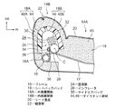
図2に示されるように、ドア側サイド部14Bの略中央には、パイプ材によって形成されてシートバック14のフレーム16(以下、シートバックフレーム16という)を構成するフレームサイド部16Aがシートバック14の上下方向に沿って配設されている。なお、シートバックフレーム16は、シートバック14の前方側から見て下方が開放された略逆U字状に構成されており、その内の両サイドにフレームサイド部16Aが配置されている。これらのフレームサイド部16Aの間には、複数のワイヤフレーム17が掛け渡されている。
As shown in FIG. 2, a
上述のシートバックフレーム16には、シートバックパッド18が取り付けられている。このシートバックパッド18は、シートバック14のクッション材を構成しており、シート表皮20によって被覆されている。このシート表皮20には、ドア側サイド部14Bの前端部に配置された部位に、車両上下方向に延びる縫製部22が設けられている。また、シートバックパッド18は、ドア側サイド部14B内に空洞部24を形成しており、当該空洞部24内には、サイドエアバッグ装置を構成するサイドエアバッグモジュール26が配設されている。
A seat back
サイドエアバッグモジュール26は、ガス発生手段としてのインフレータ28、及びインフレータ28から噴出されたガスによって車両前方側へ膨張展開するサイドエアバッグ30を備えている。サイドエアバッグ30は、布や樹脂シート等のシート状の材料によって袋状に縫製されたものであり、折り畳まれた状態で空洞部24内に配設されている。このサイドエアバッグ30は、容易に破断するラップ材32によって包まれることにより折り畳まれた状態に保持されている。
The
一方、インフレータ28は、円柱状に形成されており、サイドエアバッグ30の内部に収容されている。このインフレータ28は、軸線方向がシートバック14の上下方向に沿う状態でサイドエアバッグ30内の後端部に配置されている。インフレータ28の外周部からは、車両幅方向外側へ向けて上下一対のスタッドボルト34が突出している。これらのスタッドボルト34は、サイドエアバッグ30及びフレームサイド部16Aに溶接されたブラケット36を貫通しており、これらのスタッドボルト34にはナット38が螺合している。これにより、インフレータ28がブラケット36に締結固定されると共に、当該ブラケット36を介してフレームサイド部16Aに支持されている。
On the other hand, the
このインフレータ28は、図示しないエアバッグECUに接続されており、図示しないエアバッグセンサによる検知信号に基づいてエアバッグECUがサイドエアバッグ装置を作動させるか否かを判定し、エアバッグECUがエアバッグ作動と判定すると所定電流がインフレータ28に通電される構成になっている。インフレータ28が通電されると、インフレータ28の内部に充填されたガス発生剤が燃焼してサイドエアバッグ30内に大量のガスが噴出される。これにより、サイドエアバッグ30がシートバックパッド18の空洞部24内で膨張する。
The inflator 28 is connected to an airbag ECU (not shown), and determines whether or not the airbag ECU activates the side airbag device based on a detection signal from an airbag sensor (not shown). When it is determined that the bag is activated, a predetermined current is supplied to the
ここで、本実施形態では、シートバックパッド18は、ウレタンフォームからなるパッド本体部40と、ダイラタント特性を有する材料からなる左右一対のダイラタント部材44、46とによって構成されている。
Here, in the present embodiment, the seat back
パッド本体部40は、シートバックパッド18の大部分を構成しており、シートバック本体部14A、ドア側サイド部14B、及びトンネル側サイド部14Cに設けられている。また、このパッド本体部40は、ドア側サイド部14Bの車両幅方向外側部分を構成するパッド外側部40Aと、このパッド外側部40Aの前部からシートバック本体部14A側へ延出され、ドア側サイド部14Bの前部および車両幅方向内側部分を構成するパッド内側部40Bとを備えている。
The pad
一方、ダイラタント部材44、46は、例えば、英国のd3oTMlab社が製造する「d3oTM」からなり、本実施形態ではパッド本体部40と一体発泡成形されたものである。なお、「d3oTM」は、衝撃が加わっていないときや衝撃が弱いときは柔軟であるが、強い衝撃が加えられると瞬時に硬化すると共に、優れたエネルギ吸収性能を発揮する材料である。
On the other hand, the
車両幅方向外側のダイラタント部材44は、パッド外側部40Aに対して車両幅方向内側に配置されており、パッド外側部40Aの内壁面に沿って車両前後方向に延在している。このダイラタント部材44は、フレームサイド部16Aの前端付近に後端が配置されており、サイドエアバッグモジュール26よりも車両前方側に配置された前端側が車両幅方向内側へ向けて湾曲している。
The
一方、車両幅方向内側のダイラタント部材46は、パッド内側部40Bに対して車両幅方向外側に配置されており、パッド内側部40Bの内壁面に沿って略車両前後方向に延在している。このダイラタント部材46は、シートバック14の上下方向から見たインフレータ28の中心Cよりも車両後方側に後端が配置されており、サイドエアバッグモジュール26よりも車両前方側に配置された前端側が車両幅方向外側へ向けて湾曲している。
On the other hand, the
これらのダイラタント部材44、46は、インフレータの中心Cと縫製部22とを結ぶ線分上または当該線分の近傍において、前端部を互いに付き合わせており、シートバック14の上下方向から見て車両後方側が開口したU字状に配置されている。つまり、これらのダイラタント部材44、46は、サイドエアバッグモジュール26に対して車両前方側、車両幅方向外側、及び車両幅方向内側から直接対向しており、シートバックパッド18においてサイドエアバッグ30の膨張圧を受ける部位を構成している。
These
なお、以下の説明では、シートバックパッド18において、ダイラタント部材44及びパッド外側部40Aによって構成される部位を「外側展開部18A」といい、ダイラタント部材46及びパッド内側部40Bによって構成される部位を「内側展開部18B」という。外側展開部18Aは、上記線分に対して車両幅方向外側に配置されており、内側展開部18Bは、上記線分に対して車両幅方向内側に配置されている。
In the following description, in the seat back
次に、本第1実施形態の作用及び効果について説明する。 Next, the operation and effect of the first embodiment will be described.
上記構成の車両用シート10では、自動車が側面衝突や横転等をすると、エアバッグセンサによる検知信号に基づいてエアバッグECUがサイドエアバッグ装置を作動させるか否かを判定する。この判定が肯定されると、シートバック14のドア側サイド部14Bにおける空洞部24内に配設されたインフレータ28に所定電流が通電される。これにより、インフレータ28が作動すると、サイドエアバッグ30内に大量のガスが噴出され、サイドエアバッグ30が空洞部24内で膨張する。
In the
サイドエアバッグ30の膨張圧は、外側展開部18A(ダイラタント部材44及びパッド外側部40A)と、内側展開部18B(ダイラタント部材46及びパッド内側部40B)を介してシート表皮20の縫製部22に作用する。これにより、シート表皮20の縫製部22が開裂すると共に、パッド外側部40Aとパッド内側部40Bとが分断される。その結果、シートバックパッド18がドア側サイド部14Bの前部側において外側展開部18Aと内側展開部18Bとに展開(拡開)し、サイドエアバッグ30が車両前方側へ展開する。
The inflation pressure of the
しかも、上述の如くサイドエアバッグ30が膨張する際には、サイドエアバッグ30からの衝撃力によってダイラタント部材44、46が瞬時に硬化する。これにより、外側展開部18A及び内側展開部18B並びにこれを被覆するシート表皮20の変形が抑制されるので、当該変形によって縫製部22へのバッグ膨張圧の伝達が遅れることを回避できる。その結果、縫製部22が早期に開裂されてシートバックパッド18が早期に拡開するので、従来よりもサイドエアバッグ30を早期に展開させることができる。
Moreover, when the
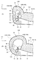
これに対し、図3(A)に示される従来例のように、外側展開部18A及び内側展開部18Bがパッド本体部40と同一(又は同様)のウレタンフォームのみによって構成されている場合、サイドエアバッグ30の膨張時には、ドア側サイド部14Bが、図3(B)に示されるような形状に変形することになる。この場合、以下の(1)〜(3)の理由により、縫製部22の開裂が遅くなり、その結果としてサイドエアバッグ30の展開が遅れてしまう。
(1)シート表皮20が伸びる。
(2)外側展開部18A及び内側展開部18B(ウレタンフォーム)が潰れる。
(3)外側展開部18A及び内側展開部18Bとシート表皮20が、シートバック14の上下方向から見て円形断面形状に変形する。
On the other hand, as in the conventional example shown in FIG. 3A, when the outer expanded
(1) The
(2) The outer developed
(3) The outer developed
上記のうち(1)については、所謂力布を追加することにより解消することができる。また、(2)については、背景技術の欄で説明した構造のように、外側展開部18Aの材料として硬質なウレタンフォーム等を用いることにより、ある程度は解消することができるが、完全に解消することはできない。
Of the above, (1) can be solved by adding a so-called wadding. Further, (2) can be solved to some extent by using hard urethane foam or the like as the material of the
この点、本実施形態では、外側展開部18A及び内側展開部18Bの一部を構成するダイラタント部材44、46が、サイドエアバッグ30からの衝撃力によって瞬時に硬化することにより、上記(1)〜(3)の問題を全て解消することができる。しかも、ダイラタント部材44、46は、通常時には軟質であるため、シートバック16の座り心地が悪化することがなく好適である。
In this respect, in the present embodiment, the
また、本実施形態では、インフレータ28がサイドエアバッグ30内の後端部に配設されているため、サイドエアバッグ30は、インフレータ28よりも車両前方側へ膨張するが、ダイラタント部材46の後端は、シートバック14の上下方向から見たインフレータ28の中心Cよりも車両後方側に配置されている。これにより、サイドエアバッグ30がダイラタント部材46の後端とインフレータ28との間へ膨張する(入り込む)ことを防止できる。
Further, in the present embodiment, since the inflator 28 is disposed at the rear end portion in the
次に、本発明の他の実施形態について説明する。なお、前記第1実施形態と基本的に同様の構成・作用については、前記第1実施形態と同符号を付与し、その説明を省略する。 Next, another embodiment of the present invention will be described. In addition, about the structure and effect | action similar to the said 1st Embodiment, the same code | symbol as the said 1st Embodiment is provided, and the description is abbreviate | omitted.
<第2の実施形態>
図4には、本発明の第2実施形態に係る車両用シートの部分的な構成が図2と同様の横断面図にて示されている。この実施形態は、前記第1実施形態と基本的に同様の構成とされている。但し、この実施形態では、外側展開部18A及び内側展開部18Bの全部が、ダイラタント部材44、46によって構成されている。この実施形態では、サイドエアバッグ30からの衝撃力によってダイラタント部材44、46が硬化することにより、外側展開部18A及び内側展開部18B並びにこれらを被覆するシート表皮20の変形を略完全に防止することができるため、縫製部22を一層迅速に開裂させることができる。
<Second Embodiment>
FIG. 4 shows a partial configuration of a vehicle seat according to the second embodiment of the present invention in a cross-sectional view similar to FIG. This embodiment has basically the same configuration as the first embodiment. However, in this embodiment, all of the outer expanded
<第3の実施形態>
図5には、本発明の第3実施形態に係る車両用シートの部分的な構成が図2と同様の横断面図にて示されている。この実施形態は、前記第1実施形態と基本的に同様の構成とされている。但し、この実施形態では、前記第1実施形態に係るダイラタント部材46が省略されており、内側展開部18Bがパッド本体部40と同一のウレタンフォームのみによって構成されている。
<Third Embodiment>
FIG. 5 shows a partial configuration of a vehicle seat according to the third embodiment of the present invention in a cross-sectional view similar to FIG. This embodiment has basically the same configuration as the first embodiment. However, in this embodiment, the
この実施形態では、内側展開部18Bがサイドエアバッグ30の膨張圧によって変形することを抑制できないため、サイドエアバッグ30の展開早期化効果は減少するが、ドア側サイド部14Bがサイドドア等に押されて乗員側に侵入してきた際には、ウレタンフォームからなる内側展開部18Bが乗員に干渉することになる。この場合、当該内側展開部18Bが低荷重で変形することにより、乗員に加わる荷重を低減することができる。なお、本実施形態は、車体の強度が高い等の理由でサイドエアバッグの展開時間に猶予がある車両に対して特に有効である。
In this embodiment, the
<第4の実施形態>
図6には、本発明の第4実施形態に係る車両用シートの部分的な構成が図2と同様の横断面図にて示されている。この実施形態は、前記第3実施形態と基本的に同様の構成とされている。但し、この実施形態では、外側展開部18Aの全部がダイラタント部材44によって構成されている。この実施形態においても前記第3実施形態と同様の効果を奏する。しかも、サイドエアバッグ30からの衝撃力によってダイラタント部材44が硬化することにより、外側展開部18A及びこれを被覆するシート表皮20の変形を略完全に防止することができる。
<Fourth Embodiment>
FIG. 6 shows a partial configuration of a vehicle seat according to the fourth embodiment of the present invention in a cross-sectional view similar to FIG. This embodiment has basically the same configuration as the third embodiment. However, in this embodiment, the entire
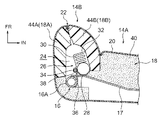
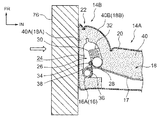
<第5の実施形態>
図7には、本発明の第5実施形態に係る車両用シートの部分的な構成が図2と同様の横断面図にて示されている。この実施形態は、前記第4実施形態と基本的に同様の構成とされている。但し、この実施形態では、フレームサイド部16Aが板金材料によって形成されており、空洞部24の内壁にはフェルト50が配設されている。また、この実施形態では、外側展開部18Aを構成するダイラタント部材44とシート表皮20との間に力布52が配設されている。この力布52は、一端部が縫製部22に縫合されると共に他端部がフレームサイド部16Aに係止されており、ダイラタント部材44は、サイドエアバッグ30(サイドエアバッグモジュール26)と力布52との間に配置されている。この力布52は、サイドエアバッグ30の膨張圧を受けて伸張することにより当該膨張圧を縫製部22に伝達する(集中させる)ものである。
<Fifth Embodiment>
FIG. 7 shows a partial configuration of a vehicle seat according to the fifth embodiment of the present invention in a cross-sectional view similar to FIG. This embodiment has basically the same configuration as the fourth embodiment. However, in this embodiment, the
この実施形態では、サイドエアバッグ30が膨張する際には、サイドエアバッグ30からの衝撃力によってダイラタント部材44が瞬時に硬化することにより、力布52を迅速に伸張させることができる。つまり、ダイラタント部材44の代わりに通常のパッド材(ウレタンフォームなど)が配設されている場合には、当該パッド材の変形により力布52の伸張が遅れることになるが、本発明では力布52の迅速な伸張によって縫製部22に早期にバッグ膨張圧を伝達することができる。これにより、縫製部22の開裂を一層早めることができる。
In this embodiment, when the
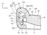
<第6の実施形態>
図8には、本発明の第6実施形態に係る車両用シートの部分的な構成が図2と同様の横断面図にて示されている。この実施形態は、前記第5施形態と基本的に同様の構成とされており、外側展開部18Aを構成するダイラタント部材44とシート表皮20との間に力布52が配設されている。なお、図8において、54は、力布52を支持するための支持ブラケットである。この実施形態においても前記第5実施形態と基本的に同様の作用効果を奏する。
<Sixth Embodiment>
FIG. 8 shows a partial configuration of a vehicle seat according to the sixth embodiment of the present invention in a cross-sectional view similar to FIG. This embodiment has basically the same configuration as that of the fifth embodiment, and a
<第7の実施形態>
図9には、本発明の第7実施形態に係る車両用シートの部分的な構成が図2と同様の横断面図にて示されている。この実施形態は、前記第1実施形態と基本的に同様の構成とされている。但し、この実施形態では、フレームサイド部16Aが板金材料によって形成されており、エアバッグモジュール26は、エアバッグケース56を備えている。また、この実施形態では、折り畳み状態のサイドエアバッグ30の後部が、インフレータ28に対して車両幅方向外側に配置されており、ダイラタント部材44の後端部は、サイドエアバッグ30の後端よりも車両後方側に延長されている。さらに、この実施形態では、パッド外側部40Aとダイラタント部材44との間には、力布58が配置されており、パッド内側部40Bとダイラタント部材46との間には、力布60が配置されている。力布58は、一端部が縫製部22に縫合されると共に、他端部がフレームサイド部16Aに締結固定された金具62に係止されている。また、力布60は、一端部が縫製部22に縫合されると共に、他端部がフレームサイド部16Aに締結固定された金具64に係止されている。これらの力布58、60は、サイドエアバッグ30の膨張圧を受けて伸張することにより当該膨張圧を縫製部22に伝達するものである。
<Seventh Embodiment>
FIG. 9 shows a partial configuration of a vehicle seat according to the seventh embodiment of the present invention in a cross-sectional view similar to FIG. This embodiment has basically the same configuration as the first embodiment. However, in this embodiment, the
この実施形態では、サイドエアバッグ30が膨張する際には、サイドエアバッグ30からの衝撃力によってダイラタント部材44、46が瞬時に硬化することにより、力布58、60を迅速に伸張させることができる。これにより、縫製部22の開裂を一層早めることができる。
In this embodiment, when the
<第8の実施形態>
図10には、本発明の第8実施形態に係る車両用シートの部分的な構成が図2と同様の横断面図にて示されている。この実施形態は、前記第5実施形態及び前記第6実施形態と基本的に同様の構成とされている。但し、この実施形態では、パッド内側部40Bとエアバッグモジュール26との間には、力布66が配置されている。この力布66は、一端部が縫製部22に縫合されると共に、他端部がフレームサイド部16Aに係止されており、サイドエアバッグ30の膨張圧を受けて伸張することにより当該膨張圧を縫製部22に伝達するものである。なお、図10において、68はエアバッグケースであり、70は不織布である。この実施形態では、前記第5実施形態及び第6実施形態と基本的に同様の作用効果を奏する。しかも、力布66が追加されているため、縫製部22の開裂を一層早めることができる。
<Eighth Embodiment>
FIG. 10 shows a partial configuration of a vehicle seat according to the eighth embodiment of the present invention in a cross-sectional view similar to FIG. This embodiment has basically the same configuration as the fifth embodiment and the sixth embodiment. However, in this embodiment, a
<第9の実施形態>
図11には、本発明の第9実施形態に係る車両用シートの部分的な構成が図2と同様の横断面図にて示されている。この実施形態は、前記第1実施形態と基本的に同様の構成とされている。但し、この実施形態では、ダイラタント部材44とエアバッグモジュール26との間には、力布72が配置されており、ダイラタント部材46とエアバッグモジュール26との間には、力布74が配置されている。これらの力布72、74は、各一端部が縫製部22に縫合されている。また、力布72は、他端側がフレームサイド部16Aに巻き掛けられており、力布72の他端部と力布74の他端部が縫合されている。これにより、力布72、74の他端側が直接又は間接的にフレームサイド部16Aに係止(支持)されている。これらの力布72、74は、サイドエアバッグ30の膨張圧を受けて伸張することにより当該膨張圧を縫製部22に伝達するものである。
<Ninth Embodiment>
FIG. 11 shows a partial configuration of a vehicle seat according to the ninth embodiment of the present invention in a cross-sectional view similar to FIG. This embodiment has basically the same configuration as the first embodiment. However, in this embodiment, a
この実施形態では、サイドエアバッグ30が膨張する際には、サイドエアバッグ30からの衝撃力が力布72、74を介してダイラタント部材44、46に加えられることにより、ダイラタント部材44、46が瞬時に硬化し、力布72、74及びシート表皮20の変形が抑制される。これにより、シート表皮20の縫製部22に早期にバッグ膨張圧を伝達することができるので、縫製部22の開裂を一層早めることができる。
In this embodiment, when the
<第10の実施形態>
図12には、本発明の第10実施形態に係る車両用シートの部分的な構成が図2と同様の横断面図にて示されている。この実施形態は、前記第4実施形態と基本的に同様の構成とされている。但し、この実施形態では、ダイラタント部材44は、後端部が車両後方側に延長されており、フレームサイド部16Aに対して車両幅方向外側にオーバーラップして配置された侵入抑制部44Aを備えている。
<Tenth Embodiment>
FIG. 12 shows a partial configuration of a vehicle seat according to the tenth embodiment of the present invention in a cross-sectional view similar to FIG. This embodiment has basically the same configuration as the fourth embodiment. However, in this embodiment, the
この実施形態では、車両の側面衝突時に、車体側部76(サイドドアやピラーなど)がシートバック14のドア側サイド部14Bに衝突すると、その衝撃力によりダイラタント部材44が瞬時に硬化する。このダイラタント部材44は、フレームサイド部16Aに対して車両幅方向外側にオーバーラップして配置された侵入抑制部44Aを備えているため、フレームサイド部16Aと車体側部76との間に、硬化した侵入抑制部44Aが介在することにより、車両幅方向内側(乗員側)への車体側部76の侵入が抑制される。これにより、車体側部76によって乗員が直接押されることを抑制できると共に、サイドエアバッグ30の展開スペースを十分に確保することができる。
In this embodiment, when the vehicle body side part 76 (side door, pillar, etc.) collides with the door
つまり、図13に示されるように、侵入抑制部44A(ダイラタント部材44)が省略されている場合、パッド外側部40Aが車体側部76からの荷重によって容易に潰されてしまう。このため、車体側部76が衝突の初期に車両幅方向内側へ大きく侵入してくることにより、車体側部76によって乗員が直接押されたり、サイドエアバッグ30の展開スペースが狭められてしまうが、本実施形態ではこれを回避することができる。
That is, as shown in FIG. 13, when the
なお、前記第5実施形態に係る車両用シート(図7参照)においても、ダイラタント44の一部がフレームサイド部16Aに対して車両幅方向外側にオーバーラップして配置されているため、本第10実施形態と同様の作用効果を得ることができる。
In the vehicle seat according to the fifth embodiment (see FIG. 7), a part of the dilatant 44 is disposed so as to overlap the
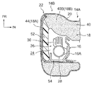
<第11の実施形態>
図14には、本発明の第11実施形態に係る車両用シートの部分的な構成が図2と同様の横断面図にて示されている。この実施形態は、前記第6実施形態と基本的に同様の構成とされているが、この実施形態では、ダイラタント部材44が、フレームサイド部16Aに対して車両幅方向外側にオーバーラップして配置された侵入抑制部44Aを備えている。したがって、この実施形態においても前記第10実施形態と基本的に同様の作用効果を得ることができる。
<Eleventh embodiment>
FIG. 14 shows a partial configuration of a vehicle seat according to the eleventh embodiment of the present invention in a cross-sectional view similar to FIG. This embodiment has basically the same configuration as that of the sixth embodiment, but in this embodiment, the
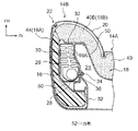
<第12の実施形態>
図15には、本発明の第12実施形態に係る車両用シートの部分的な構成が図2と同様の横断面図にて示されている。この実施形態は、前記第7実施形態と基本的に同様の構成とされているが、この実施形態では、ダイラタント部材44が、フレームサイド部16Aに対して車両幅方向外側にオーバーラップして配置された侵入抑制部44Aを備えている。さらに、この実施形態では、前述した「d3oTM」によって形成され、ダイラタント部材44、インフレータ28及びフレームサイド部16Aに対して車両幅方向外側にオーバーラップして配置されたダイラタント部材78を備えている。したがって、この実施形態においても前記第10実施形態と基本的に同様の作用効果を得ることができる。
<Twelfth Embodiment>
FIG. 15 shows a partial configuration of a vehicle seat according to the twelfth embodiment of the present invention in a cross-sectional view similar to FIG. This embodiment has basically the same configuration as that of the seventh embodiment, but in this embodiment, the
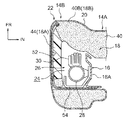
<第13の実施形態>
図16には、本発明の第13実施形態に係る車両用シートの部分的な構成が図2と同様の横断面図にて示されている。この実施形態は、前記第7実施形態と基本的に同様の構成とされているが、この実施形態では、前述した「d3oTM」によって形成され、インフレータ28及びフレームサイド部16Aに対して車両幅方向外側にオーバーラップして配置されたダイラタント部材80を備えている。したがって、この実施形態においても前記第10実施形態と基本的に同様の作用効果を得ることができる。
<13th Embodiment>
FIG. 16 shows a partial configuration of a vehicle seat according to a thirteenth embodiment of the present invention in a cross-sectional view similar to FIG. This embodiment has basically the same configuration as that of the seventh embodiment, but in this embodiment, it is formed by the aforementioned “d3o TM ” and has a vehicle width with respect to the inflator 28 and the
なお、上記各実施形態では、ダイラタント部材(44、46、78、80)が、外側展開部18A及び内側展開部18Bの両方、又は外側展開部18Aだけに設けられた構成にしたが、請求項1〜請求項4に係る発明はこれに限らず、ダイラタント部材が内側展開部18Bだけに設けられた構成にしてもよい。また、上記各実施形態おいて、ダイラタント部材(44、46、78、80)とサイドエアバッグモジュール26との間にパッド本体部40を構成するウレタンフォーム等が介在された構成にしてもよい。
In each of the above-described embodiments, the dilatant member (44, 46, 78, 80) is configured to be provided in both the
また、上記各実施形態では、ダイラタント部材(44、46、78、80)がパッド本体部40と一体発砲成形された構成にしたが、請求項1〜請求項5に係る発明はこれに限らず、ダイラタント部材がパッド本体部40とは別に成形されて、パッド本体部40に取り付けられる(接着等される)構成にしてもよい。
In each of the above embodiments, the dilatant member (44, 46, 78, 80) is integrally formed with the pad
なお、上記各実施形態では、本発明が自動車のフロントシートに対して適用された場合にすいて説明したが、これに限らず、本発明は自動車等の車両のリヤシートに対しても適用することができる。 In each of the above embodiments, the case where the present invention is applied to a front seat of an automobile has been described. However, the present invention is not limited to this, and the present invention is also applied to a rear seat of a vehicle such as an automobile. Can do.
その他、本発明は、その要旨を逸脱しない範囲で種々変更して実施できる。また、本発明の権利範囲が上記各実施形態に限定されないことはいうでもない。 In addition, the present invention can be implemented with various modifications without departing from the scope of the invention. Further, it goes without saying that the scope of rights of the present invention is not limited to the above embodiments.
10 車両用シート
14 シートバック
16 フレーム
18 シートバックパッド
18A 外側展開部
18B 内側展開部
20 シート表皮
22 縫製部
24 空洞部
28 インフレータ
30 サイドエアバッグ
46 ダイラタント部材
52 力布
60 力布
66 力布
74 力布
78 ダイラタント部材
80 ダイラタント部材
DESCRIPTION OF
Claims (5)
前記シートバックパッドを被覆すると共に、前記サイド部の前端側に配置された部位に縫製部が設けられたシート表皮と、
前記空洞部内に配設され、インフレータから発生したガスによって膨張すると共に、前記サイド部の前部側において前記シートバックパッドを車両幅方向外側の外側展開部と当該外側展開部よりも車両幅方向内側の内側展開部とに展開させつつ前記縫製部を開裂させて車両前方側へ展開するサイドエアバッグと、
を備え、
前記外側展開部及び前記内側展開部の少なくとも一部がダイラタント特性を有する材料からなるダイラタント部材によって構成されている車両用シート。 A seat back pad that constitutes a cushion material for the seat back and has a hollow portion formed in a side portion on the outer side in the vehicle width direction of the seat back;
Covering the seat back pad, and a seat skin provided with a sewing portion at a portion disposed on the front end side of the side portion;
The seat back pad is disposed in the hollow portion and is expanded by the gas generated from the inflator, and the seat back pad is disposed on the front side of the side portion in the vehicle width direction outside and in the vehicle width direction inside the outside spread portion. A side airbag that is deployed to the vehicle front side by cleaving the sewing portion while being deployed to the inner deployment portion of the vehicle,
With
A vehicle seat in which at least a part of the outer spread part and the inner spread part is constituted by a dilatant member made of a material having a dilatant characteristic.
Priority Applications (1)
| Application Number | Priority Date | Filing Date | Title |
|---|---|---|---|
| JP2010292207A JP2012140044A (en) | 2010-12-28 | 2010-12-28 | Vehicular seat |
Applications Claiming Priority (1)
| Application Number | Priority Date | Filing Date | Title |
|---|---|---|---|
| JP2010292207A JP2012140044A (en) | 2010-12-28 | 2010-12-28 | Vehicular seat |
Publications (1)
| Publication Number | Publication Date |
|---|---|
| JP2012140044A true JP2012140044A (en) | 2012-07-26 |
Family
ID=46676802
Family Applications (1)
| Application Number | Title | Priority Date | Filing Date |
|---|---|---|---|
| JP2010292207A Pending JP2012140044A (en) | 2010-12-28 | 2010-12-28 | Vehicular seat |
Country Status (1)
| Country | Link |
|---|---|
| JP (1) | JP2012140044A (en) |
Cited By (11)
| Publication number | Priority date | Publication date | Assignee | Title |
|---|---|---|---|---|
| WO2013137355A1 (en) * | 2012-03-16 | 2013-09-19 | テイ・エス テック株式会社 | Cushion pad and vehicle seat |
| CN103963731A (en) * | 2013-01-25 | 2014-08-06 | 丰田合成株式会社 | Side airbag apparatus |
| KR20150062388A (en) * | 2013-11-29 | 2015-06-08 | 현대모비스 주식회사 | Side airbag apparatus |
| KR20160058485A (en) * | 2014-11-17 | 2016-05-25 | 현대모비스 주식회사 | Installation structure of side airbag |
| CN107458271A (en) * | 2016-06-06 | 2017-12-12 | 福特全球技术公司 | The conformal seat of passive type with hybrid air/liquid room |
| JP2018070096A (en) * | 2016-11-04 | 2018-05-10 | テイ・エス テック株式会社 | Vehicle seat |
| WO2018083919A1 (en) * | 2016-11-04 | 2018-05-11 | テイ・エス テック株式会社 | Vehicle seat |
| JP2018094928A (en) * | 2016-12-07 | 2018-06-21 | トヨタ自動車株式会社 | Curtain airbag device for vehicle |
| EP3521109A1 (en) * | 2018-02-06 | 2019-08-07 | Autoliv Development AB | Side airbag apparatus |
| JP2019173182A (en) * | 2018-03-26 | 2019-10-10 | 京セラ株式会社 | Posture maintaining device |
| CN114585542A (en) * | 2019-11-20 | 2022-06-03 | 奥托立夫开发公司 | Side airbag device |
-
2010
- 2010-12-28 JP JP2010292207A patent/JP2012140044A/en active Pending
Cited By (24)
| Publication number | Priority date | Publication date | Assignee | Title |
|---|---|---|---|---|
| WO2013137355A1 (en) * | 2012-03-16 | 2013-09-19 | テイ・エス テック株式会社 | Cushion pad and vehicle seat |
| CN103963731A (en) * | 2013-01-25 | 2014-08-06 | 丰田合成株式会社 | Side airbag apparatus |
| CN103963731B (en) * | 2013-01-25 | 2016-05-25 | 丰田合成株式会社 | Side air bag device |
| KR102149648B1 (en) * | 2013-11-29 | 2020-08-31 | 현대모비스 주식회사 | Side airbag apparatus |
| KR20150062388A (en) * | 2013-11-29 | 2015-06-08 | 현대모비스 주식회사 | Side airbag apparatus |
| KR20160058485A (en) * | 2014-11-17 | 2016-05-25 | 현대모비스 주식회사 | Installation structure of side airbag |
| KR102269369B1 (en) * | 2014-11-17 | 2021-06-25 | 현대모비스 주식회사 | Installation structure of side airbag |
| CN107458271A (en) * | 2016-06-06 | 2017-12-12 | 福特全球技术公司 | The conformal seat of passive type with hybrid air/liquid room |
| CN107458271B (en) * | 2016-06-06 | 2021-08-31 | 福特全球技术公司 | Passive form-fitting seat with hybrid air/liquid chamber |
| JP2018070096A (en) * | 2016-11-04 | 2018-05-10 | テイ・エス テック株式会社 | Vehicle seat |
| JP2021151864A (en) * | 2016-11-04 | 2021-09-30 | テイ・エス テック株式会社 | Vehicle seat |
| US11702024B2 (en) | 2016-11-04 | 2023-07-18 | Ts Tech Co., Ltd. | Vehicle seat |
| CN109863059A (en) * | 2016-11-04 | 2019-06-07 | 提爱思科技股份有限公司 | Auto use chair |
| US11040686B2 (en) | 2016-11-04 | 2021-06-22 | Ts Tech Co., Ltd. | Vehicle seat |
| JP2023073310A (en) * | 2016-11-04 | 2023-05-25 | テイ・エス テック株式会社 | vehicle seat |
| WO2018083919A1 (en) * | 2016-11-04 | 2018-05-11 | テイ・エス テック株式会社 | Vehicle seat |
| JP7248919B2 (en) | 2016-11-04 | 2023-03-30 | テイ・エス テック株式会社 | vehicle seat |
| CN109863059B (en) * | 2016-11-04 | 2022-04-19 | 提爱思科技股份有限公司 | Vehicle seat |
| CN114763086A (en) * | 2016-11-04 | 2022-07-19 | 提爱思科技股份有限公司 | Vehicle seat |
| JP2018094928A (en) * | 2016-12-07 | 2018-06-21 | トヨタ自動車株式会社 | Curtain airbag device for vehicle |
| EP3521109A1 (en) * | 2018-02-06 | 2019-08-07 | Autoliv Development AB | Side airbag apparatus |
| JP2019173182A (en) * | 2018-03-26 | 2019-10-10 | 京セラ株式会社 | Posture maintaining device |
| CN114585542A (en) * | 2019-11-20 | 2022-06-03 | 奥托立夫开发公司 | Side airbag device |
| CN114585542B (en) * | 2019-11-20 | 2023-11-24 | 奥托立夫开发公司 | Side airbag device |
Similar Documents
| Publication | Publication Date | Title |
|---|---|---|
| JP2012140044A (en) | Vehicular seat | |
| KR102069226B1 (en) | Passenger protection device for front passenger seat | |
| JP5408360B2 (en) | Fixing structure of rear side airbag device for vehicle | |
| JP4760533B2 (en) | Airbag device | |
| JP6435412B2 (en) | Crew protection device | |
| JP4187721B2 (en) | Improved vehicle seat | |
| KR101080728B1 (en) | Side airbag apparatus for vehicles | |
| EP2199158B1 (en) | Side airbag structure and method of assembling it | |
| KR101775857B1 (en) | Vehicular seat | |
| JP5907135B2 (en) | Side airbag device for vehicle | |
| JP5807567B2 (en) | Side airbag device for vehicle | |
| JP5850008B2 (en) | Air belt device | |
| JP2008087631A (en) | Side airbag device | |
| JPWO2018179850A1 (en) | Crew protection device | |
| JP5195852B2 (en) | Vehicle seat | |
| JP2011011733A (en) | Vehicular roof air bag device | |
| JP5036519B2 (en) | Seat for vehicle with built-in side airbag device | |
| JP2008201297A (en) | Vehicle side airbag device | |
| JP2019104258A (en) | Vehicle seat | |
| WO2020049882A1 (en) | Side airbag device | |
| JP6769382B2 (en) | Vehicle seats equipped with side airbag devices | |
| JP5365433B2 (en) | Airbag device for passenger seat | |
| JPWO2019073826A1 (en) | Side airbag device | |
| JP5505279B2 (en) | Airbag device | |
| JP4640325B2 (en) | Side airbag device for vehicle |