WO2015141801A1 - 受信装置 - Google Patents
受信装置 Download PDFInfo
- Publication number
- WO2015141801A1 WO2015141801A1 PCT/JP2015/058344 JP2015058344W WO2015141801A1 WO 2015141801 A1 WO2015141801 A1 WO 2015141801A1 JP 2015058344 W JP2015058344 W JP 2015058344W WO 2015141801 A1 WO2015141801 A1 WO 2015141801A1
- Authority
- WO
- WIPO (PCT)
- Prior art keywords
- unit
- power
- null
- interference
- null symbol
- Prior art date
Links
Images


Classifications
-
- H—ELECTRICITY
- H04—ELECTRIC COMMUNICATION TECHNIQUE
- H04J—MULTIPLEX COMMUNICATION
- H04J11/00—Orthogonal multiplex systems, e.g. using WALSH codes
- H04J11/0023—Interference mitigation or co-ordination
- H04J11/0066—Interference mitigation or co-ordination of narrowband interference
-
- H—ELECTRICITY
- H04—ELECTRIC COMMUNICATION TECHNIQUE
- H04B—TRANSMISSION
- H04B1/00—Details of transmission systems, not covered by a single one of groups H04B3/00 - H04B13/00; Details of transmission systems not characterised by the medium used for transmission
- H04B1/06—Receivers
- H04B1/10—Means associated with receiver for limiting or suppressing noise or interference
- H04B1/1027—Means associated with receiver for limiting or suppressing noise or interference assessing signal quality or detecting noise/interference for the received signal
- H04B1/1036—Means associated with receiver for limiting or suppressing noise or interference assessing signal quality or detecting noise/interference for the received signal with automatic suppression of narrow band noise or interference, e.g. by using tuneable notch filters
-
- H—ELECTRICITY
- H04—ELECTRIC COMMUNICATION TECHNIQUE
- H04J—MULTIPLEX COMMUNICATION
- H04J11/00—Orthogonal multiplex systems, e.g. using WALSH codes
- H04J11/0023—Interference mitigation or co-ordination
-
- H—ELECTRICITY
- H04—ELECTRIC COMMUNICATION TECHNIQUE
- H04L—TRANSMISSION OF DIGITAL INFORMATION, e.g. TELEGRAPHIC COMMUNICATION
- H04L27/00—Modulated-carrier systems
- H04L27/26—Systems using multi-frequency codes
- H04L27/2601—Multicarrier modulation systems
- H04L27/2602—Signal structure
- H04L27/2605—Symbol extensions, e.g. Zero Tail, Unique Word [UW]
-
- H—ELECTRICITY
- H04—ELECTRIC COMMUNICATION TECHNIQUE
- H04L—TRANSMISSION OF DIGITAL INFORMATION, e.g. TELEGRAPHIC COMMUNICATION
- H04L27/00—Modulated-carrier systems
- H04L27/26—Systems using multi-frequency codes
- H04L27/2601—Multicarrier modulation systems
- H04L27/2647—Arrangements specific to the receiver only
-
- H—ELECTRICITY
- H04—ELECTRIC COMMUNICATION TECHNIQUE
- H04B—TRANSMISSION
- H04B1/00—Details of transmission systems, not covered by a single one of groups H04B3/00 - H04B13/00; Details of transmission systems not characterised by the medium used for transmission
- H04B1/06—Receivers
- H04B1/10—Means associated with receiver for limiting or suppressing noise or interference
- H04B1/1027—Means associated with receiver for limiting or suppressing noise or interference assessing signal quality or detecting noise/interference for the received signal
- H04B2001/1054—Means associated with receiver for limiting or suppressing noise or interference assessing signal quality or detecting noise/interference for the received signal by changing bandwidth
Definitions
- the present invention relates to a receiving device of a wireless communication system.
- Patent Document 1 discloses a technique in which a null symbol is randomly inserted in an OFDM (Orthogonal Frequency Division Multiplexing) method and interference power is measured using the null symbol.
- OFDM Orthogonal Frequency Division Multiplexing
- interference waves such as narrowband interference whose frequency is narrower than the signal bandwidth, burst interference which is shorter in time than the packet length, and interference which is a sine wave but fluctuates in frequency in a short time like a microwave oven. If these interference types cannot be known in advance, optimal filtering cannot be performed when measuring interference power from null symbols. For this reason, even if the interference resistance performance is high for a certain type of interference, there is a problem that the interference resistance performance decreases for another type of interference.
- the present invention has been made in view of the above, and an object of the present invention is to obtain a receiving apparatus with high interference resistance.
- the present invention is a receiving device that receives a signal including a null symbol, and includes a null extracting unit that extracts a null symbol from the received signal, and the null A power calculating means for calculating the power of each null symbol extracted by the extracting means; a plurality of types of filtering are executed on the power of each null symbol calculated by the power calculating means; Filtering means to be obtained; and normalizing means to normalize data symbols included in the received signal based on a value obtained by performing non-linear processing on the average power value obtained by the filtering means.
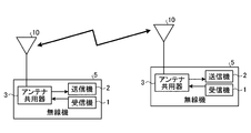
- FIG. 1 is a diagram illustrating a configuration example of a wireless communication system to which a receiving device according to the present invention is applied.
- FIG. 2 is a diagram illustrating a configuration example of a wireless device.
- FIG. 3 is a diagram illustrating a configuration example of a transmitter.
- FIG. 4 is a diagram illustrating a configuration example of a receiver.
- FIG. 5 is a diagram illustrating an example of a signal in which a null symbol is inserted.
- FIG. 6 is a diagram illustrating an example of a weighting factor as a filter characteristic of the two-dimensional filter unit.
- FIG. 7 is a diagram illustrating an example of the filter calculation.
- FIG. 8 is a diagram illustrating a configuration example of the two-dimensional filter unit.
- FIG. 9 is a diagram illustrating an example of characteristics (weighting coefficients) of the two-dimensional filter.
- FIG. 1 is a diagram illustrating a configuration example of a wireless communication system to which a receiving device according to the present invention is applied.
- the radio communication system includes a plurality of base stations 6 and a plurality of mobile stations 7, and each of the base stations 6 and the mobile stations 7 includes a radio device 5 and an antenna 10.
- Each of the plurality of base stations 6 is connected to the wired network 8.
- the mobile station 7 is a device in which the radio device 5 is mounted on a transportation means (moving body) such as an automobile, a railway vehicle, an aircraft, and a ship. Further, there may be a form in which a person carries the same radio device 5 as that constituting the mobile station 7.
- the receiving device constitutes a radio device 5.
- Each base station 6 is in an area called a cell, and communicates with a plurality of mobile stations 7 in the area.
- the mobile station 7 can communicate with a communication partner on the wired network 8 via the base station 6.
- communication can be continued by switching the connection with the base station 6.
- FIG. 2 is a diagram illustrating a configuration example of the wireless device 5.
- an antenna 10 is connected to the wireless device 5, and a receiver 1, a transmitter 2, and an antenna duplexer 3 are provided therein.
- the antenna duplexer 3 is a switch that switches between transmission and reception, and in the case of frequency division sharing, the antenna duplexer 3 is a filter that separates transmission and reception frequencies.
- two wireless devices 5 that transmit and receive wireless signals to each other are described, but one of the wireless devices 5 is mounted on the base station 6 and the other wireless device 5 is mounted on the mobile station 7. Has been.
- FIG. 3 is a diagram illustrating a configuration example of the transmitter 2.
- the transmitter 2 includes an RF unit 21, an IFFT unit 22, a null addition unit 23, a modulation unit 24, and an error correction coding unit 25.
- the error correction encoding unit 25 encodes the transmission data
- the modulation unit 24 modulates the encoded transmission data according to a modulation scheme such as QPSK or QAM.
- the error correction encoding unit 25 may be realized by dedicated hardware or software.
- a program for operating as the error correction encoding unit 25 is executed by a processor such as a CPU (Central Processing Unit) or a system LSI (Large Scale Integration). Realize.
- a processor such as a CPU (Central Processing Unit) or a system LSI (Large Scale Integration). Realize.
- the null adding unit 23 adds null to the modulated transmission data, and the IFFT unit 22 performs IFFT (Inverse Fast Fourier Transform) on the transmission data after the null addition to perform OFDM modulation.
- the RF unit 21 converts the transmission data after OFDM modulation into a high frequency and outputs it.
- FIG. 4 is a diagram illustrating a configuration example of the receiver 1.
- the receiver 1 includes an RF unit 11, an FFT unit 12, a null extraction unit 13, a power calculation unit 14, a two-dimensional filter unit 15, a normalization unit 16, a demodulation unit 17, and an error correction decoding unit 18. ing.
- the RF unit 11 converts the received signal into a baseband signal, and then the FFT unit 12 decomposes into subcarriers for each OFDM symbol. To do.
- the null extraction unit 13 extracts a null symbol from a signal for each symbol and for each OFDM subcarrier (an output signal from the FFT unit 12), and a complex signal that is a null symbol extracted by the null extraction unit 13 by the power conversion unit 14
- the power value I 2 + Q 2 of (I + Qj) is calculated, and the two-dimensional filter unit 15 averages the power value in the time frequency domain.
- the normalization unit 16 normalizes a non-null signal portion (data signal portion) in the output signal from the FFT unit 12 using the average power value calculated by the two-dimensional filter unit 15. Normalization is performed by dividing by the square root of the power value (average power value output from the two-dimensional filter unit 15).
- the average power value of the null symbol part is the interference power itself, and a symbol having a large interference power has a small weight, so that interference is suppressed.
- the signal (data component) is also suppressed at the same time as the interference, but after the demodulation unit 17 demodulates the signal output from the normalization unit 16, the error correction decoding unit 18 performs the decoding process to recover. Can do.
- the error correction decoding unit 18 may be realized by dedicated hardware or software. When the error correction decoding unit 18 is realized by software, for example, it is realized by a processor executing a program for operating as the error correction decoding unit 18.
- FIG. 5 is a diagram illustrating an example of a signal in which a null symbol is inserted (added). A signal (data symbol) is transmitted where it is not a null symbol.
- FIG. 6 is a diagram illustrating an example of a weighting factor as a filter characteristic of the two-dimensional filter unit 15. FIG. 6 shows a filter having a characteristic in which all weights are 1 in a 7 ⁇ 7 time frequency domain.
- FIG. 7 is a diagram illustrating an example of a filter operation when the signal illustrated in FIG. 5 is filtered using the filter having the characteristics illustrated in FIG.
- the interference power at point A (data symbol to which A is assigned) is the average of the power at the null point (null symbol to which B is assigned) in a 7 ⁇ 7 region centering on point A.
- FIG. 8 is a diagram illustrating a configuration example of the two-dimensional filter unit 15.
- the two-dimensional filter unit 15 includes a first two-dimensional filter 151, a second two-dimensional filter 152, a third two-dimensional filter 153, and a maximum value selection unit 154.
- Each two-dimensional filter (the first two-dimensional filter 151, the second two-dimensional filter 152, and the third two-dimensional filter 153) has different characteristics.
- the maximum value selection unit 154 selects and outputs the maximum power value among the power values output from each two-dimensional filter. Since each two-dimensional filter is a filter suitable for different types of interference, it is possible to cope with different types of interference by setting the maximum value as interference power.
- FIG. 9 is a diagram illustrating an example of characteristics (weighting factors) of each two-dimensional filter.
- the first two-dimensional filter 151 is equally weighted in the time frequency domain in the range of 3 ⁇ 15
- the second two-dimensional filter 152 is equally weighted in the time frequency domain in the range of 7 ⁇ 7.
- the filter and the third two-dimensional filter 153 are equal weight filters in the range of 15 ⁇ 3 in the time frequency domain.
- the first two-dimensional filter 151 has a high time resolution and a low frequency resolution. Therefore, the performance is high for interference with fast time fluctuation, but the performance is low for narrowband interference.
- the third two-dimensional filter 153 has a low time resolution and a high frequency resolution.
- the second two-dimensional filter 152 has intermediate characteristics between the first two-dimensional filter 151 and the third two-dimensional filter 153.
- FIG. 8 shows a configuration example of the two-dimensional filter unit 15 including three types of two-dimensional filters having different characteristics.
- the configuration includes four or more types of two-dimensional filters and two types of two-dimensional filters. It is good also as a structure.
- the receiving apparatus performs filtering using a plurality of filters having different characteristics in a two-dimensional filter process for averaging received power in a plurality of null symbols in the time-frequency domain.
- the configuration described in the above embodiment shows an example of the contents of the present invention, and can be combined with another known technique, and can be combined with other configurations without departing from the gist of the present invention. It is also possible to omit or change the part.
- the receiving apparatus is useful as a receiving apparatus that constitutes a communication apparatus (base station, mobile station, etc.) that transmits and receives a radio signal in which a null symbol is inserted.
- a communication apparatus base station, mobile station, etc.
Abstract
Description
図1は、本発明にかかる受信装置を適用した無線通信システムの構成例を示す図である。無線通信システムは、複数の基地局6と複数の移動局7を含んで構成されており、これらの基地局6と移動局7は、それぞれ無線機5およびアンテナ10を備える。複数の基地局6はそれぞれ有線ネットワーク8に接続される。移動局7は、例えば自動車や鉄道車両、航空機、船舶などの交通手段(移動体)に無線機5が搭載されたものである。また、移動局7を構成しているものと同様の無線機5を人が持ち運ぶ形態もあり得る。図1では記載を省略しているが、受信装置は無線機5を構成している。
Claims (4)
- ヌルシンボルが含まれた信号を受信する受信装置であって、
受信した信号からヌルシンボルを抽出するヌル抽出手段と、
前記ヌル抽出手段で抽出された各ヌルシンボルの電力を計算する電力計算手段と、
前記電力計算手段で計算された各ヌルシンボルの電力に対して複数種類のフィルタリングを実行し、複数種類の電力平均値を求めるフィルタ手段と、
前記フィルタ手段が求めた前記電力平均値の非線形処理を行った値に基づいて、前記受信した信号に含まれているデータシンボルを規格化する規格化手段と、
を備えることを特徴とする受信装置。 - 前記フィルタ手段は、時間周波数領域においてフィルタリングを実行することを特徴とする請求項1に記載の受信装置。
- 前記複数種類のフィルタリングは、狭帯域干渉により受信信号に付加された干渉成分の電力平均値を算出するためのフィルタリングと、バースト干渉により受信信号に付加された干渉成分の電力平均値を算出するためのフィルタリングと、を含むことを特徴とする請求項1または2に記載の受信装置。
- マルチキャリア無線伝送システムを構成することを特徴とする請求項1、2または3に記載の受信装置。
Priority Applications (4)
| Application Number | Priority Date | Filing Date | Title |
|---|---|---|---|
| US15/126,383 US9762345B2 (en) | 2014-03-19 | 2015-03-19 | Receiving device |
| JP2016508809A JP6157722B2 (ja) | 2014-03-19 | 2015-03-19 | 受信装置 |
| EP15764201.8A EP3121978A4 (en) | 2014-03-19 | 2015-03-19 | Receiving device |
| CN201580013371.6A CN106105069B (zh) | 2014-03-19 | 2015-03-19 | 接收装置 |
Applications Claiming Priority (2)
| Application Number | Priority Date | Filing Date | Title |
|---|---|---|---|
| JP2014056711 | 2014-03-19 | ||
| JP2014-056711 | 2014-03-19 |
Publications (1)
| Publication Number | Publication Date |
|---|---|
| WO2015141801A1 true WO2015141801A1 (ja) | 2015-09-24 |
Family
ID=54144763
Family Applications (1)
| Application Number | Title | Priority Date | Filing Date |
|---|---|---|---|
| PCT/JP2015/058344 WO2015141801A1 (ja) | 2014-03-19 | 2015-03-19 | 受信装置 |
Country Status (5)
| Country | Link |
|---|---|
| US (1) | US9762345B2 (ja) |
| EP (1) | EP3121978A4 (ja) |
| JP (1) | JP6157722B2 (ja) |
| CN (1) | CN106105069B (ja) |
| WO (1) | WO2015141801A1 (ja) |
Families Citing this family (3)
| Publication number | Priority date | Publication date | Assignee | Title |
|---|---|---|---|---|
| WO2019234932A1 (ja) * | 2018-06-08 | 2019-12-12 | 三菱電機株式会社 | 無線送信装置、無線受信装置、無線通信装置、無線通信システムおよび無線送信方法 |
| WO2020183544A1 (ja) * | 2019-03-08 | 2020-09-17 | 三菱電機株式会社 | 受信装置、無線通信システムおよび干渉電力推定方法 |
| DE112020006273B4 (de) * | 2020-02-25 | 2024-01-04 | Mitsubishi Electric Corporation | Interferenz-Löscheinrichtung, Steuerschaltung, Speichermedium und Interferenz-Mittenfrequenz-Schätzverfahren |
Citations (3)
| Publication number | Priority date | Publication date | Assignee | Title |
|---|---|---|---|---|
| JP2002135230A (ja) * | 2000-10-24 | 2002-05-10 | Mitsubishi Electric Corp | スペクトラム拡散通信システムの送信機、受信機、ならびにその変復調方法 |
| JP2011234259A (ja) * | 2010-04-30 | 2011-11-17 | Sharp Corp | 基地局装置、端末装置および無線通信システム |
| JP2013539266A (ja) * | 2010-08-03 | 2013-10-17 | クゥアルコム・インコーポレイテッド | 無線通信のために改善された干渉推定 |
Family Cites Families (9)
| Publication number | Priority date | Publication date | Assignee | Title |
|---|---|---|---|---|
| JP2772286B2 (ja) | 1996-08-30 | 1998-07-02 | 株式会社次世代デジタルテレビジョン放送システム研究所 | 直交周波数分割多重信号復調装置 |
| JP3802031B2 (ja) | 2004-02-16 | 2006-07-26 | パイオニア株式会社 | 受信装置及び受信方法 |
| KR100897769B1 (ko) * | 2007-01-24 | 2009-05-15 | 삼성전자주식회사 | 채널 상태 정보 추정방법 및 그 장치 |
| CN101636947A (zh) | 2007-02-15 | 2010-01-27 | 三菱电机株式会社 | 通信装置以及传送控制方法 |
| KR20090120518A (ko) * | 2007-03-19 | 2009-11-24 | 코닌클리케 필립스 일렉트로닉스 엔.브이. | 인컴번트 신호들에 대한 fft 기반의 파일럿 감지 |
| US7873123B2 (en) * | 2007-07-30 | 2011-01-18 | Alpha Imaging Technology Corp. | Null detector and method thereof |
| CN102138293A (zh) * | 2008-08-27 | 2011-07-27 | 株式会社Ntt都科摩 | 移动台和移动通信方法 |
| US8855000B2 (en) | 2011-04-28 | 2014-10-07 | Qualcomm Incorporated | Interference estimation using data traffic power and reference signal power |
| WO2015045585A1 (ja) | 2013-09-24 | 2015-04-02 | 三菱電機株式会社 | 無線通信装置、送信装置および受信装置 |
-
2015
- 2015-03-19 CN CN201580013371.6A patent/CN106105069B/zh active Active
- 2015-03-19 EP EP15764201.8A patent/EP3121978A4/en not_active Withdrawn
- 2015-03-19 JP JP2016508809A patent/JP6157722B2/ja active Active
- 2015-03-19 WO PCT/JP2015/058344 patent/WO2015141801A1/ja active Application Filing
- 2015-03-19 US US15/126,383 patent/US9762345B2/en active Active
Patent Citations (3)
| Publication number | Priority date | Publication date | Assignee | Title |
|---|---|---|---|---|
| JP2002135230A (ja) * | 2000-10-24 | 2002-05-10 | Mitsubishi Electric Corp | スペクトラム拡散通信システムの送信機、受信機、ならびにその変復調方法 |
| JP2011234259A (ja) * | 2010-04-30 | 2011-11-17 | Sharp Corp | 基地局装置、端末装置および無線通信システム |
| JP2013539266A (ja) * | 2010-08-03 | 2013-10-17 | クゥアルコム・インコーポレイテッド | 無線通信のために改善された干渉推定 |
Non-Patent Citations (1)
| Title |
|---|
| See also references of EP3121978A4 * |
Also Published As
| Publication number | Publication date |
|---|---|
| EP3121978A4 (en) | 2017-12-06 |
| US20170085334A1 (en) | 2017-03-23 |
| JPWO2015141801A1 (ja) | 2017-04-13 |
| CN106105069A (zh) | 2016-11-09 |
| JP6157722B2 (ja) | 2017-07-05 |
| CN106105069B (zh) | 2018-09-07 |
| EP3121978A1 (en) | 2017-01-25 |
| US9762345B2 (en) | 2017-09-12 |
Similar Documents
| Publication | Publication Date | Title |
|---|---|---|
| US10142084B2 (en) | Full-duplex self-interference cancellation | |
| US11528175B2 (en) | Uplink measurements for wireless systems | |
| KR20090108134A (ko) | 주파수 코딩을 강화한 다중반송파 변조 | |
| US9479379B2 (en) | Narrowband OFDM (NOFDM) transceiver for powerline communications (PLC) | |
| US20230388071A1 (en) | Adaptation of secure sounding signal to bandwidth variation | |
| JP6157722B2 (ja) | 受信装置 | |
| US20210067285A1 (en) | Enhanced bandwidth selection for wireless communication devices | |
| CN101502030B (zh) | Ofdm通信装置以及保护间隔长度确定方法 | |
| US10404506B2 (en) | Methods and devices for interference variance estimation and interference cancellation | |
| WO2017010623A1 (ko) | 무선통신 시스템에서 비선형 자기간섭 채널을 추정하기 위한 방법 및 이를 위한 장치 | |
| EP3552322A1 (en) | Wireless devices and systems including examples of cross correlating wireless transmissions | |
| WO2010053985A2 (en) | Processing information blocks for wireless transmission | |
| CN101753502A (zh) | 一种信号处理方法及信号处理装置 | |
| Xu et al. | Non-orthogonal waveform scheduling for next generation narrowband IoT | |
| CN101562484B (zh) | 一种适用于ofdm系统的信道质量测量方法 | |
| US9215122B2 (en) | Radio communication apparatus and interference signal detection method | |
| KR101619164B1 (ko) | 단일반송파 주파수분할다중접속 시스템에서 최소평균제곱오류 수신 방법 및 장치 | |
| US9413563B2 (en) | Method and apparatus for channel estimation using localized SINR in wireless communication systems | |
| Xu et al. | Experimental validations on self interference cancelled non-orthogonal SEFDM signals | |
| Singh et al. | Implementation of OFDM and other multicarrier modulations on SDR | |
| Dusza et al. | Error vector magnitude measurement accuracy and impact on spectrum flatness behavior for OFDM-based WiMAX and LTE systems | |
| Kumar et al. | OFDM-Based Packet Transceiver on Usrp Using Labview | |
| Gökceli et al. | Implementation of pre-FFT beamforming in MIMO-OFDM | |
| JP5380995B2 (ja) | 無線受信装置及び方法 | |
| CN114697166A (zh) | 相位噪声的估计方法、装置及系统 |
Legal Events
| Date | Code | Title | Description |
|---|---|---|---|
| 121 | Ep: the epo has been informed by wipo that ep was designated in this application |
Ref document number: 15764201 Country of ref document: EP Kind code of ref document: A1 |
|
| ENP | Entry into the national phase |
Ref document number: 2016508809 Country of ref document: JP Kind code of ref document: A |
|
| REEP | Request for entry into the european phase |
Ref document number: 2015764201 Country of ref document: EP |
|
| WWE | Wipo information: entry into national phase |
Ref document number: 15126383 Country of ref document: US Ref document number: 2015764201 Country of ref document: EP |
|
| NENP | Non-entry into the national phase |
Ref country code: DE |