WO2015141561A1 - ノズル、バーナ、燃焼器、ガスタービン、ガスタービンシステム - Google Patents
ノズル、バーナ、燃焼器、ガスタービン、ガスタービンシステム Download PDFInfo
- Publication number
- WO2015141561A1 WO2015141561A1 PCT/JP2015/057378 JP2015057378W WO2015141561A1 WO 2015141561 A1 WO2015141561 A1 WO 2015141561A1 JP 2015057378 W JP2015057378 W JP 2015057378W WO 2015141561 A1 WO2015141561 A1 WO 2015141561A1
- Authority
- WO
- WIPO (PCT)
- Prior art keywords
- air
- nozzle
- combustor
- flow path
- main
- Prior art date
- Legal status (The legal status is an assumption and is not a legal conclusion. Google has not performed a legal analysis and makes no representation as to the accuracy of the status listed.)
- Ceased
Links
Images



Classifications
-
- F—MECHANICAL ENGINEERING; LIGHTING; HEATING; WEAPONS; BLASTING
- F23—COMBUSTION APPARATUS; COMBUSTION PROCESSES
- F23R—GENERATING COMBUSTION PRODUCTS OF HIGH PRESSURE OR HIGH VELOCITY, e.g. GAS-TURBINE COMBUSTION CHAMBERS
- F23R3/00—Continuous combustion chambers using liquid or gaseous fuel
- F23R3/28—Continuous combustion chambers using liquid or gaseous fuel characterised by the fuel supply
- F23R3/286—Continuous combustion chambers using liquid or gaseous fuel characterised by the fuel supply having fuel-air premixing devices
-
- F—MECHANICAL ENGINEERING; LIGHTING; HEATING; WEAPONS; BLASTING
- F02—COMBUSTION ENGINES; HOT-GAS OR COMBUSTION-PRODUCT ENGINE PLANTS
- F02C—GAS-TURBINE PLANTS; AIR INTAKES FOR JET-PROPULSION PLANTS; CONTROLLING FUEL SUPPLY IN AIR-BREATHING JET-PROPULSION PLANTS
- F02C7/00—Features, components parts, details or accessories, not provided for in, or of interest apart form groups F02C1/00 - F02C6/00; Air intakes for jet-propulsion plants
- F02C7/22—Fuel supply systems
-
- F—MECHANICAL ENGINEERING; LIGHTING; HEATING; WEAPONS; BLASTING
- F02—COMBUSTION ENGINES; HOT-GAS OR COMBUSTION-PRODUCT ENGINE PLANTS
- F02C—GAS-TURBINE PLANTS; AIR INTAKES FOR JET-PROPULSION PLANTS; CONTROLLING FUEL SUPPLY IN AIR-BREATHING JET-PROPULSION PLANTS
- F02C7/00—Features, components parts, details or accessories, not provided for in, or of interest apart form groups F02C1/00 - F02C6/00; Air intakes for jet-propulsion plants
- F02C7/22—Fuel supply systems
- F02C7/232—Fuel valves; Draining valves or systems
-
- F—MECHANICAL ENGINEERING; LIGHTING; HEATING; WEAPONS; BLASTING
- F23—COMBUSTION APPARATUS; COMBUSTION PROCESSES
- F23D—BURNERS
- F23D14/00—Burners for combustion of a gas, e.g. of a gas stored under pressure as a liquid
- F23D14/46—Details
- F23D14/72—Safety devices, e.g. operative in case of failure of gas supply
- F23D14/82—Preventing flashback or blowback
-
- F—MECHANICAL ENGINEERING; LIGHTING; HEATING; WEAPONS; BLASTING
- F23—COMBUSTION APPARATUS; COMBUSTION PROCESSES
- F23R—GENERATING COMBUSTION PRODUCTS OF HIGH PRESSURE OR HIGH VELOCITY, e.g. GAS-TURBINE COMBUSTION CHAMBERS
- F23R3/00—Continuous combustion chambers using liquid or gaseous fuel
- F23R3/02—Continuous combustion chambers using liquid or gaseous fuel characterised by the air-flow or gas-flow configuration
- F23R3/04—Air inlet arrangements
- F23R3/10—Air inlet arrangements for primary air
- F23R3/12—Air inlet arrangements for primary air inducing a vortex
- F23R3/14—Air inlet arrangements for primary air inducing a vortex by using swirl vanes
-
- F—MECHANICAL ENGINEERING; LIGHTING; HEATING; WEAPONS; BLASTING
- F23—COMBUSTION APPARATUS; COMBUSTION PROCESSES
- F23R—GENERATING COMBUSTION PRODUCTS OF HIGH PRESSURE OR HIGH VELOCITY, e.g. GAS-TURBINE COMBUSTION CHAMBERS
- F23R3/00—Continuous combustion chambers using liquid or gaseous fuel
- F23R3/02—Continuous combustion chambers using liquid or gaseous fuel characterised by the air-flow or gas-flow configuration
- F23R3/16—Continuous combustion chambers using liquid or gaseous fuel characterised by the air-flow or gas-flow configuration with devices inside the flame tube or the combustion chamber to influence the air or gas flow
-
- F—MECHANICAL ENGINEERING; LIGHTING; HEATING; WEAPONS; BLASTING
- F23—COMBUSTION APPARATUS; COMBUSTION PROCESSES
- F23R—GENERATING COMBUSTION PRODUCTS OF HIGH PRESSURE OR HIGH VELOCITY, e.g. GAS-TURBINE COMBUSTION CHAMBERS
- F23R3/00—Continuous combustion chambers using liquid or gaseous fuel
- F23R3/28—Continuous combustion chambers using liquid or gaseous fuel characterised by the fuel supply
-
- F—MECHANICAL ENGINEERING; LIGHTING; HEATING; WEAPONS; BLASTING
- F05—INDEXING SCHEMES RELATING TO ENGINES OR PUMPS IN VARIOUS SUBCLASSES OF CLASSES F01-F04
- F05D—INDEXING SCHEME FOR ASPECTS RELATING TO NON-POSITIVE-DISPLACEMENT MACHINES OR ENGINES, GAS-TURBINES OR JET-PROPULSION PLANTS
- F05D2240/00—Components
- F05D2240/35—Combustors or associated equipment
Definitions
- the present invention relates to a nozzle used in a combustor, a burner, a combustor, a gas turbine, and a gas turbine system.
- a premixed combustion system in which fuel is mixed in advance with compressed air (combustion air) sent from a compressor to generate an air-fuel mixture and the air-fuel mixture is burned is widely used. See, for example, Patent Documents 1 to 3.
- this type of combustor one having a pilot nozzle provided on a central axis of the combustor and a plurality of main nozzles disposed in parallel with the pilot nozzle is known.
- backfire may occur in which the flame reverses in the flow direction of the mixture in a region where the flow velocity of the mixture is low.
- Patent Document 4 discloses a configuration in which a fluid injection hole for injecting a fluid such as air is provided in the vicinity of the downstream end of a swirler which is provided on the outer peripheral side of a main nozzle and which swirls compressed air fed from a compressor. It is disclosed. In this configuration, by injecting the fluid at high speed from the fluid injection hole, the area where the flow velocity of the mixture is low is reduced, and the fuel concentration at the downstream end is reduced to suppress the occurrence of flashback.
- a fluid injection hole for injecting a fluid such as air is provided in the vicinity of the downstream end of a swirler which is provided on the outer peripheral side of a main nozzle and which swirls compressed air fed from a compressor. It is disclosed. In this configuration, by injecting the fluid at high speed from the fluid injection hole, the area where the flow velocity of the mixture is low is reduced, and the fuel concentration at the downstream end is reduced to suppress the occurrence of flashback.
- JP 2000-46333 A Japanese Patent No. 3139978 JP-A-8-261466 JP, 2011-17334, A
- the region where the occurrence of flashback can be suppressed by the fluid injection is limited.
- the tip of the main nozzle can not exert the effect of suppressing the occurrence of flashback due to the injection of fluid.
- the present invention provides a nozzle, a burner, a combustor, a gas turbine, and a gas turbine system that can reliably suppress flashback to the nozzle tip.
- the nozzle is a nozzle of a combustor that injects fuel, and includes an air injection unit that injects air from the tip.
- the burner comprises the above-mentioned nozzle and injects fuel.
- the combustor is a combustor provided with the burner in the second aspect, and covers the nozzle from the outer peripheral side and forms an air flow path between the burner and the nozzle. And a pressure loss portion provided in the air flow path and causing pressure loss in air flowing through the air flow path, and the nozzle takes in air from the outer peripheral surface on the upstream side of the pressure loss portion.
- An intake part, and a flow path formation part which forms a flow path which leads the air taken in from the air intake part to the air injection part.
- the combustor is provided with a plurality of air intake portions in the third aspect on the outer peripheral surface of the nozzle, and the flow path forming portion includes air taken in from the plurality of air intake portions.
- a merging unit may be provided to be merged upstream of the air injection unit.
- the flow path forming portion in the third aspect may form a flow path having an annular cross section.
- the flow path forming portion in the third aspect may form a plurality of flow paths arranged concentrically.
- a gas turbine includes a combustor according to any one of the third to fifth aspects, and a turbine main body having a rotor rotated by combustion gas delivered from the combustor. Equipped with
- a gas turbine system in an eighth aspect of the present invention, includes a combustor provided with a nozzle in the first aspect, a turbine body provided with a rotor that is rotated by combustion gas delivered from the combustor, and a cabin of the turbine body.
- a casing air supply unit for supplying the air to the air injection unit; a control valve for controlling the supply of the air from the compartment to the air injection unit in the casing air supply unit; It has a detection part which detects generation
- the nozzle According to the nozzle, the burner, the combustor, the gas turbine, and the gas turbine system described above, it is possible to reliably suppress flashback to the nozzle tip.
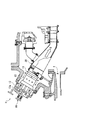
- FIG. 1 is a half sectional view showing a schematic configuration of a gas turbine of this embodiment.
- FIG. 2 is a cross-sectional view showing a combustor provided in the gas turbine.
- FIG. 3 is a cross-sectional view showing the configuration of the combustor.
- a gas turbine 1 of this embodiment includes a compressor 2, a plurality of combustors 10, and a turbine (turbine main body) 3.
- the compressor 2 takes in air as a working fluid from an air intake to generate compressed air.
- the combustor 10 is connected to the discharge port of the compressor 2.
- the combustor 10 injects fuel into the compressed air discharged from the compressor 2 to generate high temperature / high pressure combustion gas.
- the turbine 3 converts the thermal energy of the combustion gas delivered from the combustor 10 into rotational energy of the rotor 3 a to generate a driving force.
- the turbine 3 transmits the generated driving force to a generator (not shown) connected to the rotor 3a.
- each combustor 10 includes a combustor body 11 and a transition piece 30.
- the combustor body 11 functions as a combustion chamber for reacting the supplied fuel with the compressed air A.
- the transition piece 30 accelerates the flow velocity of the combustion gas B flowing in from the combustor main body 11 and introduces it into the downstream turbine 3.
- the combustor body 11 includes an inner cylinder 12 and an outer cylinder 13.
- the inner cylinder 12 is formed in a cylindrical shape.
- the outer cylinder 13 is concentrically provided on the outer peripheral side of one end side in the central axis direction of the inner cylinder 12.
- the compressed air A which has flowed into the combustor body 11 from between the outer cylinder 13 and the inner cylinder 12, is rotated 180 ° at one end 13 a of the outer cylinder 13 and supplied to the inside of the inner cylinder 12.
- the combustor main body 11 includes a pilot burner 21 and a main burner (burner) 22 in the inner cylinder 12.
- the pilot burner 21 is provided along the central axis O of the inner cylinder 12.
- the pilot burner 21 injects the fuel supplied from the outside from the tip 21 a.
- the pilot burner 21 generates a flame by igniting the injected fuel.
- the pilot burner 21 is provided with a pilot cone 24.
- the pilot cone 24 is formed in a tubular shape surrounding the outer peripheral side of the tip end portion 21 a of the pilot burner 21.
- the pilot cone 24 has a tapered cone portion 24 c whose inside diameter gradually expands in the direction of flame generation from the vicinity of the tip 21 a of the pilot burner 21.
- the tapered cone portion 24c regulates the diffusion range and direction of the flame to enhance the flame stability.
- a plurality of main burners 22 are provided in the inner cylinder 12.
- the main burners 22 are arranged on the outer peripheral side of the pilot burner 21 at intervals in the circumferential direction.
- Each main burner 22 extends parallel to the central axis O of the inner cylinder 12.
- a main nozzle (nozzle) 25 is provided at the tip of the main burner 22.
- the main nozzle 25 has a conical shape whose outer diameter gradually reduces toward the tip 25s.
- the main burner 22 is provided with a cone member (cylindrical member) 26 on the outer peripheral side of the main nozzle 25.
- the cone member 26 is cylindrical and provided so as to surround the main nozzle 25 from the outer peripheral side.
- the cone member 26 is formed such that a side 26a close to the pilot cone 24 on the center side of the inner cylinder 12 is gradually inclined toward the outer peripheral side toward the flame generation direction.
- the cone member 26 forms a main flow passage R1 in which the compressed air A flows with the main burner 22.
- the main burner 22 includes a main swirler (pressure loss portion) 27 in the cone member 26.
- the main swirler 27 applies a swirling force to the flow in the main flow passage R1.
- fuel main fuel
- the fuel nozzle (not shown) may be provided at a portion other than the main swirler 27, for example, at a portion downstream of the air intake 52 described later on the outer peripheral surface side of the main burner 22.
- This fuel is mixed with the compressed air A in the inner cylinder 12 to form a premixed mixture F.
- the swirling flow generated by the main swirler 27 causes the premixed air F to flow around the main burner 22 and flow downstream in the main flow passage R1.
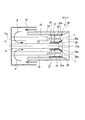
- FIG. 4 is a cross-sectional view showing the configuration of the main nozzle of the combustor.
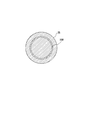
- FIG. 5 is a cross-sectional view orthogonal to the axis of the main nozzle.
- the main nozzle 25 includes a flow passage hole (flow passage forming portion) 50, an air injection port (air injection portion) 51, and an air intake (air intake portion) 52. .
- the flow passage hole 50 extends in the axial direction of the main nozzle 25. As shown in FIGS. 4 and 5, in this embodiment, a plurality of flow passage holes 50 are formed. The flow passage holes 50 are arranged at intervals in the circumferential direction of the main nozzle 25. The flow passage holes 50 are disposed concentrically with the main nozzle 25. Although the case where three flow path holes 50 are formed is illustrated in FIG. 5, two or more flow path holes may be formed. The plurality of flow passage holes 50 constitute the flow passage forming portion of the present invention.
- the air injection port 51 is formed to open at the tip 25 s of the main nozzle 25.
- a plurality of air inlets 52 are formed on the outer peripheral surface of the main nozzle 25.
- Each air intake port 52 is formed by opening one end of the flow path hole 50 on the outer peripheral surface of the main nozzle 25.
- Each air intake port 52 opens upstream of the main swirler 27 on the outer peripheral surface of the main nozzle 25.
- the plurality of flow passage holes 50 merge into one at a merging portion 54 in the main nozzle 25 and communicate with one air injection port 51.
- the flow passage hole 50 guides the compressed air A taken from the air intake 52 on the upstream side of the main swirler 27 to the jet air flow passage R2 for guiding the compressed air A to the air injection opening 51 of the tip 25s of the main nozzle 25.
- a portion of the compressed air A flowing through the main flow passage R1 flows from the air intake 52 into the flow passage hole 50, and the air injection opening of the tip 25s of the main nozzle 25 It spouts from 51.
- the compressed air A is injected from the air injection port 51, the fuel concentration of the premixed air F in the vicinity of the tip portion 25s of the main nozzle 25 decreases. Further, the flow velocity of the premixed air F at the tip portion 25 s of the main nozzle 25 is increased by the compressed air A injected from the air injection port 51.
- the main nozzle 25 has an air intake port 52 on the upstream side of the main swirler 27, and has an air injection port 51 of the tip 25s of the main nozzle 25 on the downstream side of the main swirler 27.
- a pressure difference is generated between the air inlet 52 and the air injection port 51 due to the pressure loss in the main swirler 27.
- the pressure on the air intake 52 side is higher than that on the air injection port 51 side.
- the front end of the main nozzle 25 is The fuel concentration of the premixed gas F decreases near the portion 25s. Therefore, it is difficult for the flame to occur at the tip 25s of the in-nozzle 25.
- the compressed air A injected from the air injection port 51 increases the flow velocity of the premixed air F at the tip 25s of the main nozzle 25. Therefore, when a flashback occurs, it becomes difficult for the flame to go upstream toward the tip 25s of the main nozzle 25. In this way, it is possible to reliably suppress the ascension and generation of flashback to the tip 25s of the main nozzle 25. As a result, burnout of the main nozzle 25 can also be avoided.
- the flow path hole 50 communicating with the air injection port 51 has the air intake port 52 on the upstream side of the main swirler 27, and the air injection port 51 of the tip 25 s of the main nozzle 25 on the downstream side of the main swirler 27.
- air can be favorably taken into the jet air flow path R2 from the air intake 52. Thereby, suppression of flashback can be performed reliably and efficiently.
- the main nozzle 25 has a plurality of sets of air intake ports 52 and flow path holes 50, and these are joined at the joining portion 54.
- the air taken in from the plurality of air intake ports 52 passes through the jet air flow path R2 formed in the flow path holes 50 and merges at the merging portion 54. Thereafter, the merged air is injected from the air injection port 51. Therefore, the amount of air injection from the air injection port 51 can be increased.
- the flow path forming portion forms the plurality of flow path holes 50 concentrically, the flow path cross-sectional area can be easily enlarged, and the workability of the flow path forming portion can also be improved.
- FIG. 6 is a view showing a modification of the main nozzle.
- the flow path hole 50B may have an annular cross-sectional shape. This can be realized by making the main nozzle 25 a double pipe structure. By configuring in this manner, it is possible to easily increase the cross-sectional area of the flow path and secure a sufficient cross-sectional area of the flow path, as compared with the case where the plurality of flow path holes 50 are arranged in parallel. Thereby, the air injection amount from the air injection port 51 can be increased.
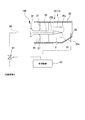
- FIG. 7 is a view showing a schematic configuration of a gas turbine system according to a second embodiment.
- the gas turbine system 100 in this embodiment includes a combustor 10, a turbine 3 (see FIG. 1), a casing air supply pipe (casing air supply unit) 60, and a control valve 61. , A detection sensor (detection unit) 62, and a control device 63.
- the main nozzle 25B of the main burner 22 provided in the combustor 10 is provided with an air injection port 51 at the tip end 25s.
- the main nozzle 25B is formed with a flow passage hole 50 whose one end is in communication with the air injection port 51.
- the casing air supply pipe 60 is connected to the other end of the flow passage hole 50 of the main nozzle 25B.
- the cabin air supply pipe 60 supplies the compressed air A in the cabin of the turbine 3 to the air injection port 51. As a result, air is injected from the air injection port 51 of the main nozzle 25B.
- the control valve 61 is provided in the casing air supply pipe 60.
- the control valve 61 controls the supply of the compressed air A from the compartment in the casing air supply pipe 60 to the air injection port 51 by performing the opening and closing operation.
- the detection sensor 62 detects the occurrence of flashback in the combustor 10.
- a temperature sensor, a pressure sensor, a light intensity sensor or the like provided in the vicinity of the main nozzle 25B of the main burner 22 can be used.
- the detection sensor 62 detects temperature, pressure, light intensity and the like in the vicinity of the main nozzle 25 B, and outputs the detection data to the control device 63.
- the controller 63 controls opening and closing of the control valve 61 based on the detection result of the detection sensor 62.
- the control device 63 monitors changes in parameters such as temperature, pressure, and light intensity in the vicinity of the main nozzle 25B detected by the detection sensor 62, and determines whether flashback occurs in the vicinity of the main nozzle 25B. Then, when it is determined that flashback has occurred, the control device 63 is configured to open the control valve 61.
- the control valve 61 is opened, the compressed air A in the cabin of the turbine 3 is supplied to the air injection port 51 through the cabin air supply pipe 60.
- the control device 63 may open the control valve 61 to inject air from the air injection port 51 of the main nozzle 25B when the operating state of the gas turbine 1 becomes a predetermined state.
- the compressed air A is injected from the air injection port 51 when, for example, a flashback occurs or the flashback is likely to occur under the control of the control device 63. be able to.
- the control device 63 it is possible to suppress the occurrence of flashback of the flashback to the tip 25s of the main nozzle 25 and the occurrence of flashback.
- By performing such control it is possible to stop the injection of air from the air injection port 51 when not required.
- the main swirler 27 is used as the pressure loss portion in the above embodiment, the present invention is not limited to this. Any configuration may be used as long as the air flowing through the air flow passage can cause a pressure loss.
- the present invention can be applied to a nozzle, a burner, a combustor, a gas turbine, and a gas turbine system, and can reliably suppress flashback to the nozzle tip.
Landscapes
- Engineering & Computer Science (AREA)
- Chemical & Material Sciences (AREA)
- Combustion & Propulsion (AREA)
- Mechanical Engineering (AREA)
- General Engineering & Computer Science (AREA)
- Gas Burners (AREA)
- Nozzles For Spraying Of Liquid Fuel (AREA)
- Pre-Mixing And Non-Premixing Gas Burner (AREA)
Abstract
Description
本願は、2014年3月20日に、日本に出願された特願2014-059127号に基づき優先権を主張し、その内容をここに援用する。
この種の燃焼器としては、燃焼器の中心軸線上に設けられたパイロットノズルと、このパイロットノズルと平行に配置された複数のメインノズルとを有するものが知られている。
遡上した火炎がノズル先端近傍で停滞すると、ノズル先端が焼損してしまう可能性がある。
この発明は、ノズル先端部への逆火を確実に抑制することのできるノズル、バーナ、燃焼器、ガスタービン、ガスタービンシステムを提供する。
(第一実施形態)
図1は、この実施形態のガスタービンの概略構成を示す半断面図である。図2は、上記ガスタービンに備えられた燃焼器を示す断面図である。図3は、上記燃焼器の構成を示す断面図である。
図1に示すように、この実施形態のガスタービン1は、圧縮機2と、複数の燃焼器10と、タービン(タービン本体)3と、を備える。
燃焼器10は、圧縮機2の吐出口に接続されている。燃焼器10は、圧縮機2から吐出された圧縮空気に燃料を噴射して高温・高圧の燃焼ガスを発生させる。
タービン3は、燃焼器10から送り出された燃焼ガスの熱エネルギをロータ3aの回転エネルギに変換して駆動力を発生させる。このタービン3は、発生させた駆動力をロータ3aに連結された発電機(図示無し)に伝達する。
外筒13と内筒12との間から燃焼器本体11内に流入した圧縮空気Aは、外筒13の一端側13aで180°転回し、内筒12の内部に供給される。
メインバーナ22は、メインバーナ22の外周面側に、例えばメインスワラ27に設けられた燃料ノズル(図示無し)から燃料(メイン燃料)が噴射される。燃料ノズル(図示無し)は、メインスワラ27以外の部位、例えばメインバーナ22の外周面側において後述する空気取入口52よりも下流側の部位等に設けても良い。この燃料は、内筒12内の圧縮空気Aと混合され、予混合気Fとなる。メインスワラ27により生成された旋回流によって、予混合気Fはメインバーナ22周りに旋回しながら主流路R1を下流に向けて流れていく。
図4に示すように、メインノズル25は、流路孔(流路形成部)50と、空気噴射口(空気噴射部)51と、空気取入口(空気取入部)52と、を備えている。
空気取入口52は、メインノズル25の外周面に複数形成されている。各空気取入口52は、それぞれ流路孔50の一端が、メインノズル25の外周面に開口することで形成されている。各空気取入口52は、メインノズル25の外周面において、メインスワラ27よりも上流側に開口している。
このようにして、メインノズル25の先端部25sへの逆火の遡上および発生を確実に抑制することが可能となる。その結果、メインノズル25の焼損も避けることができる。
上記第一実施形態では、メインノズル25は、流路孔50を複数備えているが、これに限らない。
図6は、上記メインノズルの変形例を示す図である。
図6に示すように、流路孔50Bは、断面形状が円環状をなすようにしても良い。これは、メインノズル25を二重管構造とすることで実現できる。
このように構成することで、複数本の流路孔50を並設する場合と比較して、容易に流路断面積を大きくして十分な流路断面積を確保することができる。これにより、空気噴射口51からの空気噴射量を増大させることができる。
次に、この発明にかかるガスタービンシステムについて説明する。以下に説明する第二実施形態においては、第一実施形態と同一部分に同一符号を付して説明するとともに、重複説明を省略する。
図7は、第二実施形態におけるガスタービンシステムの概略構成を示す図である。
図7に示すように、この実施形態におけるガスタービンシステム100は、燃焼器10と、タービン3(図1参照)と、車室空気供給管(車室空気供給部)60と、制御弁61と、検出センサ(検出部)62と、制御装置63と、を備える。
制御弁61が開放されると、車室空気供給管60を通して、タービン3の車室内の圧縮空気Aが空気噴射口51に供給される。これにより、メインノズル25Bの空気噴射口51から空気が噴射され、メインノズル25の先端部25sへの逆火の遡上および逆火の発生を抑制することが可能となる。その結果、メインノズル25の焼損を避けることができる。
このような制御を行うことで、不要時においては、空気噴射口51からの空気の噴射を停止させることができる。
上記実施形態で、メインスワラ27を圧力損失部としたが、これに限らない。空気流路を流れる空気に圧力損失を生じさせることができるのであれば、いかなる構成としても良い。
2 圧縮機
3 タービン(タービン本体)
3a ロータ
10 燃焼器
11 燃焼器本体
12 内筒
13 外筒
13a 一端側
21 パイロットバーナ
21a 先端部
22 メインバーナ(バーナ)
24 パイロットコーン
24c テーパコーン部
25,25B メインノズル(ノズル)
25s 先端部
26 コーン部材(筒状部材)
27 メインスワラ(圧力損失部)
30 尾筒
50,50B 流路孔(流路形成部)
51 空気噴射口(空気噴射部)
52 空気取入口(空気取入部)
54 合流部
60 車室空気供給管(車室空気供給部)
61 制御弁
62 検出センサ(検出部)
63 制御装置
100 ガスタービンシステム
A 圧縮空気
B 燃焼ガス
F 予混合気
O 中心軸
R1 主流路
R2 噴出空気流路
Claims (8)
- 燃料を噴射する燃焼器のノズルであって、
先端部から空気を噴射させる空気噴射部を備えるノズル。 - 請求項1に記載のノズルを備え、燃料を噴射するバーナ。
- 請求項2に記載のバーナを備える燃焼器であって、
前記ノズルを外周側から覆うと共に、前記ノズルとの間に空気流路を形成する筒状部材と、
前記空気流路に設けられ、前記空気流路を流れる空気に圧力損失を生じさせる圧力損失部と、を備え、
前記ノズルは、
前記圧力損失部よりも上流側の外周面から空気を取り入れる空気取入部と、
前記空気取入部から取り入れた空気を前記空気噴射部まで導く流路を形成する流路形成部と、を備える燃焼器。 - 前記空気取入部は、前記ノズルの外周面に複数設けられ、
前記流路形成部は、複数の前記空気取入部から取り入れた空気を、前記空気噴射部の上流側で合流させる合流部を備える請求項3に記載の燃焼器。 - 前記流路形成部は、断面円環状の流路を形成する請求項3に記載の燃焼器。
- 前記流路形成部は、同心円上に配される複数の流路を形成する請求項3に記載の燃焼器。
- 請求項3から5の何れか一項に記載の燃焼器と、
前記燃焼器から送り出された燃焼ガスにより回転するロータを備えたタービン本体と、を備えるガスタービン。 - 請求項1に記載のノズルを備える燃焼器と、
前記燃焼器から送り出された燃焼ガスにより回転するロータを備えたタービン本体と、
前記タービン本体の車室内の空気を前記空気噴射部に供給する車室空気供給部と、
前記車室空気供給部における前記車室から前記空気噴射部への前記空気の供給を制御する制御弁と、
前記燃焼器における逆火の発生を検出する検出部と、
前記検出部の検出結果に基づいて前記制御弁を開閉制御する制御装置と、
を備えるガスタービンシステム。
Priority Applications (4)
| Application Number | Priority Date | Filing Date | Title |
|---|---|---|---|
| KR1020167022134A KR101974705B1 (ko) | 2014-03-20 | 2015-03-12 | 연소기, 가스터빈, 가스터빈 시스템 |
| US15/115,431 US11242993B2 (en) | 2014-03-20 | 2015-03-12 | Nozzle, burner, combustor, gas turbine, and gas turbine system |
| DE112015001352.0T DE112015001352B4 (de) | 2014-03-20 | 2015-03-12 | Düse, Brenner, Brennkammer, Gasturbine und Gasturbinensystem |
| CN201580008179.8A CN105980777B (zh) | 2014-03-20 | 2015-03-12 | 喷嘴、烧嘴、燃烧器、燃气涡轮机、燃气涡轮机系统 |
Applications Claiming Priority (2)
| Application Number | Priority Date | Filing Date | Title |
|---|---|---|---|
| JP2014-059127 | 2014-03-20 | ||
| JP2014059127A JP6191918B2 (ja) | 2014-03-20 | 2014-03-20 | ノズル、バーナ、燃焼器、ガスタービン、ガスタービンシステム |
Publications (1)
| Publication Number | Publication Date |
|---|---|
| WO2015141561A1 true WO2015141561A1 (ja) | 2015-09-24 |
Family
ID=54144531
Family Applications (1)
| Application Number | Title | Priority Date | Filing Date |
|---|---|---|---|
| PCT/JP2015/057378 Ceased WO2015141561A1 (ja) | 2014-03-20 | 2015-03-12 | ノズル、バーナ、燃焼器、ガスタービン、ガスタービンシステム |
Country Status (6)
| Country | Link |
|---|---|
| US (1) | US11242993B2 (ja) |
| JP (1) | JP6191918B2 (ja) |
| KR (1) | KR101974705B1 (ja) |
| CN (1) | CN105980777B (ja) |
| DE (1) | DE112015001352B4 (ja) |
| WO (1) | WO2015141561A1 (ja) |
Families Citing this family (14)
| Publication number | Priority date | Publication date | Assignee | Title |
|---|---|---|---|---|
| JP6611341B2 (ja) * | 2016-03-30 | 2019-11-27 | 三菱重工業株式会社 | 燃焼器、及びガスタービン |
| KR101930009B1 (ko) | 2016-11-30 | 2018-12-17 | 주식회사 컴버스텍 | 고온 가압 환경용 버너 |
| JP6839571B2 (ja) | 2017-03-13 | 2021-03-10 | 三菱パワー株式会社 | 燃焼器用ノズル、燃焼器、及びガスタービン |
| KR101880673B1 (ko) * | 2017-07-10 | 2018-07-23 | 주식회사 이앤이 | 브라운가스를 이용한 가스터빈 동력상승 방법 및 시스템 |
| KR20190040666A (ko) | 2017-10-11 | 2019-04-19 | 두산중공업 주식회사 | 연소기 및 이를 포함하는 가스 터빈 |
| KR102028031B1 (ko) | 2017-10-11 | 2019-10-02 | 두산중공업 주식회사 | 연소기 및 이를 포함하는 가스 터빈 |
| JP6895867B2 (ja) | 2017-10-27 | 2021-06-30 | 三菱パワー株式会社 | ガスタービン燃焼器、ガスタービン |
| KR102066042B1 (ko) | 2017-10-31 | 2020-01-14 | 두산중공업 주식회사 | 연소기 및 이를 포함하는 가스 터빈 |
| KR102046457B1 (ko) | 2017-11-09 | 2019-11-19 | 두산중공업 주식회사 | 연소기 및 이를 포함하는 가스 터빈 |
| KR20190061986A (ko) | 2017-11-28 | 2019-06-05 | 주식회사 컴버스텍 | 액체연료 미립화의 최적화 구조를 가지는 대용량 산소버너 |
| JP6945468B2 (ja) * | 2018-02-06 | 2021-10-06 | 三菱パワー株式会社 | ガスタービン燃焼器、ガスタービン及びガスタービン燃焼器の制御方法 |
| JP2021055971A (ja) * | 2019-10-01 | 2021-04-08 | 三菱パワー株式会社 | ガスタービン燃焼器 |
| JP7379265B2 (ja) * | 2020-04-22 | 2023-11-14 | 三菱重工業株式会社 | バーナー集合体、ガスタービン燃焼器及びガスタービン |
| KR102710357B1 (ko) * | 2022-05-03 | 2024-09-27 | 한국에너지기술연구원 | 역화방지를 위한 화염속도 조절 연소기 및 그 제어방법 |
Citations (7)
| Publication number | Priority date | Publication date | Assignee | Title |
|---|---|---|---|---|
| US5199265A (en) * | 1991-04-03 | 1993-04-06 | General Electric Company | Two stage (premixed/diffusion) gas only secondary fuel nozzle |
| JPH07119492A (ja) * | 1993-10-26 | 1995-05-09 | Hitachi Ltd | ガスタービンの燃焼装置及びその制御方法 |
| JP2004085123A (ja) * | 2002-08-28 | 2004-03-18 | Toyota Central Res & Dev Lab Inc | ガスタービン用燃焼器 |
| JP2011017334A (ja) * | 2009-07-08 | 2011-01-27 | General Electric Co <Ge> | タービン燃焼器燃料ノズル内の保炎及び逆火のアクティブ制御 |
| JP2012047442A (ja) * | 2010-08-30 | 2012-03-08 | General Electric Co <Ge> | 多目的ガスタービン燃焼器二次燃料ノズルフランジ |
| JP2012088036A (ja) * | 2010-10-21 | 2012-05-10 | General Electric Co <Ge> | 燃焼器のための燃料ノズル |
| JP2013174431A (ja) * | 2012-02-27 | 2013-09-05 | General Electric Co <Ge> | 燃料ノズルの環状予混合パイロット |
Family Cites Families (27)
| Publication number | Priority date | Publication date | Assignee | Title |
|---|---|---|---|---|
| FR2596102B1 (fr) | 1986-03-20 | 1988-05-27 | Snecma | Dispositif d'injection a vrille axialo-centripete |
| JP3139978B2 (ja) | 1989-03-20 | 2001-03-05 | 株式会社日立製作所 | ガスタービン燃焼器 |
| JP2698464B2 (ja) * | 1990-02-15 | 1998-01-19 | 財団法人電力中央研究所 | 微粉炭バーナ |
| JPH0771715A (ja) * | 1993-09-02 | 1995-03-17 | Miura Co Ltd | 低NOx燃焼装置 |
| JPH08200623A (ja) * | 1995-01-31 | 1996-08-06 | Idemitsu Kosan Co Ltd | バーナ |
| JPH08261466A (ja) | 1995-12-18 | 1996-10-11 | Hitachi Ltd | ガスタービン燃焼器 |
| JP3717132B2 (ja) * | 1997-02-05 | 2005-11-16 | 東京ガス・エンジニアリング株式会社 | 都市ガスガバナステーションにおける温水バス式ガスヒーター用ガスバーナー |
| US6122916A (en) * | 1998-01-02 | 2000-09-26 | Siemens Westinghouse Power Corporation | Pilot cones for dry low-NOx combustors |
| JP2000046333A (ja) | 1998-07-31 | 2000-02-18 | Hitachi Ltd | ガスタービン燃焼器 |
| ITMI991204A1 (it) * | 1999-05-31 | 2000-12-01 | Nuovo Pignone Spa | Iniettore di combustibile liquido per bruciatori in turbine a gas |
| US6609362B2 (en) * | 2001-07-13 | 2003-08-26 | Pratt & Whitney Canada Corp. | Apparatus for adjusting combustor cycle |
| US6530222B2 (en) | 2001-07-13 | 2003-03-11 | Pratt & Whitney Canada Corp. | Swirled diffusion dump combustor |
| JP2003042453A (ja) * | 2001-07-26 | 2003-02-13 | Mitsubishi Heavy Ind Ltd | ガスタービンの予混合ノズルまたは予混合燃焼器 |
| US6698207B1 (en) * | 2002-09-11 | 2004-03-02 | Siemens Westinghouse Power Corporation | Flame-holding, single-mode nozzle assembly with tip cooling |
| JP3960222B2 (ja) * | 2002-12-27 | 2007-08-15 | 株式会社日立製作所 | ガスタービン燃焼器及びガスタービン燃焼器用燃料噴射ノズルとガスタービン燃焼器の燃料噴射方法 |
| JP2004278875A (ja) * | 2003-03-14 | 2004-10-07 | Hitachi Ltd | ガスタービン燃焼器と燃料ノズル及びガスタービン燃焼器の燃料噴射方法 |
| JP4939179B2 (ja) * | 2006-11-17 | 2012-05-23 | 財団法人電力中央研究所 | ガスタービン燃焼器並びにその運転方法 |
| US20080163627A1 (en) * | 2007-01-10 | 2008-07-10 | Ahmed Mostafa Elkady | Fuel-flexible triple-counter-rotating swirler and method of use |
| JP3139978U (ja) | 2007-08-30 | 2008-03-13 | 株式会社サイボックステクノロジー | 照明付き広告パネル |
| US8393157B2 (en) * | 2008-01-18 | 2013-03-12 | General Electric Company | Swozzle design for gas turbine combustor |
| EP2196734A1 (de) * | 2008-12-12 | 2010-06-16 | Siemens Aktiengesellschaft | Brennstofflanze für einen Brenner |
| US8701383B2 (en) * | 2009-01-07 | 2014-04-22 | General Electric Company | Late lean injection system configuration |
| US20100192582A1 (en) * | 2009-02-04 | 2010-08-05 | Robert Bland | Combustor nozzle |
| US9557050B2 (en) | 2010-07-30 | 2017-01-31 | General Electric Company | Fuel nozzle and assembly and gas turbine comprising the same |
| JP5631223B2 (ja) * | 2011-01-14 | 2014-11-26 | 三菱重工業株式会社 | 燃料ノズル、これを備えたガスタービン燃焼器およびこれを備えたガスタービン |
| US8904796B2 (en) | 2011-10-19 | 2014-12-09 | General Electric Company | Flashback resistant tubes for late lean injector and method for forming the tubes |
| WO2013096646A1 (en) * | 2011-12-20 | 2013-06-27 | Eclipse, Inc. | METHOD AND APPARATUS FOR A DUAL MODE BURNER YIELDING LOW NOx EMISSION |
-
2014
- 2014-03-20 JP JP2014059127A patent/JP6191918B2/ja active Active
-
2015
- 2015-03-12 WO PCT/JP2015/057378 patent/WO2015141561A1/ja not_active Ceased
- 2015-03-12 US US15/115,431 patent/US11242993B2/en active Active
- 2015-03-12 CN CN201580008179.8A patent/CN105980777B/zh active Active
- 2015-03-12 KR KR1020167022134A patent/KR101974705B1/ko active Active
- 2015-03-12 DE DE112015001352.0T patent/DE112015001352B4/de active Active
Patent Citations (7)
| Publication number | Priority date | Publication date | Assignee | Title |
|---|---|---|---|---|
| US5199265A (en) * | 1991-04-03 | 1993-04-06 | General Electric Company | Two stage (premixed/diffusion) gas only secondary fuel nozzle |
| JPH07119492A (ja) * | 1993-10-26 | 1995-05-09 | Hitachi Ltd | ガスタービンの燃焼装置及びその制御方法 |
| JP2004085123A (ja) * | 2002-08-28 | 2004-03-18 | Toyota Central Res & Dev Lab Inc | ガスタービン用燃焼器 |
| JP2011017334A (ja) * | 2009-07-08 | 2011-01-27 | General Electric Co <Ge> | タービン燃焼器燃料ノズル内の保炎及び逆火のアクティブ制御 |
| JP2012047442A (ja) * | 2010-08-30 | 2012-03-08 | General Electric Co <Ge> | 多目的ガスタービン燃焼器二次燃料ノズルフランジ |
| JP2012088036A (ja) * | 2010-10-21 | 2012-05-10 | General Electric Co <Ge> | 燃焼器のための燃料ノズル |
| JP2013174431A (ja) * | 2012-02-27 | 2013-09-05 | General Electric Co <Ge> | 燃料ノズルの環状予混合パイロット |
Also Published As
| Publication number | Publication date |
|---|---|
| CN105980777B (zh) | 2020-03-17 |
| US11242993B2 (en) | 2022-02-08 |
| DE112015001352T5 (de) | 2016-12-29 |
| JP2015183892A (ja) | 2015-10-22 |
| CN105980777A (zh) | 2016-09-28 |
| JP6191918B2 (ja) | 2017-09-06 |
| KR20160108496A (ko) | 2016-09-19 |
| KR101974705B1 (ko) | 2019-05-02 |
| DE112015001352B4 (de) | 2020-09-03 |
| US20170130962A1 (en) | 2017-05-11 |
Similar Documents
| Publication | Publication Date | Title |
|---|---|---|
| JP6191918B2 (ja) | ノズル、バーナ、燃焼器、ガスタービン、ガスタービンシステム | |
| JP6186132B2 (ja) | 燃料ノズルの環状予混合パイロット | |
| JP5470662B2 (ja) | ガスタービン燃焼器 | |
| US8893500B2 (en) | Lean direct fuel injector | |
| CN102007341A (zh) | 燃烧器 | |
| EP2366952A2 (en) | Combustor with pre-mixing primary fuel-nozzle assembly | |
| TWI576509B (zh) | 噴嘴、燃燒器、及燃氣渦輪機 | |
| JP2011141113A (ja) | 内蔵通路を備えた燃料ノズル及びその作動方法 | |
| WO2018168747A1 (ja) | 燃焼器用ノズル、燃焼器、及びガスタービン | |
| WO2017170227A1 (ja) | 燃焼器、及びガスタービン | |
| JP2009531642A (ja) | 熱発生器作動用のバーナ | |
| KR102255587B1 (ko) | 가스 터빈 연소기 | |
| JP4894295B2 (ja) | 燃焼装置と燃焼装置の燃焼方法、及び燃焼装置の改造方法 | |
| JP5372814B2 (ja) | ガスタービン燃焼器、及び運転方法 | |
| JP6417620B2 (ja) | 燃焼器、ガスタービン | |
| CN103542426A (zh) | 用于燃气涡轮的多锥体式预混合喷燃器 | |
| JP5991025B2 (ja) | バーナ及びガスタービン燃焼器 | |
| CN106091012A (zh) | 用于燃气涡轮燃烧器的喷嘴 | |
| WO2019181183A1 (ja) | ガスタービンの燃料ノズル及び燃焼器並びにガスタービン | |
| CN102414514B (zh) | 预混合燃烧器 | |
| JP5958981B2 (ja) | ガスタービン燃焼器における火炎リフト距離変更方法 | |
| JP5807899B2 (ja) | ガスタービン燃焼器 | |
| US20120085834A1 (en) | Flame Tolerant Primary Nozzle Design | |
| JP2004101073A (ja) | 燃料供給機構 |
Legal Events
| Date | Code | Title | Description |
|---|---|---|---|
| 121 | Ep: the epo has been informed by wipo that ep was designated in this application |
Ref document number: 15765615 Country of ref document: EP Kind code of ref document: A1 |
|
| WWE | Wipo information: entry into national phase |
Ref document number: 15115431 Country of ref document: US |
|
| ENP | Entry into the national phase |
Ref document number: 20167022134 Country of ref document: KR Kind code of ref document: A |
|
| WWE | Wipo information: entry into national phase |
Ref document number: 112015001352 Country of ref document: DE |
|
| 122 | Ep: pct application non-entry in european phase |
Ref document number: 15765615 Country of ref document: EP Kind code of ref document: A1 |