WO2015141125A1 - ポイントツーポイント無線装置、モバイルバックホールシステム、及び通信制御方法 - Google Patents
ポイントツーポイント無線装置、モバイルバックホールシステム、及び通信制御方法 Download PDFInfo
- Publication number
- WO2015141125A1 WO2015141125A1 PCT/JP2015/000736 JP2015000736W WO2015141125A1 WO 2015141125 A1 WO2015141125 A1 WO 2015141125A1 JP 2015000736 W JP2015000736 W JP 2015000736W WO 2015141125 A1 WO2015141125 A1 WO 2015141125A1
- Authority
- WO
- WIPO (PCT)
- Prior art keywords
- point
- radio
- wireless
- channel
- channel search
- Prior art date
Links
- 238000004891 communication Methods 0.000 title claims description 67
- 238000000034 method Methods 0.000 title claims description 35
- 238000011144 upstream manufacturing Methods 0.000 claims description 20
- 238000012545 processing Methods 0.000 claims description 17
- 238000012423 maintenance Methods 0.000 claims description 3
- 230000008859 change Effects 0.000 description 28
- 230000002457 bidirectional effect Effects 0.000 description 10
- 230000004044 response Effects 0.000 description 10
- 238000010586 diagram Methods 0.000 description 9
- 230000005540 biological transmission Effects 0.000 description 4
- 238000005516 engineering process Methods 0.000 description 3
- 239000013307 optical fiber Substances 0.000 description 3
- 230000006866 deterioration Effects 0.000 description 2
- 238000012986 modification Methods 0.000 description 2
- 230000004048 modification Effects 0.000 description 2
- 230000003287 optical effect Effects 0.000 description 2
- 230000008569 process Effects 0.000 description 2
- 239000004065 semiconductor Substances 0.000 description 2
- 230000001360 synchronised effect Effects 0.000 description 2
- 239000000969 carrier Substances 0.000 description 1
- 230000010267 cellular communication Effects 0.000 description 1
- 238000005352 clarification Methods 0.000 description 1
- 238000010276 construction Methods 0.000 description 1
- 238000001514 detection method Methods 0.000 description 1
- 230000002452 interceptive effect Effects 0.000 description 1
- 230000007774 longterm Effects 0.000 description 1
- 238000010295 mobile communication Methods 0.000 description 1
- 230000011664 signaling Effects 0.000 description 1
- 239000000725 suspension Substances 0.000 description 1
Images


Classifications
-
- H—ELECTRICITY
- H04—ELECTRIC COMMUNICATION TECHNIQUE
- H04W—WIRELESS COMMUNICATION NETWORKS
- H04W72/00—Local resource management
- H04W72/02—Selection of wireless resources by user or terminal
-
- H—ELECTRICITY
- H04—ELECTRIC COMMUNICATION TECHNIQUE
- H04L—TRANSMISSION OF DIGITAL INFORMATION, e.g. TELEGRAPHIC COMMUNICATION
- H04L5/00—Arrangements affording multiple use of the transmission path
- H04L5/0091—Signaling for the administration of the divided path
- H04L5/0096—Indication of changes in allocation
-
- H—ELECTRICITY
- H04—ELECTRIC COMMUNICATION TECHNIQUE
- H04L—TRANSMISSION OF DIGITAL INFORMATION, e.g. TELEGRAPHIC COMMUNICATION
- H04L5/00—Arrangements affording multiple use of the transmission path
- H04L5/14—Two-way operation using the same type of signal, i.e. duplex
-
- H—ELECTRICITY
- H04—ELECTRIC COMMUNICATION TECHNIQUE
- H04W—WIRELESS COMMUNICATION NETWORKS
- H04W16/00—Network planning, e.g. coverage or traffic planning tools; Network deployment, e.g. resource partitioning or cells structures
- H04W16/24—Cell structures
- H04W16/26—Cell enhancers or enhancement, e.g. for tunnels, building shadow
-
- H—ELECTRICITY
- H04—ELECTRIC COMMUNICATION TECHNIQUE
- H04W—WIRELESS COMMUNICATION NETWORKS
- H04W24/00—Supervisory, monitoring or testing arrangements
- H04W24/04—Arrangements for maintaining operational condition
-
- H—ELECTRICITY
- H04—ELECTRIC COMMUNICATION TECHNIQUE
- H04W—WIRELESS COMMUNICATION NETWORKS
- H04W74/00—Wireless channel access
- H04W74/002—Transmission of channel access control information
-
- H—ELECTRICITY
- H04—ELECTRIC COMMUNICATION TECHNIQUE
- H04W—WIRELESS COMMUNICATION NETWORKS
- H04W76/00—Connection management
- H04W76/10—Connection setup
- H04W76/14—Direct-mode setup
-
- H—ELECTRICITY
- H04—ELECTRIC COMMUNICATION TECHNIQUE
- H04L—TRANSMISSION OF DIGITAL INFORMATION, e.g. TELEGRAPHIC COMMUNICATION
- H04L5/00—Arrangements affording multiple use of the transmission path
- H04L5/14—Two-way operation using the same type of signal, i.e. duplex
- H04L5/1461—Suppression of signals in the return path, i.e. bidirectional control circuits
-
- H—ELECTRICITY
- H04—ELECTRIC COMMUNICATION TECHNIQUE
- H04W—WIRELESS COMMUNICATION NETWORKS
- H04W92/00—Interfaces specially adapted for wireless communication networks
- H04W92/04—Interfaces between hierarchically different network devices
- H04W92/12—Interfaces between hierarchically different network devices between access points and access point controllers
Definitions
- the disclosure of this specification relates to channel search in a point-to-point wireless system.
- a point-to-point wireless system using microwaves or millimeter waves is known (see, for example, Patent Documents 1 and 2).
- two communication devices perform digital communication via a point-to-point wireless link.
- each communication device includes a directional antenna for communicating with the opposite device using point-to-point wireless technology, and directs a directional beam toward the opposite device.
- a point-to-point wireless link is established between the two communication devices.
- each of the two communication devices constituting the point-to-point wireless system that is, a communication device that communicates with the opposite device using the point-to-point wireless technology is referred to as a point-to-point wireless device.
- the point-to-point wireless system is used for mobile backhaul, for example.
- the mobile backhaul means a network for connecting between a base station of a cellular communication system and a site where an upper network node is installed, and a network for connecting between base stations.
- the base station is, for example, Base Transceiver Station (BTS), NodeB, or eNodeB.
- the host network node is, for example, Base Station Controller (BSC), Radio Network Controller (RNC), Serving General Packet Radio Service Support Node (SGSN), Serving Gateway (S-GW), or Mobility Management Entity (MME).
- BSC Base Station Controller
- RNC Radio Network Controller
- SGSN Serving General Packet Radio Service Support Node
- S-GW Serving Gateway
- MME Mobility Management Entity
- Point-to-point wireless systems generally support bidirectional simultaneous communication (full duplex communication).
- a point-to-point wireless link includes two bidirectional wireless links.
- one of the two bidirectional radio links is called a forward link, and the other is called a reverse link.
- a radio link in the direction from the upper network node to the base station is defined as a forward link, and a direction from the base station to the upper network node is defined as a reverse link. It is defined as
- the point-to-point radio system uses Frequency Division Duplexing (FDD) or Time Division Duplex (TDD) for bidirectional simultaneous communication (full duplex communication).
- FDD Frequency Division Duplexing
- TDD Time Division Duplex
- two different radio channels are used for two bidirectional radio links.
- one radio channel is used in a time division manner for two bidirectional radio links.
- a radio channel may also be referred to as a radio frequency carrier.
- the present inventors assume a mobile backhaul in which a plurality of point-to-point wireless systems are arranged on a communication path between a base station and a higher-level network node, and use wireless channels used for point-to-point wireless links. The procedure for switching was examined.
- the point-to-point wireless system fails. Therefore, it is necessary to switch the radio channel (carrier wave) used in the one radio link to another radio channel (carrier wave).
- the radio channel carrier wave
- it is generally necessary to search for an unused radio channel (clear channel or unoccupied channel) that can obtain good reception quality in the radio link. Searching for unused radio channels is called channel search, channel scan, channel selection, channel assessment, or the like.
- the channel search may be performed in advance prior to the occurrence of a failure.
- the point-to-point wireless device may perform a channel search during an operation suspension period scheduled by an operator.
- the service that is, communication on the point-to-point wireless link
- the opportunities for performing the channel search are limited. It is necessary to note that.
- the communication path is considered temporarily unavailable.
- other point-to-point wireless systems arranged on the downstream side closer to the base station than the point-to-point wireless system that performs the channel search temporarily loses the route connected to the upper network. Therefore, in one example, when an upstream point-to-point wireless system close to an upper network node performs a channel search, it is efficient for other point-to-point wireless systems downstream from that system to perform the channel search together. might exist.
- one of the objects to be achieved by the embodiments disclosed herein is to provide a point-to-point wireless device, a mobile backhaul system, a communication control method, and a program that contribute to efficient channel search. Is to provide. It should be noted that this object is only one of a plurality of objects that the embodiments disclosed herein intend to achieve. Other objects or problems and novel features will become apparent from the description of the present specification or the accompanying drawings.
- the point-to-point wireless device includes a wireless interface, a communication interface, a signal processing unit, and a control unit.
- the radio interface is configured to establish a first point-to-point radio link with a counterpart device and to communicate with the counterpart device using the first point-to-point radio link.
- the signal processing unit is configured to relay traffic between the wireless interface and the communication interface.
- the control unit receives a first notification indicating that a second point-to-point wireless link operated by the other point-to-point wireless system is unavailable, the first point-to-point A first channel search for searching for available radio channels that can be used for the radio link is performed.
- the mobile backhaul system includes first and second point-to-point wireless systems that operate first and second point-to-point wireless links, respectively.
- the first and second point-to-point wireless systems are both arranged on a communication path between a base station and an upper network node and used for communicatively connecting the base station and the upper network node. Is done.
- the first point-to-point wireless system is arranged on the communication path on the downstream side closer to the base station than the second point-to-point wireless system.
- the second point-to-point wireless system is arranged on the upstream side closer to the upper network node on the communication path than the first point-to-point wireless system.
- the first point-to-point wireless system is configured to perform the first point-to-point when a second channel search for searching for an available wireless channel that can be used for the second point-to-point wireless link is performed.
- a first channel search for searching for available radio channels that can be used for the radio link is performed.
- a communication control method performed by a point-to-point wireless device provides a first notification indicating that a second point-to-point wireless link operated by another point-to-point wireless system is unavailable.
- the program includes a group of instructions (software code) for causing the computer to perform the communication control method described above when read by the computer.
- FIG. 1 shows a configuration example of a mobile backhaul 1000 according to the present embodiment.
- the mobile backhaul 1000 is a network that connects between the base station 5 and the upper network node 6, and includes a plurality of point-to-point wireless systems 1.
- the base station 5 is, for example, Global System for Mobile Communications (GSM (registered trademark)) and CDMA2000 BTS, Universal Mobile Telecommunications System (UMTS) NodeB, or Long Term Evolution (LTE) eNodeB.
- the upper network node 6 may be a radio access network (RAN) entity or a core network entity.
- the upper network node 6 is a BSC, RNC, SGSN, S-GW, or MME.
- the mobile backhaul 1000 includes three point-to-point wireless systems 1A, 1C, and 1E for connecting between the two base stations 5A and 5B and the upper network node 6.
- the point-to-point wireless system 1A includes a pair of point-to-point wireless devices 10A and 10B.
- the wireless devices 10A and 10B are configured to establish a point-to-point wireless link 11A using, for example, a microwave or a millimeter wave and communicate with each other via the point-to-point wireless link 11A.
- the point-to-point wireless link 11A includes two bidirectional wireless links, that is, a forward link 12A and a reverse link 13A.
- the point-to-point wireless system 1C includes a pair of point-to-point wireless devices 10C and 10D.
- the wireless devices 10C and 10D communicate with each other via a point-to-point wireless link 11C.
- the point-to-point wireless link 11C includes a forward link 12C and a reverse link 13C.
- the point-to-point wireless system 1E includes a pair of point-to-point wireless devices 10E and 10F.
- the wireless devices 10E and 10F communicate with each other via a point-to-point wireless link 11E.
- the point-to-point wireless link 11E includes a forward link 12E and a reverse link 13E.
- Each of the wireless devices 10A to 10F has one or a plurality of communication interfaces (communication ports) in addition to the wireless interface (wireless port).
- the communication interface handles packet traffic, time division multiplexed (TDM) traffic, asynchronous transmission mode (ATM) traffic, or frame relay traffic.
- the communication interface for packet traffic is, for example, a LAN interface that can be connected to a Local Area Network (LAN) compliant with IEEE 802.3 series.
- the communication interface for TDM traffic is, for example, a T1 / E1 interface or a Synchronous / Optical / Network (SONET) / Synchronous / Digital Hierarchy (SDH) interface.
- TDM traffic, ATM traffic, and frame-relay traffic may be transferred in a packet switched network using pseudo-wire technology.
- each of the wireless devices 10A to 10F includes a signal processing unit that relays traffic between one or a plurality of communication interfaces and the wireless interface.
- This signal processing unit may be a multiplexer that fixedly multiplexes Layer 2 Protocol Data Unit (PDU) or Layer 3 PDU received at one or a plurality of communication interfaces.
- the signal processing unit may be a layer 2 switch or a layer 3 switch.
- the signal processor configured as a layer 2 switch or a layer 3 switch performs forwarding / routing based on address information included in the header of the layer 2 PDU or the layer 3 PDU.
- a typical Layer 2 PDU is a Media Access Control (MAC) frame
- a typical Layer 3 PDU is an Internet Protocol (IP) packet.
- MAC Media Access Control
- IP Internet Protocol
- the signal processing unit of the wireless device 10 may handle other layer 2 PDUs or layer 3 PDUs.
- the signal processing unit of the wireless device 10 may perform forwarding of an MPLS-labeled packet based on Multi-Protocol Label Switching (MPLS).
- MPLS Multi-Protocol Label Switching
- the point-to-point wireless systems 1A and 1E are arranged on a communication path between the base station 5A and the upper network node 6, and are used for communicably connecting the base station 5A and the upper network node 6.
- the point-to-point wireless systems 1C and 1E are arranged on a communication path between the base station 5B and the upper network node 6, and are used for communicably connecting the base station 5B and the upper network node 6. . That is, the upstream point-to-point wireless system 1E is coupled to the two downstream point-to-point wireless systems 1A and 1B, and aggregates and forwards traffic related to the plurality of base stations 5A and 5B.
- the packet communication device 20 relays a data packet (for example, layer 2 protocol data unit (PDU) or layer 3 packet PDU) between the base stations 5A and 5B and the upper network node 6.
- the packet communication device 20 may be a layer 2 switch or a layer 3 switch.
- the packet communication device 20 may be a label-switch-router (LSR) that forwards an MPLS-labeled packet based on Multi-Protocol-Label-Switching (MPLS).
- LSR label-switch-router
- the communication interface (for example, LAN interface) of the point-to-point wireless device 10B can communicate with the communication interface (for example, LAN interface) of the point-to-point wireless devices 10D and 10E.
- the point-to-point wireless devices 10B, 10D, and 10E are located at the same site.
- the packet communication device 20 may be omitted.
- the packet communication device 20 is effective when a plurality of base stations 5A and 5B are aggregated or a direct communication interface that does not pass through the upper network node 6 is provided between the plurality of base stations 5A and 5B.
- the simplest configuration example of the mobile backhaul 1000 is a configuration that does not include the packet communication device 20.
- an additional packet communication device may be arranged between the base station 5A and the wireless device 10A.
- an additional packet communication device may be disposed between the base station 5B and the wireless device 10C.
- an additional packet communication device may be disposed between the wireless devices 10B, 10D, and 10E.
- the downstream point-to-point wireless system 1A performs a channel search for the point-to-point wireless link 11E (forward link 12E and / or reverse link 13E) in the upstream point-to-point wireless system 1E, It is configured to perform a channel search of its own point-to-point wireless link 11A (forward link 12A and / or reverse link 13A).
- the downstream point-to-point wireless system 1A When the upstream point-to-point wireless system 1E performs a channel search of the wireless link 11E, the downstream point-to-point wireless system 1A temporarily loses the communication path connected to the upper network node 6. Therefore, it can be said that the period during which the channel search of the upstream radio link 11E is performed is a period during which the downstream radio link 11A is likely to be disconnected. This is because communication between the base station 5A and the upper network node 6 cannot be performed due to the disconnection of the wireless link 11E. Focusing on this point, in the present embodiment, when channel search is performed in the upstream point-to-point wireless system 1E, the downstream point-to-point wireless system 1A also performs channel search together. Therefore, this embodiment can efficiently perform a channel search.
- the wireless device 10A or 10B or both may explicitly or implicitly indicate that the upstream point-to-point wireless link 11E (forward link 12E or reverse link 13E or both) is unavailable.
- channel search for its point-to-point wireless link 11A forward link 12A or reverse link 13A or both
- the notification may be a notification that explicitly or implicitly indicates that the channel search of the upstream point-to-point wireless link 11E is performed.
- the notification may be a control message transmitted from the point-to-point wireless system 1E (for example, the wireless device 10E) when a channel search of the upstream point-to-point wireless link 11E is performed.
- the control message may be a channel search execution request from the upstream point-to-point wireless system 1E to the downstream point-to-point wireless system 1A.
- the notification may be detected as a link down of the communication interface due to the fact that the upstream point-to-point wireless link 11E is unusable.
- the wireless device 1E communicates with the wireless devices 10B and 10C when the wireless link 11E (forward link 12E and / or reverse link 13E) is unavailable (for example, (LAN interface) output may be stopped.
- wireless apparatus 10B can detect linkdown in its communication interface (for example, LAN interface), and can start the channel search of own radio
- the notification may be sent from the upstream point-to-point wireless system 1E to the downstream point-to-point wireless system 1A via an operation and maintenance (OAM) system (not shown).
- OAM operation and maintenance
- the channel search by the point-to-point wireless system 1A may be performed only for a one-way link (link 12A or 13A) or may be performed for two bidirectional links (links 12A and 13A). It may be done.
- the channel search by the point-to-point wireless system 1E is similar to this.
- the factor that triggers the channel search by the upstream point-to-point wireless system 1E is not particularly limited.
- the point-to-point wireless system 1E starts a channel search for the wireless link 11E in response to detecting a decrease in reception quality of the wireless link 11E due to interference or a disconnection of the wireless link 11E due to some factor. May be.
- the point-to-point wireless system 1E may start a channel search for the wireless link 11E in accordance with an operator instruction or a predetermined schedule.
- the result of channel search in the point-to-point wireless system 1A may be used as follows, for example.
- the reception quality of an empty radio channel (clear channel or unoccupied channel) obtained by channel search is better than the reception quality of the used radio channel currently used in the radio link 11A.
- the used radio channel may be changed to an unused radio channel obtained by channel search.
- the point-to-point wireless system 1A retains the channel search result and selects a new wireless channel when a failure occurs in the wireless link 11A in the future. It is also possible to use the result of channel search that has been made.
- the point-to-point wireless system 1A may transmit the channel search result to an OAM system not shown.
- point-to-point wireless system 1A has been mainly described.
- other downstream point-to-point wireless systems 1C may operate in the same manner as the system 1A.
- FIG. 2 is a block diagram illustrating a configuration example of the wireless device 10.
- a wireless interface (wireless port) 101 is connected to an antenna 105 and performs point-to-point wireless transmission with a facing wireless device.
- the wireless device 10 shown in FIG. 2 has at least one LAN interface (LAN port) 102.
- the LAN interface 102 may support a wired LAN or a wireless LAN.
- a LAN cable 106 such as a twisted pair cable or an optical fiber cable is connected to the LAN interface 102.
- the radio apparatus 10 shown in FIG. 2 includes a layer 2 switch unit 103.
- the layer 2 switch unit 103 transfers the layer 2 PDU between at least one LAN interface 102 and the wireless interface 101.
- the layer 2 switch unit 103 is merely an example of a signal processing unit included in the wireless device 10.
- the wireless device 10 may include a multiplexer or a layer 3 switch instead of the layer 2 switch unit 103.
- the controller 104 received a notification that explicitly or implicitly indicates that the point-to-point wireless link 11 operated by another point-to-point wireless system 1 (that is, the upstream point wireless system) is not usable. In this case, it is configured to perform a channel search for searching for an available wireless channel that can be used for a point-to-point wireless link operated by itself.
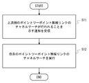
- FIG. 3 is a flowchart showing a control procedure performed by the controller 104.
- the controller 104 receives a notification indicating that a channel search for the upstream point-to-point wireless link is performed.
- the controller 104 performs a channel search for its own point-to-point radio link in step S12.
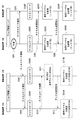
- FIG. 4 is a sequence diagram showing an example of a control procedure including channel search and use radio channel change in the mobile backhaul 1000.
- the point-to-point wireless device 10E detects a decrease in reception quality of the forward link 12E.
- the procedure of changing the used radio channel is typically performed in order to avoid interference that a specific radio channel receives from other radio systems. Therefore, the reception quality monitored in step S101 to trigger the change procedure of the used radio channel may typically be SignalSigntoInterference plus Noise Ratio (SINR).
- SINR SignalSigntoInterference plus Noise Ratio
- SINR SignalSigntoInterference plus Noise Ratio
- the received signal strength (Received Signal Strength Indicator (RSSI)) is also used to distinguish it from deterioration of the forward link 12E due to worsening weather conditions or shielding by some structure. May be used.
- RSSI Receiveived Signal Strength Indicator
- step S102 in response to detecting the deterioration of the reception quality of the forward link 12E, the wireless device 10E sends a predetermined notification to the wireless device 10F using the currently used wireless channel of the reverse link 13E.
- the predetermined notification in step S102 may indicate that the channel search of the forward link 12E is performed in the wireless device 10E (channel search notification).
- the predetermined notification in step S102 may indicate that a failure has been detected in the forward link 12E, or a request for performing a channel search for the reverse link 13E to the radio apparatus 10F. May be indicated.
- step S103 the wireless device 10E transmits a predetermined notification to the wireless device 10B configuring the downstream point-to-point wireless system 1A.
- the predetermined notification in step S103 may also indicate that a channel search for the forward link 12E is performed (channel search notification).
- the predetermined notification in step S103 may indicate that a failure has been detected in the forward link 12E, or perform a channel search for the downstream point-to-point wireless link 11A. A request may be indicated.
- the wireless device 10B transmits a channel search notification to the wireless device 10A in order to start the channel search of the forward link 12A by the wireless device 10A (step S104).
- step S105A the wireless device 10A performs a channel search for the forward link 12A.
- step S105E the wireless device 10E performs a channel search for the forward link 12E. Note that the channel search in step S105A does not have to be performed completely in synchronization with the channel search in step S105E.
- the channel search in step S105A is preferably performed within the stop period of forward link 12E including the channel search in step S105E.
- step S106 the radio apparatus 10E determines a new radio channel to be used as the radio channel used for the forward link 12E based on the channel search result in step S105E. Then, the wireless device 10E transmits a channel change instruction to the wireless device 10F using the reverse link 13E. The channel change instruction indicates a new radio channel to be used for the forward link 12E determined by the radio device 10E.
- both the radio devices 10E and 10F change the radio channel used by the forward link 12E to the new radio channel determined in step S106.
- the operation in step S107E may be started in response to the transmission of the change instruction in step S106 or in response to the elapse of a predetermined standby time from the transmission of the change instruction.
- the operation in step S107F may be started in response to the reception of the change instruction in step S106 or in response to the elapse of a predetermined standby time from the reception of the change instruction.
- the forward link 12E returns to a usable state.
- Steps S108, S109A, and S109B show a procedure for changing the radio channel used by the forward link 12A in the point-to-point radio system 1A on the downstream side.
- This change procedure may be performed similarly to the procedure (steps S106, S107E, and S107F) in the upstream point-to-point wireless system 1E.
- steps S108, S109A, and S109B are not necessarily required.
- the channel search result in the downstream point-to-point wireless system 1A is held in the point-to-point wireless system 1A for use in the event of a failure in the future forward link 12A, for example. It may also be transmitted to an OAM system not shown.
- FIG. 4 shows a procedure for switching only the used radio channel of the forward link (forward link 12E), but the used radio channels of the forward link 12E and the reverse link 13E may be switched simultaneously.
- FIG. 5 is a sequence diagram illustrating an example of a control procedure including a channel search and a change of a used radio channel.
- the channel search and the used radio channel change are modified so as to be performed on the bidirectional radio link.
- step S205A the wireless device 10A performs a channel search for the forward link 12A.
- step S205B the wireless device 10B performs a channel search for the reverse link 13A.
- step S205E the wireless device 10E performs a channel search for the forward link 12E.
- step S205F the wireless device 10F performs a channel search for the reverse link 13E.
- steps S206, S207E, and S207F in FIG. 5 is the same as the processing in steps S106, S107E, and S107F in FIG. 4, description thereof is omitted here.
- Steps S208, S209E, and S209F show a procedure for changing the radio channel used by the reverse link 13E in the upstream point-to-point radio system 1E.
- Steps S208, S209E, and S209F may be performed when a radio channel with better reception quality than the currently used radio channel of the reverse link 13E is found in the channel search of step S205F. That is, in step S208, the radio apparatus 10F determines a new radio channel to be used as a radio channel to be used for the reverse link 13E based on the channel search result in step S205F. And the radio
- the channel change instruction indicates a new use radio channel of the reverse link 13E determined in the radio apparatus 10F.
- steps S209E and S209F both of the wireless devices 10E and 10F change the used wireless channel of the reverse link 13E to the new used wireless channel determined in step S208.
- Steps S210 to S212, 213A, and S213B show a procedure for changing the radio channels used by the forward link 12A and the reverse link 13A in the downstream point-to-point radio system 1A.
- radio apparatus 10A transmits the result of channel search (step S205A) of forward link 12A to radio apparatus 10B.
- the radio apparatus 10B determines new radio channels to be used for the forward link 12A and the reverse link 13A based on the results of channel search (steps S205A and S205B) for the forward link 12A and the reverse link 13A. To do.
- step S212 the wireless device 10B transmits a channel change instruction to the wireless device 10A.
- This channel change instruction indicates the new radio channel used by the links 12A and 13A determined in step S211.
- steps S213A and S213B both the radio devices 10A and 10B change the used radio channel of the forward link 12A and the reverse link 13A to the new radio channel determined in step S211.
- the change procedure of steps S210 to S212, 213A, and S213B is a procedure in which one radio apparatus 10B determines a bidirectional use radio channel. However, this point may be changed as appropriate.
- the radio device 10A may determine the radio channel used for the forward link 12A
- the radio device 10B may determine the radio channel used for the reverse forward link 13A.
- the changing procedure of steps S210 to S212 and S213A and S213B may not be performed.
- FIG. 6 is a sequence diagram showing an example of a control procedure including a channel search and a change in used radio channel.
- the radio channels used by the point-to-point wireless systems 1A and 1E are determined.
- step S306 the wireless device 10A transmits the result of the channel search (step S305A) of the forward link 12A to the wireless device 10B.
- step S307 the wireless device 10B transfers the received channel search result of the forward link 12A (step S305A) to the wireless device 10E.
- step S308 the wireless device 10E uses both the channel search result of the forward link 12A by the wireless device 10A and the channel search result of the forward link 12E by itself (the wireless device 10E) to use the forward links 12A and 12E.
- the wireless channel to be used is determined.
- the radio apparatus 10E may determine the radio channels used so that different radio channels (radio frequency carriers) are used in the forward links 12A and 12E. Thereby, it is possible to prevent the forward links 12A and 12E from interfering with each other.
- the wireless device 10E may select the forward link 12A and the forward link 12A from the available wireless channels (clear channel or unoccupied channel) that have obtained good reception quality in the two channel searches of the forward links 12A and 12E.
- the radio channel used for each of 12E may be determined.
- the wireless device 10E is a product set (common part, intersection) of the free wireless channel set obtained by the channel search of the forward link 12A and the free wireless channel set obtained by the channel search of the forward link 12E. From among them, the radio channel used for each of the forward links 12A and 12E may be determined.
- the nearby point-to-point wireless system 1A may also be susceptible to interference in that wireless channel. According to the example shown here, it is possible to exclude radio channels that may cause such interference from selection.
- the wireless device 10E transmits a channel change instruction to the wireless device 10F.
- This channel change instruction indicates the new radio channel used for the forward link 12E determined in step S308.
- both the radio devices 10E and 10F change the radio channel used by the forward link 12E to the new radio channel determined in step S308.
- step S311 the wireless device 10E transmits a channel change instruction to the wireless device 10B.
- This channel change instruction indicates a new radio channel to be used for the forward link 12A determined in step S308.
- the radio apparatus 10B transfers the channel change instruction received from the radio apparatus 10E to the radio apparatus 10A.
- steps S313A and S313B both the radio devices 10A and 10B change the radio channel used by the forward link 12A to the new radio channel determined in step S308.
- the procedure in FIG. 6 is only an example.
- the subject that determines the radio channels used for the forward links 12A and 12E may be other radio devices, for example, the radio devices 10A or 10B, instead of the radio device 10F.
- the subject that determines the radio channels used for the forward links 12A and 12E may be an OAM system (not shown).
- the radio apparatuses 10A and 10E may transmit the channel search result of the forward link 12A and the channel search result of the forward link 12E to the OAM system, respectively.
- the first to third embodiments described above may be implemented in combination as appropriate.
- the second and third embodiments may be combined.
- the radio channels used by the reverse links 13A and 13E are determined using both the channel search result of the reverse link 13A by the radio device 10B and the channel search result of the reverse link 13E by the radio device 10F. Also good.
- the processing related to channel search and use radio channel change performed by the above-described radio apparatuses 10A, 10B, 10C, 10D, 10E, and 10F may be realized using a semiconductor processing apparatus including Application Specific Integrated Circuit (ASIC). .
- ASIC Application Specific Integrated Circuit
- These processes may be realized by causing a computer including at least one processor (e.g. microprocessor, Micro Processing Unit (MPU), Central Processing Unit (CPU)) to execute a program.
- MPU Micro Processing Unit
- CPU Central Processing Unit
- Non-transitory computer readable media include various types of tangible storage media (tangible storage medium). Examples of non-transitory computer-readable media are magnetic recording media (eg flexible disks, magnetic tapes, hard disk drives), magneto-optical recording media (eg magneto-optical discs), CompactComp Disc Read Only Memory (CD-ROM), CD-ROM Includes R, CD-R / W, semiconductor memory (eg mask ROM, Programmable ROM (PROM), Erasable PROM (EPROM), flash ROM, Random Access Memory (RAM)).
- the program may also be supplied to the computer by various types of temporary computer-readable media. Examples of transitory computer readable media include electrical signals, optical signals, and electromagnetic waves.
- the temporary computer-readable medium can supply the program to the computer via a wired communication path such as an electric wire and an optical fiber, or a wireless communication path.
Landscapes
- Engineering & Computer Science (AREA)
- Signal Processing (AREA)
- Computer Networks & Wireless Communication (AREA)
- Mobile Radio Communication Systems (AREA)
Priority Applications (5)
| Application Number | Priority Date | Filing Date | Title |
|---|---|---|---|
| EP15765382.5A EP3122101B1 (en) | 2014-03-18 | 2015-02-18 | Point-to-point wireless device, mobile backhaul system, and communication control method |
| US15/121,473 US10123305B2 (en) | 2014-03-18 | 2015-02-18 | Point-to-point radio apparatus, mobile backhaul system, and communication control method |
| CN201580014473.XA CN106105297A (zh) | 2014-03-18 | 2015-02-18 | 点对点无线电设备、移动回程系统和通信控制方法 |
| US16/150,924 US10798681B2 (en) | 2014-03-18 | 2018-10-03 | Point-to-point radio apparatus, mobile backhaul system, and communication control method |
| US17/018,053 US11350386B2 (en) | 2014-03-18 | 2020-09-11 | Point-to-point radio apparatus, mobile backhaul system, and communication control method |
Applications Claiming Priority (2)
| Application Number | Priority Date | Filing Date | Title |
|---|---|---|---|
| JP2014-054547 | 2014-03-18 | ||
| JP2014054547A JP2015177497A (ja) | 2014-03-18 | 2014-03-18 | ポイントツーポイント無線装置、モバイルバックホールシステム、通信制御方法、及びプログラム |
Related Child Applications (2)
| Application Number | Title | Priority Date | Filing Date |
|---|---|---|---|
| US15/121,473 A-371-Of-International US10123305B2 (en) | 2014-03-18 | 2015-02-18 | Point-to-point radio apparatus, mobile backhaul system, and communication control method |
| US16/150,924 Continuation US10798681B2 (en) | 2014-03-18 | 2018-10-03 | Point-to-point radio apparatus, mobile backhaul system, and communication control method |
Publications (1)
| Publication Number | Publication Date |
|---|---|
| WO2015141125A1 true WO2015141125A1 (ja) | 2015-09-24 |
Family
ID=54144117
Family Applications (1)
| Application Number | Title | Priority Date | Filing Date |
|---|---|---|---|
| PCT/JP2015/000736 WO2015141125A1 (ja) | 2014-03-18 | 2015-02-18 | ポイントツーポイント無線装置、モバイルバックホールシステム、及び通信制御方法 |
Country Status (5)
| Country | Link |
|---|---|
| US (3) | US10123305B2 (zh) |
| EP (1) | EP3122101B1 (zh) |
| JP (1) | JP2015177497A (zh) |
| CN (1) | CN106105297A (zh) |
| WO (1) | WO2015141125A1 (zh) |
Families Citing this family (1)
| Publication number | Priority date | Publication date | Assignee | Title |
|---|---|---|---|---|
| CN110636628B (zh) | 2018-06-21 | 2023-06-16 | 中兴通讯股份有限公司 | 信息传输方法及装置 |
Citations (4)
| Publication number | Priority date | Publication date | Assignee | Title |
|---|---|---|---|---|
| WO2009014764A1 (en) * | 2007-07-25 | 2009-01-29 | Teenay Wireless, Inc. | A multi-tier backhaul network system with traffic differentiation and advanced processing capabilities and methods therefor |
| JP2011205638A (ja) * | 2010-03-25 | 2011-10-13 | Toshiba Corp | フェムトセルにおける自動障害報告 |
| JP2013021648A (ja) * | 2011-07-14 | 2013-01-31 | Nippon Telegr & Teleph Corp <Ntt> | 無線中継装置および無線中継方法 |
| JP2013102361A (ja) * | 2011-11-09 | 2013-05-23 | Hitachi Ltd | 移動体通信システム、迂回経路構築方法およびセンタ監視装置 |
Family Cites Families (26)
| Publication number | Priority date | Publication date | Assignee | Title |
|---|---|---|---|---|
| DE59712576D1 (de) * | 1996-11-22 | 2006-04-20 | Siemens Ag | Verfahren und routing-system zur dynamischen verkehrslenkung in einem kommunikationsnetz |
| ES2279463T3 (es) | 2001-10-12 | 2007-08-16 | Nokia Corporation | Sistema de radiocomunicaciones de microondas de punto a punto. |
| ATE554579T1 (de) * | 2005-09-21 | 2012-05-15 | Lg Electronics Inc | Einrichtung zusätzlicher rückwärtsverbindungsträger in einem drahtlosen mehrträgersystem |
| US7688835B2 (en) * | 2006-03-15 | 2010-03-30 | Motorola, Inc. | Dynamic wireless backhaul |
| US20070218910A1 (en) * | 2006-03-15 | 2007-09-20 | Motorola, Inc. | Dynamic beam steering of backhaul traffic |
| EP2464188A1 (en) | 2006-08-31 | 2012-06-13 | LG Electronics, Inc. | Method of changing channels and configuring a sub-network in a wireless network |
| US8718561B2 (en) * | 2007-11-20 | 2014-05-06 | Aruba Networks, Inc. | Method and apparatus for detecting and avoiding interference in a communications network |
| US8861332B2 (en) * | 2010-02-11 | 2014-10-14 | Lg Electronics Inc. | Method and apparatus of recovering backhaul link failure between base station and relay node |
| US8948085B2 (en) * | 2010-03-17 | 2015-02-03 | Qualcomm Incorporated | Methods and apparatus for best-effort radio backhaul among cells on unlicensed or shared spectrum |
| JP5451521B2 (ja) | 2010-05-18 | 2014-03-26 | 日本電気株式会社 | データ通信システム、データ通信装置、データ通信装置の制御方法、プログラム及び記録媒体 |
| US8744506B2 (en) * | 2010-06-17 | 2014-06-03 | Qualcomm Incorporated | Device discovery on white space frequencies |
| CN102300270B (zh) * | 2010-06-25 | 2015-01-14 | 电信科学技术研究院 | 回程链路控制信道信息的资源配置方法和设备 |
| US8305966B2 (en) * | 2010-06-29 | 2012-11-06 | Intel Corporation | Femto backhaul fault detection and recovery |
| US9749880B2 (en) * | 2010-06-30 | 2017-08-29 | Verizon Patent And Licensing Inc. | Base station failover using neighboring base stations as relays |
| US8824311B2 (en) * | 2010-09-13 | 2014-09-02 | Blinq Wireless Inc. | System and method for co-channel interference measurement and managed adaptive resource allocation for wireless backhaul |
| EP2866514A3 (en) | 2010-11-16 | 2015-05-20 | Interdigital Patent Holdings, Inc. | Method and apparatus for wireless direct link operation |
| US20120224472A1 (en) * | 2011-03-04 | 2012-09-06 | Electronics And Telecommunications Research Institute | Method for relaying of base station, method for relaying of terminal and method for transmitting |
| US8804502B2 (en) * | 2011-06-28 | 2014-08-12 | At&T Mobility Ii Llc | Emergency backhaul links for wireless telecommunications networks |
| US8989762B1 (en) * | 2013-12-05 | 2015-03-24 | CBF Networks, Inc. | Advanced backhaul services |
| US8502733B1 (en) * | 2012-02-10 | 2013-08-06 | CBF Networks, Inc. | Transmit co-channel spectrum sharing |
| US9565684B2 (en) | 2012-04-23 | 2017-02-07 | Intel Corporation | Systems and methods for avoiding interference for a peer-to-peer network connection |
| TW201427447A (zh) * | 2012-09-17 | 2014-07-01 | Interdigital Patent Holdings | 回載無線電資源及小胞元回載延遲估計自我最佳化 |
| US9078157B2 (en) * | 2012-12-31 | 2015-07-07 | Verizon Patent And Licensing Inc. | Quick recovery of RF sessions after backhaul link failure |
| US10021600B2 (en) * | 2013-01-02 | 2018-07-10 | Qualcomm Incorporated | Backhaul traffic reliability in unlicensed bands using spectrum sensing and channel reservation |
| KR20140088375A (ko) * | 2013-01-02 | 2014-07-10 | 삼성전자주식회사 | 무선 통신 시스템에서 기지국 간 무선 링크 복구를 위한 방법 및 장치 |
| US10554482B2 (en) * | 2016-03-18 | 2020-02-04 | Plume Design, Inc. | Optimization of distributed Wi-Fi networks estimation and learning |
-
2014
- 2014-03-18 JP JP2014054547A patent/JP2015177497A/ja not_active Abandoned
-
2015
- 2015-02-18 CN CN201580014473.XA patent/CN106105297A/zh active Pending
- 2015-02-18 WO PCT/JP2015/000736 patent/WO2015141125A1/ja active Application Filing
- 2015-02-18 US US15/121,473 patent/US10123305B2/en active Active
- 2015-02-18 EP EP15765382.5A patent/EP3122101B1/en active Active
-
2018
- 2018-10-03 US US16/150,924 patent/US10798681B2/en active Active
-
2020
- 2020-09-11 US US17/018,053 patent/US11350386B2/en active Active
Patent Citations (4)
| Publication number | Priority date | Publication date | Assignee | Title |
|---|---|---|---|---|
| WO2009014764A1 (en) * | 2007-07-25 | 2009-01-29 | Teenay Wireless, Inc. | A multi-tier backhaul network system with traffic differentiation and advanced processing capabilities and methods therefor |
| JP2011205638A (ja) * | 2010-03-25 | 2011-10-13 | Toshiba Corp | フェムトセルにおける自動障害報告 |
| JP2013021648A (ja) * | 2011-07-14 | 2013-01-31 | Nippon Telegr & Teleph Corp <Ntt> | 無線中継装置および無線中継方法 |
| JP2013102361A (ja) * | 2011-11-09 | 2013-05-23 | Hitachi Ltd | 移動体通信システム、迂回経路構築方法およびセンタ監視装置 |
Also Published As
| Publication number | Publication date |
|---|---|
| US10798681B2 (en) | 2020-10-06 |
| US20170006579A1 (en) | 2017-01-05 |
| CN106105297A (zh) | 2016-11-09 |
| US20190037536A1 (en) | 2019-01-31 |
| US11350386B2 (en) | 2022-05-31 |
| EP3122101B1 (en) | 2020-12-23 |
| EP3122101A1 (en) | 2017-01-25 |
| JP2015177497A (ja) | 2015-10-05 |
| EP3122101A4 (en) | 2017-11-08 |
| US20200413375A1 (en) | 2020-12-31 |
| US10123305B2 (en) | 2018-11-06 |
Similar Documents
| Publication | Publication Date | Title |
|---|---|---|
| JP6870856B2 (ja) | 二重接続における無線リンク障害ハンドリング | |
| CN112689974B (zh) | 无线接入网中的路由选择和服务质量支持 | |
| JP6451783B2 (ja) | 第1の基地局及びその方法 | |
| JP5795809B2 (ja) | バックホール選択をサポートする方法及び装置 | |
| US9130834B2 (en) | Method and device for monitoring backbone inter base-station communication | |
| CN112368988A (zh) | 在集成接入及回程系统中进行动态路由选择 | |
| EP3028501B1 (en) | Methods and apparatus for dual connectivity | |
| KR20210141696A (ko) | 링크상태 통지 방법 및 장치, 링크 처리 방법 및 장치, 저장매체, 전자장치 | |
| CN110612730A (zh) | 释放小区组的信令无线电承载 | |
| CN112534874A (zh) | 用于处置链路转换的第一网络节点、无线装置以及由此执行的方法 | |
| US8954057B2 (en) | Base station, detection device, communication system and detection method | |
| EP3586561B1 (en) | Method and devices for dual connectivity between a dual protocol stack user equipment and two baseband units of a radio access telecommunications network | |
| US20230269653A1 (en) | Rerouting method and apparatus, and communication device | |
| US11350386B2 (en) | Point-to-point radio apparatus, mobile backhaul system, and communication control method | |
| WO2010123121A1 (ja) | 無線基地局及びコネクション確立制御方法 | |
| CN116349303A (zh) | 用于分组重路由的方法及装置 | |
| JP6423514B2 (ja) | 構成方法、ネットワークデバイス、およびユーザ機器 | |
| EP4224902A1 (en) | Communication control method | |
| EP3888305A1 (en) | Differential latency measurement | |
| WO2023026681A1 (ja) | 中継装置、制御方法、プログラム、及び通信システム | |
| US20230337085A1 (en) | Communication apparatus, control method of communication apparatus, and computer-readable storage medium |
Legal Events
| Date | Code | Title | Description |
|---|---|---|---|
| 121 | Ep: the epo has been informed by wipo that ep was designated in this application |
Ref document number: 15765382 Country of ref document: EP Kind code of ref document: A1 |
|
| WWE | Wipo information: entry into national phase |
Ref document number: 15121473 Country of ref document: US |
|
| NENP | Non-entry into the national phase |
Ref country code: DE |
|
| REEP | Request for entry into the european phase |
Ref document number: 2015765382 Country of ref document: EP |
|
| WWE | Wipo information: entry into national phase |
Ref document number: 2015765382 Country of ref document: EP |