WO2015141019A1 - 機器制御装置、機器制御システム、機器制御方法、および機器制御プログラム - Google Patents
機器制御装置、機器制御システム、機器制御方法、および機器制御プログラム Download PDFInfo
- Publication number
- WO2015141019A1 WO2015141019A1 PCT/JP2014/066374 JP2014066374W WO2015141019A1 WO 2015141019 A1 WO2015141019 A1 WO 2015141019A1 JP 2014066374 W JP2014066374 W JP 2014066374W WO 2015141019 A1 WO2015141019 A1 WO 2015141019A1
- Authority
- WO
- WIPO (PCT)
- Prior art keywords
- information
- control
- control information
- type
- designation
- Prior art date
- Legal status (The legal status is an assumption and is not a legal conclusion. Google has not performed a legal analysis and makes no representation as to the accuracy of the status listed.)
- Ceased
Links
Images



Classifications
-
- H—ELECTRICITY
- H04—ELECTRIC COMMUNICATION TECHNIQUE
- H04Q—SELECTING
- H04Q9/00—Arrangements in telecontrol or telemetry systems for selectively calling a substation from a main station, in which substation desired apparatus is selected for applying a control signal thereto or for obtaining measured values therefrom
-
- H—ELECTRICITY
- H04—ELECTRIC COMMUNICATION TECHNIQUE
- H04Q—SELECTING
- H04Q2209/00—Arrangements in telecontrol or telemetry systems
- H04Q2209/60—Arrangements in telecontrol or telemetry systems for transmitting utility meters data, i.e. transmission of data from the reader of the utility meter
Definitions
- the present invention relates to a device control device, a device control system, a device control method, and a device control program, and more particularly to a device control device, a device control system, a device control method, and a device control program that perform protocol conversion.
- a communication protocol for energy management systems such as smart houses, is being developed.
- SEP2 Smart Energy Profile 2, Smart Energy Profile 2 Application Protocol Standard
- ZigBee Alliance, Inc. and HomePlug.
- unnecessary energy consumption in the home can be suppressed by controlling the operation contents of the devices such as air conditioning and lighting by the smart meter installed in the home.
- an electric power company issues a demand response (Demand Response) to an electric power consumer when power supply and demand are expected to be tight.
- a demand response is issued by an electric power company
- the smart meter in the home creates control information for controlling the operation content of the device according to SEP2 and transmits it to each device.
- each device When each device is compatible with SEP2, each device changes its own operation content according to the control information received from the smart meter, for example, to suppress power consumption.
- the type of device that is controlled by the control information according to SEP2 is partially different from the type of device that is controlled by the control information according to SEP1.
- the present invention has been made to solve the above-described problems, and an object of the present invention is to provide a device control apparatus and device capable of favorably controlling devices by appropriately converting control information according to different protocols.
- a control system, a device control method, and a device control program are provided.
- an apparatus control device that controls a plurality of devices, and acquires route information related to a power supply route to each of the devices.
- a transmission unit that transmits the second control information to the device, wherein the first control information includes first designation information that designates a type of device to be controlled, and the second control information
- the control information includes second designation information that designates the type of device to be controlled, and the second designation information can designate a number of device types different from the first designation information, and the protocol
- the conversion unit converts the route information into Zui and associates the type of the first said device designated in the designation information of the type of the device specified in the second specifying information.
- a device control system is a device that controls a plurality of devices using a smart meter and other control information created from control information received from the smart meter.
- a device control system including a control device, wherein the device control device includes a route information acquisition unit that acquires route information related to a power supply route to each device, and first control information according to a first communication protocol.
- a control information acquisition unit to acquire; a protocol conversion unit that converts the first control information into second control information according to a second communication protocol; and a transmission unit that transmits the second control information to the device.
- the first control information includes first designation information for designating a type of a device to be controlled, and the second control information is second for designating a type of the device to be controlled.
- the second designation information can designate a number of types of devices different from the first designation information, and the protocol conversion unit can determine the first designation based on the route information.
- the device type designated in the information is associated with the device type designated in the second designation information.
- a device control method for controlling a plurality of devices, and acquires route information regarding a power supply route to each of the devices.
- Transmitting the information to the device wherein the first control information includes first designation information for designating a type of the device to be controlled, and the second control information is for the device to be controlled.
- a second designation information for designating a type wherein the second designation information can designate a number of types of devices different from the first designation information, and the first control information is designated as the second control information.
- Step to convert to control information Oite based on the route information, associates the type of the first said device designated in the designation information of the type of the device specified in the second specifying information.
- an apparatus control program for controlling a plurality of apparatuses, and includes route information regarding a power supply path to each of the apparatuses. Obtaining first control information according to a first communication protocol, converting the first control information into second control information according to a second communication protocol, and And transmitting the control information to the device.
- the first control information includes first designation information for designating a type of device to be controlled, and the second control information.
- the control information includes second designation information that designates the type of the device to be controlled, and the second designation information can designate a different number of device types from the first designation information,
- the type of the device designated in the first designation information is designated in the second designation information based on the route information.
- the program is associated with the type of the device to be executed.
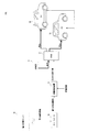
- FIG. 1 is a diagram showing a configuration of a device control system according to an embodiment of the present invention.
- FIG. 2 is a diagram illustrating an example of a state in which the device control system according to the embodiment of the present invention includes EVSE and EV as devices.
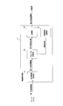
- FIG. 3 is a diagram showing a configuration of the device control apparatus according to the embodiment of the present invention.
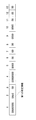
- FIG. 4 is a diagram showing an example of a format of first control information in the device control system according to the embodiment of the present invention.
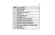
- FIG. 5 is a diagram showing the names of the fields in the control information format shown in FIG.
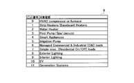
- FIG. 6 is a diagram illustrating a correspondence relationship between the content of the first designation information illustrated in FIG. 4 and the target type.
- FIG. 7 is a diagram showing an example of the content of the second control information in the device control system according to the embodiment of the present invention.
- FIG. 8 is a diagram illustrating a correspondence relationship between the content of the second designation information and the target type in the device control system according to the embodiment of the present invention.
- FIG. 9 is a flowchart that defines an example of an operation procedure when the device control apparatus converts the first control information into the second control information in the device control system according to the embodiment of the present invention.
- a device control device is a device control device that controls a plurality of devices, and includes a route information acquisition unit that acquires route information regarding a power supply route to each of the devices, A control information acquisition unit that acquires first control information according to a first communication protocol, a protocol conversion unit that converts the first control information into second control information according to a second communication protocol, and the second A transmission unit that transmits control information to the device, wherein the first control information includes first designation information that designates a type of a device to be controlled, and the second control information includes a control target Including second designation information for designating a type of device, wherein the second designation information can designate a number of types of devices different from the first designation information, and the protocol conversion unit is configured to provide the route information Based on the first designation information Associating the type of said designated device type of the device specified in the second specifying information in.
- the protocol conversion unit can be designated when a plurality of types of the device corresponding to the type of the device designated in the first designation information can be designated in the second designation information.
- the second designation information that designates the type of the upstream device in the power supply path among the plurality of types of the device is created.
- the power consumption of the downstream device can be controlled by controlling the upstream device.
- a device control system includes a device control that includes a smart meter and a device control device that controls a plurality of devices with different control information created from control information received from the smart meter.
- the device control apparatus includes a route information acquisition unit that acquires route information regarding a power supply route to each device, a control information acquisition unit that acquires first control information according to a first communication protocol, and A protocol conversion unit that converts the first control information into second control information according to a second communication protocol, and a transmission unit that transmits the second control information to the device.
- the control information includes first designation information that designates the type of the device to be controlled, and the second control information includes second designation information that designates the type of the device to be controlled.
- the fixed information can specify a number of device types different from the first specified information
- the protocol conversion unit can specify the device type specified in the first specified information based on the route information. Is associated with the type of the device designated in the second designation information.
- a device control method is a device control method for controlling a plurality of devices, the step of acquiring route information regarding a power supply route to each of the devices, and a first communication Obtaining first control information in accordance with a protocol; converting the first control information into second control information in accordance with a second communication protocol; and transmitting the second control information to the device.
- the first control information includes first designation information for designating a type of device to be controlled, and the second control information is a second designation for designating the type of device to be controlled.
- the second specification information can specify a number of types of devices different from the first specification information.
- the route information Zui and associates the type of the first said device designated in the designation information of the type of the device specified in the second specifying information.
- the device control program is a device control program for controlling a plurality of devices, and obtains route information regarding a power supply route to each of the devices in a computer, Obtaining first control information according to a first communication protocol, converting the first control information into second control information according to a second communication protocol, and converting the second control information into the device.
- the first control information includes first designation information for designating a type of a device to be controlled, and the second control information is for a control target.
- the second designation information includes a second designation information for designating a type of the device, and the second designation information can designate a number of types of the device different from the first designation information, and the first control information is designated as the first control information.
- a program that associates the type of the device designated in the first designation information with the type of the device designated in the second designation information based on the route information. is there.
- FIG. 1 is a diagram showing a configuration of a device control system according to an embodiment of the present invention.
- the device control system 101 includes a power management server 10, a device control device 11, a plurality of devices 12, and a smart meter 15.
- the device control system 101 is, for example, a HEMS (Home Energy Management System).
- the power management server 10 is installed in an electric power company, for example, and transmits power management information to the smart meter 15 via the Internet.
- the power management information is information transmitted to the smart meter 15 when the power company issues a demand response, for example, information indicating that the power supply is tight, electric charge information by day or time zone, Or it is the information etc. which show the power-saving request
- the device control device 11, the device 12, and the smart meter 15 are installed in the house 5, for example.
- the device control device 11 and the smart meter 15 are connected to each other by wire or wirelessly.
- the device control device 11 and the device 12 are connected to each other by wire or wirelessly.
- the smart meter 15 corresponds to SEP1 which is a first communication protocol, receives power management information from the power management server 10, and is control information according to the first communication protocol based on the received power management information. First control information is created. Then, the smart meter 15 transmits the created first control information to the device control apparatus 11.
- the control information is information for controlling the operation of the device 12, specifies the type of device to be controlled, and includes control contents. Specifically, the control information includes designation information that designates the type of device to be controlled, period instruction information that indicates a control period, operation instruction information that indicates operation contents, and the like.
- the type of control target device specified in the specification information is also referred to as a target type.
- the device control apparatus 11 performs protocol conversion on the first control information received from the smart meter 15 and controls each device 12 by transmitting the second control information after the protocol conversion to each device 12. Specifically, the device control apparatus 11 converts the first control information received from the smart meter 15 into second control information according to SEP2 that is the second communication protocol, and transmits the second control information to each device 12. The device control apparatus 11 may manage the operation and power consumption of each device 12.
- the device 12 is a device such as an air conditioner, an illuminator, an electric vehicle charging facility (EVSE), an electric vehicle (EV), or an electric vehicle (EV), and corresponds to SEP2. That is, the device 12 is controlled by the second control information that is control information according to SEP2.
- EVSE electric vehicle charging facility
- EV electric vehicle
- EV electric vehicle
- EV electric vehicle
- EV electric vehicle
- the device 12 receives the second control information from the device control apparatus 11, and confirms the target type specified by the received control information. Then, when the specified target type matches the own type, the device 12 changes its own operation content based on the content of the control information.
- the control information received by the indoor illuminator specifies “interior illuminator” as the target type, and darkens the illumination after 9 am
- the room illuminator dims its own illumination after 9 am according to the content of the received control information.
- FIG. 2 is a diagram illustrating an example of a state in which the device control system according to the embodiment of the present invention includes EVSE and EV as devices.
- device control system 101 includes EVSE 17 and a plurality of EVs 18 as device 12.
- the device control apparatus 11 converts the first control information received from the smart meter 15 into the second control information and transmits the second control information to each device 12, here, the EVSE 17 and each EV 18.
- EVSE 17 receives power supply from distribution board 14. Further, when the second control information received from the device control apparatus 11 specifies “EVSE” as the target type, the EVSE 17 operates according to the content of the control information.
- the received second control information includes content instructing to suppress the output power of “EVSE” by 20% from the normal time
- the total power supplied to the EV 18 is calculated. It operates to suppress 20% from the normal time.
- Each EV 18 receives power supply from the EVSE 17. That is, each EV 18 exists on the downstream side of the EVSE 17 in the power supply path from the distribution board 14.
- each EV 18 operates according to the content of the control information when the second control information received from the device control apparatus 11 designates “EV” as the target type.
- the EV 18 when the received second control information includes content instructing to reduce the power consumption of “EV” by 20% from the normal time, for example, the EV 18 It operates so as to suppress the power used for charging by 20% from the normal time.
- Each EV 18 is not limited to the configuration that receives the second control information directly from the device control apparatus 11, but may be configured to receive the EV control 17 via the EVSE 17.
- the second control information can specify a larger number of target types than the first control information.
- the designation information included in the second control information (hereinafter also referred to as second designation information) is more than the designation information included in the first control information (hereinafter also referred to as first designation information).
- first designation information is more than the designation information included in the first control information.
- the first designation information can designate “EV”, but cannot designate “EVSE”.
- the second designation information can designate both “EV” and “EVSE”.
- the device control apparatus 11 converts the first control information into the second control information
- the device type designated in the first designation information is changed to the device type designated in the second designation information. Associate with.
- the process of associating the device type designated in the first designation information with the device type designated in the second designation information is also referred to as an association process.
- the content of the association process appropriate for the device control system 101 may vary depending on the type or connection relationship of each device 12. Therefore, for example, the user operates the device control device 11 to input route information that is information regarding the power supply route to the device 12 to the device control device 11. And the apparatus control apparatus 11 performs a matching process based on the acquired path information, when converting 1st control information into 2nd control information.
- the route information is, for example, information indicating that the device control system 101 includes one EVSE 17 and two EVs 18 as the devices 12, information indicating that the EVSE 17 exists on the upstream side of the power supply route to the EV 18, And information indicating that the power supplied to each EV 18 can be changed by controlling the EVSE 17.
- FIG. 3 is a diagram showing a configuration of the device control apparatus according to the embodiment of the present invention.
- device control apparatus 11 includes a control information acquisition unit 51, a protocol conversion unit 52, a transmission unit 53, and a route information acquisition unit 54.
- the route information acquisition unit 54 acquires the route information input by the user to the device control apparatus 11 and sends the acquired route information to the protocol conversion unit 52.
- the route information acquisition unit 54 is not limited to the configuration for acquiring the route information input by the user, and may be configured to acquire the route information by communicating with the device 12, for example.
- the control information acquisition unit 51 acquires the first control information from the smart meter 15 and sends the acquired first control information to the protocol conversion unit 52.
- the second designation information can designate a plurality of device types corresponding to the device type designated in the first designation information.
- the device control apparatus 11 when the device control apparatus 11 acquires the first control information including an instruction to suppress the power consumption of “EV”, the device control apparatus 11 controls the EVSE 17 to reduce the power supplied to the EV 18, The EV 18 is controlled to reduce the charging power of each EV 18 or both.
- the protocol conversion unit 52 of the device control apparatus 11 associates “EV” designated in the first designation information with one or both of “EVSE” and “EV” in the second designation information. Can do.
- the protocol conversion unit 52 specifies the type of the upstream device 12 in the power supply path to the device 12 among the plurality of types of devices 12 that can be specified in the second specification information. Second designation information to be created is created.
- the protocol conversion unit 52 recognizes that the EVSE 17 exists on the upstream side of the EVSE 17 and the EV 18 based on the route information received from the route information acquisition unit 54.
- the protocol conversion unit 52 When the protocol conversion unit 52 receives the first control information with “EV” as the target type, that is, when receiving the designation information designating “EV”, the protocol conversion unit 52 selects “EVSE” which is the type of EVSE17. 2nd designation information which designates "is created. Then, the protocol converter 52 creates second control information including the second designation information and sends it to the transmitter 53.
- the transmission unit 53 transmits the second control information received from the protocol conversion unit 52 to each device 12.
- the EVSE 17 is not limited to a configuration connected to a plurality of EVs 18 and may be configured to be connected to one EV 18.
- FIG. 4 is a diagram showing an example of a format of first control information in the device control system according to the embodiment of the present invention.
- each field is numbered from 1 to 13.
- the field of number 2 represents the first designation information.
- “06b0”, which is the content of the first designation information, indicates the target type.
- the content of the first designation information is expressed in hexadecimal.
- FIG. 5 is a diagram showing the names of the fields in the control information format shown in FIG.
- table A shows the names of the fields from number 1 to number 13 shown in FIG.
- the name of the field of number 2 representing the first designation information is “Device Class”.
- FIG. 6 is a diagram showing a correspondence relationship between the contents of the first designation information shown in FIG. 4 and the target type.
- Table B shows the correspondence between the bit number of the bit string representing the content of the first designation information in binary number and the target type.
- “06b0” that is the first designation information shown in FIG. 4 is a bit string “011010110000” in binary.
- bit strings of “1” are 4, 5, 7, 9 and 10.
- the first designation information shown in FIG. 4 includes five “Smart Apps”, “Irrigation Pump”, “Simple misc. (Residental On / Off) loads”, “Internal Lighting”, and “EV”. You can see that it is specified.
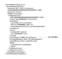
- FIG. 7 is a diagram showing an example of the content of the second control information in the device control system according to the embodiment of the present invention.
- FIG. 7 shows the second control information converted from the first control information by the protocol conversion unit 52 of the device control apparatus 11.
- the second designation information designates both “EV” and “EVSE” as the types of devices corresponding to “EV” designated in the first designation information.
- the “deviceCategory” line represents second designation information.
- “23580”, which is the content of the second designation information, indicates the target type.
- the content of the second designation information is expressed in hexadecimal.
- FIG. 8 is a diagram showing a correspondence relationship between the content of the second designation information and the target type in the device control system according to the embodiment of the present invention.
- table C shows the correspondence between the bit number of the bit string representing the content of the second designation information in binary number and the target type.
- “23580” that is the second designation information shown in FIG. 7 is a bit string of “00010001101011000000” in binary number.
- bit strings of “1” are 7, 8, 10, 12, 13, and 17.
- the second designation information shown in FIG. 7 includes “Smart Applications”, “Irrigation Pump”, “Simple misc. (Residental On / Off) loads”, “Interior Lighting”, “EV”, and “EVSE”. It can be seen that the following six are designated.
- Each device in the device control system includes a computer, and an arithmetic processing unit such as a CPU in the computer reads and executes a program including a part or all of each step in the following flowchart from a memory (not shown).
- an arithmetic processing unit such as a CPU in the computer reads and executes a program including a part or all of each step in the following flowchart from a memory (not shown).
- Each of the programs of the plurality of apparatuses can be installed from the outside.
- the programs of the plurality of apparatuses are distributed while being stored in a recording medium.
- FIG. 9 is a flowchart defining an example of an operation procedure when the device control apparatus converts the first control information into the second control information in the device control system according to the embodiment of the present invention.
- route information acquisition unit 54 acquires route information in response to an operation by a user (step S ⁇ b> 11), and sends the acquired route information to protocol conversion unit 52. .
- the protocol conversion unit 52 waits until the control information acquisition unit 51 receives the first control information (NO in step S12).
- the protocol conversion unit 52 converts the first control information received by the control information acquisition unit 51 into the second control information. (Step S13). At that time, the protocol conversion unit 52 performs association processing based on the route information received from the route information acquisition unit 54. The protocol conversion unit 52 sends second control information, which is information after conversion, to the transmission unit 53.
- the transmission unit 53 transmits the second control information received from the protocol conversion unit 52 to each device 12 (step S14).
- the second designation information can designate a larger number of device types than the first designation information.
- the present invention is not limited to this. It may be possible to designate a smaller number of device types than the first designation information.
- the device control apparatus 11 converts the first control information according to SEP2 into the second designation information according to SEP1. .
- both “EVSE” and “EV” can be designated as the first designation information included in the first control information.
- the second designation information included in the second control information “EV” can be designated, but “EVSE” cannot be designated.
- the protocol conversion unit 52 creates second designation information for designating “EV” when one or both of “EV” and “EVSE” are designated in the acquired first designation information.
- the device control device 11 is configured to perform protocol conversion of control information between SEP1 and SEP2, but is not limited thereto, and may be configured to perform protocol conversion of control information between different communication protocols. That's fine.
- the control information acquisition unit 51 acquires the first control information according to the first communication protocol.
- the protocol converter 52 converts the first control information into second control information according to the second communication protocol.
- the transmission unit 53 transmits the second control information to the device 12.
- the first control information includes first designation information that designates the type of device to be controlled.
- the second control information includes second designation information that designates the type of device to be controlled.
- the second designation information can designate a different number of device types from the first designation information.
- the route information acquisition unit 54 acquires route information related to the power supply route to each device 12. Based on the path information, the protocol conversion unit 52 associates the device type specified in the first specification information with the device type specified in the second specification information.
- the device 12 can be favorably controlled by appropriately converting control information according to different protocols.
- the protocol conversion unit 52 can specify a plurality of device types corresponding to the device type specified in the first specification information in the second specification information.
- second designation information that designates the type of the upstream device 12 in the power supply path among the plurality of types of devices that can be specified is created.
- each downstream device can be controlled by controlling the upstream device 12. Since the power supplied to the device 12 can be controlled, the power consumption of the downstream device 12 can be easily managed.
- the power consumption of the downstream device 12 can be controlled by controlling the upstream device 12. it can.
- a device control apparatus for controlling a plurality of devices in HEMS, A control information acquisition unit that acquires first control information according to SEP1, A protocol converter for converting the first control information into second control information according to SEP2, A transmission unit for transmitting the second control information to the device,
- the first control information includes first designation information for designating a type of device to be controlled
- the second control information includes second designation information that designates the type of device to be controlled,
- the second designation information can designate a larger number of device types than the first designation information
- a path information acquisition unit that acquires path information related to a power supply path to each of the devices
- the protocol conversion unit is a device control device that associates the type of the device designated in the first designation information with the type of the device designated in the second designation information based on the route information.
Landscapes
- Engineering & Computer Science (AREA)
- Computer Networks & Wireless Communication (AREA)
- Selective Calling Equipment (AREA)
- Information Transfer Systems (AREA)
Abstract
機器制御装置は、各機器への電力供給経路に関する経路情報を取得する経路情報取得部と、第1の通信プロトコルに従う第1の制御情報を取得する制御情報取得部と、前記第1の制御情報を、第2の通信プロトコルに従う第2の制御情報に変換するプロトコル変換部と、前記第2の制御情報を前記機器送信する送信部とを備える。前記第1の制御情報は、制御対象の機器の種類を指定する第1の指定情報を含み、前記第2の制御情報は、制御対象の機器の種類を指定する第2の指定情報を含み、前記第2の指定情報は、前記第1の指定情報と異なる数の機器の種類を指定可能である。前記プロトコル変換部は、前記経路情報に基づいて、前記第1の指定情報において指定された前記機器の種類を前記第2の指定情報において指定される前記機器の種類に対応付ける。
Description
本発明は、機器制御装置、機器制御システム、機器制御方法、および機器制御プログラムに関し、特に、プロトコル変換を行う機器制御装置、機器制御システム、機器制御方法、および機器制御プログラムに関する。
スマートハウス等の根幹となるエネルギーマネジメントシステムにおける通信プロトコルの策定が行われている。たとえば、通信プロトコルであるSEP2(Smart Energy Profile 2、「Smart Energy Profile 2 Application Protocol Standard」、ZigBee Alliance,Inc.and HomePlug Powerline Alliance,Inc.2013年4月発行(非特許文献1)参照)に対応するスマートハウスでは、宅内に設置されたスマートメータが空調および照明等の機器の動作内容を制御することにより、宅内における不必要なエネルギー消費を抑えることができる。
具体的には、たとえば、電力会社は、電力需給の逼迫が予想される場合に、電力需要家に対してデマンドレスポンス(Demand Response)を発行する。電力会社によりデマンドレスポンスが発行された場合、宅内のスマートメータは、機器の動作内容を制御するための制御情報をSEP2に従って作成して各機器へ送信する。
各機器は、自己がSEP2に対応している場合、スマートメータから受信した制御情報に従って、たとえば消費電力を抑えるように自己の動作内容を変更する。
「Smart Energy Profile 2 Application Protocol Standard」、ZigBee Alliance,Inc.and HomePlug Powerline Alliance,Inc.2013年4月発行
「ECHONET Lite規格書 Ver1.10」、エコーネットコンソーシアム、2013年5月31日発行
ところで、各機器がSEP2に対応している場合であっても、たとえば、スマートメータから出力される制御情報が旧来の通信プロトコルであるSEP1(Smart Energy Profile 1)に従うものである場合には、スマートメータおよび各機器間にプロトコル変換を行う装置を設置する必要がある。
しかしながら、SEP2に従う制御情報が制御対象とする機器の種類は、SEP1に従う制御情報が制御対象とする機器の種類と一部異なっている。このような異なるプロトコルに従う制御情報を適切に変換することにより、機器の制御を良好に行う技術が望まれる。
この発明は、上述の課題を解決するためになされたもので、その目的は、異なるプロトコルに従う制御情報を適切に変換することにより、機器の制御を良好に行うことが可能な機器制御装置、機器制御システム、機器制御方法、および機器制御プログラムを提供することである。
(1)上記課題を解決するために、この発明のある局面に係る機器制御装置は、複数の機器を制御する機器制御装置であって、各前記機器への電力供給経路に関する経路情報を取得する経路情報取得部と、第1の通信プロトコルに従う第1の制御情報を取得する制御情報取得部と、前記第1の制御情報を、第2の通信プロトコルに従う第2の制御情報に変換するプロトコル変換部と、前記第2の制御情報を前記機器へ送信する送信部とを備え、前記第1の制御情報は、制御対象の機器の種類を指定する第1の指定情報を含み、前記第2の制御情報は、制御対象の機器の種類を指定する第2の指定情報を含み、前記第2の指定情報は、前記第1の指定情報と異なる数の機器の種類を指定可能であり、前記プロトコル変換部は、前記経路情報に基づいて、前記第1の指定情報において指定された前記機器の種類を前記第2の指定情報において指定される前記機器の種類に対応付ける。
(3)上記課題を解決するために、この発明のある局面に係る機器制御システムは、スマートメータと、前記スマートメータから受信した制御情報から作成した別の制御情報により複数の機器を制御する機器制御装置とを含む機器制御システムであって、前記機器制御装置は、各前記機器への電力供給経路に関する経路情報を取得する経路情報取得部と、第1の通信プロトコルに従う第1の制御情報を取得する制御情報取得部と、前記第1の制御情報を、第2の通信プロトコルに従う第2の制御情報に変換するプロトコル変換部と、前記第2の制御情報を前記機器へ送信する送信部とを備え、前記第1の制御情報は、制御対象の機器の種類を指定する第1の指定情報を含み、前記第2の制御情報は、制御対象の機器の種類を指定する第2の指定情報を含み、前記第2の指定情報は、前記第1の指定情報と異なる数の機器の種類を指定可能であり、前記プロトコル変換部は、前記経路情報に基づいて、前記第1の指定情報において指定された前記機器の種類を前記第2の指定情報において指定される前記機器の種類に対応付ける。
(4)上記課題を解決するために、この発明のある局面に係る機器制御方法は、複数の機器を制御する機器制御方法であって、各前記機器への電力供給経路に関する経路情報を取得するステップと、第1の通信プロトコルに従う第1の制御情報を取得するステップと、前記第1の制御情報を、第2の通信プロトコルに従う第2の制御情報に変換するステップと、前記第2の制御情報を前記機器へ送信するステップとを含み、前記第1の制御情報は、制御対象の機器の種類を指定する第1の指定情報を含み、前記第2の制御情報は、制御対象の機器の種類を指定する第2の指定情報を含み、前記第2の指定情報は、前記第1の指定情報と異なる数の機器の種類を指定可能であり、前記第1の制御情報を前記第2の制御情報に変換するステップにおいては、前記経路情報に基づいて、前記第1の指定情報において指定された前記機器の種類を前記第2の指定情報において指定される前記機器の種類に対応付ける。
(5)上記課題を解決するために、この発明のある局面に係る機器制御プログラムは、複数の機器を制御する機器制御プログラムであって、コンピュータに、各前記機器への電力供給経路に関する経路情報を取得するステップと、第1の通信プロトコルに従う第1の制御情報を取得するステップと、前記第1の制御情報を、第2の通信プロトコルに従う第2の制御情報に変換するステップと、前記第2の制御情報を前記機器へ送信するステップとを実行させるためのプログラムであり、前記第1の制御情報は、制御対象の機器の種類を指定する第1の指定情報を含み、前記第2の制御情報は、制御対象の機器の種類を指定する第2の指定情報を含み、前記第2の指定情報は、前記第1の指定情報と異なる数の機器の種類を指定可能であり、前記第1の制御情報を前記第2の制御情報に変換するステップにおいては、前記経路情報に基づいて、前記第1の指定情報において指定された前記機器の種類を前記第2の指定情報において指定される前記機器の種類に対応付けるプログラムである。
本発明によれば、異なるプロトコルに従う制御情報を適切に変換することにより、機器の制御を良好に行うことができる。
最初に、本発明の実施の形態の内容を列記して説明する。
(1)本発明の実施の形態に係る機器制御装置は、複数の機器を制御する機器制御装置であって、各前記機器への電力供給経路に関する経路情報を取得する経路情報取得部と、第1の通信プロトコルに従う第1の制御情報を取得する制御情報取得部と、前記第1の制御情報を、第2の通信プロトコルに従う第2の制御情報に変換するプロトコル変換部と、前記第2の制御情報を前記機器へ送信する送信部とを備え、前記第1の制御情報は、制御対象の機器の種類を指定する第1の指定情報を含み、前記第2の制御情報は、制御対象の機器の種類を指定する第2の指定情報を含み、前記第2の指定情報は、前記第1の指定情報と異なる数の機器の種類を指定可能であり、前記プロトコル変換部は、前記経路情報に基づいて、前記第1の指定情報において指定された前記機器の種類を前記第2の指定情報において指定される前記機器の種類に対応付ける。
このような構成により、第1の指定情報により指定可能な機器の種類の数と第2の指定情報により指定可能な機器の種類の数とが異なる場合であっても、第1の指定情報において指定された機器の種類を第2の指定情報において指定する機器の種類に適切に対応付けることができる。したがって、異なるプロトコルに従う制御情報を適切に変換することにより、機器の制御を良好に行うことができる。
(2)好ましくは、前記プロトコル変換部は、前記第1の指定情報において指定された前記機器の種類に対応する前記機器の種類を前記第2の指定情報において複数指定可能な場合、指定可能な複数の前記機器の種類のうち、前記電力供給経路において上流側の前記機器の種類を指定する前記第2の指定情報を作成する。
このような構成により、たとえば、電力供給経路において、上流側の1つの機器の下流側に複数の機器が接続されている場合に、上流側の機器を制御することによって下流側の各機器へ供給される電力を制御することができるため、下流側の機器の消費電力の管理が容易になる。
また、たとえば、下流側の機器が外部からの制御を受ける機能を有しない場合であっても、上流側の機器を制御することにより、下流側の機器の消費電力を制御することができる。
(3)本発明の実施の形態に係る機器制御システムは、スマートメータと、前記スマートメータから受信した制御情報から作成した別の制御情報により複数の機器を制御する機器制御装置とを含む機器制御システムであって、前記機器制御装置は、各前記機器への電力供給経路に関する経路情報を取得する経路情報取得部と、第1の通信プロトコルに従う第1の制御情報を取得する制御情報取得部と、前記第1の制御情報を、第2の通信プロトコルに従う第2の制御情報に変換するプロトコル変換部と、前記第2の制御情報を前記機器へ送信する送信部とを備え、前記第1の制御情報は、制御対象の機器の種類を指定する第1の指定情報を含み、前記第2の制御情報は、制御対象の機器の種類を指定する第2の指定情報を含み、前記第2の指定情報は、前記第1の指定情報と異なる数の機器の種類を指定可能であり、前記プロトコル変換部は、前記経路情報に基づいて、前記第1の指定情報において指定された前記機器の種類を前記第2の指定情報において指定される前記機器の種類に対応付ける。
このような構成により、第1の指定情報により指定可能な機器の種類の数と第2の指定情報により指定可能な機器の種類の数とが異なる場合であっても、第1の指定情報において指定された機器の種類を第2の指定情報において指定する機器の種類に適切に対応付けることができる。したがって、異なるプロトコルに従う制御情報を適切に変換することにより、機器の制御を良好に行うことができる。
(4)本発明の実施の形態に係る機器制御方法は、複数の機器を制御する機器制御方法であって、各前記機器への電力供給経路に関する経路情報を取得するステップと、第1の通信プロトコルに従う第1の制御情報を取得するステップと、前記第1の制御情報を、第2の通信プロトコルに従う第2の制御情報に変換するステップと、前記第2の制御情報を前記機器へ送信するステップとを含み、前記第1の制御情報は、制御対象の機器の種類を指定する第1の指定情報を含み、前記第2の制御情報は、制御対象の機器の種類を指定する第2の指定情報を含み、前記第2の指定情報は、前記第1の指定情報と異なる数の機器の種類を指定可能であり、前記第1の制御情報を前記第2の制御情報に変換するステップにおいては、前記経路情報に基づいて、前記第1の指定情報において指定された前記機器の種類を前記第2の指定情報において指定される前記機器の種類に対応付ける。
このような方法により、第1の指定情報により指定可能な機器の種類の数と第2の指定情報により指定可能な機器の種類の数とが異なる場合であっても、第1の指定情報において指定された機器の種類を第2の指定情報において指定する機器の種類に適切に対応付けることができる。したがって、異なるプロトコルに従う制御情報を適切に変換することにより、機器の制御を良好に行うことができる。
(5)本発明の実施の形態に係る機器制御プログラムは、複数の機器を制御する機器制御プログラムであって、コンピュータに、各前記機器への電力供給経路に関する経路情報を取得するステップと、第1の通信プロトコルに従う第1の制御情報を取得するステップと、前記第1の制御情報を、第2の通信プロトコルに従う第2の制御情報に変換するステップと、前記第2の制御情報を前記機器へ送信するステップとを実行させるためのプログラムであり、前記第1の制御情報は、制御対象の機器の種類を指定する第1の指定情報を含み、前記第2の制御情報は、制御対象の機器の種類を指定する第2の指定情報を含み、前記第2の指定情報は、前記第1の指定情報と異なる数の機器の種類を指定可能であり、前記第1の制御情報を前記第2の制御情報に変換するステップにおいては、前記経路情報に基づいて、前記第1の指定情報において指定された前記機器の種類を前記第2の指定情報において指定される前記機器の種類に対応付けるプログラムである。
このような構成により、第1の指定情報により指定可能な機器の種類の数と第2の指定情報により指定可能な機器の種類の数とが異なる場合であっても、第1の指定情報において指定された機器の種類を第2の指定情報において指定する機器の種類に適切に対応付けることができる。したがって、異なるプロトコルに従う制御情報を適切に変換することにより、機器の制御を良好に行うことができる。
以下、本発明の実施の形態について図面を用いて説明する。なお、図中同一または相当部分には同一符号を付してその説明は繰り返さない。また、以下に記載する実施形態の少なくとも一部を任意に組み合わせてもよい。
[システム構成および基本動作]
図1は、本発明の実施の形態に係る機器制御システムの構成を示す図である。
図1は、本発明の実施の形態に係る機器制御システムの構成を示す図である。
図1を参照して、機器制御システム101は、電力管理サーバ10と、機器制御装置11と、複数の機器12と、スマートメータ15とを備える。
機器制御システム101は、たとえばHEMS(Home Energy Management System)である。電力管理サーバ10は、たとえば、電力会社に設置され、インターネットを介してスマートメータ15へ電力管理情報を送信する。
電力管理情報は、たとえば電力会社がデマンドレスポンスを発行する場合にスマートメータ15へ送信する情報であって、電力供給が逼迫していることを示す情報、日別もしくは時間帯別の電気料金情報、または、機器制御装置11が設置されている家屋全体の消費電力の節電要請を示す情報等である。
機器制御装置11と、機器12と、スマートメータ15とは、たとえば家屋5に設置される。機器制御装置11およびスマートメータ15は、互いに有線または無線で接続されている。また、機器制御装置11および機器12は、互いに有線または無線で接続されている。
スマートメータ15は、第1の通信プロトコルであるSEP1に対応しており、電力管理サーバ10から電力管理情報を受信し、受信した電力管理情報に基づいて、第1の通信プロトコルに従う制御情報である第1の制御情報を作成する。そして、スマートメータ15は、作成した第1の制御情報を機器制御装置11へ送信する。
制御情報は、機器12の動作を制御するための情報であって、制御対象の機器の種類を指定し、制御内容を含む。具体的には、制御情報は、制御対象の機器の種類を指定する指定情報、制御期間を示す期間指示情報および動作内容を示す動作指示情報等を含む。以下、指定情報において指定される制御対象の機器の種類を対象種類とも称する。
機器制御装置11は、スマートメータ15から受信した第1の制御情報に対してプロトコル変換を行い、プロトコル変換後の第2の制御情報を各機器12へ送信することによって各機器12を制御する。具体的には、機器制御装置11は、スマートメータ15から受信した第1の制御情報を、第2の通信プロトコルであるSEP2、に従う第2の制御情報に変換して各機器12へ送信する。なお、機器制御装置11は、各機器12の動作および消費電力を管理してもよい。
機器12は、エアコン、照明器、電気自動車充電設備(EVSE:Electric Vehicle Service Equipment)または電気自動車(EV:Electric Vehicle)等の機器であり、SEP2に対応している。すなわち、機器12は、SEP2に従う制御情報である第2の制御情報によって制御される。
機器12は、機器制御装置11から第2の制御情報を受信して、受信した制御情報が指定する対象種類を確認する。そして、機器12は、指定された対象種類と自己の種類とが一致する場合に、当該制御情報の内容に基づいて自己の動作内容を変更する。
具体的には、たとえば、機器12が室内照明器である場合において、当該室内照明器が受信した制御情報が、対象種類として「室内照明器」を指定し、午前9時以降に照明を暗くすることを指示する内容を含むときには、当該室内照明器は、受信した制御情報の内容に従って午前9時以降に自己の照明を暗くする。
図2は、本発明の実施の形態に係る機器制御システムが機器としてEVSEおよびEVを備える状態の一例を示す図である。
図2を参照して、機器制御システム101は、機器12として、EVSE17と複数のEV18とを備える。
機器制御装置11は、スマートメータ15から受信した第1の制御情報を第2の制御情報に変換して各機器12、ここではEVSE17および各EV18へ送信する。
EVSE17は、分電盤14から電力の供給を受ける。また、EVSE17は、機器制御装置11から受信した第2の制御情報が対象種類として「EVSE」を指定する場合には、当該制御情報の内容に従って動作する。
具体的には、たとえば、EVSE17は、受信した第2の制御情報が「EVSE」の出力電力を通常時より20%抑えることを指示する内容を含む場合には、EV18へ供給する電力の合計を通常時より20%抑えるように動作する。
各EV18は、EVSE17から電力の供給を受ける。すなわち、各EV18は、分電盤14からの電力供給経路において、EVSE17の下流側に存在する。
また、各EV18は、機器制御装置11から受信した第2の制御情報が対象種類として「EV」を指定する場合には、当該制御情報の内容に従って動作する。
具体的には、たとえば、EV18は、受信した第2の制御情報が「EV」の消費電力を通常時より20%抑えることを指示する内容を含む場合には、自己の消費電力、たとえば自己の充電に用いる電力を通常時より20%抑えるように動作する。
なお、各EV18は、第2の制御情報を機器制御装置11から直接受信する構成に限らず、EVSE17経由で受信する構成であってもよい。
ここで、第2の制御情報は、第1の制御情報より多数の対象種類を指定可能である。詳細には、第2の制御情報が含む指定情報(以下、第2の指定情報とも称する。)は、第1の制御情報が含む指定情報(以下、第1の指定情報とも称する。)よりも多数の機器の種類を指定可能である。
具体的には、たとえば、第1の指定情報は、「EV」を指定することができるが、「EVSE」を指定することができない。一方、第2の指定情報は、「EV」および「EVSE」の両方を指定可能である。
したがって、機器制御装置11は、第1の制御情報を第2の制御情報へ変換する際に、第1の指定情報において指定された機器の種類を第2の指定情報において指定される機器の種類に対応付ける。
以下、第1の指定情報において指定された機器の種類を第2の指定情報において指定される機器の種類に対応付ける処理を対応付け処理とも称する。
機器制御システム101にとっての適切な対応付け処理の内容は、各機器12の種類または接続関係によって異なる場合がある。そこで、たとえばユーザーは、機器制御装置11を操作することにより、機器制御装置11に対して、機器12への電力供給経路に関する情報である経路情報を入力する。そして、機器制御装置11は、第1の制御情報を第2の制御情報に変換する際、取得した経路情報に基づいて対応付け処理を行う。
ここで、経路情報は、たとえば、機器制御システム101が機器12として1つのEVSE17および2つのEV18を備えることを示す情報、EV18への電力供給経路の上流側にEVSE17が存在することを示す情報、およびEVSE17を制御することにより各EV18への供給電力を変更できることを示す情報である。
[機器制御装置の構成]
図3は、本発明の実施の形態に係る機器制御装置の構成を示す図である。
図3は、本発明の実施の形態に係る機器制御装置の構成を示す図である。
図3を参照して、機器制御装置11は、制御情報取得部51と、プロトコル変換部52と、送信部53と、経路情報取得部54とを含む。
経路情報取得部54は、ユーザーが機器制御装置11に対して入力した経路情報を取得し、取得した経路情報をプロトコル変換部52へ送る。なお、経路情報取得部54は、ユーザーによって入力された経路情報を取得する構成に限らず、たとえば、機器12と通信することによって経路情報を取得する構成であってもよい。
制御情報取得部51は、スマートメータ15から第1の制御情報を取得して、取得した第1の制御情報をプロトコル変換部52へ送る。
たとえば、第2の指定情報は、第1の指定情報において指定された機器の種類に対応する機器の種類を複数指定可能である。
具体的には、たとえば、機器制御装置11は、「EV」の消費電力を抑える指示を含む第1の制御情報を取得した場合、EVSE17を制御してEV18への供給電力を低下させるか、各EV18を制御して各EV18の充電電力を抑えるか、またはこれらの両方を行う。
したがって、機器制御装置11のプロトコル変換部52は、第1の指定情報において指定された「EV」を、第2の指定情報においては「EVSE」および「EV」のいずれか一方または両方に対応付けることができる。
上記のような場合において、プロトコル変換部52は、たとえば、第2の指定情報において指定可能な複数の機器12の種類のうち、機器12への電力供給経路において上流側の機器12の種類を指定する第2の指定情報を作成する。
具体的には、プロトコル変換部52は、経路情報取得部54から受けた経路情報に基づいて、EVSE17およびEV18のうち、EVSE17が上流側に存在することを認識する。
そして、プロトコル変換部52は、「EV」を対象種類とする第1の制御情報を受けた場合、つまり、「EV」を指定する指定情報を受けた場合には、EVSE17の種類である「EVSE」を指定する第2の指定情報を作成する。そして、プロトコル変換部52は、当該第2の指定情報を含む第2の制御情報を作成して送信部53へ送る。
送信部53は、プロトコル変換部52から受けた第2の制御情報を各機器12へ送信する。
なお、EVSE17は、複数のEV18と接続される構成に限らず、1つのEV18と接続される構成であってよい。
[制御情報のフォーマット]
図4は、本発明の実施の形態に係る機器制御システムにおける第1の制御情報のフォーマットの一例を示す図である。
図4は、本発明の実施の形態に係る機器制御システムにおける第1の制御情報のフォーマットの一例を示す図である。
図4を参照して、このフォーマットは、フィールドごとに区切られている。各フィールドには、1から13までの番号が付されている。
番号2のフィールドは、第1の指定情報を表す。第1の指定情報の内容である「06b0」は、対象種類を示している。なお、ここでは、第1の指定情報の内容は、16進数で表されている。
図5は、図4に示す制御情報のフォーマットにおける各フィールドの名称を示す図である。
図5を参照して、テーブルAは、図4に示す番号1から番号13までの各フィールドの名称を示している。第1の指定情報を表す番号2のフィールドの名称は、「Device Class」である。
図6は、図4に示す第1の指定情報の内容と対象種類との対応関係を示す図である。
図6を参照して、テーブルBは、第1の指定情報の内容を2進数で表したビット列のビット番号と対象種類との対応関係を示している。
具体的には、たとえば、図4に示す第1の指定情報である「06b0」は、2進数で表すと「011010110000」のビット列となる。
このビット列において、「1」となっているビットのビット番号は、4、5、7、9および10である。テーブルBから、図4に示す第1の指定情報は、「Smart Appliances」、「Irrigation Pump」、「Simple misc.(Residential On/Off)loads」、「Internal Lighting」および「EV」の5つを指定していることが分かる。
図7は、本発明の実施の形態に係る機器制御システムにおける第2の制御情報の内容の一例を示す図である。
図7は、機器制御装置11のプロトコル変換部52により第1の制御情報から変換された第2の制御情報を示している。当該第2の指定情報は、第1の指定情報において指定された「EV」に対応する機器の種類として、「EV」および「EVSE」の両方を指定する。
図7を参照して、「deviceCategory」の行は、第2の指定情報を表す。第2の指定情報の内容である「23580」は、対象種類を示している。なお、ここでは、第2の指定情報の内容は、16進数で表されている。
図8は、本発明の実施の形態に係る機器制御システムにおいて、第2の指定情報の内容と対象種類との対応関係を示す図である。
図8を参照して、テーブルCは、第2の指定情報の内容を2進数で表したビット列のビット番号と対象種類との対応関係を示している。
具体的には、たとえば、図7に示す第2の指定情報である「23580」は、2進数で表すと「000100011010110000000」のビット列となる。
このビット列のうち、「1」となっているビットのビット番号は、7、8、10、12、13および17である。テーブルCから、図7に示す第2の指定情報は、「Smart Appliances」、「Irrigation Pump」、「Simple misc.(Residential On/Off)loads」、「Interior Lighting」、「EV」および「EVSE」の6つを指定していることが分かる。
[動作]
機器制御システムにおける各装置は、コンピュータを備え、当該コンピュータにおけるCPU等の演算処理部は、以下のフローチャートの各ステップの一部または全部を含むプログラムを図示しないメモリから読み出して実行する。これら複数の装置のプログラムは、それぞれ、外部からインストールすることができる。これら複数の装置のプログラムは、それぞれ、記録媒体に格納された状態で流通する。
機器制御システムにおける各装置は、コンピュータを備え、当該コンピュータにおけるCPU等の演算処理部は、以下のフローチャートの各ステップの一部または全部を含むプログラムを図示しないメモリから読み出して実行する。これら複数の装置のプログラムは、それぞれ、外部からインストールすることができる。これら複数の装置のプログラムは、それぞれ、記録媒体に格納された状態で流通する。
図9は、本発明の実施の形態に係る機器制御システムにおいて、機器制御装置が第1の制御情報を第2の制御情報に変換する際の動作手順の一例を定めたフローチャートである。
図9を参照して、まず、機器制御装置11において、経路情報取得部54は、たとえばユーザーによる操作を受けて経路情報を取得し(ステップS11)、取得した経路情報をプロトコル変換部52へ送る。
次に、プロトコル変換部52は、制御情報取得部51が第1の制御情報を受信するまで待機する(ステップS12でNO)。
そして、プロトコル変換部52は、制御情報取得部51が第1の制御情報を受信した場合(ステップS12でYES)、制御情報取得部51によって受信された第1の制御情報を第2の制御情報に変換する(ステップS13)。その際、プロトコル変換部52は、経路情報取得部54から受けた経路情報に基づいて対応付け処理を行う。プロトコル変換部52は、変換後の情報である第2の制御情報を送信部53へ送る。
次に、送信部53は、プロトコル変換部52から受けた第2の制御情報を各機器12へ送信する(ステップS14)。
なお、本発明の実施の形態に係る機器制御システムでは、第2の指定情報は、第1の指定情報よりも多数の機器の種類を指定可能であるとしたが、これに限定するものではなく、第1の指定情報よりも少数の機器の種類を指定可能であってもよい。
たとえば、仮に、第1の通信プロトコルがSEP2であって、第2の通信プロトコルがSEP1である場合、機器制御装置11は、SEP2に従う第1の制御情報をSEP1に従う第2の指定情報へ変換する。
この場合、たとえば、第1の制御情報に含まれる第1の指定情報は、「EVSE」および「EV」の両方を指定可能である。一方、第2の制御情報に含まれる第2の指定情報は、「EV」を指定可能であるが、「EVSE」を指定することはできない。
プロトコル変換部52は、取得した第1の指定情報において「EV」および「EVSE」の一方または両方が指定されている場合、「EV」を指定する第2の指定情報を作成する。
また、機器制御装置11は、SEP1およびSEP2間において制御情報のプロトコル変換を行う構成としたが、これに限定するものではなく、相互に異なる通信プロトコル間において制御情報のプロトコル変換を行う構成であればよい。
ところで、第1の制御情報および第2の制御情報のように、異なるプロトコルに従う制御情報を適切に変換することにより、機器の制御を良好に行う技術が望まれる。
これに対して、本発明の実施の形態に係る機器制御装置では、制御情報取得部51は、第1の通信プロトコルに従う第1の制御情報を取得する。プロトコル変換部52は、第1の制御情報を、第2の通信プロトコルに従う第2の制御情報に変換する。送信部53は、第2の制御情報を機器12へ送信する。第1の制御情報は、制御対象の機器の種類を指定する第1の指定情報を含む。第2の制御情報は、制御対象の機器の種類を指定する第2の指定情報を含む。第2の指定情報は、第1の指定情報と異なる数の機器の種類を指定可能である。経路情報取得部54は、各機器12への電力供給経路に関する経路情報を取得する。プロトコル変換部52は、当該経路情報に基づいて、第1の指定情報において指定された機器の種類を第2の指定情報において指定される機器の種類に対応付ける。
このような構成により、第1の指定情報により指定可能な機器の種類の数と第2の指定情報により指定可能な機器の種類の数とが異なる場合であっても、第1の指定情報において指定された機器の種類を第2の指定情報において指定する機器の種類に適切に対応付けることができる。
したがって、本発明の実施の形態に係る機器制御装置では、異なるプロトコルに従う制御情報を適切に変換することにより、機器12の制御を良好に行うことができる。
また、本発明の実施の形態に係る機器制御装置では、プロトコル変換部52は、第1の指定情報において指定された機器の種類に対応する機器の種類を第2の指定情報において複数指定可能な場合、指定可能な複数の機器の種類のうち、電力供給経路において上流側の機器12の種類を指定する第2の指定情報を作成する。
このような構成により、たとえば、電力供給経路において、上流側の1つの機器12の下流側に複数の機器12が接続されている場合に、上流側の機器12を制御することによって下流側の各機器12へ供給される電力を制御することができるため、下流側の機器12の消費電力の管理が容易になる。
また、たとえば、下流側の機器12が外部からの制御を受ける機能を有しない場合であっても、上流側の機器12を制御することにより、下流側の機器12の消費電力を制御することができる。
上記実施の形態は、すべての点で例示であって制限的なものではないと考えられるべきである。本発明の範囲は、上記説明ではなく特許請求の範囲によって示され、特許請求の範囲と均等の意味および範囲内でのすべての変更が含まれることが意図される。
以上の説明は、以下に付記する特徴を含む。
[付記1]
HEMSにおける複数の機器を制御する機器制御装置であって、
SEP1に従う第1の制御情報を取得する制御情報取得部と、
前記第1の制御情報を、SEP2に従う第2の制御情報に変換するプロトコル変換部と、
前記第2の制御情報を前記機器へ送信する送信部とを備え、
前記第1の制御情報は、制御対象の機器の種類を指定する第1の指定情報を含み、
前記第2の制御情報は、制御対象の機器の種類を指定する第2の指定情報を含み、
前記第2の指定情報は、前記第1の指定情報よりも多数の機器の種類を指定可能であり、
さらに、
各前記機器への電力供給経路に関する経路情報を取得する経路情報取得部を備え、
前記プロトコル変換部は、前記経路情報に基づいて、前記第1の指定情報において指定された前記機器の種類を前記第2の指定情報において指定される前記機器の種類に対応付ける、機器制御装置。
HEMSにおける複数の機器を制御する機器制御装置であって、
SEP1に従う第1の制御情報を取得する制御情報取得部と、
前記第1の制御情報を、SEP2に従う第2の制御情報に変換するプロトコル変換部と、
前記第2の制御情報を前記機器へ送信する送信部とを備え、
前記第1の制御情報は、制御対象の機器の種類を指定する第1の指定情報を含み、
前記第2の制御情報は、制御対象の機器の種類を指定する第2の指定情報を含み、
前記第2の指定情報は、前記第1の指定情報よりも多数の機器の種類を指定可能であり、
さらに、
各前記機器への電力供給経路に関する経路情報を取得する経路情報取得部を備え、
前記プロトコル変換部は、前記経路情報に基づいて、前記第1の指定情報において指定された前記機器の種類を前記第2の指定情報において指定される前記機器の種類に対応付ける、機器制御装置。
5 家屋
10 電力管理サーバ
11 機器制御装置
12 機器
14 分電盤
15 スマートメータ
51 制御情報取得部
52 プロトコル変換部
53 送信部
54 経路情報取得部
101 機器制御システム
10 電力管理サーバ
11 機器制御装置
12 機器
14 分電盤
15 スマートメータ
51 制御情報取得部
52 プロトコル変換部
53 送信部
54 経路情報取得部
101 機器制御システム
Claims (5)
- 複数の機器を制御する機器制御装置であって、
各前記機器への電力供給経路に関する経路情報を取得する経路情報取得部と、
第1の通信プロトコルに従う第1の制御情報を取得する制御情報取得部と、
前記第1の制御情報を、第2の通信プロトコルに従う第2の制御情報に変換するプロトコル変換部と、
前記第2の制御情報を前記機器へ送信する送信部とを備え、
前記第1の制御情報は、制御対象の機器の種類を指定する第1の指定情報を含み、
前記第2の制御情報は、制御対象の機器の種類を指定する第2の指定情報を含み、
前記第2の指定情報は、前記第1の指定情報と異なる数の機器の種類を指定可能であり、
前記プロトコル変換部は、前記経路情報に基づいて、前記第1の指定情報において指定された前記機器の種類を前記第2の指定情報において指定される前記機器の種類に対応付ける、機器制御装置。 - 前記プロトコル変換部は、前記第1の指定情報において指定された前記機器の種類に対応する前記機器の種類を前記第2の指定情報において複数指定可能な場合、指定可能な複数の前記機器の種類のうち、前記電力供給経路において上流側の前記機器の種類を指定する前記第2の指定情報を作成する、請求項1に記載の機器制御装置。
- 請求項1に記載の機器制御装置を用いた機器制御システムであって、
スマートメータと、
前記スマートメータから受信した前記第1の制御情報から前記第2の制御情報を作成し、前記第2の制御情報を複数の前記機器に送信する前記機器制御装置と、を含む機器制御システム。 - 複数の機器を制御する機器制御方法であって、
各前記機器への電力供給経路に関する経路情報を取得するステップと、
第1の通信プロトコルに従う第1の制御情報を取得するステップと、
前記第1の制御情報を、第2の通信プロトコルに従う第2の制御情報に変換するステップと、
前記第2の制御情報を前記機器へ送信するステップとを含み、
前記第1の制御情報は、制御対象の機器の種類を指定する第1の指定情報を含み、
前記第2の制御情報は、制御対象の機器の種類を指定する第2の指定情報を含み、
前記第2の指定情報は、前記第1の指定情報と異なる数の機器の種類を指定可能であり、
前記第1の制御情報を前記第2の制御情報に変換するステップにおいては、前記経路情報に基づいて、前記第1の指定情報において指定された前記機器の種類を前記第2の指定情報において指定される前記機器の種類に対応付ける、機器制御方法。 - 複数の機器を制御する機器制御プログラムであって、コンピュータに、
各前記機器への電力供給経路に関する経路情報を取得するステップと、
第1の通信プロトコルに従う第1の制御情報を取得するステップと、
前記第1の制御情報を、第2の通信プロトコルに従う第2の制御情報に変換するステップと、
前記第2の制御情報を前記機器へ送信するステップとを実行させるためのプログラムであり、
前記第1の制御情報は、制御対象の機器の種類を指定する第1の指定情報を含み、
前記第2の制御情報は、制御対象の機器の種類を指定する第2の指定情報を含み、
前記第2の指定情報は、前記第1の指定情報と異なる数の機器の種類を指定可能であり、
前記第1の制御情報を前記第2の制御情報に変換するステップにおいては、前記経路情報に基づいて、前記第1の指定情報において指定された前記機器の種類を前記第2の指定情報において指定される前記機器の種類に対応付ける、機器制御プログラム。
Applications Claiming Priority (2)
| Application Number | Priority Date | Filing Date | Title |
|---|---|---|---|
| JP2014058072A JP5884848B2 (ja) | 2014-03-20 | 2014-03-20 | 機器制御装置、機器制御システム、機器制御方法、および機器制御プログラム |
| JP2014-058072 | 2014-03-20 |
Publications (1)
| Publication Number | Publication Date |
|---|---|
| WO2015141019A1 true WO2015141019A1 (ja) | 2015-09-24 |
Family
ID=54144018
Family Applications (1)
| Application Number | Title | Priority Date | Filing Date |
|---|---|---|---|
| PCT/JP2014/066374 Ceased WO2015141019A1 (ja) | 2014-03-20 | 2014-06-20 | 機器制御装置、機器制御システム、機器制御方法、および機器制御プログラム |
Country Status (2)
| Country | Link |
|---|---|
| JP (1) | JP5884848B2 (ja) |
| WO (1) | WO2015141019A1 (ja) |
Citations (3)
| Publication number | Priority date | Publication date | Assignee | Title |
|---|---|---|---|---|
| WO2006126355A1 (ja) * | 2005-05-24 | 2006-11-30 | Matsushita Electric Industrial Co., Ltd. | ゲートウェイ装置及び制御装置 |
| JP2012100074A (ja) * | 2010-11-02 | 2012-05-24 | Sharp Corp | 通信アダプタ |
| JP2013134603A (ja) * | 2011-12-26 | 2013-07-08 | Daiwa House Industry Co Ltd | エネルギー管理システム及びエネルギー管理方法 |
-
2014
- 2014-03-20 JP JP2014058072A patent/JP5884848B2/ja not_active Expired - Fee Related
- 2014-06-20 WO PCT/JP2014/066374 patent/WO2015141019A1/ja not_active Ceased
Patent Citations (3)
| Publication number | Priority date | Publication date | Assignee | Title |
|---|---|---|---|---|
| WO2006126355A1 (ja) * | 2005-05-24 | 2006-11-30 | Matsushita Electric Industrial Co., Ltd. | ゲートウェイ装置及び制御装置 |
| JP2012100074A (ja) * | 2010-11-02 | 2012-05-24 | Sharp Corp | 通信アダプタ |
| JP2013134603A (ja) * | 2011-12-26 | 2013-07-08 | Daiwa House Industry Co Ltd | エネルギー管理システム及びエネルギー管理方法 |
Also Published As
| Publication number | Publication date |
|---|---|
| JP5884848B2 (ja) | 2016-03-15 |
| JP2015185885A (ja) | 2015-10-22 |
Similar Documents
| Publication | Publication Date | Title |
|---|---|---|
| US8190275B2 (en) | Peer-to-peer home automation management | |
| US11038706B2 (en) | Method for automatic configuration of sematic-based projects in building automation systems | |
| US9124132B2 (en) | Automated demand response gateway | |
| JP5703207B2 (ja) | エネルギー管理システム及び管理装置 | |
| US20110266869A1 (en) | Method and system for measuring, monitoring and controlling electrical power consumption | |
| JP6080457B2 (ja) | エネルギー消費機器制御装置、エネルギー消費機器制御方法及びエネルギー消費機器制御システム | |
| US20150148961A1 (en) | Building data managing apparatus and building management system comprising thereof | |
| KR101866702B1 (ko) | 클라우드 컴퓨팅을 위한 스마트팜용 통신모듈 분리형 사물인터넷 제어기 및 이를 이용한 제어방법 | |
| CN104506448B (zh) | 一种物联网自适应的智能路由器 | |
| US20140203092A1 (en) | Communicating thermostat recovery algorithm | |
| CN115668869B (zh) | 建筑物管理系统元数据的远程发现 | |
| CN110703616A (zh) | 一种智能交互方法、云服务器、智能交互系统及存储介质 | |
| US20150256650A1 (en) | Network system, communication method, server, and terminal | |
| CN105318488B (zh) | 管道式空调器及其控制方法 | |
| CN105849789B (zh) | 管理对通过红外控制信号可控的电子设备的控制 | |
| CN106096533A (zh) | 用于确定电可操作机器的身份信息的系统和方法 | |
| JP5884848B2 (ja) | 機器制御装置、機器制御システム、機器制御方法、および機器制御プログラム | |
| JP2013207705A (ja) | 制御装置 | |
| CN102954558B (zh) | 空调控制方法和装置 | |
| CN105573300A (zh) | 一种基于物联网的数据采集复制系统及其控制方法 | |
| US20140039715A1 (en) | System-side controller and method | |
| KR101677131B1 (ko) | 블루투스를 이용한 조명 제어 시스템 | |
| JP2017168954A (ja) | 電源アダプタ | |
| US20130257163A1 (en) | System and method for controlling solar power conversion systems | |
| KR102134691B1 (ko) | 프로토콜 변환 장치 |
Legal Events
| Date | Code | Title | Description |
|---|---|---|---|
| 121 | Ep: the epo has been informed by wipo that ep was designated in this application |
Ref document number: 14886635 Country of ref document: EP Kind code of ref document: A1 |
|
| NENP | Non-entry into the national phase |
Ref country code: DE |
|
| 122 | Ep: pct application non-entry in european phase |
Ref document number: 14886635 Country of ref document: EP Kind code of ref document: A1 |