WO2015141007A1 - Système d'enregistrement/authentification biométrique et procédé d'enregistrement/authentification biométrique - Google Patents
Système d'enregistrement/authentification biométrique et procédé d'enregistrement/authentification biométrique Download PDFInfo
- Publication number
- WO2015141007A1 WO2015141007A1 PCT/JP2014/057882 JP2014057882W WO2015141007A1 WO 2015141007 A1 WO2015141007 A1 WO 2015141007A1 JP 2014057882 W JP2014057882 W JP 2014057882W WO 2015141007 A1 WO2015141007 A1 WO 2015141007A1
- Authority
- WO
- WIPO (PCT)
- Prior art keywords
- living body
- information
- authentication
- authentication system
- user
- Prior art date
Links
Images


Classifications
-
- A—HUMAN NECESSITIES
- A61—MEDICAL OR VETERINARY SCIENCE; HYGIENE
- A61B—DIAGNOSIS; SURGERY; IDENTIFICATION
- A61B5/00—Measuring for diagnostic purposes; Identification of persons
- A61B5/117—Identification of persons
- A61B5/1171—Identification of persons based on the shapes or appearances of their bodies or parts thereof
-
- A—HUMAN NECESSITIES
- A61—MEDICAL OR VETERINARY SCIENCE; HYGIENE
- A61B—DIAGNOSIS; SURGERY; IDENTIFICATION
- A61B5/00—Measuring for diagnostic purposes; Identification of persons
- A61B5/103—Detecting, measuring or recording devices for testing the shape, pattern, colour, size or movement of the body or parts thereof, for diagnostic purposes
- A61B5/11—Measuring movement of the entire body or parts thereof, e.g. head or hand tremor, mobility of a limb
- A61B5/1113—Local tracking of patients, e.g. in a hospital or private home
- A61B5/1114—Tracking parts of the body
-
- A—HUMAN NECESSITIES
- A61—MEDICAL OR VETERINARY SCIENCE; HYGIENE
- A61B—DIAGNOSIS; SURGERY; IDENTIFICATION
- A61B5/00—Measuring for diagnostic purposes; Identification of persons
- A61B5/48—Other medical applications
- A61B5/4887—Locating particular structures in or on the body
- A61B5/489—Blood vessels
-
- A—HUMAN NECESSITIES
- A61—MEDICAL OR VETERINARY SCIENCE; HYGIENE
- A61B—DIAGNOSIS; SURGERY; IDENTIFICATION
- A61B5/00—Measuring for diagnostic purposes; Identification of persons
- A61B5/68—Arrangements of detecting, measuring or recording means, e.g. sensors, in relation to patient
- A61B5/6801—Arrangements of detecting, measuring or recording means, e.g. sensors, in relation to patient specially adapted to be attached to or worn on the body surface
- A61B5/6813—Specially adapted to be attached to a specific body part
- A61B5/6825—Hand
- A61B5/6826—Finger
-
- G—PHYSICS
- G06—COMPUTING; CALCULATING OR COUNTING
- G06F—ELECTRIC DIGITAL DATA PROCESSING
- G06F21/00—Security arrangements for protecting computers, components thereof, programs or data against unauthorised activity
- G06F21/30—Authentication, i.e. establishing the identity or authorisation of security principals
- G06F21/31—User authentication
- G06F21/32—User authentication using biometric data, e.g. fingerprints, iris scans or voiceprints
-
- G—PHYSICS
- G06—COMPUTING; CALCULATING OR COUNTING
- G06Q—INFORMATION AND COMMUNICATION TECHNOLOGY [ICT] SPECIALLY ADAPTED FOR ADMINISTRATIVE, COMMERCIAL, FINANCIAL, MANAGERIAL OR SUPERVISORY PURPOSES; SYSTEMS OR METHODS SPECIALLY ADAPTED FOR ADMINISTRATIVE, COMMERCIAL, FINANCIAL, MANAGERIAL OR SUPERVISORY PURPOSES, NOT OTHERWISE PROVIDED FOR
- G06Q20/00—Payment architectures, schemes or protocols
- G06Q20/38—Payment protocols; Details thereof
- G06Q20/40—Authorisation, e.g. identification of payer or payee, verification of customer or shop credentials; Review and approval of payers, e.g. check credit lines or negative lists
- G06Q20/401—Transaction verification
- G06Q20/4014—Identity check for transactions
- G06Q20/40145—Biometric identity checks
-
- G—PHYSICS
- G07—CHECKING-DEVICES
- G07C—TIME OR ATTENDANCE REGISTERS; REGISTERING OR INDICATING THE WORKING OF MACHINES; GENERATING RANDOM NUMBERS; VOTING OR LOTTERY APPARATUS; ARRANGEMENTS, SYSTEMS OR APPARATUS FOR CHECKING NOT PROVIDED FOR ELSEWHERE
- G07C9/00—Individual registration on entry or exit
- G07C9/30—Individual registration on entry or exit not involving the use of a pass
- G07C9/32—Individual registration on entry or exit not involving the use of a pass in combination with an identity check
- G07C9/37—Individual registration on entry or exit not involving the use of a pass in combination with an identity check using biometric data, e.g. fingerprints, iris scans or voice recognition
-
- A—HUMAN NECESSITIES
- A61—MEDICAL OR VETERINARY SCIENCE; HYGIENE
- A61B—DIAGNOSIS; SURGERY; IDENTIFICATION
- A61B2576/00—Medical imaging apparatus involving image processing or analysis
- A61B2576/02—Medical imaging apparatus involving image processing or analysis specially adapted for a particular organ or body part
-
- G—PHYSICS
- G07—CHECKING-DEVICES
- G07C—TIME OR ATTENDANCE REGISTERS; REGISTERING OR INDICATING THE WORKING OF MACHINES; GENERATING RANDOM NUMBERS; VOTING OR LOTTERY APPARATUS; ARRANGEMENTS, SYSTEMS OR APPARATUS FOR CHECKING NOT PROVIDED FOR ELSEWHERE
- G07C2209/00—Indexing scheme relating to groups G07C9/00 - G07C9/38
- G07C2209/02—Access control comprising means for the enrolment of users
-
- G—PHYSICS
- G16—INFORMATION AND COMMUNICATION TECHNOLOGY [ICT] SPECIALLY ADAPTED FOR SPECIFIC APPLICATION FIELDS
- G16H—HEALTHCARE INFORMATICS, i.e. INFORMATION AND COMMUNICATION TECHNOLOGY [ICT] SPECIALLY ADAPTED FOR THE HANDLING OR PROCESSING OF MEDICAL OR HEALTHCARE DATA
- G16H30/00—ICT specially adapted for the handling or processing of medical images
- G16H30/40—ICT specially adapted for the handling or processing of medical images for processing medical images, e.g. editing
Definitions
- the present invention relates to a biometric registration and authentication system that registers biometric information and authenticates the biometric information.
- biometric authentication technology for authenticating a user using biometric information is used in various facilities and transaction systems such as door access and ATM.
- a biometric registration / authentication system using such technology, it is necessary to register biometric information of the user in advance in the system. That is, when the body part of the body determined by the system, such as a finger or an eye, is held over the imaging unit at the time of registration, the biometric registration / authentication system acquires the biological information and obtains the characteristic component from the acquired biological information. After extracting a certain biometric feature, it is registered in the user information storage unit as the information of the user.
- the user again holds the region of the body registered in the system over the living body imaging unit, and the living body registration / authentication system acquires living body information and extracts the living body feature amount from the acquired living body information. Then, the similarity is calculated by comparing and collating the extracted biometric feature with the biometric feature of the user registered in advance in the user information storage unit, and the calculated similarity exceeds a certain threshold. If it does, it authenticates as the person, and if it does not exceed, it authenticates as not being the person.
- the holding state of the living body varies between registration and authentication, there may occur a case where the user is incorrectly determined not to be the user.
- the user In order to authenticate the user with high accuracy, the user holds the defined body part at the proper position with respect to the living body imaging unit as much as possible and without blurring at the time of registration and at the time of authentication. It is necessary to make an effort to obtain feature quantities.
- Patent Document 1 Patent Document 2
- Patent Document 3 Patent Document 3
- the imaging unit when acquiring biological information, captures an image of a predetermined site when the user operates and acquires an operation image at the time of authentication, and the operation image and the predetermined site are registered in advance.
- a technique is disclosed that compares the registered operation image with one another and guides the operation according to the comparison result.
- Patent Document 2 it is judged whether the finger is properly arranged using the imaged vein information of the finger, and it is judged that the finger is not properly arranged.
- a technique is disclosed that notifies any one or more of the above arrangement state and part.
- Patent Document 3 when the biometric information is registered, the biometric information detected by the first detection unit and the contact position detected by the second detection unit are stored in the storage unit, and stored when the biometric information is authenticated.
- stored in the part is disclosed.
- Patent Document 1 does not show a specific processing method for qualitatively and quantitatively measuring the displacement of the held body, so in carrying out the invention, research and develop the processing method. There is room to be done and it is difficult to implement immediately.
- the present invention has been made in view of the above, and it is an object of the present invention to further reduce the authentication failure due to various actions causing dispersion of the holding state of a living body as compared with the prior art.
- the biometric registration / authentication system comprises an imaging unit for imaging a first living body used for registration or authentication, and a second one other than the first living body. Whether the holding state of the first living body to the imaging unit is appropriate is determined based on the acquiring unit for acquiring the characteristic information of the living body biological information and the characteristic information of the second living body information. And a control unit to configure a biometric registration and authentication system.
- the biometric registration / authentication system images the first living organism used for registration or authentication, and acquires the characteristic information of the first biometric information that is the biometric information of the first living organism imaged.
- a control unit which determines whether or not the holding state of the first living body to the imaging acquisition unit is appropriate based on the characteristic information of the first biological information.
- a biometric registration and authentication system comprising: a biometric registration and authentication device; and a palm rest which is detachable from the biometric registration and authentication device and on which a second living body other than the first living body is placed. Configured as
- the present invention is also understood as a biometric registration and authentication method performed in the above biometric registration and authentication system.
- the present invention it is possible to reduce authentication failure due to various actions that disperse the holding state of the living body, as compared to the prior art.
- FIG. 1 is a view showing a configuration example of a biometric registration / authentication system 1000 according to the present invention.
- the biometric registration / authentication system 1000 includes an overall control unit 101, a user registration control unit 102, a user authentication control unit 103, a living body imaging unit 104, a touch pad 105, an information display unit 106, and information input.
- the configuration includes a unit 107 and a user information storage unit 108.
- the respective constituent elements 101 to 108 are connected by a data communication unit 109 such as an I / O bus, and can mutually transmit and receive data.
- the overall control unit 101 controls the components 102 to 108 in an orderly manner via the data communication unit 109, performs registration processing for registering the user in the biometric registration and authentication system 1000, and authenticates the user as a specific individual. Execute authentication process.
- the user registration control unit 102 controls various processes to be executed when registering the biometric information of the user in the biometric registration / authentication system 1000. Specifically, although described later, when the living body imaging unit 104 captures and acquires the biometric information of the user, the user registration control unit 102 extracts the biometric feature amount that is the feature of the user individual from the biometric information. . The user registration control unit 102 stores the extracted biometric feature amount in the user information storage unit 108 as registration data of the individual user.
- the user authentication control unit 103 controls various processes to be performed when authenticating a user registered in the biometric registration / authentication system 1000.
- the living body imaging unit 104 captures and acquires the biometric information of the user
- the user authentication control unit 103 extracts a biometric feature amount that is a feature of the user individual from the biometric information.
- the user authentication control unit 103 compares and collates the extracted biometric feature amount with the biometric feature amount registered in advance in the user information storage unit 108, and calculates the degree of similarity between the two.
- the user authentication control unit 103 authenticates whether the user is a specific individual or not by whether the calculated degree of similarity exceeds a certain threshold.
- the specific process which each control part performs is later mentioned using a flowchart.
- the living body imaging unit 104 acquires living body information of a first living body of the user's living body.
- the first living body is a living body used for registration and authentication in the present system.
- a finger vein pattern is described as an example of biological information acquired by the living body imaging unit 104.
- the palm vein pattern may be used if the features are different for each individual of the user and are easily distinguishable.
- a variety of biological information represented by fingerprint patterns, iris patterns, palm contours, and facial features can be used.
- the touch pad 105 acquires touch information on the touch pad 105 of the second living body of the user.
- the contact information is information obtained from the second living body in contact with the touch pad 105.
- the second living body is a living body other than the first living body, and is a living body that can be an object of registration or authentication in the present system. For example, when the first living body in finger authentication is the forefinger of the right hand, the second living body is the right middle finger or palm other than the forefinger of the right hand.
- the user registration control unit 102 and the user authentication control unit 103 analyze the acquired contact information to determine whether the first living body is appropriately held over the living body imaging unit 104 or not. judge.
- the living body imaging unit 104 and the touch pad 105 preferably, when the first living body is held by the living body imaging unit 104, the second living body does not notice the user's touch pad. It is desirable that the living body imaging unit 104 and the touch pad 105 be disposed adjacent to each other so as to contact 105. An example of the arrangement is shown in FIGS. 2A to 3 and the details will be described later.
- the information display unit 106 displays various information related to biometric registration and authentication such as a menu screen and operation guidance in the biometric registration and authentication system 1000, and an authentication result.
- the information input unit 107 receives input of various information related to biometric registration and authentication.
- the information input unit 107 may input ID information for identifying a user in the biometric registration / authentication system 1000 or the type of a living body to be registered (for finger authentication, the type of a finger such as a thumb or forefinger).
- the input is accepted by an operation such as a keyboard, a mouse, or a screen touch.
- the user information storage unit 108 is an information storage device or medium such as a hard disk, and stores information unique to each user of the user including biometric information. An example of data to be stored is shown in FIG. 13 and the details will be described later.
- touch pad 105 the information display unit 106, and the information input unit 107 have been described as individual components for convenience of explanation, they may be replaced with the touch panel 110, for example, to serve as touch sensor, information display, and information input functions. It may be one component if aligned. Further, the information display unit 106 and the information input unit 107 may be provided in an apparatus, apparatus or system other than this system.
- the data communication unit 109 does not have to be an I / O bus in particular, and may be any means capable of transmitting and receiving data, such as USB connection and TCP / IP connection.
- the respective constituent elements 101 to 108 may be integrated in one casing or physically separated as long as data communication can be performed by the data communication unit 109.
- the respective units of the overall control unit 101, the user registration control unit 102, the user authentication control unit 103, and the user information storage unit 108 are held on the personal computer (PC) or automated teller machine (ATM) side
- the unit 104 and the touch pad 105 may be disposed on the biometric registration / authentication device side.
- FIG. 2A is a perspective view of an arrangement example of the living body imaging unit 104 and the touch pad 105 in the present embodiment.
- the touch pad 105 is disposed on the surface of the palm rest 204 so as to surround the living body imaging unit 104.
- the living body imaging unit 104 is physically and electrically connected to a device, apparatus, or system using the biometric authentication system 1000 via a data communication cable 203 represented by USB. Examples of these devices, devices, and systems include devices, devices, and systems that require user authentication, as represented by, for example, a PC, an ATM, or a system using them.
- the right middle finger is shown as an assumed position 201 of the right hand when held up to the living body imaging unit 104.
- the middle finger of the user's right hand is held up on the living body imaging unit 104, the remaining four fingers and palms touch the touch pad 105, and the contact information on the touch pad 105 as the contact portion 202 unknowingly It is acquired.
- the living body imaging unit 104 and the touch pad 105 may not be arranged as illustrated, and when the first living body is held by the living body imaging unit 104, the touch pad 105 may contact the second living body. Information may be acquired, and the acquired contact information may be analyzed to analyze the information to determine whether or not the holding state of the first living body to the biological imaging unit 104 is appropriate.
- the biological body imaging part 104 into the trapezoid shape which made the fingertip side the base.
- the fingertip side is wider than the root side, the user can hold the finger more easily than in the case of the rectangular shape as shown in FIG. 2A.
- FIG. 2C it is also possible to set it as the trapezoid shape which expanded the trapezoid shape shown to FIG. 2B to the width direction of a finger
- the present invention is not limited to these shapes, and can be suitably changed according to the shape of the living body, such as the thickness of the finger of the user, the size of the palm, etc.
- the sensing area of the touch pad is finely divided into unit areas in vertical and horizontal grids, and binary information indicating whether a living body is in contact is data for each unit area. It is conceivable to sequentially output from the communication cable 203. By converting touch information of all unit areas into surface data and re-integrating the touch information as one entire area, analysis of touch information becomes relatively easy. In addition, preferably, it is more accurate to hold the contact pressure of the living body in multiple values (including the non-contact state) for each unit area using the pressure-sensitive touch pad 105 or not. Can be determined.
- FIG. 3 is a side view of the arrangement example of the living body imaging unit 104 and the touch pad 105 shown in FIGS. 2A to 2C.
- the contact portion 202 a portion of the thumb and a portion of the palm are shown linearly, but in fact, the contact information is surface information that spreads in the vertical and horizontal directions.
- FIG. 4 illustrates an example of contact information obtained from the touch pad 105 when the middle finger of the right hand is held over the living body imaging unit 104 in the registration process or authentication process of biological information.
- the entire palm is in contact with the touch pad, and the contact portion 401 appears as a palm shape.
- contact information in a range of lumps such as the contact portion 401 is referred to as a land for convenience.
- the living body imaging unit 104 does not align the functions of the touch pad 105, so contact information is not obtained for the portion 402 of the middle finger held by the living body imaging unit 104. .
- this is not limited as a feature of the present invention, and the living body imaging unit 104 also functions as the touch pad 105, and contacts the portion displayed as the non-contact portion 402 as well as the contact portion 401. Information may be acquired.
- FIG. 5 is an example of a flowchart illustrating a processing procedure of acquiring touch information from the touch pad 105 and extracting a touch feature amount from the acquired touch information.
- the contact feature quantity is a feature quantity for grasping the holding state of the living body.
- step S501 the touch pad 105 acquires contact information of a living body.
- the contact information of the living body is obtained as a binary information group indicating whether or not the living body is in contact with each unit area, or a multi-valued information group indicating the contact pressure. Be done.
- step S502 the user registration control unit 102 reconstructs the contact information for each unit area obtained in step S501 as surface data. That is, in order to easily handle the binary information group or multi-level information group acquired in step S501, the user registration control unit 102 associates these values with the unit area and performs rearrangement processing in the vertical and horizontal directions.
- step S503 the user registration control unit 102 smoothes the contact information reconstructed in step S502.
- the smoothing is, for example, removing a land whose area is less than a certain threshold value, connecting the land when the distance between the lands is less than a certain threshold value, and connecting the outline of each land at that time.
- step S504 the user registration control unit 102 counts how many lands exist from the contact information smoothed in step S503.
- the number of lands is one. Note that the number of lands is treated as a type of contact feature.
- step S505 based on the contact information smoothed in step S503, the user registration control unit 102 calculates the barycentric point coordinate group g1 (x1, y1), g2 (x2, y2), ..., gn (xn, x) of each land. yn) (if the number of lands is n) is determined.
- a center-of-gravity point coordinate group is determined in consideration of the obtained contact pressure. For example, the barycentric point coordinate group is determined by multiplying the value with a larger value as the contact pressure is larger. The center-of-gravity point coordinate group thus obtained is treated as a kind of contact feature value.
- step S506 the user registration control unit 102 scans the contact information smoothed in step S503 for each vertical line, counts how many unit areas with which a living body is in contact, and creates a histogram. .
- weighting is performed corresponding to the contact pressure for each unit area and counting is performed to create a histogram.
- the created histogram is treated as a type of touch feature.
- step S507 the user registration control unit 102 scans the contact information smoothed in step S503 for each horizontal line, counts how many unit areas with which a living body is in contact, and creates a histogram. .
- weighting is performed corresponding to the contact pressure for each unit area and counting is performed to create a histogram.
- the created histogram is treated as a type of touch feature.
- the user registration control unit 102 exceeds a specific threshold value for each of the four types of contact features (the number of lands, the barycentric point coordinate group, and the histograms scanned in the vertical and horizontal directions) extracted in the above processing procedure.
- a specific threshold value for each of the four types of contact features (the number of lands, the barycentric point coordinate group, and the histograms scanned in the vertical and horizontal directions) extracted in the above processing procedure.
- To the living body imaging unit 104 by checking whether or not it is a combination of specific ranges, and further checking whether or not the check result is a specific combination. It is possible to determine whether the holding state is appropriate. An example of whether or not the holding state of the living body is appropriate will be described later.
- the user registration control unit 102 continuously executes the above-described processing procedure, and checks whether or not each time-sequential change in the touch feature amount is equal to or less than a certain threshold value to obtain a living body imaging unit. It is also possible to determine whether the living body being held at 104 is substantially stationary and is in a state suitable for acquiring biological information.
- the contact feature amounts are the four types described above, the contact features are not particularly limited to the above four types, and the contact feature amounts can accurately determine the holding state of the living body to the living body imaging unit 104 I hope there is.
- FIG. 6 is an example in which a touch feature amount is extracted from the touch information shown in FIG.
- the barycentric point 601 is the barycentric point of the land 401, and represents the coordinates (the barycentric point coordinates).
- the vertical scanning histogram 602 represents the size of the value obtained by the user registration control unit 102 scanning the image for each vertical line and counting the unit area in contact with the living body for each vertical line.
- the horizontal direction scanning histogram 603 represents the size of the value obtained by the user registration control unit 102 scanning the image for each horizontal line and counting the unit area in contact with the living body for each horizontal line.
- the right middle finger 402 is appropriately held by the living body imaging unit 104.
- the right-hand middle finger 402 held on the living body imaging unit 104 is not bent or lifted, and the inside of the finger is facing straight to the living body imaging unit 104.
- the entire palm is in contact with the touch pad 105 with uniform pressure, thereby reducing the number of lands.
- the number of lands is one.
- the user registration control unit 102 checks the number of lands and checks whether the number is less than or equal to a certain threshold to properly hold the living body on the living body imaging unit 104. It is possible to determine For example, when the right middle finger 402 is appropriately held, the land number is 1, the barycentric coordinates of the land are located approximately at the center of the palm, and the vertical scanning histogram 602 and the horizontal scanning histogram 603 have deviations. Since the condition does not exist, it is possible to determine that the living body is appropriately held if the condition or a threshold having a certain width in the condition is satisfied.
- the ideal barycentric point coordinates serving as a reference when each finger such as the index finger, the middle finger, and the ring finger is appropriately held by the living body imaging unit 105, and the histogram are associated with each finger and registered in the system in advance.
- the user registration control unit 102 compares the obtained barycentric point 601, the vertical scanning histogram 602, and the horizontal scanning histogram 603 with the touch feature values registered in advance, and which finger is touched It is possible to determine the type of the finger held by the living body imaging unit 104 by examining whether it is most similar to the touch feature value at the time of shooting. Of course, the type of finger may be determined in comparison with the touch feature amount of each finger registered by the user in the past.
- FIG. 7 is another example of the touch information obtained from the touch pad and the extracted touch feature quantity.
- FIG. 7 shows an example in which the right middle finger 713 is held by the living body imaging unit 104 in an inappropriate state. Specifically, when the belly of the right middle finger 713 held on the living body imaging unit 104 does not face straight to the living body imaging unit 104 and the finger is slightly rotated to the right about the base of the fingertip and the base of the finger.
- the user registration control unit 102 obtains center of gravity points 706 to 710 for the lands 701 to 705, respectively. In the example of FIG. 7, the number of lands is five, and the vertical scanning histogram 711 and the horizontal scanning histogram 712 are not substantially symmetrical but are output in a biased manner.
- FIG. 8 is another example of the touch information obtained from the touch pad and the extracted touch feature quantity.
- FIG. 8 shows an example in which the right middle finger 813 is held by the living body imaging unit 104 in an inappropriate state. In detail, it is an example of the case where the entire right hand is a sense of relief. If the hand is dull, the biological information obtained from the biological imaging unit 104 will be unclear, leading to a decrease in authentication accuracy.
- the lands 801 to 804 appear individually only at the fingertips at the contact portions of the fingers. In addition, with regard to the palm, only the vicinity of the wrist contacts and appears as a land 805.
- the user registration control unit 102 obtains center of gravity points 806 to 810.
- the number of lands is five, and the vertical scanning histogram 811 and the horizontal scanning histogram 812 are both output smoothly.
- the value of each unit area of the obtained vertical and horizontal scanning histograms is smaller than the value of each unit area of the vertical and horizontal scanning histograms shown in FIG. In the case where the values are low overall) and the difference between the values of the unit areas is small, it can be determined that the entire hand is dull and not in an appropriate holding state.
- FIG. 9 is another example of the touch information obtained from the touch pad and the extracted touch feature quantity.
- FIG. 9 shows an example in which the right forefinger 905 is held by the living body imaging unit 104 in an appropriate state. As in FIG. 6, the entire palm is in contact with the touch pad 105 with uniform pressure, thereby reducing the number of lands. In the example of FIG. 9, the number of lands is one.
- the center of gravity point 902 the vertical direction scanning histogram 903 and the horizontal direction scanning histogram 904
- the vertical direction scanning histogram 602 and the horizontal direction scanning histogram 603 The tendency of shape is different.
- the ideal barycentric point coordinates and the histogram when each finger such as the index finger, middle finger, ring finger etc. is appropriately held by the living body imaging unit 105 are associated in advance with each finger, and each is previously prepared.
- the user registration control unit 102 compares the obtained center of gravity point 901, the vertical scanning histogram 902, and the horizontal scanning histogram 903 with the contact feature values registered in advance, It is possible to determine the type of the finger held by the biological imaging unit 104 by examining whether it is most similar to the touch feature value when the finger is held. As in the case of FIG. 6, the type of finger may be determined in comparison with the touch feature amount of each finger registered by the user in the past.
- the user registration control unit 102 continuously acquires the touch feature quantity at certain intervals, checks the time-series blurring condition of the touch characteristic quantity, and the blurring condition is less than or equal to a certain threshold. It is also possible to determine whether or not the shake of the living body held by the living body imaging unit 104 is within the allowable range.
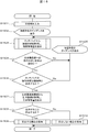
- FIG. 10 is an example of a flowchart showing the processing procedure of the registration processing of the user of the biometric registration / authentication system 1000 according to this embodiment. Each step of the registration process will be described below with reference to FIG.
- step S1001 the information input unit 107 receives an input of ID information identifying a user.
- step S1002 the information input unit 103 receives input of information on the type of living body to be registered.
- information on the type of living body to be registered For example, in the case of finger vein pattern authentication, “right hand middle finger”, “left hand index finger”, and the like are information for identifying a finger.
- step S1003 the user registration control unit 102 causes the information display unit 106 to display an operation guidance for biometric registration for the user.
- the content of the guidance to be displayed is an appropriate content according to the type of living body input in step S1002. For example, when the information input in step S1002 is “right middle finger”, guidance is displayed to hold the right middle finger over the living body imaging unit 104 as in the example illustrated in FIG. By displaying such guidance, the user can correctly recognize the living body to be registered.
- step S1004 contact information of a living body is acquired from the touch pad 105, and a contact feature amount is extracted from the acquired contact information. That is, the processing of the flowchart shown in FIG. 5 is executed.
- step S1005 the user registration control unit 102 determines whether the living body is appropriately held up with respect to the living body imaging unit 104 based on the contact feature amount acquired in step S1004, and the living body is: In step S1002, it is determined whether or not the type matches the living body type. An example of the determination is as shown in FIGS. 4 to 9, and it is determined, for example, whether or not the pattern of the standard touch feature amount as shown in FIG. 6 is obtained.
- step S1005 If it is determined in step S1005 that the living body is not properly held up with respect to the living body imaging unit 104 (step S1005; No), the user registration control unit 102 instructs the user in step S1006.
- the guidance is displayed to instruct correction of the holding state of the living body, and the process is re-executed from step S1004. By displaying such guidance, the user can make the holding condition of the living body appropriate.
- FIG. 12 An example of correction instruction guidance display is shown in FIG. FIG. 12 is an example of guidance for instructing the user to correct the living body when it is determined that the living body is floating. In addition to the example of the guidance illustrated in FIG. 12, it is determined that a finger different from the instruction for correcting the positional deviation of the living body in the vertical and horizontal directions or the type of the living body input in step S1002 is held by the living body imaging unit 104. When it is done, various guidance displays can be considered, such as giving corrective instructions to hold the correct finger.
- step S1005 If it is determined in step S1005 that the living body is appropriately held up with respect to the living body imaging unit 104 (step S1005; Yes), the user registration control unit 102 selects the living body imaging unit in step S1007.
- the biological information of the user is acquired from the user 104 and the biological feature is extracted from the biological information. Since the process of this step is executed only when it is determined in step S1005 that the holding state is appropriate, the accuracy at the time of authentication can be improved.
- step S1008 the user registration control unit 102 stores the user data acquired in the above steps in the user information storage unit 108.
- An example of user data is shown in FIG. Details will be described later.
- the information input unit 103 that receives an input of the type of living body may be input using a keyboard or the like, or the touch panel 110 is adopted, and in the case of finger vein pattern authentication, left and right hand images are displayed on the touch panel 110 , You may input by touching the finger which it is going to register.
- FIG. 13 shows an example of registration data.
- the registration data to be stored includes information such as the ID information of the user acquired in the registration process, the type of living body, the contact feature amount, and the biometric feature amount.
- the number of living bodies to be registered is not limited to one. For example, a plurality of living bodies, such as the right index finger and the right middle finger, may be registered. At that time, the type of the living body, the contact feature amount, and the biological feature amount are registered in each living body.
- information required at the time of biometric authentication transaction such as the user's name and age may be registered together. In the example shown in FIG.
- the user is identified by the ID information "00001234", and the living body registered in the present system is indicated to be the index finger of the right hand. Further, as contact features, histogram information at the time of longitudinal scanning and lateral scanning, five centroids and respective barycentric coordinates are registered, and it is indicated that biological feature quantities of the right index finger are registered. By storing such registration data, it is possible to easily grasp the user, and since it has histogram information, it is possible to grasp even the holding state of the living body by the user.
- FIG. 14 is an example of a flowchart showing the processing procedure of the authentication processing of the user of the biometric registration / authentication system 1000 in the present embodiment. Each step of the authentication process will be described below with reference to FIG.
- step S1401 the information input unit 107 receives an input of ID information identifying a user.
- the user authentication process shown in the subsequent steps authenticates whether the user using the authentication process of FIG. 14 is the registered user himself who is linked with the ID input in step S1401. It is for.
- step S1402 the information display unit 106 displays an operation guidance of biometric authentication to the user.
- the content of the guidance to be displayed is, as in the case of the biometric registration, an appropriate content according to the type of living body to be biometrically authenticated.
- the information display unit 106 displays guidance such that the middle finger of the right hand is held over the living body imaging unit 104 as in the example illustrated in FIG.
- one user is selected from certain living body types stored in advance as registration data of the user in a certain rule or at random. May be selected arbitrarily.
- step S1403 the user authentication control unit 103 acquires contact information of a living body from the touch pad 105, and extracts a contact feature amount from the acquired contact information. That is, the processing of the flowchart shown in FIG. 5 is executed.
- step S1404 the user authentication control unit 103 determines whether the living body is appropriately held up with respect to the living body imaging unit 104 based on the contact feature amount acquired in step S1403, and the living body is: It is determined in step S1402 whether or not the type of the specified living body matches. An example of the determination is as shown in FIGS. 4 to 9, and it is determined, for example, whether or not the pattern of the standard touch feature amount as shown in FIG. 6 is obtained. Further, in this step, the user authentication control unit 103 determines that the user has appropriately held up in the past and determines the similarity with the registered touch feature amount, and if the similarity is equal to or more than a threshold, the living body is It may be determined that the camera is properly held. In this case, the determination of the touch feature can be simplified, and the registration process can be performed more quickly.
- step S1404 If it is determined in step S1404 that the living body is not properly held up with respect to the living body imaging unit 104 (step S1404; No), the user authentication control unit 103 causes the user to receive the request in step S1405. The guidance is displayed to instruct correction of the holding state of the living body, and the process is re-executed from step S1403. An example of correction instruction guidance display is shown in FIG.
- a finger that is different from the type of biological body instructed in step S1402 or an instruction to correct positional deviations of the biological body in the vertical and horizontal directions is held over the biological imaging unit 104. If it is determined that the user has been instructed, various guidance displays can be considered, such as instructing correction to hold the correct finger.
- step S1404 If it is determined in step S1404 that the living body is appropriately held up with respect to the living body imaging unit 104 (step S1404; Yes), the user authentication control unit 103 performs the living body imaging unit in step S1406.
- the biological information of the user is acquired from the user 104 and the biological feature is extracted from the biological information.
- step S1407 the user authentication control unit 103 uses the biometric feature acquired in step S1406 and the use of the ID information specified in step S1401 among the users stored in the user information storage unit 108. Compare with the person's biometric feature. If the similarity is greater than or equal to a certain threshold, it is determined that the user is the user, and if it is less than the threshold, it is determined that the user is not the user. Since the process of this step is executed only when it is determined in step S 1404 that the user is in the appropriate holding state, the user can be accurately authenticated.
- step S1408 the user authentication control unit 103 performs processing in the case where the user is determined to be the user. For example, when the present biometric registration and authentication system is incorporated into a financial transaction system, processing of financial transactions etc. is executed.
- step S1407 If it is determined in step S1407 that the user is not the user (step S1407; No), then in step S1409, the user authentication control unit 103 performs processing in the case where the user is not determined to be the user. .
- the user authentication control unit 103 performs processing in the case where the user is not determined to be the user.
- transaction rejection processing in financial transactions is executed.
- the above is the processing procedure of the authentication processing in the present embodiment.
- the description of the retry process when the process fails, the interruption of the process when the number of retries reaches the upper limit, the interruption of the process due to timeout, etc. is omitted.
- the configuration and operation of the biometric registration / authentication system 1000 in the present embodiment have been described above. By performing each process described above, it is possible to reduce authentication failure due to various actions that disperse the holding state of the living body, as compared to the prior art, even when it is due to the user's intention or fault.
- FIG. 15 shows an example of the authentication process of the biometric registration / authentication system 1000 in this embodiment. Each step of the authentication process will be described below with reference to FIG.
- the processes in steps S1501 to S1505 are the same as the processes in steps S1401 to S1405 of the user authentication process in the first embodiment, and thus the description thereof will be omitted.
- step S1504 If it is determined in step S1504 that the living body is appropriately held up with respect to the living body imaging unit 104 (step S1504; Yes), the user authentication control unit 103 further performs step S1503 in step S1506.
- the contact feature amount acquired in step S104 is compared with the contact feature amount of the user identified by the ID information designated in step S1501 among the users stored in the user information storage unit 108. If the similarity does not reach a certain threshold, the user authentication control unit 103 determines that the difference in the holding state of the living body at the time of user registration and at the time of user authentication exceeds the allowable range, and step S1505
- the guidance is displayed to instruct the user to correct the holding state of the living body, and the process is re-executed from step S1503.
- step S1506 if the similarity exceeds a certain threshold (step S1506; Yes), it is determined that the difference in the holding state of the living body between user registration and user authentication is within the allowable range, The process advances to step S1507. Since the processes of steps S1507 to S1510 are the same as the processes of steps S1406 to S1409 of the user authentication process in the first embodiment, the description will be omitted.
- the above is the processing procedure of the authentication processing in the present embodiment. Compared with the authentication process of the user in the first embodiment, by adding the determination as to whether or not the touch information on the touch pad is similar at registration and at authentication, the user is authenticated with higher accuracy. be able to.
- a third embodiment of the present invention will be described with reference to FIG.
- the configuration of this embodiment, the user registration process, and the user authentication process are the same as in the first embodiment or the second embodiment, and thus the description thereof is omitted.
- FIG. 16 is a perspective view of another arrangement example of the living body imaging unit 104 and the touch pad 105 when it is assumed that a finger vein pattern is used as living body information.
- the living body imaging unit 104 is attachable to and detachable from the palm rest 204, and is attached and detached along the attachment and detachment guide 1601.
- the palm rest 204 can be attached to the living body imaging unit 104 and operated only when necessary, for example, when there is not a sufficient space for installing the palm rest 204, such as on a narrow desk.
- a data communication cable 1604 separate from the data communication cable 203 is prepared as data communication means for the touch pad 105 with the outside, and data communication is performed via the data communication cable, and the living body imaging unit 104 and palm rest main body 204
- a pair of connectors 1602 and 1603 coupled together may be prepared, and data communication may be performed via them and the data communication cable 203.
- the connector 1602 and the data communication cable 203 are logically coupled. Further, either one of the pair of connectors 1602 and 1603 and the data communication cable 1604 may be provided.
- a fourth embodiment of the present invention will be described with reference to FIG.
- the configuration of this embodiment, the user registration process, and the user authentication process are the same as in the first embodiment or the second embodiment, and thus the description thereof is omitted.
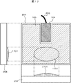
- FIG. 17 is a three-sided view of another arrangement example of the living body imaging unit 104 and the touch pad 105 when it is assumed that a finger vein pattern is used as living body information.
- an elliptic curved bulge 1701 is provided in the illustrated portion of the palm rest 204.
- the position of the elliptical bulge 1701 assumes the position of the palm when holding the finger over the living body imaging unit 104, and when the finger is held over the living body imaging unit 104, the elliptical bulge 1701 contacts the palm. By supporting, it can be expected to reduce the movement of the living body and the oblique placement.
- the surface portion of the elliptical bulge 1701 also has a touch pad function as the touch pad 105 does.
- the state of contact of the living body with the elliptical bulge 1701 is monitored independently of the touch pad 105, as shown in step S1004 in FIG. 10 and in FIG. As shown in FIG. 13 including checking of the contact state and contact area of the living body with respect to the elliptic bulge 1701 or the histogram when determining whether the finger holding state to the living body imaging unit 104 is appropriate or not in step S1404. By adding the check to the same information as the registered data, it is possible to expect improvement in the accuracy of judgment whether the finger holding state to the living body imaging unit 104 is appropriate.
- the living body imaging unit 104 and the palm rest 204 may be removable as in the third embodiment.
- the touch pad 105 instead of providing an elliptical bulge 1701 on the surface portion, the entire bulge or rounded ridge as shown in FIG. 18 is formed along the shape of the entire palm. It may be a mold or a mouse.
- a technique for applying a curved surface to the touch pad 105 it is possible to use a conventionally known technique. In this case, the registration process and the authentication process can be performed in a natural state when the user places a hand on the palm rest 105.
- a combination with the above-described elliptical bulge 1701 is also possible.
- the configuration and operation of the biometric registration and authentication system in the present embodiment have been described above.
- step S1504 it is determined in step S1504 whether the holding state to the living body imaging unit is appropriate or not. It is determined that the user tends to hold the living body properly, and this step may be omitted in the next authentication process. In this case, biometric authentication can be performed promptly, and a check can be made only for users who tend not to properly hold the living body.
- the position, shape, and size of the living body imaging unit 104 and the touch pad 105 can be appropriately changed according to the number of living bodies to be registered / authenticated, and the like.
- the touch pad 105 is disposed on the palm rest 204.
- the palm rest 204 may not be disposed on the touch pad 105, and may be similar to the first to fourth embodiments.
- the configurations may be combined as appropriate.
- the extraction process of the contact feature amount step S1004 of FIG. 10, step S1403 of FIG. 14, step S1503 of FIG. 15
- the determination process step S1005 in FIG. 10, step S1404 in FIG. 14, step S1504 in FIG. 15 of determining whether there is any is omitted.
- the palm rest 204 can be attached to the living body imaging unit 104 and operated only when necessary. For example, based on an imaging unit for imaging a first living body of a living body used for registration or authentication, the captured image of the first living body, and a registered image of the first living body stored in advance in a storage unit. And a control unit for registering or authenticating the user, and a second living body other than the first living body, which is detachable from the living body registration / authentication device And a palm rest, and may be configured as a biometric registration and authentication system.
- the touch pad 105 is not disposed on the palm rest 204, and as described with reference to FIG. 4, the living body imaging unit 104 also aligns the function of the touch pad 105 and contacts the portion displayed as the noncontact portion 402.
- the extraction process and the determination process are performed on the portion.
- the contact feature value is acquired for the first living body, and the accuracy of registration and authentication of the holding state of the living body is maintained to a certain extent, and the present system can be realized with a simple configuration for the palm rest 204. it can.
- the palm rest 204 can be attached to the living body imaging unit 104 and operated only when necessary.
- the finger vein pattern is used as the biological information in the above-mentioned embodiment, other biological information such as fingerprints, vein patterns of the palm, etc. use biological information whose characteristics are different in each individual. It can also be done.
- the finger vein pattern may be combined with different biometric information such as voice print and iris pattern, or may be used in combination with other authentication means such as a personal identification number.
- Each of the components such as the configuration, functions, processing unit, and processing means of the present system may be realized by hardware, for example, by designing part or all of them with an integrated circuit. Further, each configuration, function, etc. described above may be realized by software by the processor interpreting and executing a program that realizes each function. Information such as a program, a table, and a file for realizing each function can be placed in a memory, a hard disk, a recording device such as a solid state drive (SSD), or a recording medium such as an IC card, an SD card, or a DVD. Further, control lines and information lines indicate what is considered to be necessary for the description, and not all control lines and information lines in the product are necessarily shown. In practice, almost all configurations may be considered to be mutually connected.
- SSD solid state drive
Landscapes
- Health & Medical Sciences (AREA)
- Life Sciences & Earth Sciences (AREA)
- Engineering & Computer Science (AREA)
- Physics & Mathematics (AREA)
- Surgery (AREA)
- Animal Behavior & Ethology (AREA)
- Biomedical Technology (AREA)
- Heart & Thoracic Surgery (AREA)
- Medical Informatics (AREA)
- Molecular Biology (AREA)
- Biophysics (AREA)
- Pathology (AREA)
- General Health & Medical Sciences (AREA)
- Public Health (AREA)
- Veterinary Medicine (AREA)
- General Physics & Mathematics (AREA)
- Business, Economics & Management (AREA)
- Computer Security & Cryptography (AREA)
- Theoretical Computer Science (AREA)
- Accounting & Taxation (AREA)
- Dentistry (AREA)
- Physiology (AREA)
- Software Systems (AREA)
- Computer Hardware Design (AREA)
- Vascular Medicine (AREA)
- Human Computer Interaction (AREA)
- Oral & Maxillofacial Surgery (AREA)
- General Engineering & Computer Science (AREA)
- Finance (AREA)
- Strategic Management (AREA)
- General Business, Economics & Management (AREA)
- Measurement Of The Respiration, Hearing Ability, Form, And Blood Characteristics Of Living Organisms (AREA)
- Collating Specific Patterns (AREA)
- Image Input (AREA)
Abstract
Priority Applications (2)
| Application Number | Priority Date | Filing Date | Title |
|---|---|---|---|
| PCT/JP2014/057882 WO2015141007A1 (fr) | 2014-03-20 | 2014-03-20 | Système d'enregistrement/authentification biométrique et procédé d'enregistrement/authentification biométrique |
| JP2016508432A JP6035452B2 (ja) | 2014-03-20 | 2014-03-20 | 生体登録・認証システムおよび生体登録・認証方法 |
Applications Claiming Priority (1)
| Application Number | Priority Date | Filing Date | Title |
|---|---|---|---|
| PCT/JP2014/057882 WO2015141007A1 (fr) | 2014-03-20 | 2014-03-20 | Système d'enregistrement/authentification biométrique et procédé d'enregistrement/authentification biométrique |
Publications (1)
| Publication Number | Publication Date |
|---|---|
| WO2015141007A1 true WO2015141007A1 (fr) | 2015-09-24 |
Family
ID=54144007
Family Applications (1)
| Application Number | Title | Priority Date | Filing Date |
|---|---|---|---|
| PCT/JP2014/057882 WO2015141007A1 (fr) | 2014-03-20 | 2014-03-20 | Système d'enregistrement/authentification biométrique et procédé d'enregistrement/authentification biométrique |
Country Status (2)
| Country | Link |
|---|---|
| JP (1) | JP6035452B2 (fr) |
| WO (1) | WO2015141007A1 (fr) |
Cited By (2)
| Publication number | Priority date | Publication date | Assignee | Title |
|---|---|---|---|---|
| WO2017104061A1 (fr) * | 2015-12-18 | 2017-06-22 | 株式会社日立製作所 | Dispositif et système d'authentification biométrique |
| CN114373257A (zh) * | 2021-12-21 | 2022-04-19 | 日立楼宇技术(广州)有限公司 | 用于访客召梯的卡片、召梯系统、方法及装置 |
Citations (8)
| Publication number | Priority date | Publication date | Assignee | Title |
|---|---|---|---|---|
| JPH11144058A (ja) * | 1997-06-10 | 1999-05-28 | Internatl Business Mach Corp <Ibm> | バイオメトリック画像の合格度を確保するシステムおよび方法 |
| JP2006331239A (ja) * | 2005-05-30 | 2006-12-07 | Hitachi Omron Terminal Solutions Corp | 個人認証装置および個人認証システム |
| US20080092245A1 (en) * | 2006-09-15 | 2008-04-17 | Agent Science Technologies, Inc. | Multi-touch device behaviormetric user authentication and dynamic usability system |
| US20080265024A1 (en) * | 2007-04-30 | 2008-10-30 | Tracy Mark S | Electronic device with functional module |
| JP2011253438A (ja) * | 2010-06-03 | 2011-12-15 | Hitachi Omron Terminal Solutions Corp | 生体認証ユニット |
| WO2013046365A1 (fr) * | 2011-09-28 | 2013-04-04 | 富士通フロンテック株式会社 | Dispositif de guidage, dispositif d'acquisition d'informations biométriques et dispositif d'enregistrement |
| JP2013205931A (ja) * | 2012-03-27 | 2013-10-07 | Fujitsu Ltd | 生体情報取得装置、生体情報取得方法、生体情報取得制御プログラム |
| JP2014026585A (ja) * | 2012-07-30 | 2014-02-06 | Fujitsu Frontech Ltd | 生体情報入力装置、生体支持状態判定方法、および生体支持状態判定プログラム |
-
2014
- 2014-03-20 JP JP2016508432A patent/JP6035452B2/ja not_active Expired - Fee Related
- 2014-03-20 WO PCT/JP2014/057882 patent/WO2015141007A1/fr active Application Filing
Patent Citations (8)
| Publication number | Priority date | Publication date | Assignee | Title |
|---|---|---|---|---|
| JPH11144058A (ja) * | 1997-06-10 | 1999-05-28 | Internatl Business Mach Corp <Ibm> | バイオメトリック画像の合格度を確保するシステムおよび方法 |
| JP2006331239A (ja) * | 2005-05-30 | 2006-12-07 | Hitachi Omron Terminal Solutions Corp | 個人認証装置および個人認証システム |
| US20080092245A1 (en) * | 2006-09-15 | 2008-04-17 | Agent Science Technologies, Inc. | Multi-touch device behaviormetric user authentication and dynamic usability system |
| US20080265024A1 (en) * | 2007-04-30 | 2008-10-30 | Tracy Mark S | Electronic device with functional module |
| JP2011253438A (ja) * | 2010-06-03 | 2011-12-15 | Hitachi Omron Terminal Solutions Corp | 生体認証ユニット |
| WO2013046365A1 (fr) * | 2011-09-28 | 2013-04-04 | 富士通フロンテック株式会社 | Dispositif de guidage, dispositif d'acquisition d'informations biométriques et dispositif d'enregistrement |
| JP2013205931A (ja) * | 2012-03-27 | 2013-10-07 | Fujitsu Ltd | 生体情報取得装置、生体情報取得方法、生体情報取得制御プログラム |
| JP2014026585A (ja) * | 2012-07-30 | 2014-02-06 | Fujitsu Frontech Ltd | 生体情報入力装置、生体支持状態判定方法、および生体支持状態判定プログラム |
Cited By (6)
| Publication number | Priority date | Publication date | Assignee | Title |
|---|---|---|---|---|
| WO2017104061A1 (fr) * | 2015-12-18 | 2017-06-22 | 株式会社日立製作所 | Dispositif et système d'authentification biométrique |
| JPWO2017104061A1 (ja) * | 2015-12-18 | 2018-05-10 | 株式会社日立製作所 | 生体認証装置およびシステム |
| EP3392824A4 (fr) * | 2015-12-18 | 2019-10-23 | Hitachi, Ltd. | Dispositif et système d'authentification biométrique |
| US10460187B2 (en) | 2015-12-18 | 2019-10-29 | Hitachi, Ltd. | Biometric authentication device and system |
| CN114373257A (zh) * | 2021-12-21 | 2022-04-19 | 日立楼宇技术(广州)有限公司 | 用于访客召梯的卡片、召梯系统、方法及装置 |
| CN114373257B (zh) * | 2021-12-21 | 2023-06-20 | 日立楼宇技术(广州)有限公司 | 用于访客召梯的卡片、召梯系统、方法及装置 |
Also Published As
| Publication number | Publication date |
|---|---|
| JPWO2015141007A1 (ja) | 2017-04-06 |
| JP6035452B2 (ja) | 2016-11-30 |
Similar Documents
| Publication | Publication Date | Title |
|---|---|---|
| CN106897592B (zh) | 用户认证方法、用户认证设备以及书写工具 | |
| TWI533230B (zh) | 使用生物運動輸入的使用者識別 | |
| US9280281B2 (en) | System and method for providing gesture-based user identification | |
| US8661516B2 (en) | Biometric authentication device and biometric authentication method | |
| JP5213908B2 (ja) | 生体認証ユニット | |
| EP2833319B1 (fr) | Dispositif d'authentification biométrique, procédé d'authentification biométrique, et programme informatique d'authentification biométrique | |
| JP5851209B2 (ja) | 生体認証装置およびそれを備えた自動取引装置 | |
| US10586031B2 (en) | Biometric authentication of a user | |
| JP2010146073A (ja) | 生体認証装置、生体認証方法及び生体認証用コンピュータプログラムならびにコンピュータシステム | |
| EP3336756A1 (fr) | Dispositif de traitement d'images, procédé de traitement d'images et programme de traitement d'images | |
| US20160048718A1 (en) | Enhanced kinematic signature authentication using embedded fingerprint image array | |
| JP6160148B2 (ja) | 生体情報入力装置、生体情報入力プログラム、生体情報入力方法 | |
| JP5915336B2 (ja) | 生体認証装置、生体認証方法及び生体認証用コンピュータプログラム | |
| EP3223193B1 (fr) | Dispositif de traitement d'images, procédé de traitement d'images et programme de traitement d'images | |
| JP6272069B2 (ja) | 情報処理装置、情報処理方法、コンピュータプログラム、及び記録媒体 | |
| WO2015141007A1 (fr) | Système d'enregistrement/authentification biométrique et procédé d'enregistrement/authentification biométrique | |
| WO2021001322A1 (fr) | Segmentation par division forcée d'images d'empreintes digitales sans contact | |
| CN108596127B (zh) | 一种指纹识别方法、身份验证方法及装置和身份核验机 | |
| EP3330888A1 (fr) | Appareil d'authentification biométrique, système d'authentification biométrique et programme d'authentification biométrique | |
| JP6364828B2 (ja) | 生体認証装置および携帯型電子装置 | |
| JP2017091276A (ja) | 操作許可判定装置、操作許可判定システム、操作許可判定方法、及び操作許可判定用プログラム | |
| JP6795677B2 (ja) | 生体認証プログラム、生体認証装置および生体認証方法 | |
| TWI576717B (zh) | Dimensional biometric identification system and method | |
| WO2018163531A1 (fr) | Dispositif d'authentification et procédé de commande correspondant, système de verrouillage de porte et programme | |
| JP2023011333A (ja) | 情報処理装置及び情報処理方法 |
Legal Events
| Date | Code | Title | Description |
|---|---|---|---|
| 121 | Ep: the epo has been informed by wipo that ep was designated in this application |
Ref document number: 14886665 Country of ref document: EP Kind code of ref document: A1 |
|
| ENP | Entry into the national phase |
Ref document number: 2016508432 Country of ref document: JP Kind code of ref document: A |
|
| WWE | Wipo information: entry into national phase |
Ref document number: 417570 Country of ref document: PL |
|
| NENP | Non-entry into the national phase |
Ref country code: DE |
|
| 122 | Ep: pct application non-entry in european phase |
Ref document number: 14886665 Country of ref document: EP Kind code of ref document: A1 |