WO2015140832A1 - Permanent magnet, motor and generator - Google Patents
Permanent magnet, motor and generator Download PDFInfo
- Publication number
- WO2015140832A1 WO2015140832A1 PCT/JP2014/001581 JP2014001581W WO2015140832A1 WO 2015140832 A1 WO2015140832 A1 WO 2015140832A1 JP 2014001581 W JP2014001581 W JP 2014001581W WO 2015140832 A1 WO2015140832 A1 WO 2015140832A1
- Authority
- WO
- WIPO (PCT)
- Prior art keywords
- phase
- atomic
- permanent magnet
- concentration
- hours
- Prior art date
Links
Images


Classifications
-
- H—ELECTRICITY
- H01—ELECTRIC ELEMENTS
- H01F—MAGNETS; INDUCTANCES; TRANSFORMERS; SELECTION OF MATERIALS FOR THEIR MAGNETIC PROPERTIES
- H01F1/00—Magnets or magnetic bodies characterised by the magnetic materials therefor; Selection of materials for their magnetic properties
- H01F1/01—Magnets or magnetic bodies characterised by the magnetic materials therefor; Selection of materials for their magnetic properties of inorganic materials
- H01F1/03—Magnets or magnetic bodies characterised by the magnetic materials therefor; Selection of materials for their magnetic properties of inorganic materials characterised by their coercivity
- H01F1/032—Magnets or magnetic bodies characterised by the magnetic materials therefor; Selection of materials for their magnetic properties of inorganic materials characterised by their coercivity of hard-magnetic materials
- H01F1/04—Magnets or magnetic bodies characterised by the magnetic materials therefor; Selection of materials for their magnetic properties of inorganic materials characterised by their coercivity of hard-magnetic materials metals or alloys
- H01F1/047—Alloys characterised by their composition
- H01F1/053—Alloys characterised by their composition containing rare earth metals
- H01F1/055—Alloys characterised by their composition containing rare earth metals and magnetic transition metals, e.g. SmCo5
-
- C—CHEMISTRY; METALLURGY
- C22—METALLURGY; FERROUS OR NON-FERROUS ALLOYS; TREATMENT OF ALLOYS OR NON-FERROUS METALS
- C22C—ALLOYS
- C22C1/00—Making non-ferrous alloys
- C22C1/04—Making non-ferrous alloys by powder metallurgy
- C22C1/0433—Nickel- or cobalt-based alloys
- C22C1/0441—Alloys based on intermetallic compounds of the type rare earth - Co, Ni
-
- C—CHEMISTRY; METALLURGY
- C22—METALLURGY; FERROUS OR NON-FERROUS ALLOYS; TREATMENT OF ALLOYS OR NON-FERROUS METALS
- C22C—ALLOYS
- C22C19/00—Alloys based on nickel or cobalt
- C22C19/07—Alloys based on nickel or cobalt based on cobalt
-
- C—CHEMISTRY; METALLURGY
- C22—METALLURGY; FERROUS OR NON-FERROUS ALLOYS; TREATMENT OF ALLOYS OR NON-FERROUS METALS
- C22C—ALLOYS
- C22C30/00—Alloys containing less than 50% by weight of each constituent
- C22C30/02—Alloys containing less than 50% by weight of each constituent containing copper
-
- C—CHEMISTRY; METALLURGY
- C22—METALLURGY; FERROUS OR NON-FERROUS ALLOYS; TREATMENT OF ALLOYS OR NON-FERROUS METALS
- C22F—CHANGING THE PHYSICAL STRUCTURE OF NON-FERROUS METALS AND NON-FERROUS ALLOYS
- C22F1/00—Changing the physical structure of non-ferrous metals or alloys by heat treatment or by hot or cold working
- C22F1/10—Changing the physical structure of non-ferrous metals or alloys by heat treatment or by hot or cold working of nickel or cobalt or alloys based thereon
-
- H—ELECTRICITY
- H01—ELECTRIC ELEMENTS
- H01F—MAGNETS; INDUCTANCES; TRANSFORMERS; SELECTION OF MATERIALS FOR THEIR MAGNETIC PROPERTIES
- H01F1/00—Magnets or magnetic bodies characterised by the magnetic materials therefor; Selection of materials for their magnetic properties
- H01F1/01—Magnets or magnetic bodies characterised by the magnetic materials therefor; Selection of materials for their magnetic properties of inorganic materials
- H01F1/03—Magnets or magnetic bodies characterised by the magnetic materials therefor; Selection of materials for their magnetic properties of inorganic materials characterised by their coercivity
- H01F1/032—Magnets or magnetic bodies characterised by the magnetic materials therefor; Selection of materials for their magnetic properties of inorganic materials characterised by their coercivity of hard-magnetic materials
- H01F1/04—Magnets or magnetic bodies characterised by the magnetic materials therefor; Selection of materials for their magnetic properties of inorganic materials characterised by their coercivity of hard-magnetic materials metals or alloys
- H01F1/047—Alloys characterised by their composition
- H01F1/053—Alloys characterised by their composition containing rare earth metals
- H01F1/0536—Alloys characterised by their composition containing rare earth metals sintered
-
- H—ELECTRICITY
- H01—ELECTRIC ELEMENTS
- H01F—MAGNETS; INDUCTANCES; TRANSFORMERS; SELECTION OF MATERIALS FOR THEIR MAGNETIC PROPERTIES
- H01F1/00—Magnets or magnetic bodies characterised by the magnetic materials therefor; Selection of materials for their magnetic properties
- H01F1/01—Magnets or magnetic bodies characterised by the magnetic materials therefor; Selection of materials for their magnetic properties of inorganic materials
- H01F1/03—Magnets or magnetic bodies characterised by the magnetic materials therefor; Selection of materials for their magnetic properties of inorganic materials characterised by their coercivity
- H01F1/032—Magnets or magnetic bodies characterised by the magnetic materials therefor; Selection of materials for their magnetic properties of inorganic materials characterised by their coercivity of hard-magnetic materials
- H01F1/04—Magnets or magnetic bodies characterised by the magnetic materials therefor; Selection of materials for their magnetic properties of inorganic materials characterised by their coercivity of hard-magnetic materials metals or alloys
- H01F1/047—Alloys characterised by their composition
- H01F1/053—Alloys characterised by their composition containing rare earth metals
- H01F1/055—Alloys characterised by their composition containing rare earth metals and magnetic transition metals, e.g. SmCo5
- H01F1/0555—Alloys characterised by their composition containing rare earth metals and magnetic transition metals, e.g. SmCo5 pressed, sintered or bonded together
- H01F1/0557—Alloys characterised by their composition containing rare earth metals and magnetic transition metals, e.g. SmCo5 pressed, sintered or bonded together sintered
-
- H—ELECTRICITY
- H02—GENERATION; CONVERSION OR DISTRIBUTION OF ELECTRIC POWER
- H02K—DYNAMO-ELECTRIC MACHINES
- H02K1/00—Details of the magnetic circuit
- H02K1/02—Details of the magnetic circuit characterised by the magnetic material
-
- H—ELECTRICITY
- H02—GENERATION; CONVERSION OR DISTRIBUTION OF ELECTRIC POWER
- H02K—DYNAMO-ELECTRIC MACHINES
- H02K1/00—Details of the magnetic circuit
- H02K1/06—Details of the magnetic circuit characterised by the shape, form or construction
- H02K1/22—Rotating parts of the magnetic circuit
- H02K1/27—Rotor cores with permanent magnets
- H02K1/2706—Inner rotors
- H02K1/272—Inner rotors the magnetisation axis of the magnets being perpendicular to the rotor axis
- H02K1/274—Inner rotors the magnetisation axis of the magnets being perpendicular to the rotor axis the rotor consisting of two or more circumferentially positioned magnets
- H02K1/2753—Inner rotors the magnetisation axis of the magnets being perpendicular to the rotor axis the rotor consisting of two or more circumferentially positioned magnets the rotor consisting of magnets or groups of magnets arranged with alternating polarity
- H02K1/276—Magnets embedded in the magnetic core, e.g. interior permanent magnets [IPM]
- H02K1/2766—Magnets embedded in the magnetic core, e.g. interior permanent magnets [IPM] having a flux concentration effect
-
- B—PERFORMING OPERATIONS; TRANSPORTING
- B22—CASTING; POWDER METALLURGY
- B22F—WORKING METALLIC POWDER; MANUFACTURE OF ARTICLES FROM METALLIC POWDER; MAKING METALLIC POWDER; APPARATUS OR DEVICES SPECIALLY ADAPTED FOR METALLIC POWDER
- B22F9/00—Making metallic powder or suspensions thereof
- B22F9/02—Making metallic powder or suspensions thereof using physical processes
- B22F9/04—Making metallic powder or suspensions thereof using physical processes starting from solid material, e.g. by crushing, grinding or milling
- B22F2009/041—Making metallic powder or suspensions thereof using physical processes starting from solid material, e.g. by crushing, grinding or milling by mechanical alloying, e.g. blending, milling
-
- B—PERFORMING OPERATIONS; TRANSPORTING
- B22—CASTING; POWDER METALLURGY
- B22F—WORKING METALLIC POWDER; MANUFACTURE OF ARTICLES FROM METALLIC POWDER; MAKING METALLIC POWDER; APPARATUS OR DEVICES SPECIALLY ADAPTED FOR METALLIC POWDER
- B22F9/00—Making metallic powder or suspensions thereof
- B22F9/02—Making metallic powder or suspensions thereof using physical processes
- B22F9/04—Making metallic powder or suspensions thereof using physical processes starting from solid material, e.g. by crushing, grinding or milling
- B22F2009/043—Making metallic powder or suspensions thereof using physical processes starting from solid material, e.g. by crushing, grinding or milling by ball milling
-
- B—PERFORMING OPERATIONS; TRANSPORTING
- B22—CASTING; POWDER METALLURGY
- B22F—WORKING METALLIC POWDER; MANUFACTURE OF ARTICLES FROM METALLIC POWDER; MAKING METALLIC POWDER; APPARATUS OR DEVICES SPECIALLY ADAPTED FOR METALLIC POWDER
- B22F9/00—Making metallic powder or suspensions thereof
- B22F9/02—Making metallic powder or suspensions thereof using physical processes
- B22F9/04—Making metallic powder or suspensions thereof using physical processes starting from solid material, e.g. by crushing, grinding or milling
- B22F2009/044—Making metallic powder or suspensions thereof using physical processes starting from solid material, e.g. by crushing, grinding or milling by jet milling
-
- B—PERFORMING OPERATIONS; TRANSPORTING
- B22—CASTING; POWDER METALLURGY
- B22F—WORKING METALLIC POWDER; MANUFACTURE OF ARTICLES FROM METALLIC POWDER; MAKING METALLIC POWDER; APPARATUS OR DEVICES SPECIALLY ADAPTED FOR METALLIC POWDER
- B22F9/00—Making metallic powder or suspensions thereof
- B22F9/02—Making metallic powder or suspensions thereof using physical processes
- B22F9/04—Making metallic powder or suspensions thereof using physical processes starting from solid material, e.g. by crushing, grinding or milling
- B22F2009/048—Making metallic powder or suspensions thereof using physical processes starting from solid material, e.g. by crushing, grinding or milling by pulverising a quenched ribbon
-
- B—PERFORMING OPERATIONS; TRANSPORTING
- B22—CASTING; POWDER METALLURGY
- B22F—WORKING METALLIC POWDER; MANUFACTURE OF ARTICLES FROM METALLIC POWDER; MAKING METALLIC POWDER; APPARATUS OR DEVICES SPECIALLY ADAPTED FOR METALLIC POWDER
- B22F2998/00—Supplementary information concerning processes or compositions relating to powder metallurgy
- B22F2998/10—Processes characterised by the sequence of their steps
-
- B—PERFORMING OPERATIONS; TRANSPORTING
- B22—CASTING; POWDER METALLURGY
- B22F—WORKING METALLIC POWDER; MANUFACTURE OF ARTICLES FROM METALLIC POWDER; MAKING METALLIC POWDER; APPARATUS OR DEVICES SPECIALLY ADAPTED FOR METALLIC POWDER
- B22F2999/00—Aspects linked to processes or compositions used in powder metallurgy
-
- B—PERFORMING OPERATIONS; TRANSPORTING
- B22—CASTING; POWDER METALLURGY
- B22F—WORKING METALLIC POWDER; MANUFACTURE OF ARTICLES FROM METALLIC POWDER; MAKING METALLIC POWDER; APPARATUS OR DEVICES SPECIALLY ADAPTED FOR METALLIC POWDER
- B22F9/00—Making metallic powder or suspensions thereof
- B22F9/02—Making metallic powder or suspensions thereof using physical processes
- B22F9/06—Making metallic powder or suspensions thereof using physical processes starting from liquid material
- B22F9/08—Making metallic powder or suspensions thereof using physical processes starting from liquid material by casting, e.g. through sieves or in water, by atomising or spraying
-
- H—ELECTRICITY
- H01—ELECTRIC ELEMENTS
- H01F—MAGNETS; INDUCTANCES; TRANSFORMERS; SELECTION OF MATERIALS FOR THEIR MAGNETIC PROPERTIES
- H01F1/00—Magnets or magnetic bodies characterised by the magnetic materials therefor; Selection of materials for their magnetic properties
- H01F1/01—Magnets or magnetic bodies characterised by the magnetic materials therefor; Selection of materials for their magnetic properties of inorganic materials
- H01F1/03—Magnets or magnetic bodies characterised by the magnetic materials therefor; Selection of materials for their magnetic properties of inorganic materials characterised by their coercivity
- H01F1/032—Magnets or magnetic bodies characterised by the magnetic materials therefor; Selection of materials for their magnetic properties of inorganic materials characterised by their coercivity of hard-magnetic materials
- H01F1/04—Magnets or magnetic bodies characterised by the magnetic materials therefor; Selection of materials for their magnetic properties of inorganic materials characterised by their coercivity of hard-magnetic materials metals or alloys
- H01F1/047—Alloys characterised by their composition
- H01F1/053—Alloys characterised by their composition containing rare earth metals
- H01F1/055—Alloys characterised by their composition containing rare earth metals and magnetic transition metals, e.g. SmCo5
- H01F1/059—Alloys characterised by their composition containing rare earth metals and magnetic transition metals, e.g. SmCo5 and Va elements, e.g. Sm2Fe17N2
- H01F1/0596—Alloys characterised by their composition containing rare earth metals and magnetic transition metals, e.g. SmCo5 and Va elements, e.g. Sm2Fe17N2 of rhombic or rhombohedral Th2Zn17 structure or hexagonal Th2Ni17 structure
Definitions
- the invention of the embodiments relates to a permanent magnet, a motor, and a generator.
- high-performance rare earth magnets Sm—Co magnets, Nd—Fe—B magnets, and the like are known.
- Fe and Co contribute to an increase in saturation magnetization.
- these magnets contain rare earth elements such as Nd and Sm, and bring about a large magnetic anisotropy due to the behavior of 4f electrons of the rare earth elements in the crystal field. Thereby, a large coercive force is obtained and a high-performance magnet is realized.
- Such high performance magnets are mainly used in electric devices such as motors, speakers, and measuring instruments.
- demands for reducing the size and weight of various electrical devices and reducing power consumption have increased, and in order to meet these demands, there has been a demand for higher performance permanent magnets that improve the maximum magnetic energy product (BHmax) of permanent magnets.
- BHmax maximum magnetic energy product
- a variable magnetic flux type motor has been proposed, which contributes to higher efficiency of the motor.
- Sm—Co magnets have a high Curie temperature, it is possible to achieve good motor characteristics at high temperatures. However, further enhancement of coercivity and magnetization, and improvement in squareness ratio are desired. It is considered that increasing the concentration of Fe is effective for increasing the magnetization of the Sm—Co-based magnet, but in the conventional manufacturing method, the squareness ratio tends to decrease by increasing the concentration of Fe. For this reason, in order to realize a magnet for a high-performance motor, a technique is required that enables the expression of a favorable squareness ratio while improving the magnetization at a high Fe concentration composition.
- the problem to be solved by the present invention is to provide a high-performance permanent magnet by controlling the metal structure of the Sm—Co magnet.
- the permanent magnet of the embodiment the composition formula: R p Fe q M r Cu t Co 100-p-q-r-t (wherein, at least one element R selected from rare earth elements, M is Zr, Ti And at least one element selected from the group consisting of Hf, p is a number satisfying 10.8 ⁇ p ⁇ 12.5 atomic%, q is a number satisfying 25 ⁇ q ⁇ 40 atomic%, and r is 0 A composition satisfying .88 ⁇ r ⁇ 4.5 atomic%, t is a number satisfying 3.5 ⁇ t ⁇ 13.5 atomic%) and a Th 2 Zn 17 type crystal phase. And a metal structure including a Cu—M rich phase having a higher Cu concentration and higher M concentration than the main phase. The diameter of the Cu-M rich phase is 10 ⁇ m or less.
- the permanent magnet of the embodiment the composition formula: R p Fe q M r Cu t Co 100-p-q-r-t (wherein, at least one element R selected from rare earth elements, M is Zr, Ti And at least one element selected from the group consisting of Hf, p is a number satisfying 10.8 ⁇ p ⁇ 12.5 atomic%, q is a number satisfying 25 ⁇ q ⁇ 40 atomic%, and r is 0 A composition satisfying .88 ⁇ r ⁇ 4.5 atomic%, t is a number satisfying 3.5 ⁇ t ⁇ 13.5 atomic%) and a Th 2 Zn 17 type crystal phase. And a metal structure including a grain boundary phase provided between crystal grains constituting the main phase.
- the grain boundary phase has a Cu—M rich phase having a higher Cu concentration and M concentration than the main phase, and the average grain size of the crystal grains constituting the main phase is 35 ⁇ m or more.
- Permanent magnet of this embodiment the composition formula: R p Fe q M r Cu t Co 100-p-q-r-t (Wherein R is at least one element selected from rare earth elements, M is at least one element selected from the group consisting of Zr, Ti, and Hf, and p is 10.8 ⁇ p ⁇ 12.5 atomic%.
- Q is a number satisfying 25 ⁇ q ⁇ 40 atomic%, r is a number satisfying 0.88 ⁇ r ⁇ 4.5 atomic%, and t is 3.5 ⁇ t ⁇ 13.5 atomic% Is a number satisfying the above).
- R in the above composition formula is an element that can bring a large magnetic anisotropy to the magnet material.
- the R element for example, one or more elements selected from rare earth elements including yttrium (Y) can be used.
- Y yttrium
- Sm samarium
- Ce cerium
- Nd neodymium
- Pr praseodymium
- the performance of the magnet material for example, the coercive force, can be increased by setting the Sm concentration to 50 atomic% or more of the total elements applicable as the R element. More preferably, 70 atomic% or more of the elements applicable as the R element is Sm.
- the coercive force can be increased by setting the concentration of the element applicable as the R element to, for example, 10.8 atomic% or more and 12.5 atomic% or less.
- concentration of the element applicable as the R element is less than 10.8 atomic%, a large amount of ⁇ -Fe is precipitated to reduce the coercive force, and the concentration of the element applicable as the R element is 12.5 atomic%.
- saturation magnetization falls.
- the concentration of the element applicable as the R element is more preferably 0.9 atomic% or more and 12.1 atomic% or less.
- M in the above composition formula is an element capable of expressing a large coercive force with a composition having a high Fe concentration.
- the M element for example, one or more elements selected from the group consisting of titanium (Ti), zirconium (Zr), and hafnium (Hf) are used.
- Ti titanium
- Zr zirconium
- Hf hafnium
- the content r of the M element exceeds 4.5 atomic%, a heterogeneous phase containing an excessive amount of the M element is likely to be generated, and both the coercive force and the magnetization are likely to be reduced.
- the content r of the M element is less than 0.88 atomic%, the effect of increasing the Fe concentration tends to be small.
- the content r of the M element is preferably 0.88 atomic% or more and 4.5 atomic% or less.
- the content r of the element M is more preferably 1.14 atomic% or more and 3.58 atomic% or less, and more preferably 1.49 atomic% or more and 2.24 atomic% or less.
- the M element preferably contains at least Zr.
- the coercive force of the permanent magnet can be increased by using 50 atomic% or more of the M element as Zr.
- the amount used is small even when Hf is used.
- the Hf content is preferably less than 20 atomic% of the M element.
- the Cu is an element that can exhibit a high coercive force in a magnet material.
- the Cu content is preferably, for example, 3.5 atomic% or more and 13.5 atomic% or less. When the amount is larger than this, the magnetization is remarkably lowered, and when the amount is smaller than this, it is difficult to obtain a high coercive force and a good squareness ratio.
- the Cu content t is more preferably 3.9 atomic% or more and 9.0 atomic% or less, and further preferably 4.3 atomic% or more and 5.8 atomic% or less.
- Fe is an element mainly responsible for the magnetization of the magnet material.
- the saturation magnetization of the magnet material can be increased by blending a large amount of Fe.
- the Fe content q is preferably 25 atomic% or more and 40 atomic% or less.
- the Fe content q is more preferably 26 atom% or more and 36 atom% or less, and further preferably 29 atom% or more and 34 atom% or less.
- Co is an element that bears the magnetization of the magnet material and can exhibit a high coercive force. Further, when a large amount of Co is blended, a high Curie temperature is obtained, and the thermal stability of the magnet characteristics can be improved. If the amount of Co is small, these effects are reduced. However, if Co is added excessively, the proportion of Fe is relatively reduced, and there is a possibility that the magnetization is lowered. Further, by substituting 20 atomic% or less of Co with one or more elements selected from the group consisting of Ni, V, Cr, Mn, Al, Si, Ga, Nb, Ta, and W, magnet characteristics, for example, retention. Magnetic force can be increased.
- the permanent magnet of this embodiment includes a main phase having a hexagonal Th 2 Zn 17 type crystal phase (2-17 type crystal phase), and a grain boundary phase provided between crystal grains constituting the main phase. , Including a two-dimensional metal structure. Further, the main phase includes a cell phase having a 2-17 type crystal phase and a Cu rich phase having a hexagonal CaCu 5 type crystal phase (1-5 type crystal phase). The Cu rich phase is preferably formed so as to surround the cell phase. The above structure is also called a cell structure. The Cu rich phase also includes a cell wall phase that divides the cell phase.
- the c-axis of the Th 2 Zn 17- type crystal phase is parallel to the c-axis in the TbCu 7- type crystal phase that is the easy axis of magnetization. That is, the c-axis of the Th 2 Zn 17- type crystal phase exists parallel to the easy magnetization axis. Note that “parallel” may include a state within ⁇ 10 degrees from the parallel direction (substantially parallel).
- the Cu rich phase is a phase having a high Cu concentration.
- the Cu concentration of the Cu rich phase is higher than the Cu concentration of the Th 2 Zn 17 type crystal phase.
- the Cu concentration in the Cu-rich phase is preferably 1.2 times or more the Cu concentration in the Th 2 Zn 17 type crystal phase.
- the Cu-rich phase exists, for example, in the form of a line or a plate in the cross section including the c-axis in the Th 2 Zn 17 type crystal phase.
- the structure of the Cu-rich phase is not particularly limited, and examples thereof include a hexagonal CaCu 5 type crystal phase (1-5 type crystal phase).
- the permanent magnet of the present embodiment may have a plurality of Cu-rich phases having different phases.
- the domain wall energy of the Cu-rich phase is higher than the domain wall energy of the Th 2 Zn 17 type crystal phase, and the difference in domain wall energy becomes a barrier for domain wall movement. That is, when the Cu rich phase functions as a pinning site, domain wall movement between a plurality of cell phases can be suppressed. In particular, the effect of suppressing the domain wall motion is enhanced by forming the cell structure. This is also called a domain wall pinning effect. Therefore, it is more preferable that the Cu rich phase is formed so as to surround the cell phase.
- the Cu concentration of the Cu rich phase is preferably 5 atomic% or more and 25 atomic% or less.
- the coercive force and the squareness ratio can be increased by increasing the Cu concentration of the Cu-rich phase.
- the Cu concentration of the Cu-rich phase is likely to vary. For example, a Cu-rich phase having a large domain wall pinning effect and a Cu-rich phase having a small domain wall pinning effect occur, and the coercive force and the squareness ratio are low. descend.
- the magnetization is reversed by the amount moved, so that the magnetization is lowered. If the domain wall is deviated from the pinning site all at once in a certain magnetic field when an external magnetic field is applied, the magnetization is less likely to be reduced by the application of the magnetic field, and a good squareness ratio is obtained. In other words, when a magnetic field is applied, if the pinning site deviates with a magnetic field lower than the coercive force and the domain wall moves, magnetization is reduced by the amount of movement, leading to deterioration of the squareness ratio. In order to suppress the deterioration of the squareness ratio, it is considered important to increase the cell structure region.
- the cell structure is not easily formed in, for example, a grain boundary phase and is not easily formed around a heterogeneous crystal phase segregating to crystal grains constituting the main phase.
- the Cu concentration and M concentration of the heterogeneous crystal phase are higher than the Cu concentration and M concentration of the main phase, and the heterogeneous crystal phase is referred to as a Cu-M rich phase.
- the Cu-M rich phase has a composition formula: R p1 Fe q1 M r1 Cu t1 Co 100-p1-q1-r1-t1 (p1 is a number satisfying 8 ⁇ p1 ⁇ 20 atomic%, q1 is 15 ⁇ q1 ⁇ 35 A number satisfying atomic%, r1 is a number satisfying 2 ⁇ r1 ⁇ 15 atomic%, and t1 is a number satisfying 5 ⁇ t1 ⁇ 25 atomic%). That is, the Cu concentration in the Cu-M rich phase is preferably 5 atomic percent or more and 25 atomic percent or less, preferably 6 atomic percent or more and less than 20 atomic percent, and the M concentration is 2 atomic percent or more and 15 atomic percent or less. Preferably, it is 2 atomic% or more and less than 11 atomic%.
- the Cu-M rich phase preferably contains, for example, Zr.
- the Cu element and the M element are in a deficient state, so that phase separation is unlikely to occur, a cell structure is not formed, and good magnetic properties cannot be obtained.
- the magnetic characteristics of the permanent magnet may be deteriorated due to the Cu-M rich phase segregated in the grain boundary phase or the like.
- the diameter of the Cu-M rich phase is preferably 10 ⁇ m or less.
- the diameter of the Cu—M rich phase is more preferably from 0.1 ⁇ m to 10 ⁇ m, and further preferably from 0.4 ⁇ m to 9 ⁇ m.
- the average grain size of the crystal grains constituting the main phase is 35 ⁇ m or more, preferably 40 ⁇ m or more.
- the crystal grain size of the crystal grains constituting the main phase can be increased.
- the volume fraction of the grain boundary phase can be relatively reduced by increasing the crystal grain size of the crystal grains constituting the main phase. Therefore, the area of the cell structure can be increased, and the magnetic characteristics, particularly the squareness ratio can be improved.
- the average grain size of the crystal grains constituting the main phase is 35 ⁇ m or more, the effect of improving the squareness ratio becomes remarkable.
- the cell structure region can be further increased.
- the squareness ratio can be made better.
- metal structures such as a Th 2 Zn 17 type crystal phase, a Cu—M rich phase, a Cu rich phase, etc. are identified as follows, for example.
- STEM scanning transmission electron microscope
- SEM scanning electron microscope
- the location of the grain boundary phase is specified, and the grain boundary phase is observed using a focused ion beam (FIB).
- FIB focused ion beam
- the observation efficiency can be improved by processing the sample so as to enter.
- the sample is a sample after aging treatment. At this time, the sample is preferably an unmagnetized product.
- the concentration of each element such as Cu-M rich phase, cell phase, Cu rich phase, etc. is measured using, for example, energy dispersive X-ray spectroscopy (STEM-Energy Dispersive X-ray Spectroscopy: STEM-EDX) using STEM. taking measurement.
- energy dispersive X-ray spectroscopy STEM-Energy Dispersive X-ray Spectroscopy: STEM-EDX
- a sample for measurement is cut out from 1 mm or more inside the surface of the sample. Further, the observation is performed at an observation magnification of 100 k with respect to a plane parallel to the easy magnetization axis (c-axis). However, when the diameter of the Cu-M rich phase is large, it may be 50 k times.
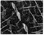
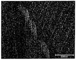
- An example of the STEM bright field image thus obtained is shown in FIG. Further, a mapping image of Cu element in the same visual field is shown in FIG. 2, and a mapping image of M element is shown in FIG.
- the crystal phases having the orientation in the same direction are the same crystal grains.
- a relatively white region is a region having a high Cu concentration
- a relatively white region is a region having a high M concentration.
- a region where both the Cu concentration and the M concentration are high when FIGS. 2 and 3 are overlapped corresponds to the Cu—M rich phase.
- a Cu-M rich phase is formed in a lump shape
- a Cu rich phase is also formed in a linear shape.
- a region adjacent to the Cu rich phase corresponds to the cell phase
- a region surrounded by the Cu rich phase corresponds to a cell structure region.
- a three-dimensional atom probe (3-Dimension Atom Probe: 3DAP) may be used for measuring the concentration of each phase element.
- the analysis method using 3DAP is an analysis method in which an observation sample is field-evaporated by applying a voltage, and an atomic arrangement is specified by detecting a field-evaporated ion with a two-dimensional detector. By identifying the ion species from the time of flight until reaching the two-dimensional detector, continuously detecting the individually detected ions in the depth direction, and arranging (reconstructing) the ions in the detected order A three-dimensional atomic distribution can be obtained. Compared with the TEM-EDX concentration measurement, the concentration of each element in each crystal phase can be measured more accurately.
- AP pick-up atom probe
- Measurement by 3DAP is performed on the inside of the sintered body.
- the measurement inside the sintered body is as follows. First, in the central part of the longest side in the surface having the maximum area, the composition is measured at the surface part and inside of the cross section cut perpendicularly to the side (in the case of a curve, perpendicular to the tangent to the central part). In the cross section, the measurement point is a corner of the first reference line drawn to the end perpendicular to the side and extending to the end, starting from a position 1/2 of each side, and the center of each corner.
- a second reference line drawn inward toward the end at a position that is 1/2 of the inner angle of the first angle, and the length of the reference line from the start point of the first reference line and the second reference line The 1% position is defined as the surface portion, and the 40% position is defined as the interior.
- angular part has a curvature by chamfering etc., let the intersection which extended the adjacent edge
- the reference line is a total of eight lines, each of the first reference line and the second reference line, and the measurement points are on the surface and inside. There are 8 places each. In the present embodiment, it is preferable that all of the eight portions in the surface portion and inside are within the above-described composition range, but it is sufficient that at least four portions in the surface portion and inside each are within the above-described composition range. In this case, the relationship between the surface portion and the inside at one reference line is not defined. Observation is performed after the observation surface inside the sintered body thus defined is polished and smoothed.
- the observation location of TEM-EDX in the concentration measurement is 20 arbitrary points in the main phase and Cu-M rich phase, and the average of the measured values obtained by removing the maximum value and the minimum value from the measured values at these points. A value is obtained, and this average value is taken as the concentration of each element.
- the measurement of 3DAP is based on this.
- the Cu concentration profile in the Cu rich phase is preferably sharper.
- the full width at half maximum (FWHM: Full Width at Half Maximum) of Cu is preferably 5 nm or less, and in such a case, a higher coercive force can be obtained. This is because when the distribution of Cu in the Cu-rich phase is sharp, a domain wall energy difference between the cell phase and the Cu-rich phase is abruptly generated, and the domain wall is more easily pinned.
- the full width at half maximum (FWHM) of the Cu concentration profile in the Cu-rich phase is determined as follows. Based on the above-described method, the highest Cu concentration (PCu) is obtained from the 3DAP Cu profile, and the peak width at which the value is half the value (PCu / 2), that is, the half width (FWHM) is obtained. . Such measurement is performed on 10 peaks, and the average value of these values is defined as the half width (FWHM) of the Cu profile.
- the full width at half maximum (FWHM) of the Cu profile is 3 nm or less, the effect of further increasing the coercive force is improved, and in the case of 2 nm or less, a more excellent coercive force improving effect can be obtained.
- the diameters of the cell phase, Cu-M rich phase, and Cu rich phase can be obtained as follows.
- an arbitrary phase is selected, and the longest straight line A having both ends contacting another phase is drawn for the selected phase.
- a straight line B that is perpendicular to the straight line A and whose both ends are in contact with another phase is drawn.
- the average of the lengths of the straight lines A and B is defined as a phase diameter D.
- D of one or more arbitrary phases is calculated
- the average grain size of the crystal grains constituting the main phase can be measured by an electron backscatter diffraction pattern method using SEM (SEM-Electron Backscattering Pattern: SEM-EBSP).
- SEM-EBSP SEM-Electron Backscattering Pattern
- the procedure for determining the average grain size of crystal grains is shown below.
- the sample is embedded in an epoxy resin, machine-polished and buffed, and then washed with water and sprayed with air blow.
- the surface of the sprinkled sample is treated with a dry etching apparatus.
- the surface of the sample is observed with a scanning electron microscope S-4300SE (manufactured by Hitachi High-Technologies Corp.) attached with EBSD system-Digiview (manufactured by TSL Corp.).
- the observation conditions are an acceleration voltage of 30 kV and a measurement area of 500 ⁇ m ⁇ 500 ⁇ m. From the observation results, the average grain size of the crystal grains existing within the measurement area is determined under the
- the grain area is an area in the same crystal grain surrounded by the grain boundary phase
- the average grain area is an average value of the area of the crystal grains existing in the measurement area range.
- the particle diameter is the diameter of a perfect circle having the same area as that in the same crystal grain
- the average particle diameter is the average value of the grain diameters of the crystal grains present in the measurement area range. Note that crystal grains having a grain size of 10 ⁇ m or less may be in a different phase, and therefore the average grain size is determined by ignoring crystal grains having a grain size of 10 ⁇ m or less.
- the squareness ratio is defined as follows. First, DC magnetization characteristics at room temperature are measured with a DC BH tracer. Next, determine the measurement result from the basic characteristics of the magnet from the BH curve obtained residual magnetization M r and coercivity i H C and the maximum energy product (BH) max. At this time, the theoretical maximum value by using the M r (BH) max is obtained by the following equation (1).
- (BH) max (theoretical value) M r 2 / 4 ⁇ 0 ⁇ (1)
- the squareness ratio is evaluated by the ratio of (BH) max and (BH) max (theoretical value) obtained by measurement, and is obtained by the following formula (2).
- the permanent magnet of this embodiment is also used as a bond magnet, for example.
- the magnet material of this embodiment for the variable magnet in the variable magnetic flux drive system as disclosed in Japanese Patent Application Laid-Open No. 2008-29148 or 2008-43172, the efficiency of the system is improved and the size is reduced. And cost reduction.
- ⁇ Permanent magnet manufacturing method> an example of a method for manufacturing a permanent magnet will be described. First, an alloy powder containing a predetermined element necessary for the synthesis of a permanent magnet is prepared. Next, an alloy powder is filled in a mold placed in an electromagnet, and a green compact having a crystal axis oriented is manufactured by pressure forming while applying a magnetic field.
- an alloy powder can be prepared by producing a flake-like alloy ribbon by a strip casting method and thereafter pulverizing the alloy ribbon.
- the molten alloy was poured into a cooling roll rotating at a peripheral speed of 0.1 m / second or more and 20 m / second or less to continuously solidify to a thickness of 1 mm or less.
- a ribbon can be produced.
- the peripheral speed is less than 0.1 m / second, composition variations tend to occur in the ribbon.
- the peripheral speed exceeds 20 m / sec, the magnetic properties may be deteriorated, for example, crystal grains are excessively refined.
- the peripheral speed of the cooling roll is 0.3 m / second or more and 15 m / second or less, more preferably 0.5 m / second or more and 12 m / second or less.
- an alloy powder can be prepared by pulverizing an alloy ingot obtained by casting after arc melting or high frequency melting. Further, the alloy powder may be prepared using a mechanical alloying method, a mechanical grinding method, a gas atomizing method, a reducing diffusion method, or the like.
- the material can be homogenized by subjecting the alloy powder or the material of the alloy before grinding to a heat treatment.
- the material can be pulverized using a jet mill, a ball mill, or the like.
- the powder can be prevented from being oxidized by grinding the material in an inert gas atmosphere or an organic solvent.
- the degree of orientation becomes high, and the coercive force is increased. growing.
- pulverization by a jet mill is preferable.
- the ratio of the powder having a particle size of 10 ⁇ m or more in the pulverized powder is 10% or less of the whole powder.
- the Fe concentration is 23 atomic% or more, the amount of heterogeneous phase in the ingot as a raw material increases. In this different phase, not only the amount of powder increases but also the particle size tends to increase, and the particle size may be 20 ⁇ m or more.
- a powder having a particle diameter of 15 ⁇ m or more may be directly converted into a different-phase powder.
- the pulverized powder containing such a heterogeneous coarse powder is pressed in a magnetic field to form a sintered body, the heterogeneous phase remains, causing a decrease in coercive force, a decrease in magnetization, a decrease in squareness, and the like.
- the squareness decreases, magnetization becomes difficult. In particular, it is difficult to magnetize the rotor after assembly.
- the coercive force can be increased while suppressing the decrease in the squareness ratio in a high Fe concentration composition containing 23 atomic% or more of Fe by making the powder having a particle diameter of 10 ⁇ m or more 10% or less of the whole. it can.
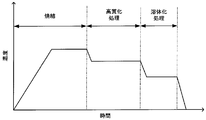
- FIG. 4 is a diagram for explaining an example of a method for manufacturing a permanent magnet according to the present embodiment, in which the horizontal axis represents time and the vertical axis represents temperature.
- a high quality treatment is performed in the manufacturing method of a permanent magnet.
- the high-quality treatment is a treatment for controlling a metal structure, particularly a macro structure.
- the solution treatment is a process for forming a TbCu 7- type crystal phase (1-7-type crystal phase) that becomes a precursor of a phase-separated structure.
- the green compact is heat-treated by holding it at a temperature of 1180 ° C. to 1220 ° C. for 1 hour to 15 hours.
- the holding temperature is less than 1180 ° C.
- the density of the produced sintered body tends to be low.
- the temperature is higher than 1220 ° C.
- the magnetic properties may deteriorate due to excessive evaporation of Sm in the powder.
- a more preferable holding temperature is 1190 ° C. or higher and 1210 ° C. or lower.
- the holding time is less than 1 hour, the density tends to be non-uniform, and the magnetization is likely to decrease.
- the crystal grain size of the sintered body is reduced, and the grain boundary phase ratio is increased. Is prone to decline.
- the heat treatment time exceeds 15 hours, evaporation of the R element in the powder becomes excessive, and the magnetic properties may be deteriorated.
- a more preferable holding time is 2 hours or more and 13 hours or less, and further preferably 3 hours or more and 10 hours or less. Note that oxidation can be suppressed by performing heat treatment in vacuum or argon gas.
- a sintered compact density can be improved by maintaining a vacuum until it becomes near holding temperature, switching to Ar atmosphere after that, and keeping isothermal.
- the heat treatment is performed by holding at a temperature lower by 10 ° C. or more than the heat treatment temperature during sintering and at a temperature higher by 10 ° C. or more than the heat treatment temperature during solution treatment for 2 hours or more and 12 hours or less.
- the temperature is low, and it is difficult to sufficiently remove the heterogeneous phase generated during sintering from the viewpoint of element diffusion rate. Further, the grain growth rate is slow, and there is a possibility that a sufficient crystal grain size cannot be obtained, and improvement in the squareness ratio cannot be expected.
- the heterogeneous phase can be sufficiently removed and the crystal grains constituting the main phase can be enlarged.
- the holding temperature during the high-quality treatment is preferably, for example, 1140 ° C. or higher and 1190 ° C. or lower.
- the squareness ratio may decrease.
- the heat treatment time in the high-quality treatment is more preferably 4 hours or longer and 10 hours or shorter, and further preferably 6 hours or longer and 8 hours or shorter. In order to prevent oxidation, it is preferable to perform the high-quality treatment in a vacuum or an inert atmosphere such as argon gas.
- heat treatment is performed by holding at a temperature of 1090 ° C. or higher and 1130 ° C. or lower for 3 hours or longer and 28 hours or shorter.
- the holding temperature is preferably 1100 ° C. or higher and 1130 ° C. or lower.
- the constituent phases tend to be non-uniform, the coercive force tends to decrease, the crystal grain size of the metal structure tends to be small, and the grain boundary phase ratio is high.
- the holding time is preferably 4 hours or longer and 24 hours or shorter, and more preferably 10 hours or longer and 18 hours or shorter. Note that oxidation of the powder can be suppressed by performing a solution treatment in a vacuum or an inert atmosphere such as argon gas.
- rapid cooling is performed after isothermal holding.
- the TbCu 7- type crystal phase can be stabilized and coercive force is easily developed.
- the cooling rate is less than 170 ° C./min, a Ce 2 Ni 7 type crystal phase (2-7 type crystal phase) is likely to be generated during cooling. Due to the presence of the 2-7 type crystal phase, the magnetization may decrease, and the coercive force may also decrease. This is because in the 2-7 type crystal phase, Cu is often concentrated, which decreases the Cu concentration in the main phase and makes phase separation difficult due to aging treatment.
- the cooling rate tends to be important in a composition containing an Fe concentration of 23 atomic% or more.
- the cooling at the time of performing the solution treatment after the high-quality treatment is more gradual than the rapid cooling after the solution treatment, that is, slow cooling.
- slow cooling it is preferable to perform slow cooling at a cooling rate of 15 ° C./min or less, preferably 10 ° C./min or less after the high-quality treatment.
- the aging treatment is a treatment for increasing the coercive force of the magnet by controlling the metal structure, and aims to phase-separate the metal structure of the magnet into a plurality of phases.
- the temperature is raised to a temperature of 760 ° C. or higher and 850 ° C. or lower, and then held at that temperature for 20 hours or longer and 60 hours or shorter (first holding).
- first holding After slow cooling to a temperature of 350 ° C. or more and 650 ° C. or less at a cooling rate of 0.2 ° C./min or more and 0.8 ° C./min or less, the temperature is maintained for 0.5 hours or more and 8 hours or less.
- Heat treatment is performed by (second holding). Then, it cools to room temperature.
- a sintered magnet can be obtained as described above.
- the holding temperature in the first holding is more preferably 780 ° C. or higher and 840 ° C. or lower, for example.
- the holding time in the first holding is more preferably 25 hours or more and 40 hours or less, for example.
- the cell wall phase becomes excessively thick and the magnetization tends to decrease. Moreover, when exceeding 0.8 degree-C / min, the difference of Cu concentration of a cell phase and a cell wall phase is not fully obtained, and a coercive force tends to fall. Moreover, when it cools slowly to less than 350 degreeC, the low temperature heterogeneous phase as mentioned above is easy to be generated. Moreover, when it cools to the temperature exceeding 430 degreeC, Cu density
- the aging treatment it may be held at a predetermined temperature for a certain period of time during slow cooling, and further slow cooling from there. Further, the above aging treatment is set as the main aging treatment, and the preliminary aging treatment is performed by holding the aging treatment at a temperature lower than the holding temperature in the first holding before the main aging treatment and in a time shorter than the holding time in the first holding. May be performed. The squareness ratio can be further increased by the holding during the slow cooling and the pre-aging treatment.
- a high quality treatment is performed.
- heat treatment is performed in a specific temperature range that is lower than the holding temperature during sintering and higher than the holding temperature during solution treatment.
- the heterogeneous phase can be sufficiently removed, expansion of the diameter of the Cu-M rich phase is suppressed.
- the diameter of the Cu-M rich phase can be reduced, and the influence on the surrounding composition of the Cu-M rich phase can be suppressed.
- the crystal grains constituting the main phase can be increased, the volume fraction of the grain boundary phase can be relatively reduced. Therefore, in the metal structure, a cell structure is easily formed even around the grain boundary phase. For example, a good squareness ratio can be obtained even in a permanent magnet containing 25 atomic% or more of Fe.
- the high-quality treatment may be performed after sintering and before the aging treatment, and is not limited to the order of the manufacturing steps shown in FIG.
- the high-quality treatment is divided into a first solution treatment and a second solution treatment (also referred to as a re-solution treatment), and the high-quality treatment is performed after the first solution treatment.
- a second solution treatment may be performed later.
- the permanent magnet of the first embodiment can be used for various motors and generators. Further, it can be used as a fixed magnet or a variable magnet of a variable magnetic flux motor or a variable magnetic flux generator. Various motors and generators are configured by using the permanent magnet of the first embodiment.
- the permanent magnet of the first embodiment is applied to a variable magnetic flux motor, the technology disclosed in Japanese Patent Application Laid-Open Nos. 2008-29148 and 2008-43172 is used for the configuration and drive system of the variable magnetic flux motor. Can be applied.
- FIG. 5 is a diagram showing a permanent magnet motor in the present embodiment.
- a rotor (rotor) 3 is disposed in a stator (stator) 2.
- the permanent magnet 5 which is the permanent magnet of the first embodiment is arranged.
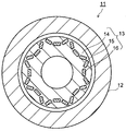
- FIG. 6 is a view showing a variable magnetic flux motor according to the present embodiment.
- a rotor (rotor) 13 is disposed in a stator (stator) 12.
- the permanent magnets of the first embodiment are arranged as a fixed magnet 15 and a variable magnet 16.
- the magnetic flux density (magnetic flux amount) of the variable magnet 16 can be varied. Since the magnetization direction of the variable magnet 16 is orthogonal to the Q-axis direction, it is not affected by the Q-axis current and can be magnetized by the D-axis current.
- the rotor 13 is provided with a magnetized winding (not shown). By passing a current from the magnetization circuit through the magnetization winding, the magnetic field directly acts on the variable magnet 16.
- a coercive force suitable for the fixed magnet 15 can be obtained.
- the coercive force is 100 kA / m or more and 500 kA / m or less by changing various conditions (such as aging treatment conditions) of the manufacturing method described above. Should be controlled within the range.
- the permanent magnet of the first embodiment can be used for both the fixed magnet 15 and the variable magnet 16, but the first embodiment is used for either one of the magnets. Permanent magnets may be used. Since the variable magnetic flux motor 11 can output a large torque with a small device size, the variable magnetic flux motor 11 is suitable for a motor such as a hybrid vehicle or an electric vehicle that requires high output and miniaturization of the motor.
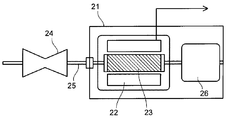
- FIG. 7 shows the generator according to the present embodiment.
- a generator 21 shown in FIG. 7 includes a stator (stator) 22 using the permanent magnet of the present embodiment.
- a rotor (rotor) 23 disposed inside the stator (stator) 22 is connected to a turbine 24 provided at one end of the generator 21 via a shaft 25.
- the turbine 24 is rotated by fluid supplied from the outside, for example.
- the shaft 25 can be rotated by transmitting dynamic rotation such as regenerative energy of an automobile instead of the turbine 24 rotated by a fluid.
- Various known configurations can be employed for the stator 22 and the rotor 23.
- the shaft 25 is in contact with a commutator (not shown) disposed on the side opposite to the turbine 24 with respect to the rotor 23, and an electromotive force generated by the rotation of the rotor 23 is used as an output of the generator 21 as a phase separation bus.
- the power is boosted to the system voltage and transmitted through a main transformer (not shown).
- the generator 21 may be either a normal generator or a variable magnetic flux generator. Note that the rotor 23 is charged by static electricity from the turbine 2 or a shaft current accompanying power generation. Therefore, the generator 21 is provided with a brush 26 for discharging the charge of the rotor 23.
- Example 1 Each raw material used for the permanent magnet was weighed and mixed at a predetermined ratio, and then melted in an Ar gas atmosphere to produce an alloy ingot.
- the alloy ingot was held at 1170 ° C. for 16 hours for heat treatment, and then the alloy ingot was coarsely pulverized and pulverized by a jet mill to prepare an alloy powder as a magnet raw material powder.
- the obtained alloy powder was press-molded in a magnetic field to produce a compression molded body.
- the compression molded body of the alloy powder is placed in a sintering furnace chamber, and after the inside of the chamber is evacuated, the temperature is raised to 1175 ° C. and held at the ultimate temperature for 20 minutes, after which Ar gas is introduced, and Ar The temperature was raised to 1220 ° C. in the atmosphere, and the sintering was performed by maintaining the temperature for 4 hours.
- the high-quality treatment was performed by holding at 1190 ° C. for 6 hours.
- the cooling rate after the solution treatment was 170 ° C./min.
- the sintered body after the solution treatment was heated to 750 ° C., held at the ultimate temperature for 2 hours, and then gradually cooled to 350 ° C. at a cooling rate of 1.5 ° C./min.
- the temperature was raised to 835 ° C. and held at the ultimate temperature for 30 hours. Thereafter, it was gradually cooled to 550 ° C. at a cooling rate of 1.0 ° C./min, and held at the ultimate temperature for 4 hours. Thereafter, it was gradually cooled to 400 ° C. at a cooling rate of 1.0 ° C./min, and held at the ultimate temperature for 1 hour.
- the magnet was obtained by furnace-cooling to room temperature.
- composition analysis of the magnet was performed by the inductively coupled plasma (ICP) method.
- ICP method was performed according to the following procedure. First, a sample collected from the described measurement location was pulverized with a mortar, and a certain amount of the pulverized sample was weighed and placed in a quartz beaker. Further, mixed acid (acid containing nitric acid and hydrochloric acid) was put into the beaker and heated to about 140 ° C. on a hot plate to completely dissolve the sample in the beaker. After further cooling, it was transferred to a PFA volumetric flask and the volume was adjusted to obtain a sample solution.
- the components contained in the sample solution were quantified by a calibration curve method using an ICP emission spectroscopic analyzer.
- ICP emission spectroscopic analyzer SPS4000 manufactured by SII Nano Technology was used.
- the composition of the obtained magnet is as shown in Table 1. Further, the Cu concentration and M concentration of the Cu—M rich phase, the diameter of the Cu—M rich phase, the average grain size, the squareness ratio, the coercive force, and the remanent magnetization were measured. The results are shown in Table 3.
- HD2300 manufactured by Hitachi High-Tech was used as a measuring device.
- Example 3 Example 4, Example 5
- Each raw material was weighed and mixed at a predetermined ratio, and then melted at a high frequency in an Ar gas atmosphere to prepare an alloy ingot.
- heat treatment was performed at 1180 ° C. for 8 hours, followed by rapid cooling to cool to room temperature.
- coarse pulverization and pulverization with a jet mill were carried out to prepare an alloy powder as a raw material powder for the magnet. Further, the alloy powder was press-molded in a magnetic field to produce a compression molded body.
- the compression molded body of the alloy powder is placed in a chamber of a sintering furnace, the inside of the chamber is evacuated to a vacuum degree of 8.5 ⁇ 10 ⁇ 3 Pa, and then the temperature is raised to 1170 ° C.
- Ar gas was introduced into the chamber.
- the temperature in the chamber in the Ar atmosphere was raised to 1190 ° C. and held at the ultimate temperature for 5 hours for sintering.
- the high-quality treatment was performed by holding at 1160 ° C. for 2 hours.
- gradual cooling was performed to 1140 ° C. at a cooling rate of 4.0 ° C./min, and the sintered body was held at the ultimate temperature for 16 hours for solution treatment, and then cooled to room temperature.
- the cooling rate after the solution treatment was 150 ° C./min.
- the sintered body after the solution treatment was heated to 700 ° C. and held at the ultimate temperature for 2 hours, and subsequently heated to 815 ° C. as an aging treatment and held at the ultimate temperature for 50 hours. Thereafter, it was gradually cooled to 450 ° C. at a cooling rate of 0.6 ° C./min, and held at the ultimate temperature for 4 hours. Then, it was gradually cooled to 380 ° C. at a cooling rate of 0.5 ° C./min, and held at the ultimate temperature for 1 hour. Then, the magnet was obtained by furnace-cooling to room temperature.
- the components contained in the sample solution were quantified by a calibration curve method using the ICP emission spectroscopic analyzer.
- the composition of the obtained magnet is as shown in Table 1.
- the Cu concentration and M concentration of the Cu—M rich phase, the diameter of the Cu—M rich phase, the average grain size, the squareness ratio, the coercive force, and the residual magnetization were measured. The results are shown in Table 3.
- Example 6 Each raw material was weighed and mixed at a predetermined ratio, and then melted at a high frequency in an Ar gas atmosphere to prepare an alloy ingot. After subjecting the alloy ingot to coarse pulverization, heat treatment was performed at 1180 ° C. for 8 hours, followed by rapid cooling to cool to room temperature. Further, coarse pulverization and pulverization with a jet mill were carried out to prepare an alloy powder as a raw material powder for the magnet. Further, the alloy powder was press-molded in a magnetic field to produce a compression molded body.
- the compression molded body of the alloy powder is placed in a chamber of a sintering furnace, the inside of the chamber is evacuated to a vacuum degree of 7.5 ⁇ 10 ⁇ 3 Pa, and then the temperature is raised to 1160 ° C. After holding for a minute, Ar gas was introduced into the chamber. Sintering was performed by raising the temperature in the chamber in an Ar atmosphere to 1180 ° C. and holding at the ultimate temperature for 5 hours. Next, as shown in Table 2, the high-quality treatment was performed by holding at 1150 ° C. for 10 hours. Next, gradual cooling was performed to 1120 ° C. at a cooling rate of 4.0 ° C./min, and the sintered body was held at the ultimate temperature for 12 hours for solution treatment, and then cooled to room temperature. The cooling rate after the solution treatment was 220 ° C./min.
- the sintered body after the solution treatment was heated to 670 ° C. and held at the ultimate temperature for 1 hour, and subsequently, as an aging treatment, the temperature was raised to 840 ° C. and held at the ultimate temperature for 45 hours. Thereafter, it was gradually cooled to 500 ° C. at a cooling rate of 0.6 ° C./min, and held at the ultimate temperature for 1 hour. Thereafter, it was gradually cooled to 400 ° C. at a cooling rate of 0.5 ° C./min, and held at the ultimate temperature for 1 hour. Then, the magnet was obtained by furnace-cooling to room temperature.
- the composition of each magnet was confirmed by the ICP method.
- the composition of the obtained magnet is as shown in Table 1.
- the Cu concentration and M concentration of the Cu—M rich phase, the diameter of the Cu—M rich phase, the average grain size, the squareness ratio, the coercive force, and the residual magnetization were measured. The results are shown in Table 3.
- Example 8 Each raw material was weighed and mixed at a predetermined ratio, and then melted at a high frequency in an Ar gas atmosphere to prepare an alloy ingot.
- the alloy ingot was coarsely pulverized, then subjected to a heat treatment at 1165 ° C. for 12 hours, and cooled rapidly to room temperature. Further, an alloy powder was prepared as a raw material powder for the magnet by coarse pulverization and pulverization by a jet mill. Further, the alloy powder was press-molded in a magnetic field to produce a compression molded body.
- the compression molded body of the alloy powder is placed in a chamber of a sintering furnace, the inside of the chamber is evacuated to a vacuum degree of 9.0 ⁇ 10 ⁇ 3 Pa, and then the temperature is raised to 1160 ° C. After holding for a minute, Ar gas was introduced into the chamber. The temperature in the chamber in the Ar atmosphere was raised to 1190 ° C. and held at the ultimate temperature for 4 hours for sintering.
- the high-quality treatment was performed by holding at 1160 ° C. for 6 hours. Next, it was gradually cooled to 1120 ° C. at a cooling rate of 5.0 ° C./min, and the sintered body was held at the ultimate temperature for 12 hours for solution treatment, and then cooled to room temperature. The cooling rate after the solution treatment was 170 ° C./min.
- the sintered body after the solution treatment was heated to 710 ° C., held at the ultimate temperature for 4 hours, and subsequently heated to 830 ° C. as an aging treatment and held at the ultimate temperature for 45 hours. Thereafter, it was gradually cooled to 600 ° C. at a cooling rate of 0.8 ° C./min, and held at the ultimate temperature for 4 hours. Thereafter, it was gradually cooled to 400 ° C. at a cooling rate of 0.5 ° C./min and held at the ultimate temperature for 1 hour. Then, the magnet was obtained by furnace-cooling to room temperature.
- the composition of each magnet was confirmed by the ICP method.
- the composition of the obtained magnet is as shown in Table 1.
- the Cu concentration and M concentration of the Cu—M rich phase, the diameter of the Cu—M rich phase, the average grain size, the squareness ratio, the coercive force, and the residual magnetization were measured. The results are shown in Table 3.
- Example 9 to 13 An alloy powder having the same composition as in Example 8 was used as a raw material, and press-molded in a magnetic field to produce a compression molded body. Next, the compression molded body of the alloy powder is placed in a chamber of a sintering furnace, the inside of the chamber is evacuated to a vacuum degree of 9.0 ⁇ 10 ⁇ 3 Pa, and then the temperature is raised to 1160 ° C. After holding for a minute, Ar gas was introduced into the chamber. The temperature in the chamber in the Ar atmosphere was raised to 1190 ° C. and held at the ultimate temperature for 4 hours for sintering.
- Example 9 a high-quality treatment and a solution treatment were performed. As shown in Table 2, in Example 9, the high-quality treatment was performed by holding at 1180 ° C. for 6 hours. Next, it was gradually cooled to 1120 ° C. at a cooling rate of 5.0 ° C./min, and the sintered body was held at the ultimate temperature for 12 hours for solution treatment, and then cooled to room temperature. The cooling rate after the solution treatment was 170 ° C./min.
- Example 10 the high-quality treatment was performed by holding at 1130 ° C. for 6 hours. Next, it was gradually cooled to 1120 ° C. at a cooling rate of 5.0 ° C./min, and the sintered body was held at the ultimate temperature for 12 hours for solution treatment, and then cooled to room temperature. The cooling rate after the solution treatment was 170 ° C./min.
- Example 11 the high-quality treatment was performed by holding at 1160 ° C. for 10 hours. Next, it was gradually cooled to 1120 ° C. at a cooling rate of 5.0 ° C./min, and the sintered body was held at the ultimate temperature for 12 hours for solution treatment, and then cooled to room temperature. The cooling rate after the solution treatment was 170 ° C./min.
- Example 12 the high-quality treatment was performed by holding at 1160 ° C. for 2 hours. Next, it was gradually cooled to 1120 ° C. at a cooling rate of 5.0 ° C./min, and the sintered body was held at the ultimate temperature for 12 hours for solution treatment, and then cooled to room temperature. The cooling rate after the solution treatment was 170 ° C./min.
- Example 13 the high-quality treatment was performed by holding at 1160 ° C. for 6 hours. Next, gradual cooling was performed to 1120 ° C. at a cooling rate of 2.0 ° C./min, the sintered body was held at the ultimate temperature for 12 hours to perform solution treatment, and then cooled to room temperature. The cooling rate after the solution treatment was 170 ° C./min.
- Example 8 Thereafter, in the same manner as in Example 8, a magnet was obtained by performing an aging treatment on the sintered body after the solution treatment in each Example.
- the composition of each magnet was confirmed by the ICP method.
- the composition of the obtained magnet is as shown in Table 1.
- the Cu concentration and M concentration of the Cu—M rich phase, the diameter of the Cu—M rich phase, the average grain size, the squareness ratio, the coercive force, and the residual magnetization were measured. The results are shown in Table 3.
- Example 14 An alloy powder having the same composition as in Example 3 was used as a raw material, and press-molded in a magnetic field in the same manner as in Example 3 to produce a compression molded body.
- the compression molded body of the alloy powder is placed in a chamber of a sintering furnace, the inside of the chamber is evacuated to a vacuum degree of 9.0 ⁇ 10 ⁇ 3 Pa, and then the temperature is raised to 1160 ° C.
- Ar gas was introduced into the chamber. The temperature in the chamber in the Ar atmosphere was raised to 1190 ° C. and held at the ultimate temperature for 4 hours for sintering.
- Example 14 high quality treatment was performed. As shown in Table 2, in Example 14, the high-quality treatment was performed by holding at 1160 ° C. for 8 hours. Thereafter, magnets were obtained by performing each step such as solution treatment and aging treatment by the same method and conditions as in Example 3.
- the composition of each magnet was confirmed by the ICP method.
- the composition of the obtained magnet is as shown in Table 1.
- the Cu concentration and M concentration of the Cu—M rich phase, the diameter of the Cu—M rich phase, the average grain size, the squareness ratio, the coercive force, and the residual magnetization were measured. The results are shown in Table 3.
- Example 15 An alloy powder having the same composition as in Example 4 was used as a raw material, and press-molded in a magnetic field in the same manner as in Example 4 to produce a compression molded body.
- the compression molded body of the alloy powder is placed in a chamber of a sintering furnace, the inside of the chamber is evacuated to a vacuum degree of 9.0 ⁇ 10 ⁇ 3 Pa, and then the temperature is raised to 1160 ° C.
- Ar gas was introduced into the chamber. The temperature in the chamber in the Ar atmosphere was raised to 1190 ° C. and held at the ultimate temperature for 4 hours for sintering.
- Example 15 high quality treatment was performed. As shown in Table 2, in Example 15, the high-quality treatment was performed by holding at 1160 ° C. for 8 hours. Thereafter, a magnet was obtained by performing each step such as solution treatment and aging treatment by the same method and conditions as in Example 4.
- the composition of each magnet was confirmed by the ICP method.
- the composition of the obtained magnet is as shown in Table 1.
- the Cu concentration and M concentration of the Cu—M rich phase, the diameter of the Cu—M rich phase, the average grain size, the squareness ratio, the coercive force, and the residual magnetization were measured. The results are shown in Table 3.
- the high-quality treatment was performed by holding at 1185 ° C. for 6 hours. Next, it was gradually cooled to 1120 ° C. at a cooling rate of 5.0 ° C./min, and the sintered body was held at the ultimate temperature for 12 hours for solution treatment, and then cooled to room temperature.
- the cooling rate after the solution treatment was 170 ° C./min.
- the high-quality treatment was performed by holding at 1125 ° C. for 6 hours. Next, it was gradually cooled to 1120 ° C. at a cooling rate of 5.0 ° C./min, and the sintered body was held at the ultimate temperature for 12 hours for solution treatment, and then cooled to room temperature.
- the cooling rate after the solution treatment was 170 ° C./min.
- the high-quality treatment was performed by holding at 1160 ° C. for 0.5 hours. Next, it was gradually cooled to 1120 ° C. at a cooling rate of 5.0 ° C./min, and the sintered body was held at the ultimate temperature for 12 hours for solution treatment, and then cooled to room temperature. The cooling rate after the solution treatment was 170 ° C./min.
- the high-quality treatment was performed by holding at 1160 ° C. for 20 hours. Next, it was gradually cooled to 1120 ° C. at a cooling rate of 5.0 ° C./min, and the sintered body was held at the ultimate temperature for 12 hours for solution treatment, and then cooled to room temperature.
- the cooling rate after the solution treatment was 170 ° C./min.
- Example 8 Thereafter, in the same manner as in Example 8, a magnet was obtained by performing an aging treatment on the sintered body after solution treatment in each comparative example.
- the composition of the magnet was confirmed by the ICP method.
- the composition of each magnet is as shown in Table 1.
- the Cu concentration and M concentration of the Cu—M rich phase, the diameter of the Cu—M rich phase, the average grain size, the squareness ratio, the coercive force, and the residual magnetization were measured. The results are shown in Table 3.
- the diameter of the Cu-M rich phase is smaller than that of the permanent magnet of Comparative Example 3 in which the high-quality treatment is not performed, and the average of the crystal grains constituting the main phase Since the particle size is large, a favorable squareness ratio, high coercive force, and high magnetization are exhibited. From this, it can be seen that the magnet characteristics can be improved by performing the high-quality treatment.
- the diameter of the Cu-M rich phase is smaller than that of the permanent magnet of Comparative Example 4 in which the holding temperature in the high-quality treatment is 1185 ° C., and the main phase is configured. Since the average grain size of the crystal grains is large, a favorable squareness ratio, high coercive force, and high magnetization are exhibited. From this, it can be seen that the magnet characteristics can be improved by controlling the holding temperature during slow cooling in the high-quality treatment.
- the diameter of the Cu-M rich phase is smaller than that of the permanent magnet of Comparative Example 6 in which the retention time in the high-quality treatment is 0.5 hour. Since the average grain size of the crystal grains constituting the material is large, a favorable squareness ratio, high coercive force, and high magnetization are exhibited.
- the retention time in the high-quality treatment is made longer than those of Examples 3 to 5 having the same composition, so that a better squareness ratio and higher coercive force are achieved. , And express high magnetization. From this, it can be seen that the magnet characteristics can be improved by controlling the holding time during slow cooling in the high-quality treatment.
- the Fe concentration was 23% or more by controlling the size of the Cu-M rich phase and the grain size of the crystal grains constituting the main phase. Even if it is a case, all are exhibiting favorable squareness ratio, high coercive force, and high magnetization. From this, it can be seen that the permanent magnets of Examples 1 to 16 have excellent magnet characteristics.
Abstract
Description
本実施形態の永久磁石について以下に説明する。 (First embodiment)
The permanent magnet of this embodiment will be described below.
本実施形態の永久磁石は、組成式:RpFeqMrCutCo100-p-q-r-t
(式中、Rは希土類元素から選ばれる少なくとも1種の元素、MはZr、Ti、およびHfからなる群より選ばれる少なくとも1種の元素、pは10.8≦p≦12.5原子%を満足する数、qは25≦q≦40原子%を満足する数、rは0.88≦r≦4.5原子%を満足する数、tは3.5≦t≦13.5原子%を満足する数である)で表される組成を具備する。 <Configuration example of permanent magnet>
Permanent magnet of this embodiment, the composition formula: R p Fe q M r Cu t Co 100-p-q-r-t
(Wherein R is at least one element selected from rare earth elements, M is at least one element selected from the group consisting of Zr, Ti, and Hf, and p is 10.8 ≦ p ≦ 12.5 atomic%. Q is a number satisfying 25 ≦ q ≦ 40 atomic%, r is a number satisfying 0.88 ≦ r ≦ 4.5 atomic%, and t is 3.5 ≦ t ≦ 13.5 atomic% Is a number satisfying the above).
(BH)max(理論値)=Mr 2/4μ0・・・(1)
角型比は、測定で得られる(BH)maxと(BH)max(理論値)の比により評価され、下記式(2)により求められる。
(BH)max(実測値)/(BH)max(理論値)×100・・・(2) The squareness ratio is defined as follows. First, DC magnetization characteristics at room temperature are measured with a DC BH tracer. Next, determine the measurement result from the basic characteristics of the magnet from the BH curve obtained residual magnetization M r and coercivity i H C and the maximum energy product (BH) max. At this time, the theoretical maximum value by using the M r (BH) max is obtained by the following equation (1).
(BH) max (theoretical value) = M r 2 / 4μ 0 ··· (1)
The squareness ratio is evaluated by the ratio of (BH) max and (BH) max (theoretical value) obtained by measurement, and is obtained by the following formula (2).
(BH) max (actual value) / (BH) max (theoretical value) × 100 (2)
次に、永久磁石の製造方法例について説明する。まず、永久磁石の合成に必要な所定の元素を含む合金粉末を調製する。次に、電磁石の中に設置した金型内に合金粉末を充填し、磁場を印加しながら加圧成形することにより結晶軸を配向させた圧粉体を製造する。 <Permanent magnet manufacturing method>
Next, an example of a method for manufacturing a permanent magnet will be described. First, an alloy powder containing a predetermined element necessary for the synthesis of a permanent magnet is prepared. Next, an alloy powder is filled in a mold placed in an electromagnet, and a green compact having a crystal axis oriented is manufactured by pressure forming while applying a magnetic field.
第1の実施形態の永久磁石は、各種モータや発電機に使用することができる。また、可変磁束モータや可変磁束発電機の固定磁石や可変磁石として使用することも可能である。第1の実施形態の永久磁石を用いることによって、各種のモータや発電機が構成される。第1の実施形態の永久磁石を可変磁束モータに適用する場合、可変磁束モータの構成やドライブシステムには、特開2008-29148号公報や特開2008-43172号公報に開示されている技術を適用することができる。 (Second Embodiment)
The permanent magnet of the first embodiment can be used for various motors and generators. Further, it can be used as a fixed magnet or a variable magnet of a variable magnetic flux motor or a variable magnetic flux generator. Various motors and generators are configured by using the permanent magnet of the first embodiment. When the permanent magnet of the first embodiment is applied to a variable magnetic flux motor, the technology disclosed in Japanese Patent Application Laid-Open Nos. 2008-29148 and 2008-43172 is used for the configuration and drive system of the variable magnetic flux motor. Can be applied.
永久磁石に用いられる各原料を所定の比率で秤量して混合した後、Arガス雰囲気でアーク溶解して合金インゴットを作製した。上記合金インゴットを1170℃で16時間保持して熱処理を行った後、合金インゴットに対して粗粉砕とジェットミルによる粉砕とを実施し、磁石の原料粉末としての合金粉末を調製した。得られた合金粉末を磁界中でプレス成形して圧縮成形体を作製した。 (Example 1, Example 2)
Each raw material used for the permanent magnet was weighed and mixed at a predetermined ratio, and then melted in an Ar gas atmosphere to produce an alloy ingot. The alloy ingot was held at 1170 ° C. for 16 hours for heat treatment, and then the alloy ingot was coarsely pulverized and pulverized by a jet mill to prepare an alloy powder as a magnet raw material powder. The obtained alloy powder was press-molded in a magnetic field to produce a compression molded body.
各原料を所定の比率で秤量して混合した後、Arガス雰囲気中で高周波溶解して合金インゴットを作製した。合金インゴットに対し粗粉砕を実施した後に1180℃、8時間の熱処理を施し、急冷することにより室温まで冷却した。さらに粗粉砕とジェットミルによる粉砕とを実施し、磁石の原料粉末としての合金粉末を調製した。さらに上記合金粉末を磁界中でプレス成形して圧縮成形体を作製した。 (Example 3, Example 4, Example 5)
Each raw material was weighed and mixed at a predetermined ratio, and then melted at a high frequency in an Ar gas atmosphere to prepare an alloy ingot. After subjecting the alloy ingot to coarse pulverization, heat treatment was performed at 1180 ° C. for 8 hours, followed by rapid cooling to cool to room temperature. Further, coarse pulverization and pulverization with a jet mill were carried out to prepare an alloy powder as a raw material powder for the magnet. Further, the alloy powder was press-molded in a magnetic field to produce a compression molded body.
各原料を所定の比率で秤量して混合した後、Arガス雰囲気中で高周波溶解して合金インゴットを作製した。合金インゴットに対し粗粉砕を実施した後に1180℃、8時間の熱処理を施し、急冷することにより室温まで冷却した。さらに粗粉砕とジェットミルによる粉砕とを実施し、磁石の原料粉末としての合金粉末を調製した。さらに上記合金粉末を磁界中でプレス成形して圧縮成形体を作製した。 (Example 6, Example 7)
Each raw material was weighed and mixed at a predetermined ratio, and then melted at a high frequency in an Ar gas atmosphere to prepare an alloy ingot. After subjecting the alloy ingot to coarse pulverization, heat treatment was performed at 1180 ° C. for 8 hours, followed by rapid cooling to cool to room temperature. Further, coarse pulverization and pulverization with a jet mill were carried out to prepare an alloy powder as a raw material powder for the magnet. Further, the alloy powder was press-molded in a magnetic field to produce a compression molded body.
各原料を所定の比率で秤量して混合した後、Arガス雰囲気中で高周波溶解して合金インゴットを作製した。上記合金インゴットに対し粗粉砕を実施した後に1165℃、12時間の熱処理を施し、急冷することにより室温まで冷却した。さらに、粗粉砕とジェットミルによる粉砕とを磁石の原料粉末としての合金粉末を調製した。さらに上記合金粉末を磁界中でプレス成形して圧縮成形体を作製した。 (Example 8)
Each raw material was weighed and mixed at a predetermined ratio, and then melted at a high frequency in an Ar gas atmosphere to prepare an alloy ingot. The alloy ingot was coarsely pulverized, then subjected to a heat treatment at 1165 ° C. for 12 hours, and cooled rapidly to room temperature. Further, an alloy powder was prepared as a raw material powder for the magnet by coarse pulverization and pulverization by a jet mill. Further, the alloy powder was press-molded in a magnetic field to produce a compression molded body.
実施例8と同組成の合金粉末を原料に用い、磁界中でプレス成形して圧縮成形体を作製した。次に、合金粉末の圧縮成形体を焼結炉のチャンバ内に配置し、チャンバ内を真空度9.0×10⁻³Paの真空状態にした後に1160℃まで昇温させ、到達温度で30分間保持した後、チャンバ内にArガスを導入した。Ar雰囲気中としたチャンバ内の温度を1190℃まで昇温し、到達温度で4時間保持して焼結を行った。 (Examples 9 to 13)
An alloy powder having the same composition as in Example 8 was used as a raw material, and press-molded in a magnetic field to produce a compression molded body. Next, the compression molded body of the alloy powder is placed in a chamber of a sintering furnace, the inside of the chamber is evacuated to a vacuum degree of 9.0 × 10 −3 Pa, and then the temperature is raised to 1160 ° C. After holding for a minute, Ar gas was introduced into the chamber. The temperature in the chamber in the Ar atmosphere was raised to 1190 ° C. and held at the ultimate temperature for 4 hours for sintering.
実施例3と同組成の合金粉末を原料に用い、実施例3と同様に磁界中でプレス成形して圧縮成形体を作製した。次に、合金粉末の圧縮成形体を焼結炉のチャンバ内に配置し、チャンバ内を真空度9.0×10⁻³Paの真空状態にした後に1160℃まで昇温させ、到達温度で30分間保持した後、チャンバ内にArガスを導入した。Ar雰囲気中としたチャンバ内の温度を1190℃まで昇温し、到達温度で4時間保持して焼結を行った。 (Example 14)
An alloy powder having the same composition as in Example 3 was used as a raw material, and press-molded in a magnetic field in the same manner as in Example 3 to produce a compression molded body. Next, the compression molded body of the alloy powder is placed in a chamber of a sintering furnace, the inside of the chamber is evacuated to a vacuum degree of 9.0 × 10 −3 Pa, and then the temperature is raised to 1160 ° C. After holding for a minute, Ar gas was introduced into the chamber. The temperature in the chamber in the Ar atmosphere was raised to 1190 ° C. and held at the ultimate temperature for 4 hours for sintering.
実施例4と同組成の合金粉末を原料に用い、実施例4と同様に磁界中でプレス成形して圧縮成形体を作製した。次に、合金粉末の圧縮成形体を焼結炉のチャンバ内に配置し、チャンバ内を真空度9.0×10⁻³Paの真空状態にした後に1160℃まで昇温させ、到達温度で30分間保持した後、チャンバ内にArガスを導入した。Ar雰囲気中としたチャンバ内の温度を1190℃まで昇温し、到達温度で4時間保持して焼結を行った。 (Example 15)
An alloy powder having the same composition as in Example 4 was used as a raw material, and press-molded in a magnetic field in the same manner as in Example 4 to produce a compression molded body. Next, the compression molded body of the alloy powder is placed in a chamber of a sintering furnace, the inside of the chamber is evacuated to a vacuum degree of 9.0 × 10 −3 Pa, and then the temperature is raised to 1160 ° C. After holding for a minute, Ar gas was introduced into the chamber. The temperature in the chamber in the Ar atmosphere was raised to 1190 ° C. and held at the ultimate temperature for 4 hours for sintering.
実施例5と同組成の合金粉末を原料に用い、実施例5と同様に磁界中でプレス成形して圧縮成形体を作製した。次に、合金粉末の圧縮成形体を焼結炉のチャンバ内に配置し、チャンバ内を真空度9.0×10⁻³Paの真空状態にした後に1160℃まで昇温させ、到達温度で30分間保持した後、チャンバ内にArガスを導入した。Ar雰囲気中としたチャンバ内の温度を1190℃まで昇温し、到達温度で4時間保持して焼結を行った。 (Example 16)
An alloy powder having the same composition as in Example 5 was used as a raw material, and press-molded in a magnetic field in the same manner as in Example 5 to produce a compression molded body. Next, the compression molded body of the alloy powder is placed in a chamber of a sintering furnace, the inside of the chamber is evacuated to a vacuum degree of 9.0 × 10 −3 Pa, and then the temperature is raised to 1160 ° C. After holding for a minute, Ar gas was introduced into the chamber. The temperature in the chamber in the Ar atmosphere was raised to 1190 ° C. and held at the ultimate temperature for 4 hours for sintering.
表1に示す組成を有する磁石を、実施例1および実施例2のそれぞれと同一の方法で作製した。実施例と同様にCu-Mリッチ相のCu濃度およびM濃度、Cu-Mリッチ相の径、結晶粒の平均粒径、角型比、保磁力、および残留磁化を測定した。その結果を表3に示す。 (Comparative Example 1 and Comparative Example 2)
Magnets having the compositions shown in Table 1 were produced in the same manner as in Examples 1 and 2. In the same manner as in the examples, the Cu concentration and M concentration of the Cu—M rich phase, the diameter of the Cu—M rich phase, the average grain size, the squareness ratio, the coercive force, and the residual magnetization were measured. The results are shown in Table 3.
実施例8と同組成の合金粉末を原料に用い、磁界中でプレス成形して圧縮成形体を作製した。この圧縮成形体を焼成炉のチャンバ内に配置し、チャンバ内を真空度9.0×10⁻³Paの真空状態にした後に実施例8と同様の方法で焼結を行った。 (Comparative Examples 3 to 7)
An alloy powder having the same composition as in Example 8 was used as a raw material, and press-molded in a magnetic field to produce a compression molded body. This compression molded body was placed in a chamber of a firing furnace, and the inside of the chamber was evacuated to a vacuum degree of 9.0 × 10 −3 Pa. Then, sintering was performed in the same manner as in Example 8.


Claims (14)
- 組成式:RpFeqMrCutCo100-p-q-r-t
(式中、Rは希土類元素から選ばれる少なくとも1種の元素、MはZr、Ti、およびHfからなる群より選ばれる少なくとも1種の元素、pは10.8≦p≦12.5原子%を満足する数、qは25≦q≦40原子%を満足する数、rは0.88≦r≦4.5原子%を満足する数、tは3.5≦t≦13.5原子%を満足する数である)
で表される組成と、
Th2Zn17型結晶相を有する主相と、前記主相よりもCu濃度およびM濃度が高いCu-Mリッチ相とを含む金属組織とを具備する永久磁石であって、
前記Cu-Mリッチ相の径が10μm以下である永久磁石。 Formula: R p Fe q M r Cu t Co 100-p-q-r-t
(Wherein R is at least one element selected from rare earth elements, M is at least one element selected from the group consisting of Zr, Ti, and Hf, and p is 10.8 ≦ p ≦ 12.5 atomic%. Q is a number satisfying 25 ≦ q ≦ 40 atomic%, r is a number satisfying 0.88 ≦ r ≦ 4.5 atomic%, and t is 3.5 ≦ t ≦ 13.5 atomic% Is a number that satisfies
A composition represented by:
A permanent magnet comprising a main phase having a Th 2 Zn 17- type crystal phase and a metal structure including a Cu-M rich phase having a Cu concentration and a M concentration higher than those of the main phase,
A permanent magnet having a Cu-M rich phase diameter of 10 μm or less. - 前記金属組織は、前記主相を構成する結晶粒の間に設けられた粒界相を含み、
前記粒界相は、前記Cu-Mリッチ相を有する、請求項1に記載の永久磁石。 The metal structure includes a grain boundary phase provided between crystal grains constituting the main phase,
The permanent magnet according to claim 1, wherein the grain boundary phase has the Cu-M rich phase. - 前記主相を構成する結晶粒の平均粒径が35μm以上である、請求項1に記載の永久磁石。 The permanent magnet according to claim 1, wherein an average particle diameter of crystal grains constituting the main phase is 35 µm or more.
- 前記Cu-Mリッチ相は、
組成式:Rp1Feq1Mr1Cut1Co100-p1-q1-r1-t1(p1は8≦p1≦20原子%を満足する数、q1は15≦q1≦35原子%を満足する数、r1は2<r1≦15原子%を満足する数、t1は5≦t1≦25原子%を満足する数である)
で表される組成を有する、請求項1に記載の永久磁石。 The Cu-M rich phase is
Composition formula: R p1 Fe q1 M r1 Cu t1 Co 100-p1-q1-r1-t1 (p1 is a number satisfying 8 ≦ p1 ≦ 20 atomic%, q1 is a number satisfying 15 ≦ q1 ≦ 35 atomic%, r1 is a number satisfying 2 <r1 ≦ 15 atomic%, and t1 is a number satisfying 5 ≦ t1 ≦ 25 atomic%)
The permanent magnet of Claim 1 which has a composition represented by these. - 前記主相は、前記Th2Zn17型結晶相を有するセル相と、前記セル相よりもCu濃度が高いCuリッチ相とを含む、請求項1に記載の永久磁石。 The permanent magnet according to claim 1, wherein the main phase includes a cell phase having the Th 2 Zn 17 type crystal phase and a Cu-rich phase having a Cu concentration higher than that of the cell phase.
- 前記組成式における元素Rの総量の50原子%以上がSmであり、
前記組成式における元素Mの50原子%以上がZrである、請求項1に記載の永久磁石。 50 atomic% or more of the total amount of element R in the composition formula is Sm,
The permanent magnet according to claim 1, wherein 50 atomic% or more of the element M in the composition formula is Zr. - 請求項1に記載の永久磁石を具備するモータ。 A motor comprising the permanent magnet according to claim 1.
- 請求項1に記載の永久磁石を具備する発電機。 A generator comprising the permanent magnet according to claim 1.
- 組成式:RpFeqMrCutCo100-p-q-r-t
(式中、Rは希土類元素から選ばれる少なくとも1種の元素、MはZr、Ti、およびHfからなる群より選ばれる少なくとも1種の元素、pは10.8≦p≦12.5原子%を満足する数、qは25≦q≦40原子%を満足する数、rは0.88≦r≦4.5原子%を満足する数、tは3.5≦t≦13.5原子%を満足する数である)
で表される組成と、
Th2Zn17型結晶相を有する主相と、前記主相を構成する結晶粒の間に設けられた粒界相とを含む金属組織と、を具備する永久磁石であって、
前記粒界相は、前記主相よりもCu濃度およびM濃度が高いCu-Mリッチ相を有し、
前記主相を構成する結晶粒の平均粒径が35μm以上である永久磁石。 Formula: R p Fe q M r Cu t Co 100-p-q-r-t
(Wherein R is at least one element selected from rare earth elements, M is at least one element selected from the group consisting of Zr, Ti, and Hf, and p is 10.8 ≦ p ≦ 12.5 atomic%. Q is a number satisfying 25 ≦ q ≦ 40 atomic%, r is a number satisfying 0.88 ≦ r ≦ 4.5 atomic%, and t is 3.5 ≦ t ≦ 13.5 atomic% Is a number that satisfies
A composition represented by:
A permanent magnet comprising: a main phase having a Th 2 Zn 17 type crystal phase; and a metallographic structure including a grain boundary phase provided between crystal grains constituting the main phase,
The grain boundary phase has a Cu-M rich phase having a higher Cu concentration and M concentration than the main phase,
A permanent magnet having an average grain size of 35 μm or more of crystal grains constituting the main phase. - 前記Cu-Mリッチ相は、
組成式:Rp1Feq1Mr1Cut1Co100-p1-q1-r1-t1(p1は8≦p1≦20原子%を満足する数、q1は15≦q1≦35原子%を満足する数、r1は2<r1≦15原子%を満足する数、t1は5≦t1≦25原子%を満足する数である)
で表される組成を有する、請求項9に記載の永久磁石。 The Cu-M rich phase is
Composition formula: R p1 Fe q1 M r1 Cu t1 Co 100-p1-q1-r1-t1 (p1 is a number satisfying 8 ≦ p1 ≦ 20 atomic%, q1 is a number satisfying 15 ≦ q1 ≦ 35 atomic%, r1 is a number satisfying 2 <r1 ≦ 15 atomic%, and t1 is a number satisfying 5 ≦ t1 ≦ 25 atomic%)
The permanent magnet according to claim 9, having a composition represented by: - 前記主相は、前記Th2Zn17型結晶相を有するセル相と、前記セル相よりもCu濃度が高いCuリッチ相とを含む、請求項9に記載の永久磁石。 The permanent magnet according to claim 9, wherein the main phase includes a cell phase having the Th 2 Zn 17- type crystal phase and a Cu-rich phase having a higher Cu concentration than the cell phase.
- 前記組成式における元素Rの総量の50原子%以上がSmであり、
前記組成式における元素Mの50原子%以上がZrである、請求項9に記載の永久磁石。 50 atomic% or more of the total amount of element R in the composition formula is Sm,
The permanent magnet according to claim 9, wherein 50 atomic% or more of the element M in the composition formula is Zr. - 請求項9に記載の永久磁石を具備するモータ。 A motor comprising the permanent magnet according to claim 9.
- 請求項9に記載の永久磁石を具備する発電機。 A generator comprising the permanent magnet according to claim 9.
Priority Applications (5)
| Application Number | Priority Date | Filing Date | Title |
|---|---|---|---|
| JP2015505366A JP6105046B2 (en) | 2014-03-19 | 2014-03-19 | PERMANENT MAGNET, MOTOR, GENERATOR, CAR, AND PERMANENT MAGNET MANUFACTURING METHOD |
| EP14838851.5A EP3121820B1 (en) | 2014-03-19 | 2014-03-19 | Permanent magnet, motor and generator |
| PCT/JP2014/001581 WO2015140832A1 (en) | 2014-03-19 | 2014-03-19 | Permanent magnet, motor and generator |
| CN201480002271.9A CN105264621B (en) | 2014-03-19 | 2014-03-19 | Permanent magnet, motor and generator |
| US14/636,268 US10650947B2 (en) | 2014-03-19 | 2015-03-03 | Permanent magnet, motor, and generator |
Applications Claiming Priority (1)
| Application Number | Priority Date | Filing Date | Title |
|---|---|---|---|
| PCT/JP2014/001581 WO2015140832A1 (en) | 2014-03-19 | 2014-03-19 | Permanent magnet, motor and generator |
Related Child Applications (1)
| Application Number | Title | Priority Date | Filing Date |
|---|---|---|---|
| US14/636,268 Continuation US10650947B2 (en) | 2014-03-19 | 2015-03-03 | Permanent magnet, motor, and generator |
Publications (1)
| Publication Number | Publication Date |
|---|---|
| WO2015140832A1 true WO2015140832A1 (en) | 2015-09-24 |
Family
ID=54142766
Family Applications (1)
| Application Number | Title | Priority Date | Filing Date |
|---|---|---|---|
| PCT/JP2014/001581 WO2015140832A1 (en) | 2014-03-19 | 2014-03-19 | Permanent magnet, motor and generator |
Country Status (5)
| Country | Link |
|---|---|
| US (1) | US10650947B2 (en) |
| EP (1) | EP3121820B1 (en) |
| JP (1) | JP6105046B2 (en) |
| CN (1) | CN105264621B (en) |
| WO (1) | WO2015140832A1 (en) |
Cited By (2)
| Publication number | Priority date | Publication date | Assignee | Title |
|---|---|---|---|---|
| WO2017158645A1 (en) * | 2016-03-17 | 2017-09-21 | 株式会社 東芝 | Permanent magnet, rotary electric machine, and vehicle |
| WO2018047211A1 (en) * | 2016-09-09 | 2018-03-15 | 株式会社 東芝 | Permanent magnet, rotating electrical machine, and vehicle |
Families Citing this family (4)
| Publication number | Priority date | Publication date | Assignee | Title |
|---|---|---|---|---|
| EP3196895B1 (en) * | 2014-09-19 | 2019-06-26 | Kabushiki Kaisha Toshiba | Permanent magnet, motor, and generator |
| CN107077936B (en) * | 2014-11-28 | 2019-03-12 | 株式会社东芝 | Permanent magnet, motor and generator |
| KR101883607B1 (en) | 2015-03-23 | 2018-07-30 | 가부시끼가이샤 도시바 | Permanent magnet, motor and dynamo |
| WO2017158641A1 (en) * | 2016-03-16 | 2017-09-21 | 株式会社 東芝 | Permanent magnet, dynamo-electric machine and vehicle |
Citations (10)
| Publication number | Priority date | Publication date | Assignee | Title |
|---|---|---|---|---|
| JPS6068603A (en) * | 1983-08-19 | 1985-04-19 | Tohoku Metal Ind Ltd | Manufacture of rare-earth cobalt magnet |
| JPS60214504A (en) * | 1984-04-10 | 1985-10-26 | Seiko Epson Corp | Manufacture of rare earth magnet |
| JPS617608A (en) * | 1984-06-22 | 1986-01-14 | Tohoku Metal Ind Ltd | Manufacture of permanent magnet |
| JPH04246103A (en) * | 1991-01-28 | 1992-09-02 | Tokin Corp | Production of r2co17 type bond magnet powder |
| JPH08181009A (en) * | 1994-12-21 | 1996-07-12 | Tokin Corp | Permanent magnet and its manufacturing method |
| JPH1092617A (en) * | 1996-09-17 | 1998-04-10 | Tokin Corp | Permanent magnet and its manufacture |
| JP2008029148A (en) | 2006-07-24 | 2008-02-07 | Toshiba Corp | Variable magnetic flux drive system |
| JP2008043172A (en) | 2006-08-10 | 2008-02-21 | Toshiba Corp | Variable magnetic flux drive system |
| JP2010121167A (en) | 2008-11-19 | 2010-06-03 | Toshiba Corp | Permanent magnet, permanent magnet motor with the use of the same, and generator |
| JP2013191814A (en) * | 2012-03-15 | 2013-09-26 | Toshiba Corp | Permanent magnet, and motor and power generator including the same |
Family Cites Families (7)
| Publication number | Priority date | Publication date | Assignee | Title |
|---|---|---|---|---|
| EP1626418A3 (en) * | 2000-09-08 | 2007-11-07 | Shin-Etsu Chemical Co., Ltd. | Rare-earth alloy, rare-earth sintered magnet, and methods of manufacturing |
| AU2007277772B2 (en) | 2006-07-24 | 2011-05-19 | Kabushiki Kaisha Toshiba | Variable-flux motor drive system |
| JP5259668B2 (en) * | 2010-09-24 | 2013-08-07 | 株式会社東芝 | PERMANENT MAGNET, MANUFACTURING METHOD THEREOF, AND MOTOR AND GENERATOR USING THE SAME |
| CN102071339A (en) * | 2011-01-24 | 2011-05-25 | 宁波科星材料科技有限公司 | Samarium-cobalt permanent magnet material and preparation method thereof |
| JP5479395B2 (en) * | 2011-03-25 | 2014-04-23 | 株式会社東芝 | Permanent magnet and motor and generator using the same |
| JP5504233B2 (en) * | 2011-09-27 | 2014-05-28 | 株式会社東芝 | PERMANENT MAGNET AND ITS MANUFACTURING METHOD, AND MOTOR AND GENERATOR USING THE SAME |
| JP5558447B2 (en) * | 2011-09-29 | 2014-07-23 | 株式会社東芝 | Permanent magnet and motor and generator using the same |
-
2014
- 2014-03-19 WO PCT/JP2014/001581 patent/WO2015140832A1/en active Application Filing
- 2014-03-19 CN CN201480002271.9A patent/CN105264621B/en active Active
- 2014-03-19 JP JP2015505366A patent/JP6105046B2/en active Active
- 2014-03-19 EP EP14838851.5A patent/EP3121820B1/en active Active
-
2015
- 2015-03-03 US US14/636,268 patent/US10650947B2/en active Active
Patent Citations (10)
| Publication number | Priority date | Publication date | Assignee | Title |
|---|---|---|---|---|
| JPS6068603A (en) * | 1983-08-19 | 1985-04-19 | Tohoku Metal Ind Ltd | Manufacture of rare-earth cobalt magnet |
| JPS60214504A (en) * | 1984-04-10 | 1985-10-26 | Seiko Epson Corp | Manufacture of rare earth magnet |
| JPS617608A (en) * | 1984-06-22 | 1986-01-14 | Tohoku Metal Ind Ltd | Manufacture of permanent magnet |
| JPH04246103A (en) * | 1991-01-28 | 1992-09-02 | Tokin Corp | Production of r2co17 type bond magnet powder |
| JPH08181009A (en) * | 1994-12-21 | 1996-07-12 | Tokin Corp | Permanent magnet and its manufacturing method |
| JPH1092617A (en) * | 1996-09-17 | 1998-04-10 | Tokin Corp | Permanent magnet and its manufacture |
| JP2008029148A (en) | 2006-07-24 | 2008-02-07 | Toshiba Corp | Variable magnetic flux drive system |
| JP2008043172A (en) | 2006-08-10 | 2008-02-21 | Toshiba Corp | Variable magnetic flux drive system |
| JP2010121167A (en) | 2008-11-19 | 2010-06-03 | Toshiba Corp | Permanent magnet, permanent magnet motor with the use of the same, and generator |
| JP2013191814A (en) * | 2012-03-15 | 2013-09-26 | Toshiba Corp | Permanent magnet, and motor and power generator including the same |
Non-Patent Citations (1)
| Title |
|---|
| See also references of EP3121820A4 |
Cited By (5)
| Publication number | Priority date | Publication date | Assignee | Title |
|---|---|---|---|---|
| WO2017158645A1 (en) * | 2016-03-17 | 2017-09-21 | 株式会社 東芝 | Permanent magnet, rotary electric machine, and vehicle |
| US10951074B2 (en) | 2016-03-17 | 2021-03-16 | Kabushiki Kaisha Toshiba | Permanent magnet, rotary electrical machine, and vehicle |
| WO2018047211A1 (en) * | 2016-09-09 | 2018-03-15 | 株式会社 東芝 | Permanent magnet, rotating electrical machine, and vehicle |
| JPWO2018047211A1 (en) * | 2016-09-09 | 2018-09-13 | 株式会社東芝 | Permanent magnet, rotating electric machine, and vehicle |
| US10535452B2 (en) | 2016-09-09 | 2020-01-14 | Kabushiki Kaisha Toshiba | Permanent magnet, rotary electric machine, and vehicle |
Also Published As
| Publication number | Publication date |
|---|---|
| US10650947B2 (en) | 2020-05-12 |
| CN105264621B (en) | 2019-03-12 |
| US20150270039A1 (en) | 2015-09-24 |
| CN105264621A (en) | 2016-01-20 |
| EP3121820A4 (en) | 2018-01-24 |
| JPWO2015140832A1 (en) | 2017-04-06 |
| EP3121820A1 (en) | 2017-01-25 |
| EP3121820B1 (en) | 2020-12-09 |
| JP6105046B2 (en) | 2017-03-29 |
Similar Documents
| Publication | Publication Date | Title |
|---|---|---|
| JP6017673B2 (en) | Permanent magnets, motors, generators, and automobiles | |
| JP5985738B1 (en) | Permanent magnets, motors, and generators | |
| JP6105047B2 (en) | PERMANENT MAGNET, MOTOR, GENERATOR, CAR, AND PERMANENT MAGNET MANUFACTURING METHOD | |
| JP6039058B2 (en) | Permanent magnets, motors, and generators | |
| JP5996773B2 (en) | Permanent magnets, motors, generators, and automobiles | |
| JP6105046B2 (en) | PERMANENT MAGNET, MOTOR, GENERATOR, CAR, AND PERMANENT MAGNET MANUFACTURING METHOD | |
| WO2017158646A1 (en) | Permanent magnet, rotary electric machine, and vehicle | |
| JP6588046B2 (en) | Permanent magnet, rotating electric machine, and vehicle | |
| JP6490821B2 (en) | Permanent magnets, rotating electrical machines, and cars | |
| JP6503078B2 (en) | Permanent magnets, rotating electrical machines, and cars | |
| US10923254B2 (en) | Permanent magnet, motor, and generator | |
| JP6359758B2 (en) | Permanent magnets, motors, and generators | |
| JP2017022375A (en) | permanent magnet | |
| JP6606027B2 (en) | Rotating electric machine and vehicle |
Legal Events
| Date | Code | Title | Description |
|---|---|---|---|
| WWE | Wipo information: entry into national phase |
Ref document number: 201480002271.9 Country of ref document: CN |
|
| ENP | Entry into the national phase |
Ref document number: 2015505366 Country of ref document: JP Kind code of ref document: A |
|
| REEP | Request for entry into the european phase |
Ref document number: 2014838851 Country of ref document: EP |
|
| WWE | Wipo information: entry into national phase |
Ref document number: 2014838851 Country of ref document: EP |
|
| 121 | Ep: the epo has been informed by wipo that ep was designated in this application |
Ref document number: 14838851 Country of ref document: EP Kind code of ref document: A1 |
|
| NENP | Non-entry into the national phase |
Ref country code: DE |