WO2015137131A1 - 超音波診断装置、及び超音波診断方法 - Google Patents
超音波診断装置、及び超音波診断方法 Download PDFInfo
- Publication number
- WO2015137131A1 WO2015137131A1 PCT/JP2015/055567 JP2015055567W WO2015137131A1 WO 2015137131 A1 WO2015137131 A1 WO 2015137131A1 JP 2015055567 W JP2015055567 W JP 2015055567W WO 2015137131 A1 WO2015137131 A1 WO 2015137131A1
- Authority
- WO
- WIPO (PCT)
- Prior art keywords
- cartilage
- unit
- echo
- diagnostic apparatus
- ultrasonic
- Prior art date
- Legal status (The legal status is an assumption and is not a legal conclusion. Google has not performed a legal analysis and makes no representation as to the accuracy of the status listed.)
- Ceased
Links
Images






Classifications
-
- A—HUMAN NECESSITIES
- A61—MEDICAL OR VETERINARY SCIENCE; HYGIENE
- A61B—DIAGNOSIS; SURGERY; IDENTIFICATION
- A61B8/00—Diagnosis using ultrasonic, sonic or infrasonic waves
- A61B8/08—Clinical applications
- A61B8/0875—Clinical applications for diagnosis of bone
-
- A—HUMAN NECESSITIES
- A61—MEDICAL OR VETERINARY SCIENCE; HYGIENE
- A61B—DIAGNOSIS; SURGERY; IDENTIFICATION
- A61B8/00—Diagnosis using ultrasonic, sonic or infrasonic waves
- A61B8/52—Devices using data or image processing specially adapted for diagnosis using ultrasonic, sonic or infrasonic waves
- A61B8/5215—Devices using data or image processing specially adapted for diagnosis using ultrasonic, sonic or infrasonic waves involving processing of medical diagnostic data
- A61B8/5223—Devices using data or image processing specially adapted for diagnosis using ultrasonic, sonic or infrasonic waves involving processing of medical diagnostic data for extracting a diagnostic or physiological parameter from medical diagnostic data
-
- G—PHYSICS
- G01—MEASURING; TESTING
- G01S—RADIO DIRECTION-FINDING; RADIO NAVIGATION; DETERMINING DISTANCE OR VELOCITY BY USE OF RADIO WAVES; LOCATING OR PRESENCE-DETECTING BY USE OF THE REFLECTION OR RERADIATION OF RADIO WAVES; ANALOGOUS ARRANGEMENTS USING OTHER WAVES
- G01S15/00—Systems using the reflection or reradiation of acoustic waves, e.g. sonar systems
- G01S15/88—Sonar systems specially adapted for specific applications
- G01S15/89—Sonar systems specially adapted for specific applications for mapping or imaging
- G01S15/8906—Short-range imaging systems; Acoustic microscope systems using pulse-echo techniques
- G01S15/8909—Short-range imaging systems; Acoustic microscope systems using pulse-echo techniques using a static transducer configuration
- G01S15/8915—Short-range imaging systems; Acoustic microscope systems using pulse-echo techniques using a static transducer configuration using a transducer array
-
- G—PHYSICS
- G01—MEASURING; TESTING
- G01S—RADIO DIRECTION-FINDING; RADIO NAVIGATION; DETERMINING DISTANCE OR VELOCITY BY USE OF RADIO WAVES; LOCATING OR PRESENCE-DETECTING BY USE OF THE REFLECTION OR RERADIATION OF RADIO WAVES; ANALOGOUS ARRANGEMENTS USING OTHER WAVES
- G01S7/00—Details of systems according to groups G01S13/00, G01S15/00, G01S17/00
- G01S7/52—Details of systems according to groups G01S13/00, G01S15/00, G01S17/00 of systems according to group G01S15/00
- G01S7/52017—Details of systems according to groups G01S13/00, G01S15/00, G01S17/00 of systems according to group G01S15/00 particularly adapted to short-range imaging
- G01S7/52023—Details of receivers
- G01S7/52036—Details of receivers using analysis of echo signal for target characterisation
-
- G—PHYSICS
- G01—MEASURING; TESTING
- G01S—RADIO DIRECTION-FINDING; RADIO NAVIGATION; DETERMINING DISTANCE OR VELOCITY BY USE OF RADIO WAVES; LOCATING OR PRESENCE-DETECTING BY USE OF THE REFLECTION OR RERADIATION OF RADIO WAVES; ANALOGOUS ARRANGEMENTS USING OTHER WAVES
- G01S7/00—Details of systems according to groups G01S13/00, G01S15/00, G01S17/00
- G01S7/52—Details of systems according to groups G01S13/00, G01S15/00, G01S17/00 of systems according to group G01S15/00
- G01S7/52017—Details of systems according to groups G01S13/00, G01S15/00, G01S17/00 of systems according to group G01S15/00 particularly adapted to short-range imaging
- G01S7/52053—Display arrangements
- G01S7/52057—Cathode ray tube displays
- G01S7/52071—Multicolour displays; using colour coding; Optimising colour or information content in displays, e.g. parametric imaging
-
- G—PHYSICS
- G16—INFORMATION AND COMMUNICATION TECHNOLOGY [ICT] SPECIALLY ADAPTED FOR SPECIFIC APPLICATION FIELDS
- G16H—HEALTHCARE INFORMATICS, i.e. INFORMATION AND COMMUNICATION TECHNOLOGY [ICT] SPECIALLY ADAPTED FOR THE HANDLING OR PROCESSING OF MEDICAL OR HEALTHCARE DATA
- G16H50/00—ICT specially adapted for medical diagnosis, medical simulation or medical data mining; ICT specially adapted for detecting, monitoring or modelling epidemics or pandemics
- G16H50/30—ICT specially adapted for medical diagnosis, medical simulation or medical data mining; ICT specially adapted for detecting, monitoring or modelling epidemics or pandemics for calculating health indices; for individual health risk assessment
-
- A—HUMAN NECESSITIES
- A61—MEDICAL OR VETERINARY SCIENCE; HYGIENE
- A61B—DIAGNOSIS; SURGERY; IDENTIFICATION
- A61B8/00—Diagnosis using ultrasonic, sonic or infrasonic waves
- A61B8/40—Positioning of patients, e.g. means for holding or immobilising parts of the patient's body
-
- A—HUMAN NECESSITIES
- A61—MEDICAL OR VETERINARY SCIENCE; HYGIENE
- A61B—DIAGNOSIS; SURGERY; IDENTIFICATION
- A61B8/00—Diagnosis using ultrasonic, sonic or infrasonic waves
- A61B8/46—Ultrasonic, sonic or infrasonic diagnostic devices with special arrangements for interfacing with the operator or the patient
- A61B8/461—Displaying means of special interest
-
- A—HUMAN NECESSITIES
- A61—MEDICAL OR VETERINARY SCIENCE; HYGIENE
- A61B—DIAGNOSIS; SURGERY; IDENTIFICATION
- A61B8/00—Diagnosis using ultrasonic, sonic or infrasonic waves
- A61B8/48—Diagnostic techniques
- A61B8/483—Diagnostic techniques involving the acquisition of a 3D volume of data
Definitions
- the present invention relates to an ultrasonic diagnostic apparatus and an ultrasonic diagnostic method for diagnosing the state of cartilage.
- an ultrasonic diagnostic apparatus that derives information related to cartilage based on the reflected echo of the ultrasonic wave transmitted toward the cartilage.
- an ultrasonic diagnostic apparatus that derives information related to cartilage based on the reflected echo of the ultrasonic wave transmitted toward the cartilage.
- the ultrasonic diagnostic apparatus disclosed in Patent Document 1 by performing edge extraction at the echo level of an echo signal of an ultrasonic beam transmitted toward the knee cartilage, cartilage and other adjacent cartilage The boundary with the organization is extracted. Then, the shape of the cartilage is extracted based on the extracted boundary.
- the edge extraction as described above may not be performed accurately, and the estimation accuracy of the boundary between the two may be reduced. is there. Then, the shape of cartilage cannot be detected accurately.
- the present invention is for solving the above-mentioned problems, and an object of the present invention is to accurately detect the shape of the cartilage and derive information on the cartilage based on the accurately detected cartilage echo. .
- an ultrasonic diagnostic apparatus is a soft tissue that covers a joint part including an end part of a first bone part and an end part of a second bone part.
- An ultrasonic transmitter for transmitting an ultrasonic wave toward the cartilage at the end of the first bone part, and an ultrasonic receiver for receiving an echo signal of the ultrasonic wave transmitted from the ultrasonic transmitter
- An ultrasonic diagnostic apparatus for diagnosing the degree of degeneration of the cartilage based on the echo signal received by the ultrasonic receiver, wherein the ultrasonic transmitter transmits and receives the ultrasonic waves In each of a plurality of bending states in which the bending angle of the second bone portion with respect to the first bone portion is different in a state where the relative position of the transmitting / receiving surface with respect to the cartilage is fixed, ultrasonic waves are applied to the cartilage.
- the ultrasonic receiver receives the plurality of bent states. Each receiving an echo signal in each frame specified by a depth direction of the cartilage and a direction orthogonal to the depth direction, and the ultrasonic diagnostic apparatus receives the echo received by the ultrasonic receiver
- a low-frequency component extraction unit that extracts low-frequency echo data that is echo data having a frequency component lower than a predetermined frequency in a frame direction that is an alignment direction of the plurality of frames is extracted from the signal by the low-frequency component extraction unit.
- a derivation unit for deriving information on the cartilage based on the low-frequency echo data.
- the second bone portion has a predetermined period between the first bent state having the largest bending angle and the second bent state having the smallest bending angle among the plurality of bent states.
- the ultrasonic transmission unit transmits ultrasonic waves at a predetermined time interval.
- the said predetermined frequency is set as a frequency lower than the frequency represented as the reciprocal number of the said predetermined period.
- the derivation unit includes an echo image generation unit that generates an echo image as information on the cartilage based on the low-frequency echo data.
- the low-frequency component extraction unit is configured by echo data for each frame aligned in the frame direction, and includes the frame direction, the depth direction of the cartilage, and the frame direction and the depth.
- a Fourier transform unit that performs Fourier transform at least in the frame direction on 3D echo data specified by a direction orthogonal to both directions, and the 3D echo that has undergone Fourier transform in the Fourier transform unit
- a low pass filter for extracting the low frequency echo data from the data.
- the Fourier transform unit performs a three-dimensional Fourier transform on the three-dimensional echo data
- the derivation unit uses the three-dimensional echo data Fourier-transformed by the Fourier transform unit
- a selection unit for selecting low-frequency two-dimensional echo data, which is low-frequency two-dimensional echo data in the frame direction, and a reference line passing through the origin in the low-frequency two-dimensional echo data selected by the selection unit A sum of echo intensities in a region corresponding to each of the plurality of angular positions to calculate a total value, a spectral angle characteristic calculation unit that calculates each of the total values for each of the angular positions as a spectral angle characteristic; and In the spectral angle characteristic calculated by the spectral angle characteristic calculation unit, the total value is a peak of the spectral angle characteristic.
- the angle width calculation unit that calculates the width of the angle at which a predetermined percentage of the value.
- the ultrasonic diagnostic apparatus is specified in any one of the echo data for each frame in a depth direction of the cartilage and a direction orthogonal to the depth direction, and includes the cartilage.
- an analysis region setting unit that sets an analysis region that is a region excluding the subchondral bone to which the cartilage adheres, and the selection unit is included in the analysis region set by the analysis region setting unit Select low-frequency two-dimensional echo data.
- the ultrasonic diagnostic apparatus is used for the femur as the first bone part and the tibia as the second bone part.
- the wave transmitting / receiving surface is arranged along a direction in which a normal direction is directed to the cartilage and the femur extends.
- the ultrasonic diagnostic apparatus further includes a display unit for displaying information on the cartilage derived by the deriving unit.
- an ultrasonic diagnostic method provides a soft tissue that covers a joint part including an end part of a first bone part and an end part of a second bone part.
- a soft tissue that covers a joint part including an end part of a first bone part and an end part of a second bone part.
- ultrasonic waves are applied to the cartilage.
- the shape of the cartilage can be accurately detected, and information on the cartilage can be derived based on the cartilage echo detected with high accuracy.
- FIG. 1 is a block diagram illustrating a configuration of an ultrasonic diagnostic apparatus according to an embodiment of the present invention, and a cross-sectional view schematically illustrating a patient's knee in a state where a probe of the ultrasonic diagnostic apparatus is set.
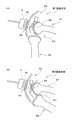
- It is a schematic diagram which shows the state of the knee joint at the time of ultrasonic transmission, Comprising: (A) shows the state (1st bending state) with the largest angle (flexion angle) between a femur and a tibia at the time of apparatus use. The figure shown, (B) is a figure which shows the state (2nd bending state) with the smallest bending angle.
- FIG. 1 It is a block diagram which shows an example of a structure of the analysis area
- FIG. 1 is a schematic diagram showing a configuration of an ultrasonic diagnostic apparatus 1 according to an embodiment of the present invention.
- the ultrasound diagnostic apparatus 1 is for diagnosing the state (degeneration degree) of the cartilage at the proximal end of the femur (first bone) in the patient's knee.
- the index indicating the degree of degeneration of the knee cartilage described above is calculated, as will be described in detail later, and the user (for example, a doctor) diagnoses the patient's knee cartilage from the index. Can do.
- the ultrasonic diagnostic apparatus 1 includes an operation unit 2, a control unit 3, a probe 4, a signal processing unit 10, and a display unit 5.
- the operation unit 2 is composed of, for example, a keyboard or a touch panel, and accepts user operation input.
- the operation unit 2 instructs the control unit 3 to start executing a process for detecting the cartilage surface in accordance with a user operation input.
- the operation unit 2 outputs an instruction to set or switch the display mode to the display unit 5 in accordance with a user operation input.
- the operation unit 2 may be incorporated in the display unit 5.
- the control unit 3 generates a pulsed ultrasonic signal and controls the probe 4 so that the ultrasonic signal is transmitted from the probe 4.
- the probe 4 includes a plurality of transducers 4b arranged in a direction parallel to the transmission / reception surface 4a (see FIG. 1).
- the direction in which the transducers 4b are arranged is the scanning direction (the X direction in FIG. 1, the direction perpendicular to the depth direction of the cartilage 52).
- Each transducer 4b is provided as an ultrasonic transmitter that transmits an ultrasonic signal toward the cartilage 52 at predetermined time intervals.
- Each transducer 4b is provided as an ultrasonic receiver that receives an echo signal of the transmitted ultrasonic signal.
- the probe 4 is such that the normal direction of the wave transmitting / receiving surface 4 a of the probe 4 is directed to the cartilage 52 of the femur 51 and from the proximal to the distal side of the femur 51. It is applied to the surface of the soft tissue 60 of the knee (that is, along the direction in which the femur 51 extends). Thereby, an ultrasonic wave is transmitted along the depth direction of the cartilage 52.
- the soft tissue 60 is a portion that exists on the surface side of the knee relative to the cartilage 52 of the femur 51, and is composed of skin, muscle, and the like.
- the cartilage 52 is attached to the subchondral bone 53, and the subchondral bone 53 is a tissue connected to the cancellous bone 54.
- FIG. 2 is a schematic diagram showing the state of the knee joint 50 during ultrasonic transmission.
- the ultrasonic diagnostic apparatus in the ultrasonic diagnostic apparatus 1, ultrasonic waves are transmitted from each transducer 4b in each of a plurality of bending states in which the bending angles of the tibia 55 (second bone portion) with respect to the femur 51 are different.
- the reflected wave of the transmitted ultrasonic wave is received by each transducer 4b.
- the echo signals obtained in each bent state are each output to the signal processing unit 10.
- each transducer 4b has a predetermined time. Send ultrasonic waves at intervals. Specifically, the doctor determines that the patient's knee state is repeated between the first bent state shown in FIG. 2 (A) and the second bent state shown in FIG. 2 (B). The part is bent and stretched at a predetermined cycle (for example, 10 seconds). During this time, each transducer 4b transmits an ultrasonic wave at a constant time interval and receives the ultrasonic echo signal transmitted in each bent state between the first bent state and the second bent state.
- a predetermined cycle for example, 10 seconds
- the probe 4 When the patient's lower knee is bent and stretched as described above, the probe 4 is fixed in a relative position with respect to the femur 51. Accordingly, when the knee is bent and stretched, the position of the cartilage 52 with respect to the probe 4 becomes substantially the same, whereas the position of the soft tissue 60 with respect to the probe 4 changes with a predetermined periodicity (with the predetermined period). .
- the signal processing unit 10 analyzes the state of the cartilage 52 based on the echo signal received by each transducer 4b as described above, and outputs the analysis result to the display unit 5. The detailed configuration and operation of the signal processing unit 10 will be described later in detail.
- the display unit 5 displays the analysis result of the cartilage 52 analyzed by the signal processing unit 10. Specifically, an echo image indicating the shape of the cartilage 52 is displayed on the display unit 5. Further, the display unit 5 displays the feature amount as an index indicating the state of the cartilage calculated by the signal processing unit 10. The user diagnoses the state of the cartilage 52 of the patient's knee from these echo images and feature quantities.
- FIG. 3 is a block diagram illustrating a configuration of the signal processing unit 10 of the ultrasonic diagnostic apparatus 1 according to the present embodiment.
- the signal processing unit 10 includes an echo signal receiving unit 11, an AD conversion unit 12, an analysis region setting unit 13, a three-dimensional DFT processing unit 14, an LPF processing unit 15, and a three-dimensional IDFT.
- a processing unit 16, an echo image generation unit 17, and a feature amount calculation unit 18 are provided.
- the signal processing unit 10 is configured using hardware including a CPU, a RAM, a ROM (not shown), and the like.
- the signal processing unit 10 is configured using software including a signal processing program stored in the ROM.
- the signal processing program is a program for causing the signal processing unit 10 to execute the signal processing method according to the embodiment of the present invention.
- This program can be installed externally.
- the installed program is distributed while being stored in a recording medium.
- the hardware and software are configured to operate in cooperation.
- the signal processing unit 10 can be caused to function as the above-described echo signal receiving unit 11, AD conversion unit 12, analysis region setting unit 13, and the like.
- the echo signal receiving unit 11 performs a predetermined amplification process on the echo signals obtained in each of the plurality of bent states described with reference to FIG.
- the AD conversion unit 12 converts the echo signal into discrete data by sampling at predetermined time intervals.
- the echo signal converted into discrete data becomes echo data.
- a plurality (two or more frames) of two-dimensional echo data specified by the scanning direction x and the depth direction z can be obtained. That is, the AD converter 12 can obtain three-dimensional echo data.
- the AD conversion unit 12 outputs the echo data to the analysis region setting unit 13.
- FIG. 4 is a block diagram showing an example of the configuration of the analysis area setting unit 13.
- the analysis area setting unit 13 sets an area excluding an echo signal from the subchondral bone 53 that is unnecessary for diagnosing the state of the cartilage 52 as an analysis area.
- the analysis region setting unit 13 includes an attention region setting unit 13a, an echo level difference calculation unit 13b, a determination unit 13c, and a setting unit 13d.
- FIG. 5 is an echo image based on the echo data output from the AD conversion unit 12, and is a diagram for explaining the setting of the region of interest.
- FIG. 5 is illustrated as an echo image of a region specified by the scanning direction of the probe 4 (x direction in FIG. 5) and the depth direction of the cartilage (z direction in FIG. 5).
- Region of interest R n is comprised of a first region R A and the second region R B.
- the first region RA is a region on the knee surface side in the region of interest R.
- the second region R B is a region of the first region R A depth direction than the (Z direction) is deeper side in the region of interest R, is a short region width in the depth direction than the first region R A .
- the attention area setting unit 13a sets the attention area R n a plurality of times while shifting the attention area R n by a predetermined interval toward the deep side in the depth direction.
- the echo level difference calculation unit 13b calculates an average value (first average value) of echo intensities of all samples in the first region and an average value (second average value) of echo intensities of all samples in the second region.
- the subtraction value is calculated by subtracting the second average value from the first average value.
- Determining unit 13c from a plurality of the subtraction values calculated for each region of interest R n which is set a plurality of times, to select the most value is less subtraction value, the subtracted value is calculated and determining a region of interest R N, and a subchondral bone area which is an area that includes the subchondral bone.
- the setting unit 13d sets a region excluding the subchondral bone region determined by the determination unit 13c, specifically, a rectangular region shallower than the subchondral bone region as the analysis region.
- the three-dimensional DFT processing unit 14 performs a three-dimensional DFT (Discrete Fourier Transformation) process on the echo data in the analysis region set by the analysis region setting unit 13. Thereby, the three-dimensional echo data including the data in the real space region and the time region can be converted into the three-dimensional echo data including the data in the wave number space region and the frequency region.
- the three-dimensional echo data is output to the LPF processing unit 15 and the feature amount calculation unit 18.
- the LPF processing unit 15 performs LPF processing (low-pass filter processing) in the frame direction on the three-dimensional echo data output from the three-dimensional DFT processing unit 14.
- LPF processing low-pass filter processing
- the echo signal of the soft tissue 60 having substantially the same period as the predetermined period can be removed from the echo signal of the cartilage 52 whose period is sufficiently smaller than the predetermined period.
- the data obtained by the LPF processing unit 15 is output to the three-dimensional IDFT processing unit 16 as low frequency echo data.
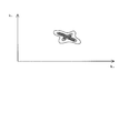
- This low-frequency echo data can be displayed as a power spectrum on the coordinates specified by the wave number kx in the x direction and the wave number kz in the z direction.
- the three-dimensional IDFT processing unit 16 performs an inverse Fourier transform on the low frequency echo data output from the LPF processing unit 15. Accordingly, the three-dimensional IDFT processing unit 16 converts the low frequency echo data, which is data in the wave number space domain and the frequency domain, into echo data in the real space.
- the three-dimensional DFT processing unit 14, the LPF processing unit 15, and the three-dimensional IDFT processing unit 16 described above are echo data having a frequency component lower than a predetermined frequency from the three-dimensional echo data output from the AD conversion unit 12. It functions as a low frequency component extraction unit that extracts low frequency echo data.
- FIG. 6 is a diagram illustrating an example of an echo image generated by the echo image generation unit 17.
- the echo image generation unit 17 generates an echo image from the echo data generated by the three-dimensional IDFT processing unit 16 in which the echo data of the soft tissue 60 is reduced.
- the echo image generation unit 17 of the present embodiment generates an echo level image based on echo data from each position in the analysis region set by the analysis region setting unit 13.
- the echo level image is composed of a plurality of pixels arranged in a grid pattern. Each pixel is arranged at a position corresponding to each position in the analysis area, and has a luminance level corresponding to the echo intensity at each position in the analysis area.
- the luminance level goes from higher to lower, for example, colors that gradually change in the order of red, orange, yellow, green, blue, and dark blue are displayed in association with each other.
- FIG. 6 for convenience, a region with a high luminance level is indicated by dark hatching, and a region with a low luminance level is indicated by thin hatching.
- the echo image is displayed on the display unit 5.
- FIG. 7 is a block diagram showing a configuration of the feature amount calculation unit.
- the feature amount calculation unit 18 is a feature amount that is an index indicating the feature of the echo data from the low-frequency echo data output from the LPF processing unit 15, that is, echo data mainly composed of echo data from the cartilage 52. Is calculated.
- the feature amount calculation unit 18 calculates a half-value width, which will be described in detail later, as the feature amount.
- the feature amount calculation unit 18 includes a power spectrum selection unit 18a, a spectrum angle characteristic calculation unit 18b, and a half-value width calculation unit 18c (angle width calculation unit).
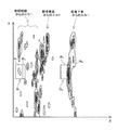
- FIG. 8 is a diagram showing a power spectrum of a low frequency component.
- the power spectrum selection unit 18a selects a power spectrum of a low frequency component from the power spectrum obtained from the three-dimensional echo data output from the three-dimensional DFT processing unit 14. That is, the power spectrum selection unit 18a selects a power spectrum mainly composed of echo data of the cartilage 52.
- FIG. 9 is a diagram for explaining a method for calculating the spectral angle characteristic from the power spectrum shown in FIG. 8, and FIG. 10 is a waveform showing an example of the spectral angle characteristic obtained by the method shown in FIG. It is.
- the spectrum angle characteristic calculation unit 18 b sets a target region R ⁇ that is a fan-shaped minute region centered on the center C (origin) of the power spectrum.
- the spectrum angle characteristic calculation unit 18b shifts the rotational position ⁇ of the target region R ⁇ in the range of 0 degrees to 180 degrees.
- Spectral angle characteristic calculation unit 18b in the region of interest R [Delta] [theta] of the rotational position ⁇ gradually shifted, adding the echo intensity of all points within each target region R [Delta] [theta].
- the spectral angle characteristic calculation unit 18b calculates the spectral angle characteristic shown in FIG. 10 by calculating the total value of the echo intensities corresponding to the respective rotational positions ⁇ .
- the total value of the echo intensity for each rotational position ⁇ is standardized.
- the present invention is not limited to this, and the above-described total value may be used as it is.
- the half-width calculator 18c calculates the half-width of the peak of the spectrum angle characteristic calculated by the spectrum angle characteristic calculator 18b. Specifically, the half-value width calculation unit 18c detects a peak value in a predetermined angle range near 90 degrees (for example, 80 degrees to 100 degrees as an example), and the half-value width of the peak waveform having the peak value (FIG. 10). In the example shown in FIG.
- the full width at half maximum is output and displayed on the display unit 5 as a feature amount that is an index indicating the degree of degeneration of the cartilage 52. In the present embodiment, the full width at half maximum is obtained from the spectral angle characteristic, but the present invention is not limited to this. Specifically, in the spectral angle characteristic, an angle width in which the total value is a predetermined ratio with respect to the peak value of the spectral angle characteristic may be calculated.
- FIG. 11 is an echo image of cartilage
- (A) shows an example of an echo image of normal cartilage
- (B) shows an example of an echo image of degenerated cartilage.
- FIG. 12 is an image of echo data obtained by inverse Fourier transform of the degenerated cartilage echo data shown in FIG.
- the echo image of cartilage shown in FIG. 11A is obtained by performing inverse Fourier transform on the echo data shown in FIG.
- the normal cartilage echo image is continuous along the scanning direction x of the probe 4. Therefore, when this is subjected to inverse Fourier transform, a directional power spectrum is generated (see FIG. 8). Therefore, the half-value width of the spectrum angle characteristic calculated from the power spectrum is relatively small as shown in FIG.
- the echo image of the degenerated cartilage is different from the echo image of the normal cartilage shown in FIG. 11 (A), and is continuous along the scanning direction x of the probe 4 as shown in FIG. 11 (B). Rather, it becomes discrete. Therefore, when this is subjected to inverse Fourier transform, a power spectrum with relatively small directivity is generated (see FIG. 12). Therefore, the half-value width of the spectrum angle characteristic calculated from the power spectrum is larger than the half-value width of the spectrum angle characteristic obtained from normal cartilage, as shown in FIG. In FIG. 13, a waveform indicated by a broken line is a spectral angle characteristic obtained from normal cartilage, and a waveform indicated by a solid line is a spectral angle characteristic obtained from degenerated cartilage.
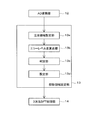
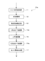
- FIG. 14 is a flowchart for explaining the operation of the signal processing unit 10. The operation of the signal processing unit 10 will be described with reference to FIG.
- step S1 the probe 4 is set on the patient's knee. At this time, the probe 4 is set with respect to the patient's knee so that the normal direction of the wave transmitting / receiving surface 4a is along the direction in which the femur 51 extends.
- step S2 referring to FIG. 2, the patient's knee is bent and stretched at a predetermined cycle between the first bent state and the second bent state.
- this bending and stretching is performed by, for example, a doctor swinging the patient's lower knee.
- the ultrasonic wave is transmitted and received by the transducer 4b of the probe 4 in step S3.
- the echo signal received by the transducer 4 b is subjected to a predetermined amplification process by the echo signal receiving unit 11 and then converted into a digital signal by the AD conversion unit 12.
- step S4 it is determined whether or not data necessary for the subsequent three-dimensional DFT processing has been acquired. Specifically, it is determined whether or not the necessary number (for example, 32 as an example) of echo data in a bent state is obtained.
- the process proceeds to step S5.
- the process returns to Step S2 and Step S3, and Steps S2 and S3 are performed again.
- step S5 an analysis area is set.
- the region of interest setting unit 13a sets a configured region of interest R 1 in the first region R A and the second region R B
- the echo level difference calculation unit 13b After calculating the average value (first average value and second average value) of the echo intensities of all the samples in the regions R A and R B , the subtraction value obtained by subtracting the second average value from the first average value is obtained. calculate.
- the subtraction value is calculated for each region of interest R n to be even by a predetermined distance to the deep direction.
- the determination unit 13c determines that the region of interest having the largest subtraction value is a subchondral bone region that includes the subchondral bone, and the setting unit 13d has a shallower side than the subchondral bone region. Set the rectangular area as the analysis area.
- step S6 three-dimensional DFT processing is performed on the echo data in the analysis region set in step S5 among the echo data of the knee joint corresponding to each of a plurality of flexion states. Thereby, three-dimensional echo data including data in the wave number space domain and the frequency domain can be obtained.
- step S7 the LPF processing unit 15 generates low frequency echo data by performing LPF processing on the three-dimensional echo data in the frame direction. Thereby, the echo signal from the soft tissue 60 can be reduced.
- step S8 the three-dimensional IDFT processing unit 16 performs inverse Fourier transform on the low-frequency echo data. Accordingly, the three-dimensional IDFT processing unit 16 converts the low frequency echo data, which is data in the wave number space domain and the frequency domain, into echo data in the real space.
- step S9 the echo image generation unit 17 generates an echo image from the low-frequency echo data generated by the three-dimensional IDFT processing unit 16 (that is, echo data in which the echo signal of the soft tissue 60 is reduced). (See FIG. 6).
- the echo image is displayed on the display unit 5 as information on cartilage.
- step S10 the feature amount calculation unit 18 performs a process of calculating a half width as a feature amount.
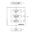
- FIG. 15 is a flowchart showing each step performed in step S10. With reference to FIG. 15, the step of calculating the feature amount will be described.
- the power spectrum selection unit 11a selects a power spectrum of a low frequency component from the power spectrum obtained from the three-dimensional echo data output from the three-dimensional DFT processing unit 14.
- the power spectrum selection unit 11a may select the power spectrum of the low frequency component from the power spectrum obtained from the low frequency echo data generated by the LPF processing unit 15.
- step S12 the spectrum angle characteristic calculation unit 18b sets a target region R ⁇ that is a fan-shaped minute region centered on the center C (origin) of the power spectrum (see FIG. 9).
- the target region R ⁇ where the rotation angle is 0 degree is set as an example.
- step S13 the spectrum angle characteristic calculation unit 18b calculates the total value by summing up the echo intensities at all points in the target region R ⁇ .
- step S14 the spectrum angle characteristic calculation unit 18b determines whether or not the total value has been calculated over the entire range in which the total value is to be calculated in the selected power spectrum. Specifically, the spectrum angle characteristic calculation unit 18b determines whether or not the rotation angle of the target region R ⁇ has reached 180 degrees. When the angle does not reach 180 degrees (No in step S14), the spectral angle characteristic calculation unit 18b shifts the position of the target region R ⁇ by rotating the target region R ⁇ by a predetermined angle in step S15, and newly The process of step S13 is performed again for the set target region R ⁇ . On the other hand, if the angle reaches 180 degrees (Yes in step S14), the process proceeds to step S16.
- step S16 the spectrum angle characteristic calculation unit 18b normalizes the total value calculated as described above. Specifically, the spectral angle characteristic calculation unit 18b detects the maximum value of each total value calculated for each rotation angle, calculates a coefficient such that the maximum value after normalization is 1, Multiply all other values by the factor. Thereby, a spectral angle characteristic can be obtained. Note that step S16 may be omitted, and step S17 may be performed after step S14.
- step S17 the half-value width calculation unit 18c obtains the half-value width of the spectrum angle characteristic.
- the said half value width is displayed on the display part 5 as a feature-value.
- a plurality of ultrasonic waves are transmitted while changing the bending angle of the tibia 55 with respect to the femur 51 while the relative position of the probe 4 with respect to the cartilage 52 is fixed.
- an echo signal of the cartilage 52 is obtained in each of a plurality of bent states.
- the echo resulting from the soft tissue 60 which is a high frequency component can be reduced by extracting a low frequency component from each echo signal obtained in each of the said some bending state. That is, unnecessary echoes (echoes from the soft tissue 60 in this embodiment) can be removed from desired echoes (echoes from the cartilage 52 in this embodiment). In this way, even if the difference in echo level between the desired echo and the unwanted echo is small, the unwanted echo can be reliably separated from the desired echo.
- the ultrasonic diagnostic apparatus 1 can accurately detect the shape of the cartilage 52.
- the ultrasonic diagnostic apparatus 1 based on the accurately detected shape of the cartilage 52, information on the cartilage 52 (in the case of the present embodiment, an echo image of the cartilage 52 and a half-value width as a feature amount of the cartilage 52 ) Can be derived. Therefore, the degree of cartilage degeneration can be diagnosed with higher accuracy.
- the ultrasonic diagnostic apparatus since ultrasonic waves are transmitted at predetermined time intervals to the knee joint that is bent and stretched at a predetermined cycle, an echo signal can be acquired smoothly in a relatively short time. it can.
- the cutoff frequency is set as a frequency lower than a cycle (0.1 Hz in the present embodiment) expressed as the reciprocal of the knee bending / extension cycle. Thereby, a cutoff frequency can be set appropriately.
- an echo image is generated as information on cartilage, so that a user (physician or the like) can diagnose the state of the cartilage from the echo image.
- the three-dimensional echo data specified by the frame direction, the cartilage depth direction (z direction), and the direction orthogonal to the depth direction (x direction) is Fourier transformed in the frame direction.
- the high-frequency component is removed from the three-dimensional echo data subjected to the Fourier transform by the low-pass filter unit. Thereby, the echo signal resulting from the soft tissue 60 can be appropriately removed from the three-dimensional echo data.
- the three-dimensional echo data is Fourier-transformed in all directions, and a low-frequency component (low-frequency two-dimensional echo data) in the frame direction is extracted from the Fourier-transformed three-dimensional echo data.
- a feature value (half-value width) is calculated based on the data.
- an area including the cartilage 52 and excluding the subchondral bone 53 is set as an analysis area, and three-dimensional Fourier transform is performed on an echo signal in the analysis area.
- a region unnecessary for calculating the feature amount (a region including the subchondral bone 53) can be removed, and the calculation load on the signal processing unit 10 can be reduced.
- the ultrasonic diagnostic apparatus 1 can diagnose the degree of degeneration of the cartilage 52 of the femur 51 for the knee joint including the proximal end of the femur 51 and the distal end of the tibia 55.
- the normal direction of the wave transmitting / receiving surface 4 a of the probe 4 is arranged along the direction toward the cartilage 52 and the femur 51 extends, so that it is appropriate along the depth direction of the cartilage 52. Can transmit ultrasonic waves.
- the feature amount (half-value width) calculated by the signal processing unit 10 is displayed on the display unit 5. Thereby, the user can visually recognize the feature amount as an index indicating the degree of degeneration of the cartilage 52.
- FIG. 16 is a block diagram showing a configuration of an ultrasonic diagnostic apparatus 1a according to a modification.
- the ultrasonic diagnostic apparatus 1a according to this modification includes an automatic knee bending mechanism 30 that can automatically change the bending state of the patient's knee.
- the configuration of the automatic knee bending mechanism 30 described below is merely an example, and any configuration may be used as long as the mechanism can automatically bend the patient's knee.
- portions that differ greatly from the above embodiment, specifically, the configuration and operation of the automatic knee bending mechanism 30 will be mainly described, and descriptions of other portions will be omitted.
- the automatic knee flexing mechanism 30 is configured to be able to swing a portion below the patient's knee (lower knee) in a state where the position of the femur is fixed while the patient is sitting on the chair. At this time, the relative position of the probe 4 with respect to the femur is fixed by a fixture (not shown) or the like. Thereby, the patient's knee is bent in a plurality of states by the automatic knee bending mechanism 30.
- the automatic knee bending mechanism 30 includes a base portion 31, a support column portion 32, and a swing mechanism 33.
- the base portion 31 is a substantially plate-like portion placed on the floor, and is formed of, for example, a relatively heavy metal material.
- the column part 32 is provided so as to extend upward from the base part 31 in a state of being installed on the floor. The column part 32 is fixed to the base part 31.
- the swing mechanism 33 is configured to swing the patient's lower knee in the front-rear direction.
- the swing mechanism 33 includes an electric motor 34, a footrest portion 35, and a connecting portion 36.
- the electric motor 34 is attached to the upper portion of the column portion 32.
- the footrest part 35 is formed in a substantially plate shape on which a patient's foot can be placed, and is supported on the upper surface of the base part 31.
- the patient's foot is fixed to the footrest 35 by a fixing belt 37.
- the connecting portion 36 is provided so as to extend in the vertical direction along the column portion, and the lower end portion is fixed to the footrest portion 35, and transmits the rotational force of the electric motor 34 to the footrest portion 35.
- the electric motor 34 bends and stretches the patient's knee at the predetermined cycle described above between the first bent state and the second bent state shown in FIG. Thus, it rotates forward or backward.
- ultrasonic waves are transmitted from each transducer 4b at predetermined time intervals.
- FIG. 17 is a block diagram showing a configuration of the signal processing unit 10a of the ultrasonic diagnostic apparatus according to the modification.
- Fourier transform is performed for all directions on the three-dimensional echo data specified by the frame direction, the cartilage depth direction, and the direction orthogonal to both the frame direction and the depth direction (
- the present invention is not limited to this, and the Fourier transform may be performed only in the frame direction.
- the calculation load concerning the signal processing part 10a can be reduced.
- an echo image is generated as information about cartilage, for example.
- FIG. 18 is a block diagram showing a configuration of the signal processing unit 10b of the ultrasonic diagnostic apparatus according to the modification.
- the signal processing unit 10b according to this modification includes an echo signal receiving unit 11, an AD conversion unit 12, a low frequency component extraction unit 19, and a derivation unit 20.
- the low frequency component extraction unit 19 extracts low frequency echo data, which is echo data having a frequency component lower than a predetermined frequency, from the three-dimensional echo data.
- the low frequency component extraction unit 19 extracts low frequency echo data by using a technique such as LPF processing (low pass filter processing), wavelet transform, convolution, and the like.
- the wavelet transform is one of frequency analysis methods and uses a wavelet function as a basis function.
- the convolution a function obtained by performing an inverse Fourier transform on the transfer function used in the low-pass filter processing in the above embodiment is convolved with the three-dimensional echo data.
- the derivation unit 20 derives information on cartilage based on the low frequency echo data extracted by the low frequency component extraction unit 19.
- the information on the cartilage includes not only the echo image and the half-value width exemplified in the above embodiment, but also other information.
- the ultrasonic diagnostic apparatus is applied to the femoral cartilage.
- the present invention is not limited thereto, and the ultrasonic diagnostic apparatus according to the present invention is applicable to other cartilage. Can be applied.
- the echo image and the full width at half maximum are displayed on the display unit 5 as information on cartilage.
- the present invention is not limited to this, and the power spectrum selected by the power spectrum selection unit 18a is displayed on the display unit 5. It may be displayed.
Landscapes
- Engineering & Computer Science (AREA)
- Health & Medical Sciences (AREA)
- Physics & Mathematics (AREA)
- Life Sciences & Earth Sciences (AREA)
- Radar, Positioning & Navigation (AREA)
- Remote Sensing (AREA)
- Public Health (AREA)
- Medical Informatics (AREA)
- Computer Networks & Wireless Communication (AREA)
- General Physics & Mathematics (AREA)
- Biomedical Technology (AREA)
- General Health & Medical Sciences (AREA)
- Pathology (AREA)
- Nuclear Medicine, Radiotherapy & Molecular Imaging (AREA)
- Animal Behavior & Ethology (AREA)
- Veterinary Medicine (AREA)
- Surgery (AREA)
- Molecular Biology (AREA)
- Heart & Thoracic Surgery (AREA)
- Radiology & Medical Imaging (AREA)
- Biophysics (AREA)
- Acoustics & Sound (AREA)
- Orthopedic Medicine & Surgery (AREA)
- Rheumatology (AREA)
- Computer Vision & Pattern Recognition (AREA)
- Physiology (AREA)
- Data Mining & Analysis (AREA)
- Primary Health Care (AREA)
- Epidemiology (AREA)
- Databases & Information Systems (AREA)
- Ultra Sonic Daignosis Equipment (AREA)
Abstract
Description
よりも低い周波数として設定されている。
抽出するステップと、前記低周波エコーデータに基づいて前記軟骨に関する情報を導出するステップと、を更に含む。
超音波診断装置1は、図1に示すように、操作部2と、制御部3と、プローブ4と、信号処理部10と、表示部5と、を備えている。
ザは、これらのエコー画像及び特徴量から、患者の膝の軟骨52の状態を診断する。
図3は、本実施形態に係る超音波診断装置1の信号処理部10の構成を示すブロック図である。信号処理部10は、図3に示すように、エコー信号受信部11と、AD変換部12と、解析領域設定部13と、3次元DFT処理部14と、LPF処理部15と、3次元IDFT処理部16と、エコー画像生成部17と、特徴量算出部18と、を備えている。信号処理部10は、CPU、RAM及びROM(図示せず)等を含むハードウェアを用いて構成されている。また、信号処理部10は、ROMに記憶された信号処理プログラムを含むソフトウェアを用いて構成されている。
する。
ここで、上述のように算出される半値幅と、軟骨52との変性度合との関係性について説明する。
スペクトルが生成される(図8参照)。よって、当該パワースペクトルから算出されるスペクトル角度特性の半値幅は、図10に示すように、比較的小さくなる。
図14は、信号処理部10の動作を説明するためのフローチャートである。図14を参照して、信号処理部10の動作について説明する。
以上のように、本実施形態に係る超音波診断装置1では、軟骨52に対するプローブ4の相対位置が固定された状態で大腿骨51に対する脛骨55の屈曲角度を変化させつつ、超音波を複数のタイミングで送信することにより、複数の屈曲状態のそれぞれにおいて、軟骨52のエコー信号が得られる。そして、当該複数の屈曲状態のそれぞれにおいて得られた各エコー信号のうち低周波成分を抽出することにより、高周波成分である軟部組織60に起因するエコーを低減できる。すなわち、所望のエコー(本実施形態の場合、軟骨52からのエコー)から、不要なエコー(本実施形態の場合、軟部組織60からのエコー)を除去できる。こうすると、所望のエコーと不要なエコーとの間のエコーレベルの差が小さい場合であっても、不要なエコーを所望のエコーから確実に分離することができる。
かい且つ大腿骨51が延びる方向に沿って配置されるため、軟骨52の深さ方向に沿って適切に超音波を送信することができる。
(1)図16は、変形例に係る超音波診断装置1aの構成を示すブロック図である。上記実施形態では、医師等によって、患者の膝の屈曲状態が変更させられた。しかし、本変形例に係る超音波診断装置1aは、上述した実施形態と異なり、患者の膝の屈曲状態を自動で変更可能な自動膝屈曲機構30を備えている。なお、以下で説明する自動膝屈曲機構30の構成は、一例であって、患者の膝を自動で屈曲可能な機構であれば、どのような構成であってもよい。また、以下では、上記実施形態と大きく異なる部分、具体的には、自動膝屈曲機構30の構成及び動作について主に説明し、それ以外の部分については説明を省略する。
4 プローブ
4a 送受波面
4b 振動子(超音波送信部、超音波受信部)
17 エコー画像生成部(導出部)
18 特徴量算出部(導出部)
19 低周波成分抽出部
20 導出部
50 膝関節(関節部)
51 大腿骨(第1の骨部)
52 (第1の骨部の)軟骨
55 脛骨(第2の骨部)
60 軟部組織
Claims (11)
- 第1の骨部の端部と第2の骨部の端部とを含む関節部を覆う軟部組織を介して、前記第1の骨部の端部の軟骨に向かって超音波を送信する超音波送信部と、該超音波送信部から送信された超音波のエコー信号を受信する超音波受信部と、を備え、該超音波受信部で受信された前記エコー信号に基づいて前記軟骨の変性度を診断するための超音波診断装置であって、
前記超音波送信部は、前記超音波の送受信が行われる送受波面の前記軟骨に対する相対位置が固定された状態における、前記第1の骨部に対する前記第2の骨部の屈曲角度が異なる複数の屈曲状態のそれぞれにおいて、前記軟骨に超音波を送信し、
前記超音波受信部は、前記複数の屈曲状態のそれぞれにおいて、前記軟骨の深さ方向と該深さ方向に直交する方向とで特定される各フレームにおけるエコー信号を受信し、
前記超音波受信部で受信されたエコー信号から、複数の前記フレームの整列方向であるフレーム方向について、所定周波数より低い周波数成分のエコーデータである低周波エコーデータを抽出する低周波成分抽出部と、
前記低周波成分抽出部で抽出された前記低周波エコーデータに基づいて、前記軟骨に関する情報を導出する導出部と、
を更に備えていることを特徴とする、超音波診断装置。 - 請求項1に記載の超音波診断装置において、
前記第2の骨部は、前記複数の屈曲状態のうち前記屈曲角度が最も大きい第1屈曲状態と、前記屈曲角度が最も小さい第2屈曲状態との間において、所定周期で屈曲動作を行い、
前記超音波送信部は、所定の時間間隔で超音波を送信することを特徴とする、超音波診断装置。 - 請求項2に記載の超音波診断装置において、
前記所定周波数は、前記所定周期の逆数として表される周波数よりも低い周波数として設定されていることを特徴とする、超音波診断装置。 - 請求項1から請求項3のいずれか1項に記載の超音波診断装置において、
前記導出部は、前記低周波エコーデータに基づいて、前記軟骨に関する情報としてのエコー画像を生成するエコー画像生成部を有していることを特徴とする、超音波診断装置。 - 請求項1から請求項4のいずれか1項に記載の超音波診断装置において、
前記低周波成分抽出部は、
前記フレーム方向に整列した前記フレーム毎のエコーデータで構成され、前記フレーム方向、前記軟骨の深さ方向、及び、前記フレーム方向及び前記深さ方向の両方に直交する方向、で特定される3次元エコーデータ、に対して、少なくとも前記フレーム方向にフーリエ変換を行うフーリエ変換部と、
前記フーリエ変換部でフーリエ変換が行われた前記3次元エコーデータから前記低周波エコーデータを抽出するローパスフィルタ部と、
を有していることを特徴とする、超音波診断装置。 - 請求項5に記載の超音波診断装置において、
前記フーリエ変換部は、前記3次元エコーデータに対して3次元フーリエ変換を行い、
前記導出部は、
前記フーリエ変換部でフーリエ変換された前記3次元エコーデータから、前記フレーム方向における低周波の2次元エコーデータである低周波2次元エコーデータを選択する選択部と、
前記選択部で選択された前記低周波2次元エコーデータにおける原点を通過する基準線に対して設定される複数の角度位置のそれぞれに対応する領域内のエコー強度を合計して合計値を算出し、各前記角度位置に対する各前記合計値をスペクトル角度特性として算出するスペクトル角度特性算出部と、
前記スペクトル角度特性算出部で算出された前記スペクトル角度特性において、前記合計値が、前記スペクトル角度特性のピーク値に対する所定の割合となる角度の幅を算出する角度幅算出部と、
を有していることを特徴とする、超音波診断装置。 - 請求項6に記載の超音波診断装置において、
前記フレーム毎のエコーデータのいずれか1つにおいて、前記軟骨の深さ方向及び該深さ方向に直交する方向で特定され、前記軟骨を含み且つ該軟骨が付着する軟骨下骨を除く領域である解析領域、を設定する解析領域設定部を更に備え、
前記選択部は、前記解析領域設定部で設定された前記解析領域内に含まれる前記低周波2次元エコーデータを選択することを特徴とする、超音波診断装置。 - 請求項1から請求項7のいずれか1項に記載の超音波診断装置において、
前記第1の骨部としての大腿骨、及び前記第2の骨部としての脛骨、に対して用いられることを特徴とする、超音波診断装置。 - 請求項8に記載の超音波診断装置において、
前記送受波面は、法線方向が、前記軟骨に向かい且つ該大腿骨が延びる方向に沿って配置されることを特徴とする、超音波診断装置。 - 請求項1から請求項9のいずれか1項に記載の超音波診断装置において、
前記導出部で導出された前記軟骨に関する情報が表示される表示部、を更に備えていることを特徴とする、超音波診断装置。 - 第1の骨部の端部と第2の骨部の端部とを含む関節部を覆う軟部組織を介して、前記第1の骨部の端部の軟骨に向かって超音波を送信するステップと、前記超音波を送信するステップで送信された超音波のエコー信号を受信するステップと、を含み、前記エコー信号を受信するステップで受信された前記エコー信号に基づいて前記軟骨の変性度を診断するための超音波診断方法であって、
前記超音波を送信するステップでは、前記超音波の送受信が行われる送受波面の前記軟骨に対する相対位置が固定された状態における、前記第1の骨部に対する前記第2の骨部の屈曲角度が異なる複数の屈曲状態のそれぞれにおいて、前記軟骨に超音波が送信され、
前記エコー信号を受信するステップでは、前記複数の屈曲状態のそれぞれにおいて前記軟骨の深さ方向と該深さ方向と交差する方向とで特定される各フレームにおけるエコー信号が受信され、
複数の前記フレームの整列方向であるフレーム方向について、所定周波数より低い周波数成分のエコーデータである低周波エコーデータを抽出するステップと、
前記低周波エコーデータに基づいて前記軟骨に関する情報を導出するステップと、
を更に含むことを特徴とする、超音波診断方法。
Priority Applications (3)
| Application Number | Priority Date | Filing Date | Title |
|---|---|---|---|
| US15/124,907 US10568604B2 (en) | 2014-03-12 | 2015-02-26 | Method and device for ultrasonic diagnosis |
| CN201580013303.XA CN106102591B (zh) | 2014-03-12 | 2015-02-26 | 超声波诊断装置、以及超声波诊断方法 |
| JP2016507440A JP6278577B2 (ja) | 2014-03-12 | 2015-02-26 | 超音波診断装置、及び指標算出方法 |
Applications Claiming Priority (2)
| Application Number | Priority Date | Filing Date | Title |
|---|---|---|---|
| JP2014048884 | 2014-03-12 | ||
| JP2014-048884 | 2014-03-12 |
Publications (1)
| Publication Number | Publication Date |
|---|---|
| WO2015137131A1 true WO2015137131A1 (ja) | 2015-09-17 |
Family
ID=54071579
Family Applications (1)
| Application Number | Title | Priority Date | Filing Date |
|---|---|---|---|
| PCT/JP2015/055567 Ceased WO2015137131A1 (ja) | 2014-03-12 | 2015-02-26 | 超音波診断装置、及び超音波診断方法 |
Country Status (4)
| Country | Link |
|---|---|
| US (1) | US10568604B2 (ja) |
| JP (1) | JP6278577B2 (ja) |
| CN (1) | CN106102591B (ja) |
| WO (1) | WO2015137131A1 (ja) |
Cited By (4)
| Publication number | Priority date | Publication date | Assignee | Title |
|---|---|---|---|---|
| JP2017086255A (ja) * | 2015-11-05 | 2017-05-25 | 国立大学法人佐賀大学 | 関節炎症検出装置 |
| WO2017094397A1 (ja) * | 2015-12-04 | 2017-06-08 | 古野電気株式会社 | 超音波解析装置、超音波解析方法及び超音波解析プログラム |
| WO2017110361A1 (ja) * | 2015-12-25 | 2017-06-29 | 古野電気株式会社 | 超音波解析装置、超音波解析方法、および超音波解析プログラム |
| JP2019208971A (ja) * | 2018-06-07 | 2019-12-12 | 古野電気株式会社 | 超音波解析装置、超音波解析方法および超音波解析プログラム |
Families Citing this family (2)
| Publication number | Priority date | Publication date | Assignee | Title |
|---|---|---|---|---|
| ES2597780T3 (es) * | 2014-04-09 | 2017-01-23 | Magcam Nv | Dispositivos y métodos para determinar un campo magnético |
| CN114487117B (zh) * | 2022-02-18 | 2023-08-04 | 浙江大学 | 一种超声相控阵全矩阵数据非递归高效成像方法 |
Citations (4)
| Publication number | Priority date | Publication date | Assignee | Title |
|---|---|---|---|---|
| WO2008108054A1 (ja) * | 2007-03-05 | 2008-09-12 | Yamaguchi University | 超音波診断装置 |
| JP2010000125A (ja) * | 2008-06-18 | 2010-01-07 | Aloka Co Ltd | 超音波診断装置 |
| JP2010017369A (ja) * | 2008-07-11 | 2010-01-28 | Aloka Co Ltd | 人工関節検索装置 |
| JP2011125757A (ja) * | 2011-03-30 | 2011-06-30 | Hitachi Aloka Medical Ltd | 超音波画像データ処理装置 |
Family Cites Families (16)
| Publication number | Priority date | Publication date | Assignee | Title |
|---|---|---|---|---|
| US4932415A (en) * | 1988-11-14 | 1990-06-12 | Vingmed Sound A/S | Method of color coding two dimensional ulltrasonic doppler velocity images of blood flow on a display |
| US5458130A (en) * | 1992-07-30 | 1995-10-17 | Orthologic Corporation | Ultrasonic therapy and assessment apparatus and method |
| US6585666B2 (en) | 1998-10-13 | 2003-07-01 | The Administrators Of The Tulane Educational Fund | Arthroscopic diagnostic probe to measure mechanical properties of articular cartilage |
| JP2002345821A (ja) * | 2001-05-29 | 2002-12-03 | Koji Hattori | 関節腔内の超音波解析システム |
| EP1418835A2 (en) * | 2001-07-24 | 2004-05-19 | Sunlight Medical, Ltd. | Method and apparatus for bone diagnosis |
| US8623026B2 (en) * | 2006-02-06 | 2014-01-07 | Conformis, Inc. | Patient selectable joint arthroplasty devices and surgical tools incorporating anatomical relief |
| WO2009042644A2 (en) * | 2007-09-25 | 2009-04-02 | Perception Raisonnement Action En Medecine | Methods and apparatus for assisting cartilage diagnostic and therapeutic procedures |
| WO2010062638A2 (en) * | 2008-10-28 | 2010-06-03 | Washington University In St. Louis | Applying renyi entropy to detect changes in scattering architecture |
| US8444564B2 (en) * | 2009-02-02 | 2013-05-21 | Jointvue, Llc | Noninvasive diagnostic system |
| US20130211259A1 (en) * | 2009-02-02 | 2013-08-15 | Jointvue, Llc | Determination of joint condition based on vibration analysis |
| JP5377166B2 (ja) * | 2009-09-01 | 2013-12-25 | 古野電気株式会社 | 超音波骨解析装置 |
| JP5467987B2 (ja) * | 2010-11-18 | 2014-04-09 | 古野電気株式会社 | 超音波軟骨解析装置、超音波軟骨解析方法及びプログラム |
| JP5773781B2 (ja) * | 2011-06-30 | 2015-09-02 | 株式会社東芝 | 超音波診断装置、画像処理装置及びプログラム |
| JP5408399B1 (ja) * | 2012-03-23 | 2014-02-05 | コニカミノルタ株式会社 | 画像生成装置 |
| JP5840780B2 (ja) * | 2012-07-17 | 2016-01-06 | 古野電気株式会社 | 超音波測定器具および超音波測定装置 |
| JP6190374B2 (ja) * | 2012-09-19 | 2017-08-30 | 古野電気株式会社 | 軟組織軟骨境界面検出方法、軟組織軟骨境界面検出装置、および軟組織軟骨境界面検出プログラム |
-
2015
- 2015-02-26 CN CN201580013303.XA patent/CN106102591B/zh not_active Expired - Fee Related
- 2015-02-26 JP JP2016507440A patent/JP6278577B2/ja not_active Expired - Fee Related
- 2015-02-26 US US15/124,907 patent/US10568604B2/en active Active
- 2015-02-26 WO PCT/JP2015/055567 patent/WO2015137131A1/ja not_active Ceased
Patent Citations (4)
| Publication number | Priority date | Publication date | Assignee | Title |
|---|---|---|---|---|
| WO2008108054A1 (ja) * | 2007-03-05 | 2008-09-12 | Yamaguchi University | 超音波診断装置 |
| JP2010000125A (ja) * | 2008-06-18 | 2010-01-07 | Aloka Co Ltd | 超音波診断装置 |
| JP2010017369A (ja) * | 2008-07-11 | 2010-01-28 | Aloka Co Ltd | 人工関節検索装置 |
| JP2011125757A (ja) * | 2011-03-30 | 2011-06-30 | Hitachi Aloka Medical Ltd | 超音波画像データ処理装置 |
Cited By (11)
| Publication number | Priority date | Publication date | Assignee | Title |
|---|---|---|---|---|
| JP2017086255A (ja) * | 2015-11-05 | 2017-05-25 | 国立大学法人佐賀大学 | 関節炎症検出装置 |
| WO2017094397A1 (ja) * | 2015-12-04 | 2017-06-08 | 古野電気株式会社 | 超音波解析装置、超音波解析方法及び超音波解析プログラム |
| JPWO2017094397A1 (ja) * | 2015-12-04 | 2018-09-20 | 古野電気株式会社 | 超音波解析装置、超音波解析方法及び超音波解析プログラム |
| CN108601584A (zh) * | 2015-12-04 | 2018-09-28 | 古野电气株式会社 | 超声波解析装置、超声波解析方法及超声波解析程序 |
| CN108601584B (zh) * | 2015-12-04 | 2021-05-28 | 古野电气株式会社 | 超声波解析装置、超声波解析方法及存储介质 |
| WO2017110361A1 (ja) * | 2015-12-25 | 2017-06-29 | 古野電気株式会社 | 超音波解析装置、超音波解析方法、および超音波解析プログラム |
| JPWO2017110361A1 (ja) * | 2015-12-25 | 2018-10-04 | 古野電気株式会社 | 超音波解析装置、超音波解析方法、および超音波解析プログラム |
| CN108697408A (zh) * | 2015-12-25 | 2018-10-23 | 古野电气株式会社 | 超声波解析装置、超声波解析方法及超声波解析程序 |
| CN108697408B (zh) * | 2015-12-25 | 2021-10-26 | 古野电气株式会社 | 超声波解析装置、超声波解析方法及存储介质 |
| JP2019208971A (ja) * | 2018-06-07 | 2019-12-12 | 古野電気株式会社 | 超音波解析装置、超音波解析方法および超音波解析プログラム |
| JP7107522B2 (ja) | 2018-06-07 | 2022-07-27 | 古野電気株式会社 | 超音波解析装置、超音波解析方法および超音波解析プログラム |
Also Published As
| Publication number | Publication date |
|---|---|
| US20170035386A1 (en) | 2017-02-09 |
| CN106102591A (zh) | 2016-11-09 |
| CN106102591B (zh) | 2019-03-26 |
| JP6278577B2 (ja) | 2018-02-14 |
| JPWO2015137131A1 (ja) | 2017-04-06 |
| US10568604B2 (en) | 2020-02-25 |
Similar Documents
| Publication | Publication Date | Title |
|---|---|---|
| US12036067B2 (en) | Ultrasound diagnostic system, ultrasound image generation apparatus, and ultrasound image generation method | |
| JP6278577B2 (ja) | 超音波診断装置、及び指標算出方法 | |
| US10959704B2 (en) | Ultrasonic diagnostic apparatus, medical image processing apparatus, and medical image processing method | |
| JP6367425B2 (ja) | 超音波診断装置 | |
| EP3563769B1 (en) | Method and ultrasound system for shear wave elasticity imaging | |
| US11612381B2 (en) | Method for tissue characterization by ultrasound wave attenuation measurements and ultrasound system for tissue characterization | |
| US11123044B2 (en) | Signal processing device, ultrasonic diagnostic apparatus, and method | |
| US20130317361A1 (en) | Ultrasound diagnostic apparatus and method | |
| EP2905633B1 (en) | Ultrasonic diagnosis apparatus, image processing apparatus, and image processing method | |
| US10101450B2 (en) | Medical image processing apparatus, a medical image processing method and a medical diagnosis apparatus | |
| JP2020531074A (ja) | 画像アーチファクト特定及び除去のための深層学習ネットワークを有する超音波システム | |
| US20120310086A1 (en) | Ultrasonic diagnostic device, and method for measuring intima-media thickness | |
| JP6469876B2 (ja) | 超音波撮像装置及び超音波信号処理方法 | |
| JP6460707B2 (ja) | 超音波診断装置、超音波画像処理装置及び超音波画像処理プログラム | |
| CN106691502B (zh) | 用于生成弹性图像的超声系统和方法 | |
| JP2016027842A (ja) | 超音波治療装置 | |
| JP6212160B1 (ja) | 超音波診断装置 | |
| US20210161511A1 (en) | Ultrasonic diagnostic apparatus | |
| JP5690420B1 (ja) | 超音波診断装置 | |
| JP7828231B2 (ja) | 超音波時系列データ処理装置及び超音波時系列データ処理プログラム | |
| JP6780509B2 (ja) | 超音波診断装置の制御装置、超音波診断装置およびクラッター成分低減方法 | |
| JP2008279110A (ja) | 超音波診断装置及び血流情報観測装置 | |
| JP6444519B2 (ja) | 超音波診断装置、及び超音波撮像方法 | |
| JP2010193945A (ja) | 超音波診断装置 |
Legal Events
| Date | Code | Title | Description |
|---|---|---|---|
| 121 | Ep: the epo has been informed by wipo that ep was designated in this application |
Ref document number: 15761592 Country of ref document: EP Kind code of ref document: A1 |
|
| ENP | Entry into the national phase |
Ref document number: 2016507440 Country of ref document: JP Kind code of ref document: A |
|
| WWE | Wipo information: entry into national phase |
Ref document number: 15124907 Country of ref document: US |
|
| NENP | Non-entry into the national phase |
Ref country code: DE |
|
| 122 | Ep: pct application non-entry in european phase |
Ref document number: 15761592 Country of ref document: EP Kind code of ref document: A1 |