WO2015136863A1 - 駐車支援装置 - Google Patents
駐車支援装置 Download PDFInfo
- Publication number
- WO2015136863A1 WO2015136863A1 PCT/JP2015/000914 JP2015000914W WO2015136863A1 WO 2015136863 A1 WO2015136863 A1 WO 2015136863A1 JP 2015000914 W JP2015000914 W JP 2015000914W WO 2015136863 A1 WO2015136863 A1 WO 2015136863A1
- Authority
- WO
- WIPO (PCT)
- Prior art keywords
- vehicle
- parking
- parked
- inter
- target space
- Prior art date
- Legal status (The legal status is an assumption and is not a legal conclusion. Google has not performed a legal analysis and makes no representation as to the accuracy of the status listed.)
- Ceased
Links
Images



Classifications
-
- B—PERFORMING OPERATIONS; TRANSPORTING
- B62—LAND VEHICLES FOR TRAVELLING OTHERWISE THAN ON RAILS
- B62D—MOTOR VEHICLES; TRAILERS
- B62D15/00—Steering not otherwise provided for
- B62D15/02—Steering position indicators ; Steering position determination; Steering aids
- B62D15/027—Parking aids, e.g. instruction means
- B62D15/028—Guided parking by providing commands to the driver, e.g. acoustically or optically
Definitions
- This disclosure relates to a parking assistance device.
- the relative position and length of the parking space with respect to the vehicle is measured using an ultrasonic sensor, radar sensor, or in-vehicle camera, or the driving work necessary for parking is instructed, or Techniques for automatic execution are known. For example, a method of obtaining a parking space in which the measured parking space length is classified into three categories, “impossible to park”, “possible to park but difficult”, and “possible and easy to park”, based on a threshold that takes into account the driver's driving skills, and displays it to the driver Has been proposed (see Patent Document 1).
- Patent Document 1 whether or not parking is possible is determined based only on the relative relationship between the length of the parking target space and the length of the host vehicle, and therefore a parking space cannot be secured in a congested area such as a city center.
- Patent Document 2 an inter-vehicle communication device is required, and a vehicle not equipped with the device cannot be moved.
- the present disclosure has been made in view of the above points, and an object of the present disclosure is to provide a parking assistance device that can reduce loss of parking opportunities with a simple configuration.
- the parking assist device reflects the presence of a surrounding state acquisition unit that acquires the surrounding state of the host vehicle, and four parked vehicles in which the surrounding state is aligned along the traveling direction of the host vehicle.
- the detection part which detects the inter-vehicle distance of each of the four parked vehicles, and the inter-vehicle distance and the vehicle length of the own vehicle, the predetermined two of the four vehicles are parked.
- the determination part which determines whether it can park in the parking object space formed between vehicles, and the output part which outputs the result of determination as parking assistance information are provided.
- the above configuration enables parking with higher density and efficiency than before, and can reduce loss of parking opportunities.
- FIG. 1 is a diagram illustrating a configuration of a parking assistance device according to an embodiment of the present disclosure.
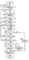
- FIG. 2 is a flowchart for explaining the parking support process.
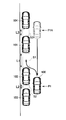
- FIG. 3 is a diagram for explaining parking support processing.
- FIG. 4 is a diagram showing a display example of the display unit at the time of forward parking assistance,
- FIG. 5 is a diagram illustrating a display example of the display unit during backward parking assistance.
- the parking assist device 1 of the present disclosure includes a well-known CPU 11 and peripheral circuits, a control program executed by the CPU 11 and a memory 12 that stores data necessary for control, and a signal input for exchanging signals with the outside.
- An output circuit (I / O) 13 is included.
- the CPU 11 functions as a detection unit (DETC) 11A, a determination unit (DETM) 11B, and a calculation unit (CALC) 11C of the present disclosure
- the I / O 13 includes an ambient state acquisition unit (SR ACQR) 13A of the present disclosure and an output unit (OUT) Functions as 13B.
- SR ACQR ambient state acquisition unit
- OUT output unit
- the parking assistance device 1 is connected to an ambient state detection unit 21, a vehicle state detection unit 22, an operation unit 23, and a display unit 24.
- the surrounding state detection unit 21 detects the surrounding state of the host vehicle including, for example, vehicles and objects around the host vehicle, the inter-vehicle distance, and the like.
- the ambient state detection unit 21 uses at least one of a camera, a radar, an ultrasonic sensor, and an infrared sensor.
- the camera includes an image processing unit, performs known image processing on the captured image data, and detects a vehicle or an object around the host vehicle.
- the radar detects an object existing around the host vehicle, and discriminates the vehicle and the object from the size of the object and the movement state (speed, direction).
- the ultrasonic sensor performs the same operation as the radar.
- the infrared sensor detects a vehicle and an object around the own vehicle based on the detected temperature of the heat source.
- the parking assistance device 1 acquires the surrounding state from the surrounding state detection unit 21 via the I / O 13.
- the surrounding state detection unit 21 may detect a parked vehicle and an object, measure the distance between the parked vehicles (details will be described later), and the parking assist device 1 may obtain an execution result.
- Each detection result in 21 may be acquired, and based on these, the parking assistance device 1 may detect a parked vehicle and an object, and measure the distance between the parked vehicles.
- the vehicle state detection unit 22 detects the state of the host vehicle.
- the vehicle state detection unit 22 uses at least one of a vehicle speed sensor, a steering angle sensor, a shift position sensor, a navigation device, a direction indicator, and a camera.
- the vehicle speed sensor detects the speed of the host vehicle.
- the steering angle sensor detects the steering angle of the steering handle of the host vehicle.
- the shift position sensor detects the position of the shift lever of the host vehicle.
- the navigation device searches for a guidance route from the current position of the host vehicle to the set destination and performs route guidance.
- the direction indicator detects the traveling direction of the host vehicle based on the state of the direction indicator.
- the camera includes an image processing unit, enables at least the driver's face to be photographed, performs known image processing on the photographed image data, and detects the driver's line-of-sight direction.
- the operation unit 23 uses a known mechanical switch or a touch panel formed on the display screen of the display unit 24.
- the parking assistance device 1 acquires the operation state of the operation unit 23 via the I / O 13.
- the display unit 24 uses a well-known LCD. Moreover, you may use the display part of a navigation apparatus or a meter apparatus (not shown).
- the parking assistance device 1 outputs parking assistance information to the display unit 24 via the I / O 13.
- the parking support information is data for displaying whether or not parking is possible in the parking space, a recommended traveling direction, and a recommended parking start position.
- parking is performed in parallel at the left end of the road in the order of parked vehicles (hereinafter abbreviated as “vehicles”) 104, 101, 102, 103 from the top.
- vehicle parked vehicles
- the host vehicle 100 is moving forward on the right side of these parked vehicles.
- the inter-vehicle distance between the vehicle 104 and the vehicle 101 is L3, the inter-vehicle distance between the vehicle 101 and the vehicle 102 is L1, and the inter-vehicle distance between the vehicle 102 and the vehicle 103 is L2.
- the vehicle 101 corresponds to the first parked vehicle of the present disclosure
- the vehicle 102 corresponds to the second parked vehicle of the present disclosure
- the vehicle 103 corresponds to the third parked vehicle of the present disclosure
- the vehicle 104 This corresponds to the disclosed fourth parked vehicle.
- the inter-vehicle distance L1 corresponds to the first inter-vehicle distance of the present disclosure
- the inter-vehicle distance L2 corresponds to the second inter-vehicle distance of the present disclosure
- the inter-vehicle distance L3 corresponds to the third inter-vehicle distance of the present disclosure.
- a space formed between the vehicle 104 and the vehicle 101 is S3, a space formed between the vehicle 101 and the vehicle 102 is S1, and a space formed between the vehicle 102 and the vehicle 103 is S2. To do.
- the space S1 corresponds to the parking target space of the present disclosure.
- the four parked vehicles are arranged in the order of the fourth parked vehicle 104, the first parked vehicle 101, the second parked vehicle 102, and the third parked vehicle 103 from the top, and the inter-vehicle distance is the fourth parked vehicle.
- the parking target space S1 is formed between the first parked vehicle and the second parked vehicle.
- the four parked vehicles make a determination only when the central space among the three spaces formed between the vehicles, that is, the parking target space is wider than the other two spaces, the own vehicle When 100 parks, the effort which expands parking object space back and forth can be reduced.
- the first state is when the vehicle speed is below a predetermined value for a predetermined time, for example, when the vehicle is slowly searching for a parking place.
- the second state is when traveling near the destination on the guide route.
- the third state is when the turn indicator is used at a place other than the right / left turn point on the guide route.
- a camera capable of photographing the driver's face may be included in the vehicle state detection unit 22) is provided, and the driver's line of sight is in the roadside direction (almost left front in the traveling direction when left-handed). This is when the frequency of facing is high.
- the CPU 11 functions as a vehicle state acquisition unit (VH ACQR) 11D and an intention determination unit (ITEN DETM) 11E.
- the vehicle state acquisition unit acquires the state of the host vehicle from the vehicle state detection unit 22.
- the intention determination unit determines whether the driver intends to park based on the state of the host vehicle acquired by the vehicle state acquisition unit. When the determination unit determines that the driver has a intention to park, the determination unit determines whether or not parking is possible in the parking target space.
- operator's gaze direction may be sufficient as an intention determination part.
- the vehicle state acquisition unit includes a line-of-sight direction detection unit that detects the line-of-sight direction of the driver of the host vehicle, and the intention determination unit is based on the detected line-of-sight direction of the driver of the host vehicle. Determine whether the driver intends to park. According to this configuration, it is possible to avoid unnecessary parking assistance and annoying the driver when the vehicle is slowly traveling beside the parked vehicle.
- the bumper height of the vehicle 101 and the vehicle 102 is compared with the bumper height of the host vehicle 100 based on the surrounding state reflecting the shape of the parked vehicle.
- a predetermined value S16: YES
- the surrounding state includes information reflecting whether or not the objects 110 and 111 exist in each of the spaces S1, S2, and S3 formed between the four parked vehicles
- the determination unit includes: When an object exists in at least one of the spaces (S15: YES), it is determined that the host vehicle cannot be parked in the parking target space.
- a space where pedestrians, bicycles, and luggage are present is not used as a parking target space, so that parking assistance information that allows safe parking with respect to the surroundings can be output.
- the ambient state includes information that reflects at least the height of the bumper of the parked vehicle that forms the parking space, and the determination unit determines in advance that the difference between the height of the bumper of the parked vehicle and the bumper of the host vehicle is predetermined. When it exceeds the obtained value, it is determined that the parking space cannot be parked (S16: YES). With this configuration, even if the host vehicle comes into contact with the parked vehicle, the impact can be mitigated by both bumpers.
- ⁇ ⁇ Determine the type or size of the parked vehicle from the surrounding conditions that reflect the shape of the parked vehicle. That is, it is determined whether the parked vehicle is larger or smaller than the host vehicle 100.
- the host vehicle 100 is a sedan-type ordinary passenger car
- the parked vehicle is any one of a bus, a truck, an SUV (Sport Utility Vehicle), and a light vehicle
- the vehicle is not suitable as a parking target space. Good.
- the surrounding state includes at least information reflecting the shape of the parked vehicle that forms the parking target space, and the determination unit determines that the parking target space cannot be parked when the shape of the parked vehicle is different from a predetermined shape ( S16: YES).
- a predetermined shape S16: YES.
- the height of the bumper of the parked vehicle or the shape of the parked vehicle is compared with at least the own vehicle 100 and the vehicle 101 and the vehicle 102 that are parked vehicles forming the parking target space. Further, the height or shape of the bumper may be compared between the vehicles 101 and 104 and the vehicles 102 and 103, and if they are different, it may be determined that the vehicle cannot be parked in the parking target space. That is, it is determined that parking cannot be performed in the parking target space except when the difference in bumper height between all four parked vehicles and the host vehicle 100 does not exceed a predetermined value.
- L1 and the vehicle length L0 of the host vehicle 100 are compared to determine whether or not L1> L0 + ⁇ ( ⁇ is a threshold value).
- L1> L0 + ⁇ S18: YES
- the threshold value ⁇ is a constant determined based on the specifications of the host vehicle 100, such as vehicle dimensions and minimum turning radius. That is, L0 + ⁇ is an inter-vehicle distance necessary for the host vehicle 100 to perform parallel parking.
- the threshold value ⁇ may be different between forward parking and reverse parking. That is, the threshold value ⁇ is determined according to the traveling direction when the host vehicle is parked in the parking target space. In parallel parking, forward parking requires more space than reverse parking due to the structure of the vehicle. With this configuration, it is possible to make an appropriate parking determination.
- L1 is larger than L2 and L3 (S19: YES)
- L1 + L2 + L3> L0 + ⁇ it is determined whether or not L1 + L2 + L3> L0 + ⁇ .
- L1 + L2 + L3> L0 + ⁇ is not satisfied (S20: NO)
- S1 is inappropriate as a parking target space, and the process returns to step S12.
- the total of L1, L2, and L3 corresponds to the inter-vehicle total value in the present disclosure.
- the calculation unit 11C calculates an inter-vehicle total value obtained by adding the inter-vehicle distances (S20), and the determination unit 11B determines that a difference between the inter-vehicle total value and the vehicle length of the host vehicle is a predetermined threshold value.
- ⁇ S20: YES
- each unit is expressed as, for example, S11.
- each part can be divided into a plurality of sub-parts, while the plurality of parts can be combined into one part.
- each part configured in this manner can be referred to as a circuit, a device, a module, and a means.
- each of the plurality of parts described above or a combination thereof includes not only (i) a software part combined with a hardware unit (for example, a computer) but also (ii) hardware (for example, an integrated circuit, As a part of the (wiring logic circuit), it can be realized with or without including the functions of related devices.
- the hardware unit can be configured inside a microcomputer.
- the recommended traveling direction is determined based on the magnitude relationship between the second inter-vehicle distance and the third inter-vehicle distance.
- the longer the inter-vehicle distance the easier it is to expand the parking space. With this configuration, it is possible to output parking support information that enables parking in a shorter time.
- the parked vehicle can be easily moved.
- the following methods can be used to move the parked vehicle.
- the drivers of the vehicles 101 and 102 are in or near the respective vehicles, the drivers are requested to contract L2 and L3.
- pedestrians near the vehicles 101 and 102 are asked to help reduce L2 and L3.
- the parked vehicle can be easily moved, such as having a custom of parking without operating the parking brake with the shift lever at the neutral position and the road surface being suitable for moving the vehicle.
- the host vehicle 100 pushes and moves the vehicles 101 and 102.
- the host vehicle 100 in addition to being able to move the above-mentioned parked vehicle easily, it is premised that it is an area where parking is permitted by pushing the other vehicle with the host vehicle.
- the recommended parking method is forward parking.
- L1 + L3> L0 + ⁇ it is included in the parking support information that L2 is reduced after L3 is reduced. That is, after retracting L3, the vehicle moves backward from S1, moves forward to the right side of the vehicle 101, and performs backward parking from that position toward S1.
- FIG. 4 shows a display example of parking support information on the display unit 24 in the state of FIG.
- the host vehicle 100 is considered to be traveling in the vicinity of the right rear side P ⁇ b> 1 ⁇ / b> A of the vehicle 104. Therefore, the vehicle 100 is temporarily displayed backward so as to move backward to the right rear side P1 (recommended parking start position of the present disclosure) of the vehicle 102 and then move forward to S1 (recommended direction of travel of the present disclosure).
- the parking assistance device 1 outputs parking assistance information including data and information that can be displayed.
- FIG. 5 shows a display example of parking support information on the display unit 24 in reverse parking. That is, L1 ⁇ L0 + ⁇ , L1> L2, L1> L3, L1 + L2 + L3> L0 + ⁇ , and L2> L3. It is considered that the host vehicle 100 is traveling in the vicinity of the right rear side P2A of the vehicle 104. Therefore, the guidance display is performed so that the host vehicle 100 is moved backward to the right side P2 (recommended parking start position of the present disclosure) of the vehicle 101, and then moved back to S1 (recommended traveling direction of the present disclosure).
- the parking support information includes at least one of a recommended traveling direction and a recommended parking start position when parking in the parking target space. As a result, parking assistance information required by the driver of the host vehicle can be output.
Landscapes
- Engineering & Computer Science (AREA)
- Chemical & Material Sciences (AREA)
- Combustion & Propulsion (AREA)
- Transportation (AREA)
- Mechanical Engineering (AREA)
- Traffic Control Systems (AREA)
Abstract
自車両(100)の周囲状態を取得する周囲状態取得部(13A)と、周囲状態が、自車両の進行方向に沿って並ぶ4台の駐車車両(101、102、103、104)が存在することを反映した情報であるとき、4台の駐車車両の車間距離をそれぞれ検出する検出部(11A)と、車間距離と自車両の車両長(L0)とに基づき、自車両が4台のうちの、予め定められた2台の駐車車両の間に形成された駐車対象空間(S1)に駐車可能か否かを判定する判定部(11B)と、判定の結果を駐車支援情報として出力する出力部(13B)と、を備える。
Description
本開示は、2014年3月14日に出願された日本出願番号2014―051700号に基づくもので、ここにその記載内容を援用する。
本開示は、駐車支援装置に関する。
ドライバの縦列駐車を支援するために、超音波センサ、レーダセンサ、または車載カメラを用いて、自車に対する駐車空間の相対位置および長さを計測し、駐車に必要な運転作業を指示、または、自動実行する技術が公知である。例えば、計測した駐車空間長をドライバの運転技能を加味した閾値により「駐車不可」、「駐車可能だが困難」、「駐車可能かつ容易」に3分類し、ドライバに表示する、駐車スペースを求める方法が提案されている(特許文献1参照)。
また、駐車対象とする駐車スペースのサイズが駐車を行うのに不足していた場合であっても、隣接する他車両を移動させることによって駐車スペースを拡大し、他の駐車スペースを探すことなく迅速に駐車を行うことを可能とした駐車支援装置が提案されている(特許文献2参照)。
特許文献1では、駐車の可否を駐車対象空間の長さと自車両の長さとの相対関係のみで判定しているため、都心部等の混雑地域では駐車空間を確保できない。
特許文献2では、車々間通信装置が必要であり、該装置を搭載していない車両を移動させることはできない。
本開示は、上記点に鑑みてなされたものであり、簡易な構成で駐車機会の損失を低減可能な駐車支援装置を提供することを目的とする。
本開示の一態様による駐車支援装置は、自車両の周囲状態を取得する周囲状態取得部と、周囲状態が、自車両の進行方向に沿って並ぶ4台の駐車車両が存在することを反映した情報であるとき、4台の駐車車両の車間距離をそれぞれ検出する検出部と、車間距離と自車両の車両長とに基づき、自車両が4台のうちの、予め定められた2台の駐車車両の間に形成された駐車対象空間に駐車可能か否かを判定する判定部と、判定の結果を駐車支援情報として出力する出力部と、を備える。
上記構成によって、従来よりも高密度で効率的な駐車が可能になり、駐車機会の損失を低減できる。また、自車両の運転者に、どの場所になら駐車できるかを出力することができる。
本開示についての上記目的およびその他の目的、特徴や利点は、添付の図面を参照しながら下記の詳細な記述により、より明確になる。その図面は、
図1は、本開示の一実施形態による駐車支援装置の構成を示す図であり、
図2は、駐車支援処理を説明するフロー図であり、
図3は、駐車支援処理を説明する図であり、
図4は、前進駐車支援時の表示部の表示例を示す図であり、
図5は、後退駐車支援時の表示部の表示例を示す図である。
図1のように、本開示の駐車支援装置1は、周知のCPU11および周辺回路、CPU11が実行する制御プログラムおよび制御に必要なデータを記憶するメモリ12、外部との信号の遣り取りを行う信号入出力回路(I/O)13を含む。CPU11は、本開示の検出部(DETC)11A、判定部(DETM)11B、算出部(CALC)11Cとして機能し、I/O13は、本開示の周囲状態取得部(SR ACQR)13A、出力部(OUT)13Bとして機能する。
駐車支援装置1には、周囲状態検出部21、車両状態検出部22、操作部23、表示部24が接続される。
周囲状態検出部21は、例えば、自車両の周囲の車両および物体、車間距離等を含む自車両の周囲状態を検出する。周囲状態検出部21は、カメラ、レーダ、超音波センサ、赤外線センサのうちの少なくとも一つを用いる。
カメラは、画像処理部を含み、撮影した画像データに周知の画像処理を施して、自車両の周囲の車両あるいは物体を検出する。レーダは、自車両の周囲に存在する物体を探知し、物体の大きさ、移動状況(速度、方向)から、車両や物体を判別する。超音波センサは、レーダと同じような動作を行う。赤外線センサは、検出した熱源の温度により、自車両の周囲の車両、物体を探知する。
駐車支援装置1は、I/O13を介して周囲状態検出部21から周囲状態を取得する。周囲状態検出部21において、駐車車両および物体の検出、駐車車両の車間距離の測定(詳細は後述)を実行し、駐車支援装置1は実行結果を取得する構成としてもよいし、周囲状態検出部21での各検出結果を取得し、これらを基に、駐車支援装置1において駐車車両および物体の検出、駐車車両の車間距離の測定を実行してもよい。
車両状態検出部22は、自車両の状態を検出する。車両状態検出部22は、車速センサ、操舵角センサ、シフトポジションセンサ、ナビゲーション装置、方向指示器、カメラのうちの少なくとも一つを用いる。
車速センサは、自車両の速度を検出する。操舵角センサは、自車両の操舵ハンドルの操舵角を検出する。シフトポジションセンサは、自車両のシフトレバーの位置を検出する。ナビゲーション装置は、自車両の現在位置から、設定された目的地までの案内経路を探索し、経路案内を行う。方向指示器は、方向指示器の状態に基づいて、自車両の進行方向を検出する。カメラは、画像処理部を含み、少なくとも運転者の顔を撮影可能とし、撮影した画像データに周知の画像処理を施して、運転者の視線方向を検出する。
操作部23は、周知のメカニカルスイッチ、あるいは、表示部24の表示画面上に形成されたタッチパネルを用いる。駐車支援装置1は、I/O13を介して操作部23の操作状態を取得する。
表示部24は、周知のLCDを用いる。また、ナビゲーション装置やメータ装置(図示せず)の表示部を用いてもよい。駐車支援装置1は、I/O13を介して、駐車支援情報を表示部24に出力する。ここで、駐車支援情報は、駐車対象空間に駐車可能か否か、推奨進行方向、推奨駐車開始位置を表示するためのデータである。
図2および図3を用いて、自車両100において、メモリ12に記憶された制御プログラムに含まれ、CPU11が予め定められたタイミングで実行する駐車支援処理を説明する。
図3のように、先頭から駐車車両(以降、「車両」と略称)104、101、102、103の順に、道路の左端に縦列駐車している。自車両100は、これら駐車車両の右側方を前進している。
車両104と車両101との車間距離をL3、車両101と車両102との車間距離をL1、車両102と車両103との車間距離をL2とする。車両101は、本開示の第1駐車車両に対応し、車両102は、本開示の第2駐車車両に対応し、車両103は、本開示の第3駐車車両に対応し、車両104は、本開示の第4駐車車両に対応する。また、車間距離をL1は、本開示の第1車間距離に対応し、車間距離をL2は、本開示の第2車間距離に対応し、車間距離をL3は、本開示の第3車間距離に対応する。
また、車両104と車両101との間に形成される空間をS3、車両101と車両102との間に形成される空間をS1、車両102と車両103との間に形成される空間をS2とする。空間S1は、本開示の駐車対象空間に対応する。
図3に示すように、4台の駐車車両は、先頭から第4駐車車両104、第1駐車車両101、第2駐車車両102、第3駐車車両103の順に並び、車間距離は、第4駐車車両と第1駐車車両との間の第3車間距離L3と、第1駐車車両と第2駐車車両との間の第1車間距離L1と、第2駐車車両と第3駐車車両との間の第2車間距離L2と、を含み、駐車対象空間S1は、第1駐車車両と第2駐車車両との間に形成されている。判定部は、第1車間距離L1が、第2車間距離L2および第3車間距離L3よりも大きいとき、駐車対象空間S1に駐車可能か否かを判定する。
上記構成によって、4台の駐車車両が、それぞれ車両間に形成する3つ空間のうち、中央の空間、すなわち、駐車対象空間が他の2つの空間よりも広いときのみ判定を行うので、自車両100が駐車する際に駐車対象空間を前後に広げる手間を低減することができる。
図2では、まず、自車両100の運転者の駐車意思の有無を判定する。例えば、操作部23での所定操作を検出したときに、運転者に駐車意思があると判定する。また、車両状態を取得し、以下第1状態から第4状態のうちのいずれかの状態にあるとき、運転者に駐車意思があると判定してもよい。
第一状態は、車速が所定値を下回る状態が所定時間続いているとき、例えば、駐車場所を探して徐行しているときである。第2状態は、案内経路上の目的地の付近を走行中のときである。第3状態は、案内経路上の右左折地点以外で方向指示器を使用しているときである。第4状態は、運転者の顔を撮影可能なカメラ(車両状態検出部22に含めてもよい)を設け、運転者の視線が、路側方向(左側通行のときは進行方向の略左前方)を向く頻度が大きいときである。
本開示において、CPU11は、車両状態取得部(VH ACQR)11Dと意思判定部(ITEN DETM)11Eとして機能する。車両状態取得部は、車両状態検出部22から自車両の状態を取得する。意思判定部は、車両状態取得部により取得された自車両の状態に基づき、運転者の駐車意思の有無を判定する。判定部は、意思判定部により、運転者に駐車意思があると判定された場合、駐車対象空間に駐車可能か否かを判定する。また、意思判定部は、運転者の視線方向に基づいて駐車意思の有無を判定する構成でもよい。この構成において、車両状態取得部は、自車両の運転者の視線方向を検出する視線方向検出部を含み、意思判定部は、検出された自車両の運転者の視線方向に基づき、自車両の運転者の駐車意思の有無を判定する。本構成によって、単に駐車車両の横を徐行しているときに無用な駐車支援を行い、運転者を煩わせることを回避できる。
図3の駐車支援処理は、CPU11より予め定められたタイミングで実行される。運転者の駐車意思を検出したとき(S11:YES)、運転者は、自車両100を前進させるので、車速センサおよびシフトポジションセンサから自車両100の前進を検出する(S12)。次に、周囲状態を取得する(S13)。そして、周囲状態に基づき、自車両の進行方向に沿って並ぶ4台の駐車車両が存在するか否か、すなわち4台の車両が縦列駐車しているか否かを確認する。4台の駐車車両が存在しないとき(S14:NO)、ステップS12に戻る。S11にて実行される処理が、意思判定部として機能する。
一方、図3のように4台の駐車車両が存在するとき(S14:YES)、各空間に物体が存在するか否かを反映した周囲状態に基づき、これら駐車車両の間に形成される3つの空間(S1~S3)、および駐車車両の周囲に歩行者等物体が存在するか否かを確認する。図3のように、物体110、111が存在するとき(S15:YES)、駐車対象空間として不適であるため、ステップS12に戻る。
一方、物体が存在しないとき(S15:NO)、駐車車両の形状を反映した周囲状態に基づき、車両101と車両102のバンパー高と、自車両100のバンパー高とを比較する。その結果、これらの駐車車両と自車両100のバンパー高の差が所定値を超えるとき(S16:YES)、車両101と車両102との間は駐車対象空間として不適であるとして、ステップS12に戻る。
上記したように、周囲状態は、4台の駐車車両の間に形成された空間S1、S2、S3のそれぞれについて物体110、111が存在するか否かを反映した情報を含み、判定部は、空間の少なくとも一つに物体が存在するとき(S15:YES)、自車両が駐車対象空間に駐車できないと判定する。本構成によって、歩行者、自転車、荷物が存在する空間を駐車対象空間としないので、周囲に対して安全に駐車できるような駐車支援情報を出力できる。
一方、これらの駐車車両と自車両100のバンパー高の差が所定値を超えないとき(S16:NO)、4台の駐車車両のそれぞれの車間距離L1~L3を測定する(S17)。
周囲状態は、少なくとも駐車対象空間を形成する駐車車両のバンパーの高さを反映した情報を含み、判定部は、駐車車両のバンパーの高さと、自車両のバンパーの高さとの差が、予め定められた値を上回るとき、駐車対象空間に駐車できないと判定する(S16:YES)。本構成によって、自車両が駐車車両に接触したとしても、双方のバンパーにより影響を緩和できる。
駐車車両の形状を反映した周囲状態から、駐車車両の種別あるいは大きさを判別する。即ち、駐車車両が、自車両100より大きいあるいは小さいかを判別する。例えば、自車両100がセダンタイプの普通乗用車であるとき、駐車車両が、バス、トラック、SUV(Sport Utility Vehicle)、軽自動車のいずれかであるときは、駐車対象空間として不適と判定してもよい。
周囲状態は、少なくとも駐車対象空間を形成する駐車車両の形状を反映した情報を含み、判定部は、駐車車両の形状が予め定められた形状と異なるとき、駐車対象空間に駐車できないと判定する(S16:YES)。自車両よりも大きい車両、あるいは自車両よりも小さい車両により形成された空間は、同程度の大きさの車両より形成された空間よりも、拡張しづらいことが多い。本構成によって、適切な駐車可能判定を行うことができる。また、4台の駐車車両の全てと自車両100の種別あるいは大きさが略同一でないときは、駐車対象空間に駐車できないと判定してもよい。
駐車車両のバンパーの高さあるいは駐車車両の形状は、少なくとも自車両100と、駐車対象空間を形成する駐車車両である車両101および車両102とについて比較する。また、車両101と104、および車両102と103との間でも、バンパーの高さあるいは形状を比較し、これらが異なるときは駐車対象空間に駐車できないと判定してもよい。つまり、4台の駐車車両の全てと自車両100のバンパー高の差が所定値を超えないとき以外は、駐車対象空間に駐車できないと判定する。
次に、L1と自車両100の車両長L0とを比較し、L1>L0+α(αは、閾値)であるか否かを判定する。L1>L0+αのとき(S18:YES)、S1に通常の駐車、いわゆる、縦列駐車が可能と判断する(S25)。そして、例えば、特許文献2のように駐車案内を行う等の、S1に駐車するための駐車支援情報を出力する(S23)。
閾値αは、車両寸法、最小回転半径等の、自車両100の仕様に基づいて定められる定数である。すなわち、L0+αは、自車両100が縦列駐車するために必要な車間距離である。閾値αを、前進駐車と後退駐車で異なる値としてもよい。即ち、閾値αは、自車両が駐車対象空間に駐車する際の進行方向に応じて定められる。縦列駐車では、車両の構造により、後退駐車よりも前進駐車の方がより多くの空間を必要とする。本構成によって、適切な駐車可能判定を行うことができる。
一方、L1>L0+αでないとき(S18:NO)、L1とL2およびL3を比較する。L1がL2およびL3よりも小さいとき(S19:NO)、S1は駐車対象空間として不適であるとして、ステップS12に戻る。
一方、L1がL2およびL3よりも大きいとき(S19:YES)、L1+L2+L3>L0+αであるか否かを判定する。L1+L2+L3>L0+αでないとき(S20:NO)、S1は駐車対象空間として不適であるとして、ステップS12に戻る。L1、L2、L3の合計は、本開示において、車間合計値に対応する。
本開示において、算出部11Cは、車間距離のそれぞれを合算した車間合計値を算出し(S20)、判定部11Bは、車間合計値と自車両の車両長との差が、予め定められた閾値αを超えるときに(S20:YES)、駐車対象空間に駐車可能と判定する。本構成によって、駐車対象空間の車間距離が自車両の車両長より短くても、駐車対象空間を形成する2台の駐車車両の前後の車両との車間距離が十分あれば、駐車対象空間に駐車可能と判定することができる。
一方、L1+L2+L3>L0+αのとき(S20:YES)、L2とL3とを比較する。L2>L3のとき(S21:YES)、S1に後退駐車可能と判定する(S24)。一方、L2<L3のとき(S21:NO)、S1に前進駐車可能と判定する(S22)。最後に、駐車可能な方法により、S1に駐車するよう駐車支援情報を出力する(S23)。
本開示に記載されるフローチャート、あるいは、フローチャートの処理は、複数の部(あるいはステップと言及される)から構成され、各部は、たとえば、S11と表現される。さらに、各部は、複数のサブ部に分割されることができる、一方、複数の部が合わさって一つの部にすることも可能である。さらに、このように構成される各部は、サーキット、デバイス、モジュール、ミーンズとして言及されることができる。
また、上記の複数の部の各々あるいは組合わさったものは、(i) ハードウエアユニット(例えば、コンピュータ)と組み合わさったソフトウエアの部のみならず、(ii) ハードウエア(例えば、集積回路、配線論理回路)の部として、関連する装置の機能を含みあるいは含まずに実現できる。さらに、ハードウエアの部は、マイクロコンピュータの内部に構成されることもできる。
また、上記の複数の部の各々あるいは組合わさったものは、(i) ハードウエアユニット(例えば、コンピュータ)と組み合わさったソフトウエアの部のみならず、(ii) ハードウエア(例えば、集積回路、配線論理回路)の部として、関連する装置の機能を含みあるいは含まずに実現できる。さらに、ハードウエアの部は、マイクロコンピュータの内部に構成されることもできる。
上記において、推奨進行方向は、第2車間距離と第3車間距離との大小関係に基づいて定められる。車間距離の長い方が、駐車対象空間を拡張しやすい。本構成によって、より短時間で駐車できるような駐車支援情報を出力できる。
なお、この駐車方法は、車両102を前方へ移動、あるいは車両103を後方へ移動させてL2、L3を縮めることで車間距離L1を広げる必要がある。よって、駐車車両を容易に移動できることが前提となる。駐車車両の移動は、以下の方法が挙げられる。一つの方法として、車両101、102の運転者がそれぞれの車両に乗車しているとき、あるいは付近にいるときは、運転者たちにL2、L3を縮めるよう依頼する。もう一つの方法として、車両101、102の付近の歩行者に、L2、L3を縮めるのを手伝ってもらう。この場合、シフトレバーをニュートラルの位置として駐車ブレーキを作動させずに駐車する習慣がある、路面が車両の移動に適している、などの駐車車両を容易に移動できることが前提となる。もう一つの方法として、自車両100で、車両101、102を押して移動させる。この場合、上述の駐車車両を容易に移動できることの他に、自車両で他車両を押して駐車することが駐車方法として認められる地域であることが前提となる。
図3では、L1<L0+α、L1>L2かつL1>L3、L1+L2+L3>L0+α、L2<L3である。よって、L3を縮めることでL1を広げることを駐車支援情報として出力する。推奨駐車方法は前進駐車である。しかし、L1+L3>L0+αでないときは、L3を縮めた後にL2を縮めることを駐車支援情報に含める。すなわち、L3を縮めた後で後退してS1から外に出て、車両101の右側方へ前進し、その位置からS1に向けて後退駐車を行う。
図4に、図3の状態における、表示部24での駐車支援情報の表示例を示す。図3の状態では、自車両100は車両104の右後側方付近P1Aを走行していると考えられる。そこで、自車両100を、一旦、車両102の右後側方P1(本開示の推奨駐車開始位置)へ後退させ、次いで、S1に前進進入(本開示の推奨進行方向)させるように案内表示する。駐車支援装置1からは、これらの表示を行うことが可能なデータおよび情報を含む駐車支援情報を出力する。
図5に、後退駐車における、表示部24での駐車支援情報の表示例を示す。すなわち、L1<L0+α、L1>L2かつL1>L3、L1+L2+L3>L0+α、L2>L3である。自車両100は車両104の右後側方付近P2Aを走行していると考えられる。そこで、自車両100を車両101の右側方P2(本開示の推奨駐車開始位置)へ後退させ、次いで、S1に後退進入(本開示の推奨進行方向)させるように案内表示する。
図4および図5に示すように、駐車支援情報は、駐車対象空間に駐車する際の推奨進行方向、および推奨駐車開始位置のうちの少なくともいずれかを含む。これによって、自車両の運転者が必要とする駐車支援情報を出力することができる。
本開示は、実施例に準拠して記述されたが、本開示は当該実施例や構造に限定されるものではないと理解される。本開示は、様々な変形例や均等範囲内の変形をも包含する。加えて、様々な組み合わせや形態、さらには、それらに一要素のみ、それ以上、あるいはそれ以下、を含む他の組み合わせや形態をも、本開示の範畴や思想範囲に入るものである。
Claims (10)
- 自車両(100)の周囲状態を取得する周囲状態取得部(13A)と、
前記周囲状態が、自車両の進行方向に沿って並ぶ4台の駐車車両(101、102、103、104)が存在することを反映した情報であるとき、前記4台の駐車車両の車間距離をそれぞれ検出する検出部(11A)と、
前記車間距離と前記自車両の車両長(L0)とに基づき、前記自車両が前記4台のうちの、予め定められた2台の駐車車両の間に形成された駐車対象空間(S1)に駐車可能か否かを判定する判定部(11B)と、
前記判定の結果を駐車支援情報として出力する出力部(13B)と、
を備える駐車支援装置。 - 前記自車両の状態を取得する車両状態取得部(11D)と、
前記自車両の状態に基づき、前記自車両の運転者の駐車意思の有無を判定する意思判定部(11E)と、をさらに備え、
前記判定部は、前記運転者に駐車意思があるときに前記駐車対象空間に駐車可能か否かを判定する請求項1に記載の駐車支援装置。 - 前記4台の駐車車両は、先頭から第4駐車車両(104)、第1駐車車両(101)、第2駐車車両(102)、第3駐車車両(103)の順に並び、
前記車間距離は、
前記第4駐車車両と前記第1駐車車両との間の第3車間距離(L3)と、
前記第1駐車車両と前記第2駐車車両との間の第1車間距離(L1)と、
前記第2駐車車両と前記第3駐車車両との間の第2車間距離(L2)と、を含み、
前記駐車対象空間は、前記第1駐車車両と前記第2駐車車両との間に形成され、
前記判定部は、前記第1車間距離が、前記第2車間距離および前記第3車間距離よりも大きいとき、前記駐車対象空間に駐車可能か否かを判定する請求項1または請求項2に記載の駐車支援装置。 - 前記車間距離のそれぞれを合算した車間合計値を算出する算出部(11C)をさらに備え、
前記判定部は、前記車間合計値と前記自車両の車両長との差が、予め定められた閾値を超えるときに、前記駐車対象空間に駐車可能と判定する請求項3に記載の駐車支援装置。 - 前記閾値は、前記自車両が前記駐車対象空間に駐車する際の進行方向に応じて定められる請求項4に記載の駐車支援装置。
- 前記駐車支援情報は、前記駐車対象空間に駐車する際の推奨進行方向、および推奨駐車開始位置のうちの少なくともいずれかを含む請求項1ないし請求項5のいずれか1項に記載の駐車支援装置。
- 前記駐車支援情報は、前記駐車対象空間に駐車する際の推奨進行方向を含み、
前記推奨進行方向は、前記第2車間距離と前記第3車間距離との大小関係に基づいて定められる請求項3ないし請求項5のいずれか1項に記載の駐車支援装置。 - 前記周囲状態は、少なくとも前記駐車対象空間を形成する駐車車両の形状を反映した情報を含み、
前記判定部は、前記駐車車両の形状が予め定められた形状と異なるとき、前記駐車対象空間に駐車できないと判定する請求項1ないし請求項7のいずれか1項に記載の駐車支援装置。 - 前記周囲状態は、少なくとも前記駐車対象空間を形成する駐車車両のバンパーの高さを反映した情報を含み、
前記判定部は、前記駐車車両のバンパーの高さと、前記自車両のバンパーの高さとの差が、予め定められた値を上回るとき、前記駐車対象空間に駐車できないと判定する請求項1ないし請求項8のいずれか1項に記載の駐車支援装置。 - 前記周囲状態は、前記4台の駐車車両の間に形成された空間(S1、S2、S3)のそれぞれについて物体(110、111)が存在するか否かを反映した情報を含み、
前記判定部は、前記空間の少なくとも一つに前記物体が存在するとき、前記自車両が前記駐車対象空間に駐車できないと判定する請求項1ないし請求項9のいずれか1項に記載の駐車支援装置。
Applications Claiming Priority (2)
| Application Number | Priority Date | Filing Date | Title |
|---|---|---|---|
| JP2014-051700 | 2014-03-14 | ||
| JP2014051700A JP2015174531A (ja) | 2014-03-14 | 2014-03-14 | 駐車支援装置 |
Publications (1)
| Publication Number | Publication Date |
|---|---|
| WO2015136863A1 true WO2015136863A1 (ja) | 2015-09-17 |
Family
ID=54071324
Family Applications (1)
| Application Number | Title | Priority Date | Filing Date |
|---|---|---|---|
| PCT/JP2015/000914 Ceased WO2015136863A1 (ja) | 2014-03-14 | 2015-02-24 | 駐車支援装置 |
Country Status (2)
| Country | Link |
|---|---|
| JP (1) | JP2015174531A (ja) |
| WO (1) | WO2015136863A1 (ja) |
Cited By (3)
| Publication number | Priority date | Publication date | Assignee | Title |
|---|---|---|---|---|
| GB2574235A (en) * | 2018-05-31 | 2019-12-04 | Jaguar Land Rover Ltd | Apparatus and method for controlling vehicle movement |
| US20220097686A1 (en) * | 2020-09-29 | 2022-03-31 | Aisin Corporation | Parking assistance device |
| CN115082878A (zh) * | 2021-03-16 | 2022-09-20 | 丰田自动车株式会社 | 信息处理装置、方法以及非临时性的计算机可读取的介质 |
Families Citing this family (2)
| Publication number | Priority date | Publication date | Assignee | Title |
|---|---|---|---|---|
| KR101832466B1 (ko) * | 2016-06-14 | 2018-04-13 | 엘지전자 주식회사 | 자동주차 보조장치 및 이를 포함하는 차량 |
| KR101916519B1 (ko) * | 2016-09-09 | 2018-11-07 | 현대자동차주식회사 | 주차 제어 장치 및 방법 |
Citations (4)
| Publication number | Priority date | Publication date | Assignee | Title |
|---|---|---|---|---|
| JP2002170103A (ja) * | 2000-12-01 | 2002-06-14 | Nissan Motor Co Ltd | 駐車スペース地図作成装置および駐車スペース地図表示装置 |
| JP2009220614A (ja) * | 2008-03-13 | 2009-10-01 | Aisin Aw Co Ltd | 駐車支援装置、駐車支援方法及びコンピュータプログラム |
| JP2013052754A (ja) * | 2011-09-05 | 2013-03-21 | Nissan Motor Co Ltd | 駐車支援装置 |
| DE102012024151A1 (de) * | 2012-12-08 | 2013-07-11 | Daimler Ag | Vorrichtung und Verfahren zur Unterstützung des Einparkens eines Kraftfahrzeuges |
-
2014
- 2014-03-14 JP JP2014051700A patent/JP2015174531A/ja active Pending
-
2015
- 2015-02-24 WO PCT/JP2015/000914 patent/WO2015136863A1/ja not_active Ceased
Patent Citations (4)
| Publication number | Priority date | Publication date | Assignee | Title |
|---|---|---|---|---|
| JP2002170103A (ja) * | 2000-12-01 | 2002-06-14 | Nissan Motor Co Ltd | 駐車スペース地図作成装置および駐車スペース地図表示装置 |
| JP2009220614A (ja) * | 2008-03-13 | 2009-10-01 | Aisin Aw Co Ltd | 駐車支援装置、駐車支援方法及びコンピュータプログラム |
| JP2013052754A (ja) * | 2011-09-05 | 2013-03-21 | Nissan Motor Co Ltd | 駐車支援装置 |
| DE102012024151A1 (de) * | 2012-12-08 | 2013-07-11 | Daimler Ag | Vorrichtung und Verfahren zur Unterstützung des Einparkens eines Kraftfahrzeuges |
Cited By (6)
| Publication number | Priority date | Publication date | Assignee | Title |
|---|---|---|---|---|
| GB2574235A (en) * | 2018-05-31 | 2019-12-04 | Jaguar Land Rover Ltd | Apparatus and method for controlling vehicle movement |
| GB2574235B (en) * | 2018-05-31 | 2021-06-23 | Jaguar Land Rover Ltd | Apparatus and method for controlling vehicle movement |
| US20220097686A1 (en) * | 2020-09-29 | 2022-03-31 | Aisin Corporation | Parking assistance device |
| CN114312754A (zh) * | 2020-09-29 | 2022-04-12 | 株式会社爱信 | 停车辅助装置 |
| US12344233B2 (en) * | 2020-09-29 | 2025-07-01 | Aisin Corporation | Parking assistance device |
| CN115082878A (zh) * | 2021-03-16 | 2022-09-20 | 丰田自动车株式会社 | 信息处理装置、方法以及非临时性的计算机可读取的介质 |
Also Published As
| Publication number | Publication date |
|---|---|
| JP2015174531A (ja) | 2015-10-05 |
Similar Documents
| Publication | Publication Date | Title |
|---|---|---|
| KR102042371B1 (ko) | 주차 스페이스 검출 방법 및 장치 | |
| CN105416283B (zh) | 停车辅助装置 | |
| US10150486B2 (en) | Driving assistance device and driving assistance system | |
| CN108216033B (zh) | 车辆外围监视装置 | |
| EP2080668A1 (en) | Driving assist device, method and computer program product for a vehicle | |
| JP2017154711A (ja) | 駐車支援装置 | |
| US10688868B2 (en) | On-vehicle display control device, on-vehicle display system, on-vehicle display control method, and non-transitory storage medium | |
| WO2017068695A1 (ja) | 駐車支援方法及び駐車支援装置 | |
| JP2012073925A (ja) | 車両用運転支援装置 | |
| JP2016084094A (ja) | 駐車支援装置 | |
| JP6918203B2 (ja) | 駐車支援装置 | |
| US10872249B2 (en) | Display control device, display control system, display control method, and non-transitory storage medium | |
| WO2015136863A1 (ja) | 駐車支援装置 | |
| WO2015190050A1 (ja) | 運転支援装置 | |
| JP6500435B2 (ja) | 駐車支援装置 | |
| WO2022168437A1 (ja) | 車両および運転支援装置 | |
| US10579061B2 (en) | Parking assistance device for vehicle and parking control method thereof | |
| JP2017214011A (ja) | 駐車支援装置 | |
| US20180222474A1 (en) | Driving assist apparatus and driving assist system | |
| KR20200052998A (ko) | 차량 주차 제어 장치, 그를 포함한 시스템 및 그 방법 | |
| US11820378B2 (en) | Apparatus for assisting lane change, vehicle, system having the same, and method thereof | |
| JP6367081B2 (ja) | 走行支援装置、走行支援プログラムおよび走行支援方法 | |
| JP2018136713A (ja) | ドライバの視界推定装置及び車両用制御装置 | |
| JP6020021B2 (ja) | 駐車支援装置 | |
| JP6650635B2 (ja) | 判定装置、判定方法、および判定プログラム |
Legal Events
| Date | Code | Title | Description |
|---|---|---|---|
| 121 | Ep: the epo has been informed by wipo that ep was designated in this application |
Ref document number: 15761111 Country of ref document: EP Kind code of ref document: A1 |
|
| NENP | Non-entry into the national phase |
Ref country code: DE |
|
| 122 | Ep: pct application non-entry in european phase |
Ref document number: 15761111 Country of ref document: EP Kind code of ref document: A1 |